


CDC-430-H
CD-C430H,CP-C430H
– 1 –
CONTENTS
Page
SAFETY PRECAUTION FOR SERVICE MANUAL ........................................................................................................... 2
IMPORTANT SERVICE NOTES (FOR UK ONLY) ............................................................................................................ 3
SPECIFICATIONS ............................................................................................................................................................. 3
NAMES OF PARTS ........................................................................................................................................................... 4
OPERATION MANUAL ...................................................................................................................................................... 6
DISASSEMBLY.................................................................................................................................................................. 7
REMOVING AND REINSTALLING THE MAIN PARTS..................................................................................................... 9
ADJUSTMENT ..................................................................................................................................................................10
NOTES ON SCHEMATIC DIAGRAM ...............................................................................................................................12
BLOCK DIAGRAM ............................................................................................................................................................13
SCHEMATIC DIAGRAM / WIRING SIDE OF P.W.BOARD..............................................................................................16
VOLTAGE ........................................................................................................................................................................ 29
WAVEFORMS OF CD CIRCUIT.......................................................................................................................................30
TROUBLESHOOTING (CD CHANGER CONTROL / CD SECTION)...............................................................................31
FUNCTION TABLE OF IC................................................................................................................................................ 35
FL DISPLAY......................................................................................................................................................................41
WIRING OF PRIMARILY SUPPLY LEADS (FOR UK ONLY) ......................................................................................... 41
REPLACEMENT PARTS LIST/EXPLODED VIEW
PACKING METHOD (FOR UK ONLY)
SHARP CORPORATION
No. S6739CDC430H/
• In the interests of user-safety the set should be restored to its
original condition and only parts identical to those specified be
used.
CD-C430H and CP-C430H constitute CD-C430H.
• Note for users in UK
Recording and playback of any material may require consent
which SHARP is unable to give. Please refer particularly to the
provisions of Copyright Act 1956, the Dramatic and Musical
Performers Protection Act 1956, the Performers Protection Acts
1963 and 1972 and to any subsequent statutory enactments and
orders.
CD-C430H
CP-C430H
SER VICE MANUAL
• SRS technology Licensed from SRS Labe. SRS technology holds
the follwing patents: U.S. Patent No. 4,748,669, U.S. Patent No.
4,841,572 and U.S. Patent No. 4,866,774.
• SRS the SRS Logo ( ) and the SOUND RETRIEVAL SYSTEM
are registered trademarks of SRS Labs, Inc.
CD-C430H,CP-C430H
– 2 –
SAFETY PRECAUTION FOR
SERVICE MANUAL
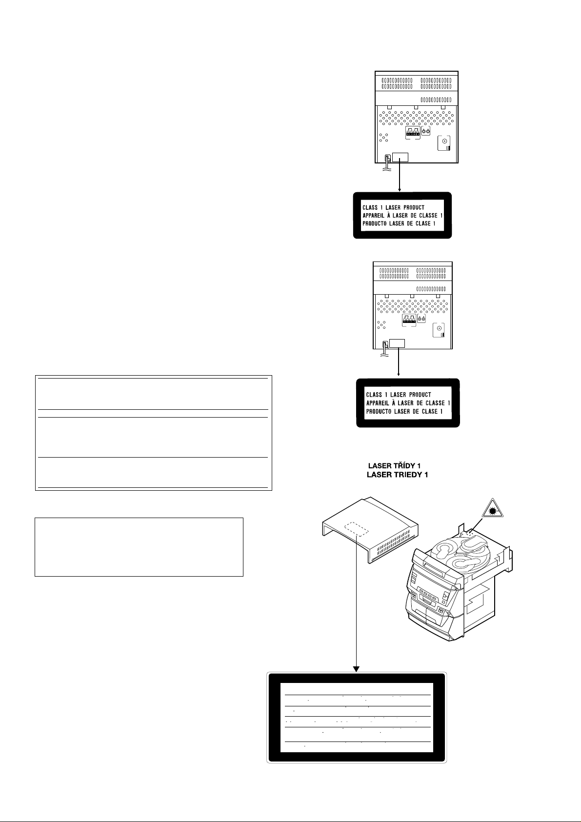
Precaution to be taken when replacing and servicing the
Laser Pickup.
The AEL (Accessible Emission Level) of Laser Power Output
for this model is specified to be lower than Class I Requirements.
However, the following precautions must be observed during
servicing to protect your eyes against exposure to the Laser
beam.
(1) When the cabinet has been removed, the power is turned
on without a compact disc, and the Pickup is on a position
outer than the lead-in position, the Laser will light for several
seconds to detect a disc. Do not look into the Pickup Lens.
(2) The Laser Power Output of the Pickup inside the unit and
replacement service parts have already been adjusted prior
to shipping.
(3) No adjustment to the Laser Power should be attempted
when replacing or servicing the Pickup.
(4) Under no circumstances look directly into the Pickup Lens
at any time.
(5) CAUTION - Use of controls or adjustments, or performance
of procedures other than those specified herein may result
in hazardous radiation exposure.
(Except for UK)
Laser Diode Properties
Material: GaAIAs
Wavelength: 780 nm
Emission Duration: continuous
Laser Output: max. 0.6 mW
VARNING-OSYNLIG LASERSTRÅNING NÄR DENNA DEL ÄR
ÖPPNAD. STIRRA EJ IN I STRÅLEN OCH BETRAKTA EJ STRÅLEN
MED OPTISKA INSTRUMENT.
VARO! AVATTAESSA OLET ALTTIINA NÄKYMÄTÖN
LASERSÄTEILYLLE.
ÄLÄ TUIJOTA SÄTEESEEN ÄLÄKÄ KATSO SITÄ OPTISEN
LAITTEEN LÄPI.
VARNING-OSYNLIG LASERSTRÅLNING NÄR DENNA DEL ÄR
ÖPPNAD. STIRRA EJ IN I STRÅLEN OCH BETRAKTA EJ STRÅLEN
GENOM OPTISKT INSTRUMENT.
(For UK)
LASER KLASSE 1
LUOKAN 1 LASERLAITE
KLASS 1 LASERAPPARAT
CAUTION-INVISIBLE LASER RADIATION WHEN OPEN. DO NOT STARE INTO
BEAM OR VIEW DIRECTLY WITH OPTICAL INSTRUMENTS.
VARNING-OSYNLIG LASERSTRALNING NAR DENNA DEL AR OPPNAD. STIRRA
EJ IN I STRALEN OCH BETRAKTA EJ STRALEN MED OPTISKA INSTRUMENT.
ADVERSEL-USYNLIG LASERSTRALING VED ABNING. SE IKKE IND I
STRALEN-HELLER IKKE MED OPTISKE INSTRUMENTER.
VARO! AVATTAESSA OLET ALTTIINA NAKYMATON LASERSATEILYLLE.
ALA TUIJOTA SATEESEEN ALAKA KATSO SITA OPTISEN LAITTEEN LAPI.
VARNING-OSYNLIG LASERSTRALNING NAR DENNA DEL AR OPPNAD.
STIRRA EJ IN I STRALEN OCH BETRAKTA EJ STRALEN GENOM OPTISKT
INSTRUMENT.
ADVERSEL-USYNLIG LASERSTRALING NAR DEKSEL APNES. STIRR IKKE
INN I STRALEN ELLER SE DIREKTE MED OPTISKE INSTRUMENTER.
CD-C430H,CP-C430H
– 3 –
FOR A COMPLETE DESCRIPTION OF THE OPERATION OF THIS UNIT, PLEASE REFER
TO THE OPERATION MANUAL.
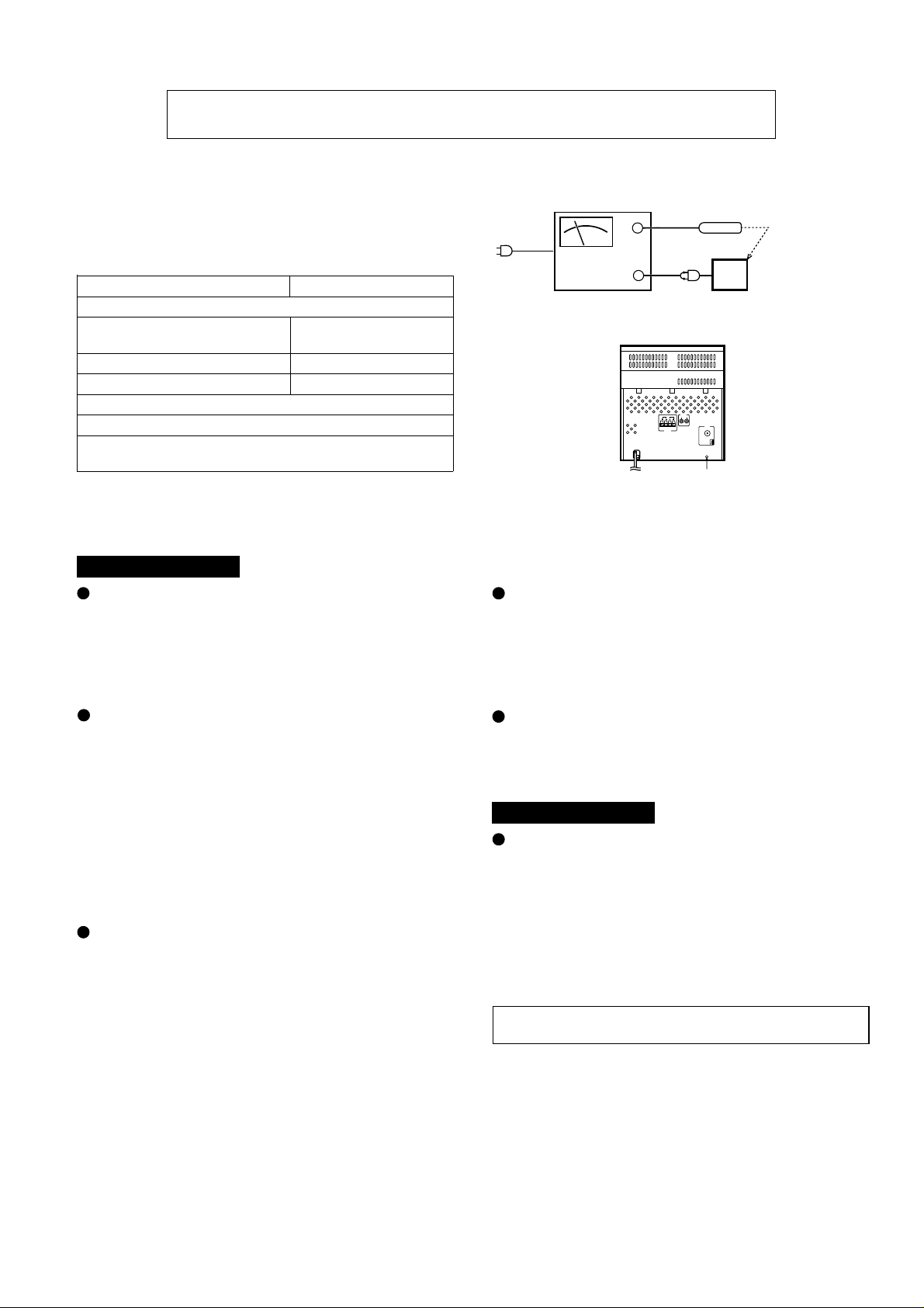
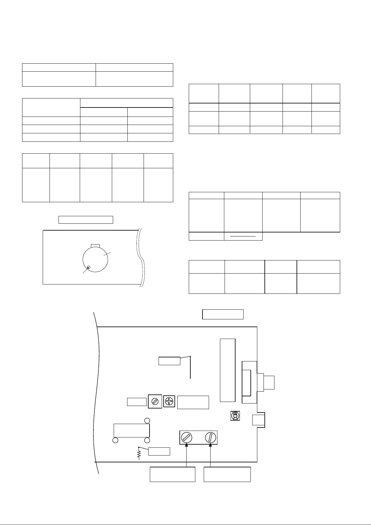
Before returning the unit to the customer after completion of a
repair or adjustment it is necessary for the following withstand
voltage test to be applied to ensure the unit is safe for the
customer to use.
Setting of Withstanding Voltage Tester and set.
Set name set value
Withstanding Voltage Tester
Test voltage 4,240 VPEAK
3,000 VRMS
Set time 6 secs
Set current(Cutoff current) 4 mA
Unit
Judgment
OK: The “GOOD” lamp lights.
NG: The “NG” lamp lights and the buzzor sounds.
SHORT-CIRCUIT
AC POWER
SUPPLY CORD
CONNECT THE PROBE
TO GND TERMINAL
OF PHONO TERMINAL
PROBE
AC
UNIT
WITHSTANDING
VOLTAGE TESTER
+
-
OUT
OF CHASSIS
SCREW
CHASSIS
SCREW
IMPORTANT SERVICE NOTES (FOR UK ONLY)
General
Power source: AC 230 V, 50 Hz
Power consumption: 90 W
Dimensions: Width; 270 mm (10-5/8")
Height; 300mm (11-13/16")
Depth; 359.5mm (14-3/16")
Weight: 5.3 kg (11.7 lbs.)
Amplifier section
Output power: PMPO; 320 W (total)
(Except for UK) MPO; 60 W (30 W + 30 W)
(10 % T.H.D.)
RMS; 40 W (20 W + 20 W)
(10 % T.H.D.)
Output power: MPO; 60 W (30 W + 30 W) (10 % T.H.D.)
(For UK) RMS; 40 W (40 W + 40 W) (10 % T.H.D.)
Output terminals: Speakers; 4 ohms
Headphones; 16-50 ohms
(recommended; 32 ohms)
Input terminals: Video/Auxiliary (audio signal);
245 mV/47 kohms
Tuner section
Frequency range: FM; 87.5 - 108 MHz
AM; 522 - 1,620 kHz
Compact disc player section
Type: 3-disc multi-play compact disc player
Signal readout: Non-contact, 3-beam semi-conductor
laser pickup
D/A Converter: 1-bit D/A converter
Frequency response: 20 - 20,000 Hz
Dynamic range: 90 dB (1 kHz)
Cassette deck section
Frequency response: 50 - 14,000 Hz (Normal tape)
Signal/noise ratio: 55 dB (TAPE 1, playback)
50 dB (TAPE 2, recording/playback)
Wow and flutter: 0.15 % (WRMS)
Speaker section
Type: 2-way 130 mm (5-1/8") woofer and 50
mm (2") tweeter type
Rated input power: 20 W
Maximum input power: 40 W
Impedance: 4 ohms
Dimensions: Width; 220 mm (8-11/16")
Height; 300 mm (11-13/16")
Depth; 225 mm (8-13/16")
Weight: 3.0 kg (6.6 lbs.)/each
SPECIFICATIONS
CD-C430H
CP-C430H
Specifications for this model are subject to change without prior
notice.
CD-C430H,CP-C430H
– 4 –
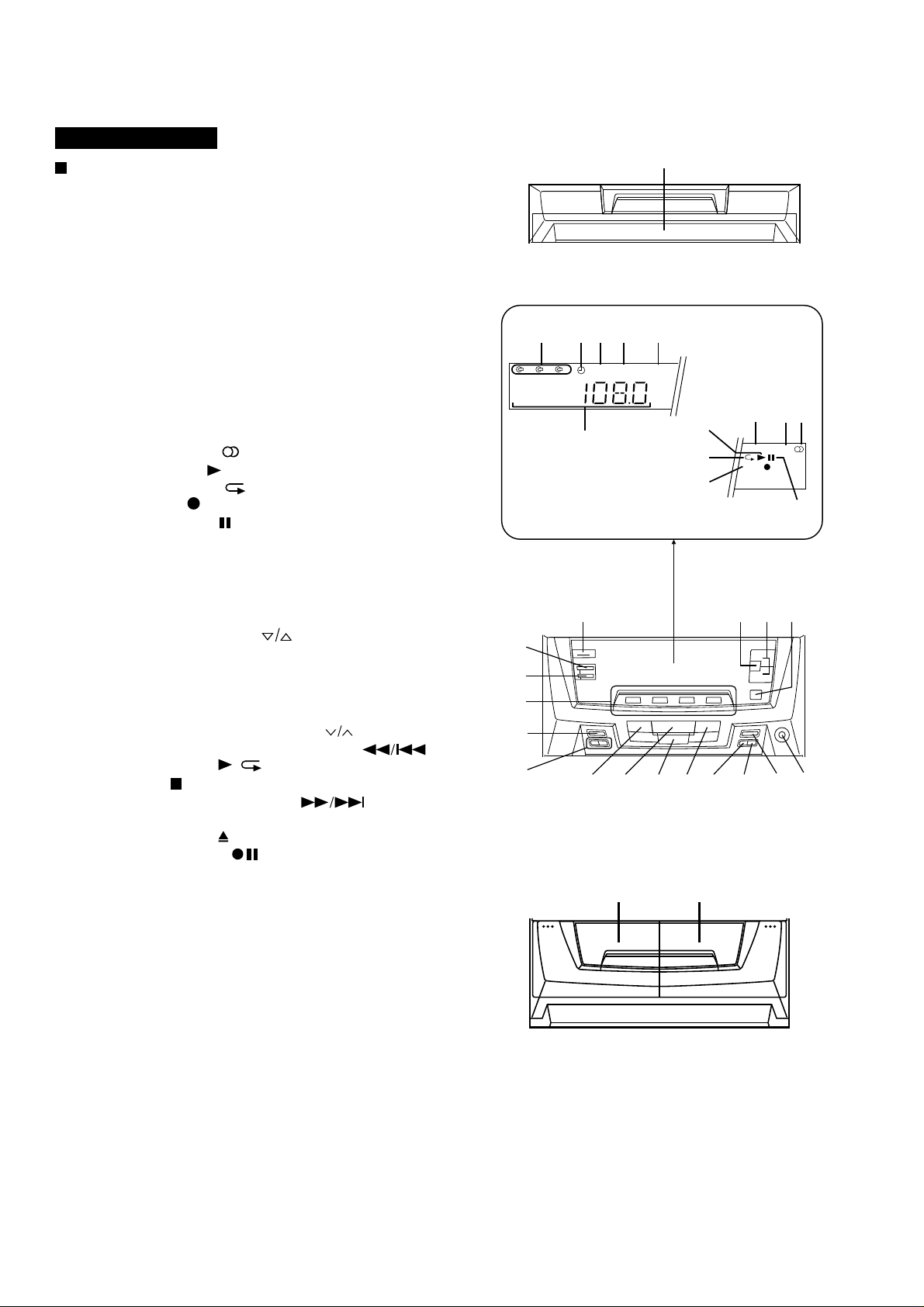
NAMES OF PARTS
Front Panel
1. Disc Tray
2. Disc Number Indicator
3. Timer Indicator
4. Record Indicator
5. Sleep Indicator
6. Extra Bass Indicator: X-BASS
7. Function/CD Track/CD Counter/Frequency/Preset
Channel/Volume/Timer/Sleep Time Indicator
8. Memory Indicator
9. FM Stereo Mode Indicator: ST
10. FM Stereo Indicator:
11. CD Play Indicator:
12. CD Repeat Indicator:
13. SRS Indicator: ( )
14. CD Pause Indicator:
15. On/Stand-by Switch
16. Extra Bass/Equalizer Mode Button
17. Volume Up/Down Buttons:
18. 3D Surround Mode Button
19. Clock Button
20. Timer/Sleep Button
21. Function Selector Buttons
22. Memory/Set Button
23. Tuning and Time Up/Down Buttons:
24. Track Down/Review/Preset Down Button:
25. Play/Repeat Button:
26. Stop Button:
27. Track Up/Cue/Preset Up Button:
28. Disc Skip Button
29. Open/Close Button:
30. Record Pause Button:
31. Headphone Socket
32. (TAPE 1) Cassette Compartment
33. (TAPE 2) Cassette Compartment
CD-C430H
/
1
MEMORY ST
kHz
SRS ( )
MHz
1 2 3
REC
SLEEP
X-BASS
2
3
4
5
6
7
8
9
10
11
12
13
14
16
18
19
20
21
22
23
24
25
26
2728 29 30 31
15
17
32
33
CD-C430H,CP-C430H
– 5 –
CD-C430H
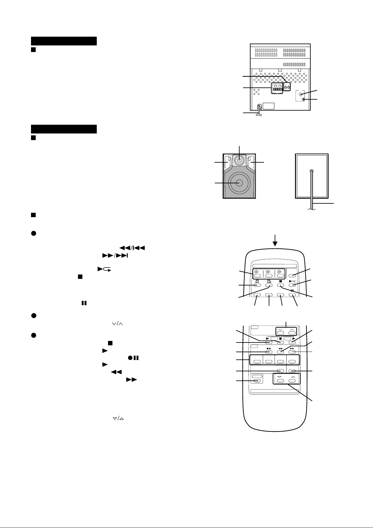
Rear Panel
1. Video/Auxiliary (Audio Signal) Input Sockets
2. Speaker Terminals
3. AC Power Lead
4. FM 75 Ohms Aerial Socket
5. AM Loop Aerial Input Socket
CP-C430H
Speaker Section
6. Tweeter
7. Bass Reflex Duct
8. Woofer
9. Speaker Wire
Remote Control
1. Remote Control Transmitter LED
CD Control section
2. Disc Number Select Buttons
3. Track Down/Review Button:
4. Track Up/Cue Button:
5. Disc Skip Button
6. Play/Repeat Button:
7. Stop Button:
8. Memory Button
9. Clear Button
10. Random Button
11. Pause Button:
Tuner control section
12. Preset Up/Down Buttons:
Tape control section
13. (TAPE 1/2) Stop Button:
14. (TAPE 1) Play Button:
15. (TAPE 2) Record Pause Button:
16. (TAPE 2) Play Button:
17. (TAPE 2) Rewind Button:
18. (TAPE 2) Fast Forward Button:
19. Function Selector Buttons
20. Extra Bass/Equalizer Mode Button
21. 3D Surround Mode Button
22. Power Button
23. Volume Up/Down Buttons:
1
2
3
4
5
6
77
8
9
1
2
3
4
5
6
7
11
12
10
98
14
13
15
19
23
20
18
17
16
22
21
CD-C430H,CP-C430H
– 6 –
OPERATION MANUAL
ON/
STAND-BY
CLOCK
MEMORY/
SET
TUNING/TIME
( )
AM 12:00AM 0:00
0:00
2
3
4
7
6
5
8
9
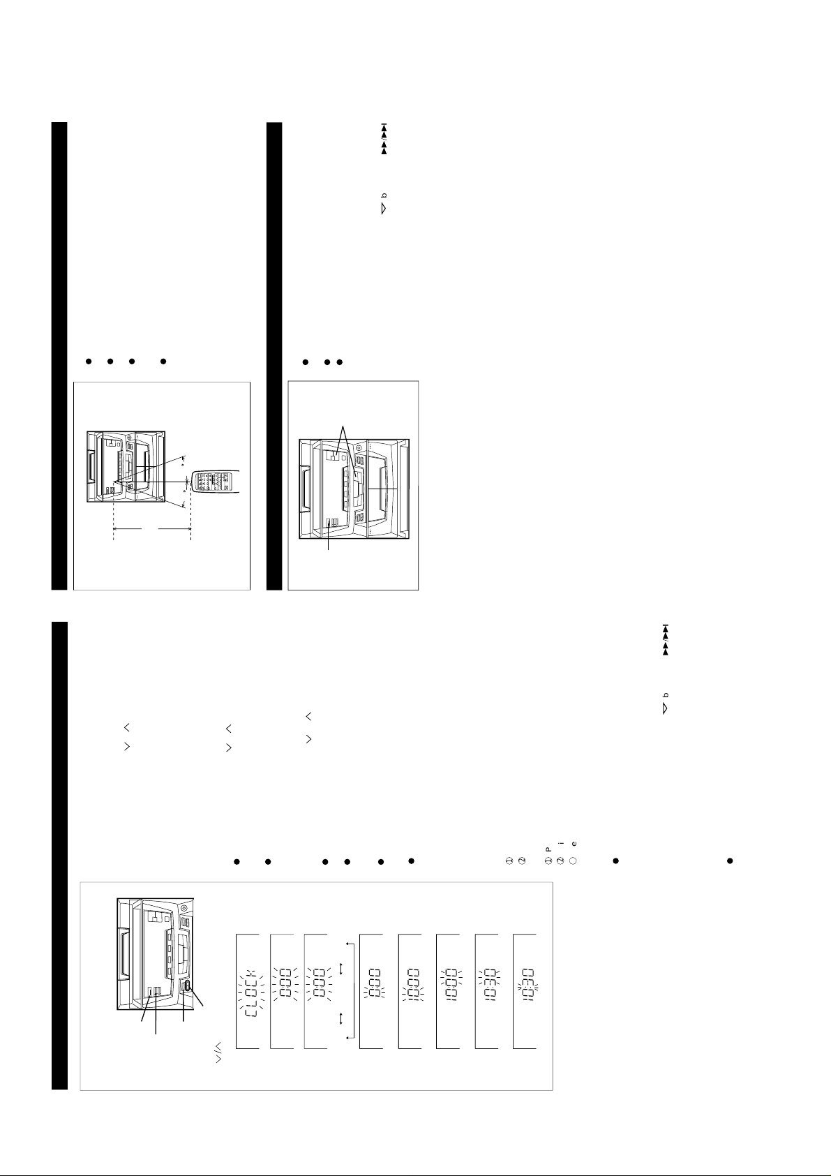
SETTING THE CLOCK
1
Press the ON/STAND-BY switch to enter the stand-by mode.
2
Press the CLOCK button.
3
Within 3 seconds, press the MEMORY/SET button.
4
Press the TUNING/TIME ( or ) button to select the time
display mode.
"0:00" → The 24-h our display will appear.
(0:00 - 23:59)
"AM 0:00" → The 12-hour display will appear.
(AM 0:00 - PM 11:59)
"AM 12:00" → The 12-hour display will appear.
(AM 12:00 - PM 11:59)
5
Press the MEMORY/SET button.
6
Press the TUNING/TIME ( or ) button to adjust the hour.
Press the TUNING/TIME button once to advance the time by
1 hour. Press for more than 0.5 seconds to advance continu-
ously.
When the 12-hour display is selected, "AM" will change auto-
matically to "PM".
7
Press the MEMORY/SET button.
8
Press the TUNING/TIME ( o r ) button to adjust the
minutes.
Press the button for at least 0.5 seconds to change the time
in 5-minute intervals.
The hour setting will not advance even if minutes advance
from "59" to "00".
9
Press the MEMORY/SET button.
The clock starts operating from "0" seconds. (Seconds are
not displayed.)
Note:
In the event of a power failure or when the AC power lead
is disconnected, the clock display will go out.
When the AC power supply is restored, the clock display will
flash on and off to indicate the time when the power failure
occurred or when the AC power lead was disconnected.
If this happens, follow the procedure below to change the
clock time.
To change the clock time:
When the ON/STAND-BY switch is set to STAND-BY.
1
Press the MEMORY/SET button.
2
Perform steps 6 - 9 above.
When the ON/STAND-BY switch is set to ON.
1
Press the CLOCK button.
2
Within 3 seconds, press the MEMORY/SET button.
3
Perform steps 6 - 9 above.
To see the time display: (When the power is ON)
Press the CLOCK button.
The time display will appear for about 3 seconds.
To switch the time display mode:
1
Press the ON/STAND-BY switch to enter the stand-by mode.
2
Press and ho ld down th e VOLUME butt on, the
button and the ON/STAND-BY switch all at the same time.
Hold them for at least 2 seconds.
(Refer to RESETTING THE MICROCOMPUTER on page 17.)
3
Perform steps 1 - 9 above.
Note:
The operation explained above will erase all data stored in
memory, such as clock and timer settings, tuner and CD pres-
ets.
In this example, the clock is set for the 24-hour
(0:00) system.
PREPARATION FOR USE
15
15
Notes concerning use:
Replace the batteries if control distance decreases or oper-
ation becomes erratic.
Periodically clean the transmitter LED on the remote control
and the sensor on the main unit with a soft cloth.
Exposing the sensor on the main unit to strong light may in-
terfere with operation. Change the lighting or the direction of
the unit.
Keep the remote control away from moisture, excessive heat,
shock, and vibrations.
0.2 m - 6 m
(8" - 20')
RESETTING THE MICROCOMPUTER
Reset the microcomputer under the following conditions:
To erase all of the stored memory contents (clock and timer
settings, tuner and CD presets).
If the display is not correct.
If the operation is not correct.
1
Press the ON/STAND-BY (POWER) switch to enter the stand-
by mode.
2
Press and hold down the VOLUME button, the
button and the ON/STAND-BY (POWER) switch all at the
same time. Hold them for at least 1 second.
1,2
2
CD-C430H,CP-C430H
– 7 –
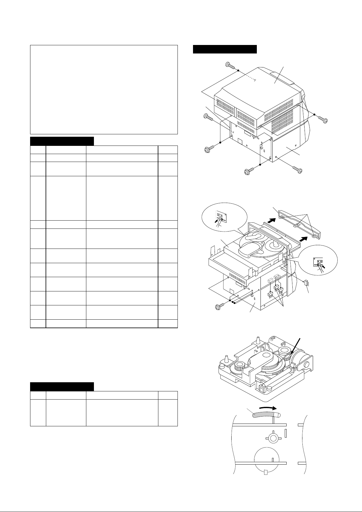
DISASSEMBLY
Caution on Disassembly
Follow the below-mentioned notes when disassembling
the unit and reassembling it, to keep it safe and ensure
excellent performance:
1. Take cassette tape and compact disc out of the unit.
2. Be sure to remove the power supply plug from the wall
outlet before starting to disassemble the unit.
3. Take off nylon bands or wire holders where they need be
removed when disassembling the unit. After servicing
the unit, be sure to rearrange the leads where they were
before disassembling.
4. Take sufficient care on static electricity of integrated
circuits and other circuits when servicing.
Figure 7-1
Figure 7-2
< A >
LOCK
LEVER
Figure 7-3
CP-C430H
CD-C430H
1 Top Cabinet 1. Screw ..................... (A1) x4 7-1
2 Side Panel 1. Screw ..................... (B1) x6 7-1
(Left/right)
3 CD Player Unit/ 1. Turn on the power supply, 7-2
CD Tray Cover open the disc tray, take out
the CD cover, and close.
(Note 1)
2. Hook....................... (C1) x3
3. Hook....................... (C2) x2
4. Socket .................... (C3) x4
4 Back Board 1. Screw ..................... (D1) x5 7-2
5 Main PWB/ 1. Screw ..................... (E1) x12 8-1
Display PWB/ 2. Socket .................... (E2) x4
Headphone PWB
6 Front Panel 1. Screw ..................... (F1) x2 8-1
2. Hook....................... (F2) x2
7 Tape Mechanism 1. Open the cassette holder. 8-2
2. Screw...................... (G1) x6
8 Turntable 1. Screw ..................... (H1) x1 8-3
2. Cover ..................... (H2) x1
9 Disc Tray 1. Screw ..................... (J1) x2 8-3
2. Guide ..................... (J2) x2
10 CD Changer 1. Screw ..................... (K1) x4 8-4
Mechanism
11 CD Mechanism 1. Screw ..................... (L1) x1 8-4
STEP
REMOVAL PROCEDURE
FIGURE
Note 1:
How to open the changer manually. (Fig. 7-3)
1. Insert the tip of fine screwdriver into the hole of CD player
base, and press down the worm wheel < A > .
2. Then, turn fully the lock lever in the arrow direction through
the hole on the loading chassis bottom in this state.
After that, push forward the CD player base.
CP-C430H
STEP REMOVAL
PROCEDURE
FIGURE
1 Speaker 1. Net Frame Ass'y ..... (A1) x1 7-5
2. Duct Front Panel ....(A2) x1
3. Screw...................... (A3) x4 7-6
4. Screw...................... (A4) x4
( B1 ) x1
ø3 x10mm
( B1 ) x2
ø3 x12mm
( B1 ) x2
ø3 x12mm
( B1 ) x1
ø3 x10mm
Top Cabinet
Side Panel
(Right)
Side Panel
(Left)
( A1 ) x2
ø3 x12mm
( A1 ) x2
ø3 x12mm
Back Board
CD Tray Cover
CD Player Unit
Hook
( C2 ) x1
Push
Hook
( C2 ) x1
Driver
Driver
Push
( D1 ) x6
ø3 x12mm
Hook
( C1) x3
( C3 ) x3
( C3 ) x1

CD-C430H,CP-C430H
– 8 –
Figure 8-3
Care when installing the CD changer mechanism.
Install the CD changer mechanism on the CD player base after
the shift lever has been set in the highest position.
( J1 ) x1
ø3 x10mm
( J1 ) x1
ø3 x10mm
( H1 ) x1
ø3 x10mm
Turntable
Disc Tray
( H2 ) x1
( J2 ) x1
( J2 ) x1
CD Player Unit
Figure 8-4
Figure 8-6
CP-C430H
Figure 8-2
( K1 ) x4
ø3 x12mm
( L1 ) x1
ø2.6 x10mm
CD Changer
Mechanism
CD Mechanism
Shift Lever
CD Player Base
Tape
Mechanism
Open
Cassette
Holder
Power Supply
PWB
Front Panel
( G1 ) x6
ø3 x10mm
( F1 ) x2
ø3 x10mm
Figure 8-1
( E1 ) x1
ø3 x10mm
( E1 ) x1
ø3 x12mm
( E1 ) x9
ø3 x10mm
( E2 ) x1
( E2 ) x2
( E1 ) x1
ø3 x10mm
Front Panel
Tape
Mechanism
( E2 ) x1
Display PWB
Main PWB
Speaker Box
(A2) x4
4 x32mm
(A2) x2
4 x10mm
Woofer
Figure 8-5
SHARP
Front Panel
(A1) x1
Speaker Box
Screw
driver
Driver should be pried
away from speaker Box.
Direction of handle
CD-C430H,CP-C430H
– 9 –
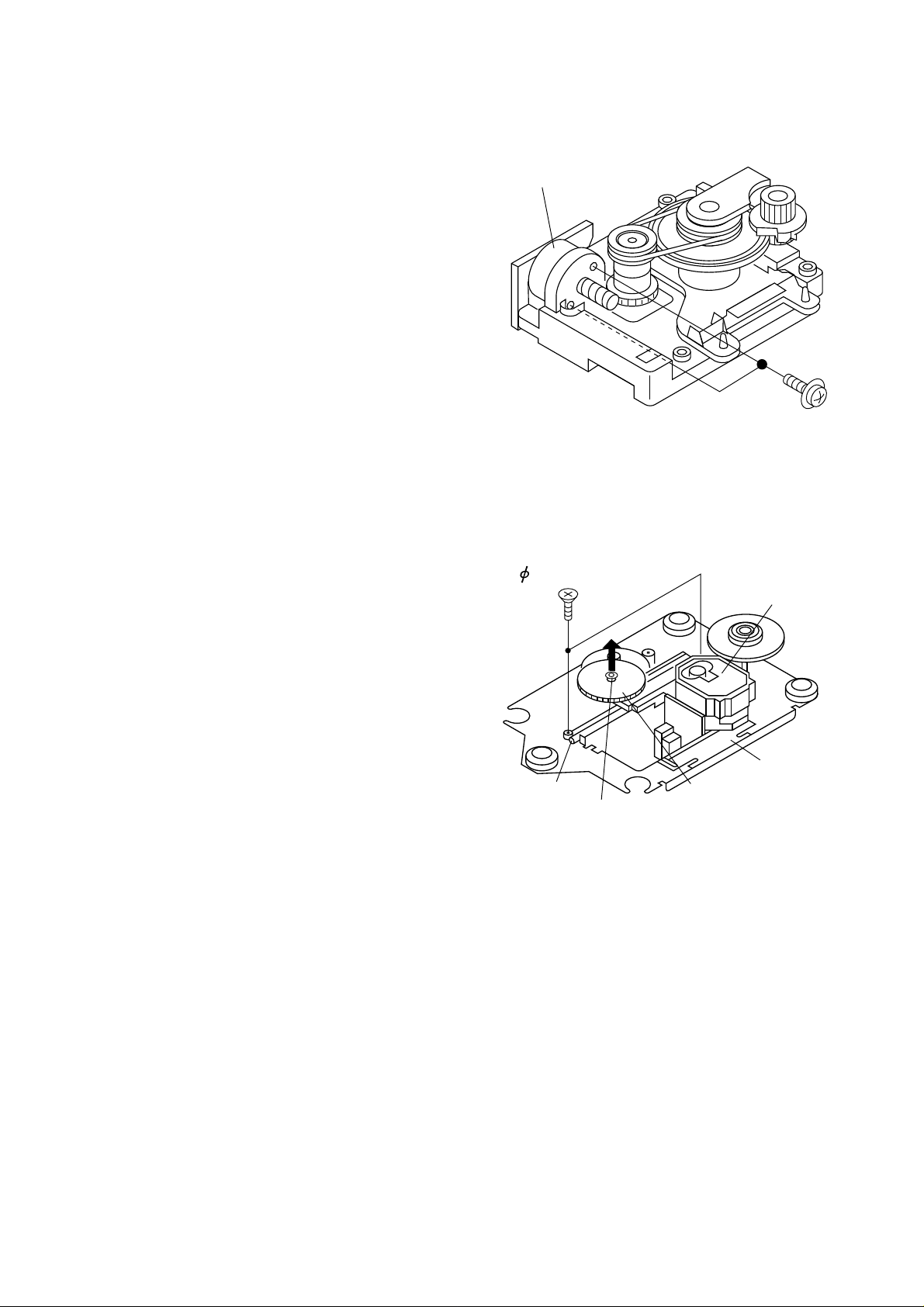
REMOVING AND REINSTALLING THE MAIN PARTS
CD MECHANISM SECTION
Perform steps 1, 2, 3, 10 and 11 of the disassembly method
to remove the CD mechanism.
How to remove the loading motor
(See Fig. 9-1)
1. Remove the screws (A1) x 2 pcs., to remove the loading
motor.
Figure 9-1
( A1 ) x2
ø2 x5mm
Loading Motor
Figure 9-2
How to remove the pickup (See Fig. 9-2)
1. Remove the screws (C1) x 2 pcs., to remove the shaft (C2).
2. Remove the stop washer (C3) x 1 pc., to remove the gear
(C4).
3. Remove the pickup.
( C1 ) x2
2.6 x6mm
( C2 ) x1
( C3 ) x1
( C4 ) x1
CD Mechanism
Pickup
CD-C430H,CP-C430H
– 10 –
MECHANISM SECTION
• Driving Force Check
Torque Meter
Specified Value
Play: TW-2412 Tape 1: Over 80 g
Tape 2: Over 80 g
• Torque Check
Torque Meter
Tape 2
Play: TW-2111 30 to 60 g. cm 30 to 60 g.cm
Fast forward: TW-2231 — 60 to 120 g.cm
Rewind: TW-2231 — 60 to 120 g.cm
Specified
Value
Adjusting
Point
Instrument
Connection
Test Tape
Normal MTT-111 Volume in 3,000 ± Speaker
speed motor. 30 Hz terminal
(Load
resistance:
8 ohms)
Specified Value
Tape 1
• Tape Speed
Figure 10-1 ADJUSTMENT POINTS
ADJUSTMENT
• AM IF/RF
Signal generator: 400 Hz, 30%, AM modulated
*1. Input: Antenna, Output: Speaker Terminal
*2. Input: Input is not connected, Output: TP301
TUNER SECTION
fL: Low-range frequency
fH: High-renge frequency
IF 990 kHz 990 kHz T351 *1
Band — 522 kHz (fL): T302 *2
Coverage 1.1 ± 0.1 V
Tracking 990 kHz 990 kHz T302 *1
Test Stage
Frequency Frequency
Display
Setting/
Adjusting
Parts
Instrument
Connection
• Setting the Test Mode
Keeping the TUNING (DOWN) button and MEMORY button
pressed, turn on POWER. Then, the frequency is initially set
in the memory as shown in Table. Call it with the PRESET
button to use it for adjustment and check of tuner circuit.
1 87.50 MHz 6 522 kHz
2 108.00 MHz 7 1,620 kHz
3 90.00 MHz 8 603 kHz
4 106.00 MHz 9 1,404 kHz
5 98.00 MHz 10 990 kHz
11 ~ 40
Preset No.
FM
Preset No.
AM
Adjusting
Parts
Instrument
Connection
Frequency
Display
Frequency
98.00 MHz 98.00 MHz VR351 *1 Input: So301
(25 dBµV) Output: Speaker
Terminal
• FM Mute Level
Signal generator: 1 kHz, 40 kHz dev. FM modulated.
*1. Adjust so that an output signal appears
TAPE MECHANISM
MM 1
Motor
Volume in motor
TUNER PWB
AM BAND
COVERAGE fL
ANTENNA
TERMINAL
T351
R331
L311
CNP301
T302
FE301
VR351
FM MUTE
LEVEL
AM IF
TP302
TP301
IC303
13
1
21
AM TRACKING
fL
SO301
CD-C430H,CP-C430H
– 11 –
TEST MODE
2
1
TO
TE
200 ms
1V/diV
IC 1 15
200 ms
1V/diV
IC 1 7
TRACKING/
ERROR
BARANCE
ADJUST
Figure 11-2
Figure 11-3
2
1
10ms
0.50 V
IC1 20 FE
10ms
0.50 V
IC1 7 TE
Enlarged
View
TRACKING
OFF-SET
ADJUST
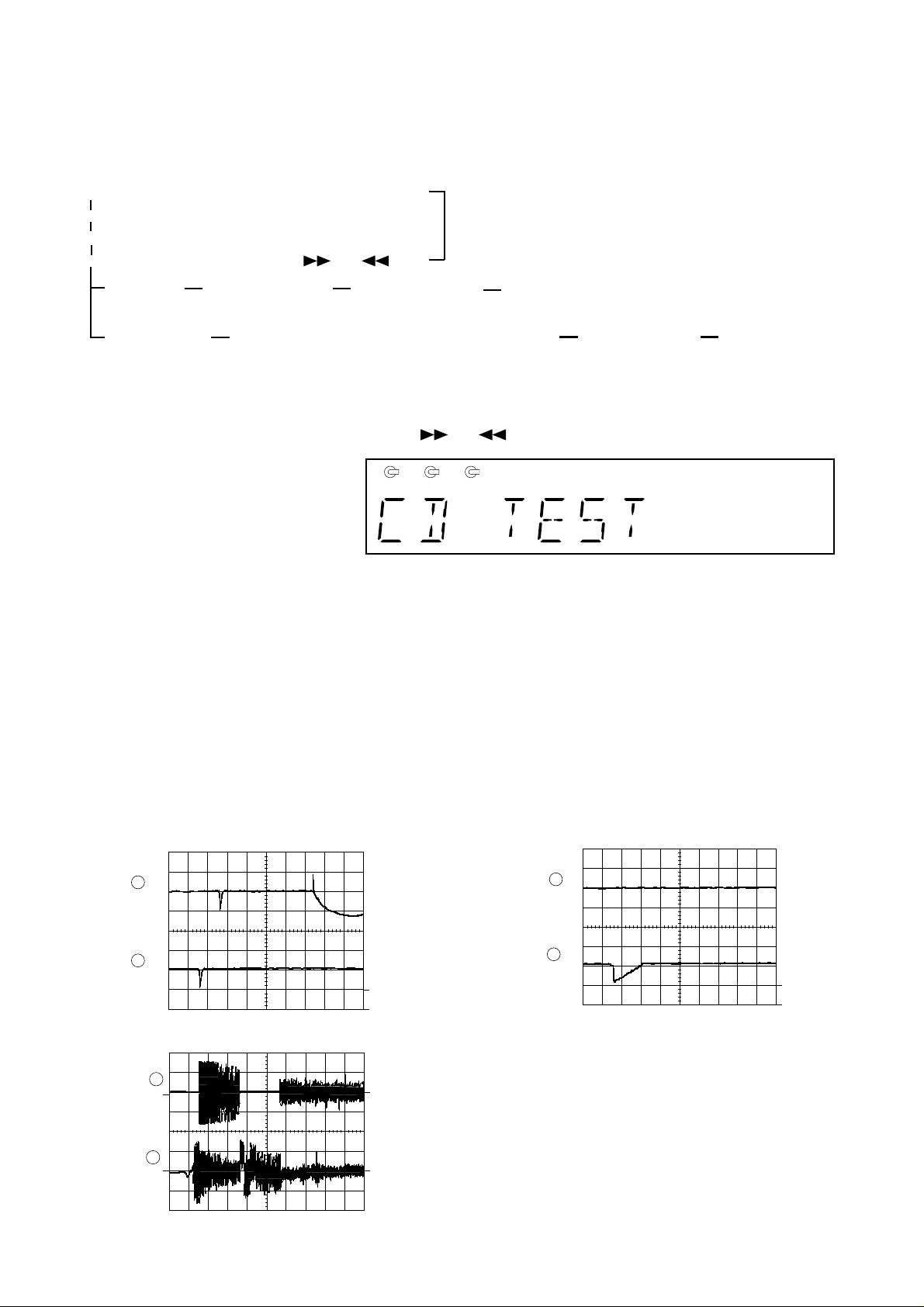
Since this CD system incorporates the following automatic adjustment function, when the pickup is replaced, it is not necessary
to readjust it.
Since this CD unit does not need adjustment, the combination of PWB and laser pickup unit is not restricted.
• Automatic adjustment item
1. Focus offset (Fig. 11-2)
2. Tracking offset (Fig. 11-3)
3. E/F balance (tracking error balance) (Fig. 11-4)
4. RF level AGC function (HF level: constant)
5. RF level automatic follow-up of the tracking gain
This automatic adjustment is performed each time a disc is changed. Therefore,
each disc is played back using the optimal settings.
CD SECTION
Figure 11-1
Note:
Only in STOP state it is possible to slide the pickup with the ( ) or ( ) key.
VOL. --- Last memory
BAL. --- CENTER
R.GEQ. --- FLAT
X-BAS --- OFF
Canceling method - POWER OFF
• Setting the test mode
Any one of test mode can be set by pressing several keys as follows.
<REC. PAUSE> + <DISC. SKIP> + <POWER> TEST: CD operation test
• TEST mode
Function — CD test mode
Setting of TEST mode
Indication of CD TST mode (Fig. 11-1)
OPEN/CLOSE operation is manual operation.
The pickup can be moved by using the (
) or ( ) key.
<MEMORY>
LASER ON
<PLAY> key input Press <STOP> key.
Stop
TOC. IL is performed, and the ordinary PLAY is performed.
If the following key is pressed during PLAY, it is possible
to specify directly any Track No.
<Disc Number 1> key: Track 4
<Disc Number 2> key: Track 9
<Disc Number 3> key: Track 15
<MEMORY>
Tracking on the spot.
SERVO OFF PLAY
<MEMORY>
Tracking on the spot.
SERVO ON PLAY
STOP
2
0.1s
0.50 V
IC1 20 FE
0.1s
0.50 V
IC1 7 TE
1
FOCUS
OFF-SET
ADJUST
TRACKING
OFF-SET
ADJUST
Figure 11-4
IL is not performed.
<STOP>
1 2 3
CD-C430H,CP-C430H
– 12 –
• The indicated voltage in each section is the one measured
by Digital Multimeter between such a section and the chas-
sis with no signal given.
1. In the tuner section,
( ) indicates AM
< > indicates FM stereo
2. In the main section, a tape is being played back.
3. In the deck section, a tape is being played back.
( ) indicates the record state.
4. In the power section, a tape is being played back.
5. In the CD section, the CD is stopped.
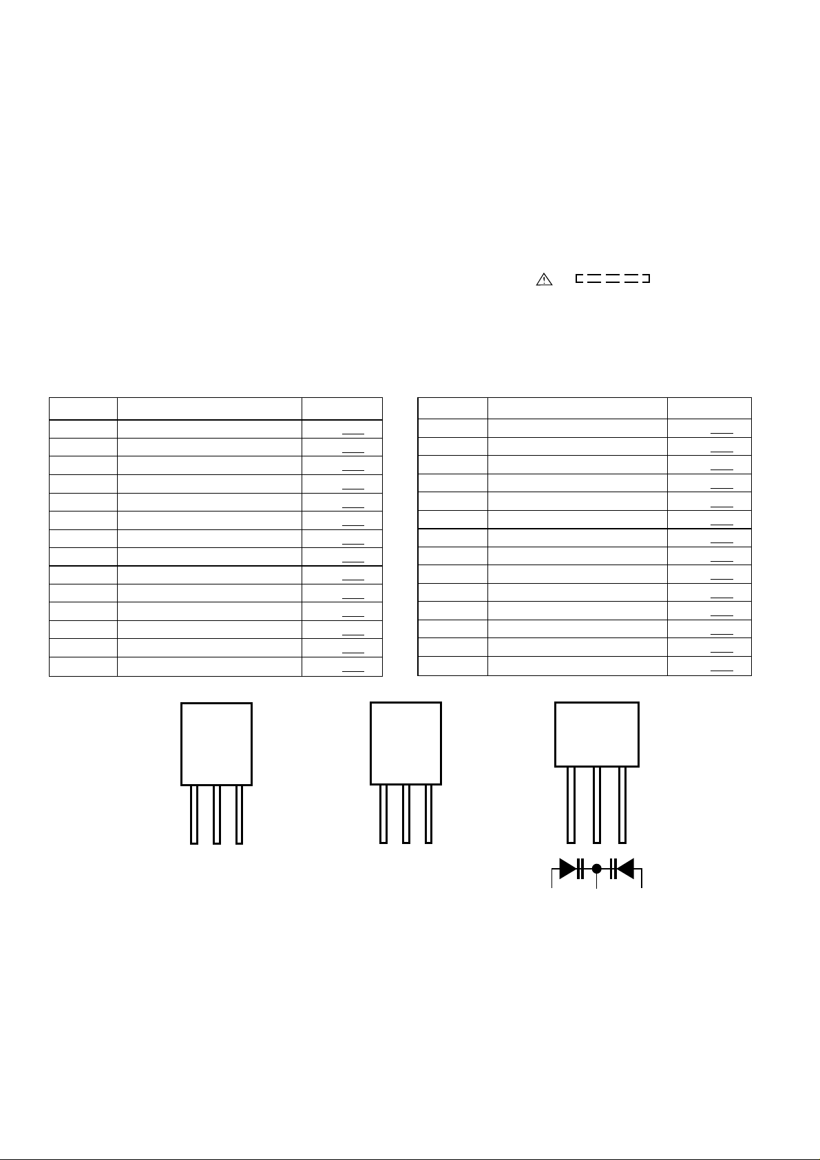
• Parts marked with “ ” ( ) are important for
maintaining the safety of the set. Be sure to replace these
parts with specified ones for maintaining the safety and
performance of the set.
NOTES ON SCHEMATIC DIAGRAM
• Resistor:
To differentiate the units of resistors, such symbol as K and
M are used: the symbol K means 1000 ohm and the symbol
M means 1000 kohm and the resistor without any symbol is
ohm-type resistor. Besides, the one with “Fusible” is a fuse
type.
• Capacitor:
To indicate the unit of capacitor, a symbol P is used: this
symbol P means micro-micro-farad and the unit of the
capacitor without such a symbol is microfarad. As to
electrolytic capacitor, the expression “capacitance/withstand
voltage” is used.
(CH), (TH), (RH), (UJ): Temperature compensation
(ML): Mylar type
(P.P.): Polypropylene type
• Schematic diagram and Wiring Side of P.W.Board for this
model are subject to change for improvement without prior
notice.
REF. NO DESCRIPTION POSITION
SW1 OPEN/CLOSE ON—OFF
SW2 MECHA UP ON—OFF
SW3 DISC NUMBER ON—OFF
SW4 PICKUP IN ON—OFF
SW701 RANDOM/DEMO ON—OFF
SW702 VOLUME DOWN ON—OFF
SW703 X-BASS ON—OFF
SW704 VOLUME UP ON—OFF
SW705 OPEN/CLOSE ON— OFF
SW706 DISC SKIP ON—OFF
SW709 REC./PAUSE ON—OFF
SW710 UP ON—OFF
SW711 STOP ON—OFF
SW712 PLAY ON—OFF
POSITION
SW713 DOWN ON—OFF
SW714 TUNING UP ON—OFF
SW715 TUNING DOWN ON—OFF
SW717 POWER ON—OFF
SW718 CLOCK ON—OFF
SW719 TIMER/SLEEP ON—OFF
SW721 MEMORY/SET ON—OFF
SW722 CD ON—OFF
SW723 TUNER ON—OFF
SW724 TAPE ON—OFF
SW725 AUX ON—OFF
SWM 3 FOOL PROOF ON—OFF
SWM 4 F.A.S. ON—OFF
SWM 5 CAM ON—OFF
REF. NO DESCRIPTION
Figure 12 TYPES OF TRANSISTOR
ECB
(S)(G)(D)
(1) (2) (3)
FRONT
VIEW
BCE
(D)(G)(S)
(3) (2) (1)
FRONT
VIEW
2SD2012 Y
KDV147BKRC104 M
KRC107 M
KTA1266 GR
KTA1273 Y
KTC3199 GR
KTC3203 Y
2SA1015 GR
2SB561 C
2SC2389 SS
2SC535 C
KRA102 M
KRA109 M
KRC102 M
CD-C430H,CP-C430H
– 13 –
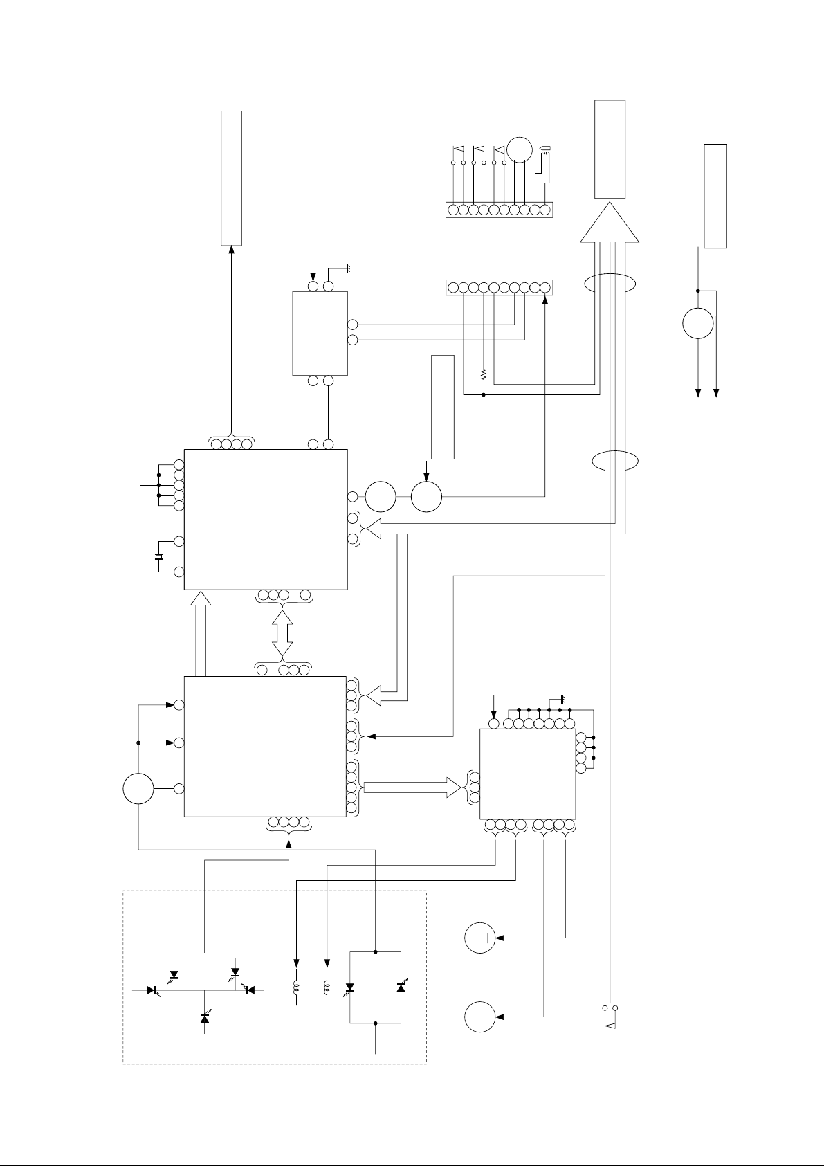
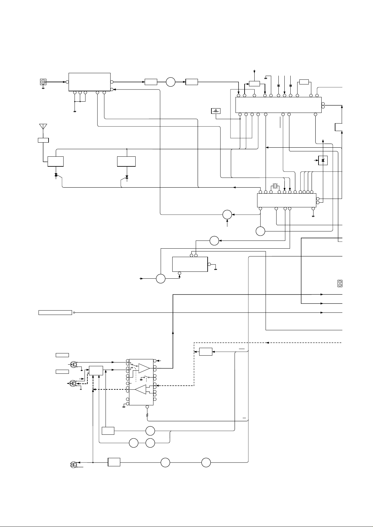
Figure 13 BLOCK DIAGRAM (1/3)
1
2
3
4
5
98
6
7
20
12
13
24
25
30
31
3222
34
35
36
10 11
27
26
28
29
PU-IN SW
XL1
XIN
LD0
FIN2
JP–
CV+
SLC
SL1
FIN1
E
F
TO
FD
SPO
SP
SLD
SL–
SL+
DRF
CL
DAT
CE
VCC1 VCC2
6
+5V
PICKUP IN
SW4
FOCUS COIL
TRACKING COIL
M1
SPINDLE
MOTOR
M
M
M2
SLED
MOTOR
PICKUP UNIT
9
IC2
LC78623D
SERVO/SIGNAL
CONTROL
+B5
IC5
M56748FP
DRIVER
IC1
LA9241M
SERVO AMP.
6
1
9
5
+B5
+12V(+B3)
( TO IC401 )
RES. CQCK. COIN
SQOUT. RWC. WRQ
~
~
~
CL, DAT, SELIAL CONTROL/CE
Q93
Q91
SL+. SL–. DRF
7
3
9
8
7
6
5
4
3
2
1
GND (D)
MECHA UP
GND (D)
DISK NO.
OPEN/CLOSE
GND (D)
M–
M+
GND (M)
9
8
7
6
5
4
3
2
1
CNP10
M
+5V
62
64
56 45 3623 43
37
38
39
40
24
25
10 10
265853
10
12
20
32
40
43
44
5352515431302923271615
4144
Q1
+5V
Q81 +5V (+B5)
VOLTAGE
REGULATOR
VOLTAGE
REGULATOR
VOLTAGE
REGULATOR
SWITCHING
FROM POWER AMP.
SECTION
TO MAIN SECTION
IC91
TA7291
MOTOR
CONTROL
XOUT
EFMO
EFMIN
CLV+
JP–
CONT2
CONT1
RCHO
RVSS
LVSS
LCHO
VVDD
VDD
LVDD
RVDD
XVDD
SW1
OPEN/CLOSE
SW2
MECHA UP
SW3
DISC NUMBER
M3
LOADING
SOLM1
TO DISPLAY
SECTION
CNS10
+B5
FROM POWER AMP.
SECTION
CD-C430H,CP-C430H
– 14 –
Figure 14 BLOCK DIAGRAM (2/3)
TAPE
TUNER
CD
1
3
4
5
17
18
13
6
7
16
14
12
19
10
23
24
8
9
1
26
15
27
2
4
20
21
R-CH
L-CH
PB HEAD
L NF
L (T1)
R (T1)
L (T2)
R (T2)
R NF
H/N
T1/T2
POP REDUCE
L REC
R REC
R NF
REC
L NF
P. B.
REC
L-CH
R-CH
REC/PB
HEAD
ERASE
HEAD
OCS
BIAS
REF
ALC
T1/T2
PLAYBACK&RECORD/
PLAYBACK AMP.
IC101
AN7345K
L
R
P. B
Q128
L104
BIAS
Q106
Q103
~
P.B
REC
AC BIAS
Q107
Q108
Q111
Q109 Q110
T1/T2
MUTING
Q121
Q122
REC
+B4
L
R
TAPE 1
TAPE 2
R
L
SWITCHING
SWITCHING
SWITCHING
SWITCHING
Q206
Q201
SRS 12V
+B4
VCC
MODE
Q124
Q126
SWITCHING BIAS
FROM CD SECTION
SO401
VIDEO/
AUX.
IC201
SRS5250S
SRS
CIRCUIT
1
3
4
5
1
7
7
8 9
6
20 12 22 15 16 11
21
17
13
10
1
5
42
7
3
8
6
8
9
17
14
15
12
1021222324
13
18
16
5
4
3
2
6
X352
4.5MHz
OSC
STEREO
ST
ST
AM IF
FM IF IN
VT
FM IN
AM IN
FM
+B4
AM
TRACKING
AM BAND
COVERAGE
FE301
FM FRONT END
CE
DI
CL
DO
T351
IC302
LC72131
PLL
FM
SWITCHING
FM IF
CF302
CF301
Q301
VCC
SO301
ANTENNA
TERMINAL
AM LOOP
ANTENNA
L311
BALUN
Q360
+B4
Q361
VR351
FM MUTE LEVEL
FM OSC
IF OUT
AM RF IN
AM OSC IN
AM OSC OUT
AFC
Q3
5
SD
FM/AM
MUTING
+B6
+B4
REGURATER
VOLTAGE
L-CH
R-CH
L354
+B6
MONO/ST
MIX
OUT
REG
FM
DET
Q3
5
X351
CF351
IC303
LA1832
FM IF DET./FM MPX./AM IF
T304
AM AMT.
CD-C430H,CP-C430H
– 15 –
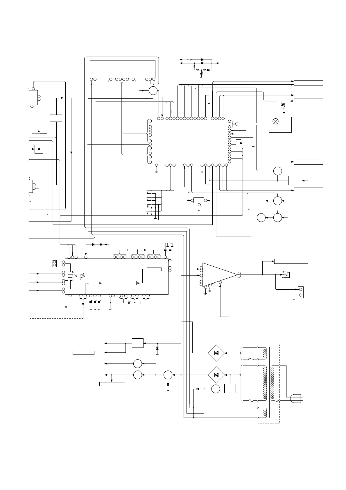
Figure 15 BLOCK DIAGRAM (3/3)
13
14
4
3
11
MUTE
L
R
R
L-OUT
R-OUT
9
2
5
12
L-IN
R-IN
NF
7
8
VCC
+12V (ANALOG)
+B4
+12V (MOTOR)
+B3
OUT
IC801
LA4550
POWER AMP.
+B4
PRESET GRAPHIC EQUALIZER
VDD
X-BASS
LVREF
RVREF
VSS
AVSS
GRAPHIC EQUALIZER
VOLUME
58
55
L
R
R
R
L
L
L
TAPE
TUNER
CD
Q942
VOLTAGE
REGULATOR
VOLTAGE
REGULATOR
VOLTAGE
REGULATOR
TO CD SECTION
UN-SWITCHED
+B6
+
–
SO801
SPEAKER
TERMINAL
JK801
HEADPHONES
VREF
OUT_L
TO CD SECTION
+5V
+5V
+B5
Q941
Q943
Q952
Q953
IC401
LC75394E
AUDIO PROCESSOR
23
16
33
17
32
19
30
21
28
14
13 35 56 50 26 27 12 37 11 38 10 3963
24 25 57
CL
DI
CE
25
27
29
30
33
34
35
36
37
38
39
40
42
414344454647485051525556
31
65
70
57
2423222120191817
77
79
80
72
71
161514131211
10
9
~
6
1
~
~
7
8
3
RX701
1
2
SYSTEM STOP
DO
DRF
DI
DE
CL
RESET
XL701
4.19MHz
AVDD
AVREF
+B7
+B8
KEY
SW701~706
SW709~715
SW717~725
+B3
PHM1
RESET
Q708
Q709
ZD701
MEMORY
BACK UP
+B7
+B8
+B7
+B8
3
2
1~
3314
2117 18 ~
30 31 32
Q701
+B7
+B7
VSS
+B6
UN-SWITCHED
FL701
DISPLAY
~
61
64
~
POWER
VOLTAGE
REGULATOR
Q971
D971
D973
~
D961 ~ D964
+B2
+B1
ZD972
VF2
–VP
VF1
Q707
Q706
IC701
IX0191AW
SYSTEM CONTROL
MICROCOMPUTER
+B3
TO CD SECTION
+B9
+B8
D965 ~ D968
9
43
6
40
49
64
8
44
5
41
7
45
4
42
CD PUIN
CD SL+
CD SL–
VDD
TAPE SOL
TAPE MOTOR
TAPE MECHASTOP
TAPE FP
T1 RUN PLSE
SOLM2
SOLENOID
+B9
SWM5
CAM
SWM4
F. A. S
SWM3
FOOL PROOF
L-CH INPUT
R-CH INPUT
T2 RRUN PLSE
CD UP DOWN/DISC NO
CD DSP RES
CD T/T OPEN/CLOSE
RESET
CD DSP SQOUT
CD DSP COIN
CD DSP RWC
CD DSP CQCK
CD DSP WRQ
T1/T2
TAPE REC
TAPE BIAS
SO401
VIDEO/
AUX.
ZD951
ZD941
TO DISPLAY PWB
Q705
MM1
TAPE
MOTOR
CONSTANT
VOLTAGE
+B3
M
TO CD SECTION
TO CD SECTION
TO POWER AMP.
SECTION
21
17
13
14
15
12
136
ST FM
DO
Q354
FM/AM
MUTING
+B6
L-CH
R-CH
MONO/ST
Q353
T.F
AC POWER
SUPPLY CORD
AC 230 V,50 Hz
F962
T2.5A L
250V
T961
POWER
TRANSFORMER
F963
T1.6A L
250V

CD-C430H,CP-C430H
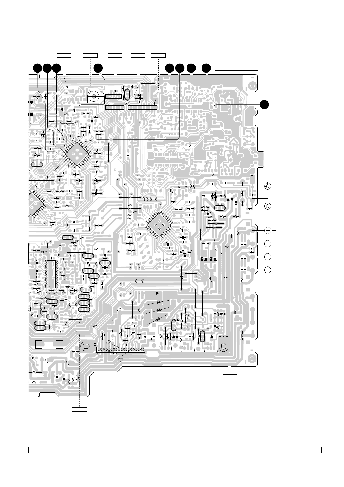
– 16 –
A
B
C
D
E
F
G
H
1
23456
Figure 16 WIRING SIDE OF P.W.BOARD (1/4)
• The numbers 1 to 12 are waveform numbers shown in page 30.
C96
TO TAPE MECHANISM
PWB
CNPM1
CNSM1
RD
1
2
3
4
5
6
7
8
9
10
11
12
WH
GY
WH
GY
WH
GY
WH
T
O
P19 7 - H
TO MOTOR PWB
CNS10
P18 2 - H
TO TAPE MECHANISM
CNS101
HEADPHONS PWB-A3DISPLAY PWB-A2
P18 2 - A
BR
COLOR TABLE
RD(R)
OR
YL
GR
BL
VL
GY
WH(W)
BK
PK
BROWN
RED
ORANGE
YELLOW
GREEN
BLUE
VIOLET
GRAY
WHITE
BLACK
PINK
F1
T500mA L 25
0
123
123
BCE
BCE
CNP101
XL701
BIM1
R773
R771
R759
C717
R99
R765
R769
R775
R98
R760
R799
R711
R603
C718
R726
R727
R700
R703
R705
R706
R709
R731
R743
R735
R702
R724
R708
R714
R748
R746
R707
R712
R704
R729
R747
R745
C704
C703
C701
R761
C705
R722
R772
R717
R719
R721
R713
R715
R716
R718
R720
R723
R725
R762
R766
C708
R779
R734
R741
R781
R780
R776
R786
R785
R798
R795
R767
R782
R737
R728
R730
R754
R732
R733
R757
R756
R751
R750
R738
R774
R70
R755
R739
R752
R740
R744
R797
R742
R96
R788
R31
C95
R39
R54
R30
R25
R24
R23
R22
R21
C16
C2
0
R26
R2
7
R81
R38
R56
R57
C51
C22
R47
R46
C46
C54
C56
C55
C57
R77
R78
R154
R134
R150
R141
C58
R152
R137
R135
C129
R71
R72
R79
R153
C139
R139
R145
C131
R131
C119
R125
C127
R123
R121
R102
C117
C123
C113
C111
R107
C10
7
R101
C102
R108
C10
8
C101
R110
C1
C1
R60
R58
R
3
C
3
R
3
R2
C1
R1
R701
Q701
C710
C711
FL701
RX701
Q706
D702
R758
C706
Q705
D709
D708
CNP10
C91
R97
IC91
D91
Q91
R95
Q93
C715
R789
R770
R792
R793
R749
C702
R794
L701
D701
Q707
D703
C707
Q708
Q709
ZD701
C709
D704
D706
D705
R763
R777
R836
R835
C855
R764
R133
R172
R768
R736
D5
D7
R49
R82
R61
C43
R778
R88
R87
R783
C44
C11
C17
C18
C19
C81
C52
Q81
R86
L1
L700
C53
C59
R3
5
XL1
R45
C135
Q121
C
C148
C141
C133
IC101
C128
C115
R119
Q107
R109
Q10
8
Q111
Q110
C453
C809
C454
R811
C812
C843
C844
C811
R809
C813
8
1
SW717
POWER
TIMER/SLEEP
SW719
SW718
CLOCK
1
2
3
10
987654321
9
8
7
6
5
4
3
2
1
B
C
E
B
C
E
SW714
TUN-UP
SW715
TUN-DOWN
SW721
MEMORY/SET
123
BCE
STOP
SW711
PLAY
SW712
SW724
TAPE
SW713
DOWN
TUN
SW723
CD
SW722
IC701
5
10
15
20
24
25
30
35
4041
45
50
55
60
64
65
70
75
80
IC701
5
10
15
20
24
25
30
35
4041
45
50
55
60
64
65
70
75
80 1
SW725
VIDEO/AUX
SW710
UP
SW705
OP/CL
SW706
D-SKIP
SW709
REC/PAUSE
SW703
X-BASS
SW701
RANDOM/DEMO
123
BCE
BCE
123
SW704
VOL-UP
SW702
VOL-DOWN
HEADPHONES
JK801
BCE
3
2
1
BCE
1
5
10
12
15
20
1
5
10
15
1617
20
25
30
32
33
35
40
45
48
49
50
55
60 64
IC2
ECB
IC5
1
51015
18
36
35 30 25 20
19
C121
1
2
3
4
5
6
7
8
9
10
11
12
13
14
15
16
17
18
19
20
21
22
23
24
25
26
27
28
29
30
31
32
33
1
2
65411
7
L107
R117
R753
R753R753
R753
C96
C147
CD-C430H,CP-C430H
– 17 –
Figure 17 WIRING SIDE OF P.W.BOARD (2/4)
7
8 9 10 11 12
L-CH
SO401
VIDEO/AUX
R-CH
L-CH
SO801
SPEAKERS
R-CH
P18 6 - H
TO CD MOTOR
PWB
CNS3A
P18 5 - C
TO PICKUP
UNIT
CNS2A
P18 5 - C
TO PICKUP
UNIT
CNS1A
P19 9 - C
TO TUNER
PWB
CNP201
P19 9 - C
TO TUNER
PWB
CNP303
MAIN PWB-A1
P19 10 - B
TO POWER PWB
CNS901
NISM
P18 3 - H
TO TAPE MECHANISM
CNS102
CNP901
F1
T500mA L 250V
ECB
123
123
BCE
BCE
CNP101
R825
CNP102
R31
R39
R24
R23
R22
R21
C16
C20
R26
R27
R81
R38
R56
R57
C22
R47
R46
R134
R150
R141
R152
R137
C139
C131
C127
R102
C113
C111
R107
C107
R101
C102
R108
C108
C101
R110
R114
R115
C106
R106
C105
R104
R118
C112
R103
C114
R105
R113
C120
R122
R124
C118
R166
R126
C124
C132
R132
R168
R138
R164
R140
C130
R162
C140
R146
R167
R142
R136
R74
C70
R76
C92
R73
C69
R75
R60
R58
R36
R37
C33
C31
R32
C32
R34
R33
C30
R41
C38
R1
C1
R20
C15
R2
C14
R19
C10
R3
R16
R8
R17
R15
R4
R11
C12
R14
R9
R5
R12
C4
R7
R13
R6
R42
C25
R43
C456
C446
R413
R411
C413
C433
R414
R412
C437
C414
R479
C438
C445
C434
R480
R945
R808
R807
R804
C945
R948
C941
R803
C804
C803
R806
R805
R949
C957
C871
C872
C408
R407
C407
R406
R408
R405
C455
CNP3
C44
CNP2
C94
R10
C21
C7
R29
C13
R28
C11
C17
C18
C19
C81
C52
Q81
C45
C53
C50
R35
C34
C42
C41
R18
C67
R45
C68
Q122
C146
R158
C136
C135
C145
C148
C142
C141
C133
C134
IC101
C128
C122
C115
C116
R119
R120
Q107
R112
R111
R109
Q108
Q111
Q110
53
C809
C810
454
811
C812
C811
C820
C814
R812
R810
809
C813
LG902
C831
C802
C801
C830
C829
C808
C806
C823
C824
C828
Q106
R815
C825
Q104
Q103
Q105
C150
C109
R478
R477
Q109
L104
Q126
C151
C153
Q128
R174
Q124
C152
C218
R160
R476
C422
C452
C420
C418
C406
C405
C412
C402
R420
R419
R418
C401
R416
R415
R403
D2
C37
C35
R475
C39
C40
C2
C404
C3
C403
C5
C8
C6
C9
CNP401 CNP402
D403
CNP1
D404
Q1
C24
R422
C451
C217
R421
C411
C975
R417
R402
R401
C417
R974
C421
C419
C976
ZD972
C423
C425
R976
C427
C435
C439
C961
C440
C443
C444
C436
D402
C424
D962
D964
D961
C426
C442
C428
C441
D401
C944
D967
C956
D968
C955
D966
R946
ZD941
D965
R947
C943
C942
Q943
C827
C805
R943
C948
D942
D941
C947
R951
Q953
D951
R944
Q942
Q941
Q952
LG901
R952
C952
ZD951
C953
R953
C954
D963
C962
R977
R978
R975
R844
R843
R845
C971
C972
Q971
R973
D971
D973
D972
C974
C973
R972
ZD971
C410
C409
C845
C849
C847
C851
C848
C852
C846
C850
7
6
5
4
3
2
1
ECB
ECB
ECB
BCE
3
2
1
BCE
BCE
123
BCE
1
5
10
12 13
15
20
24
BCE
1
5
10
15
1617
20
45
48
49
50
55
60 64
IC2
ECB
1
5
10
15
20
25
30
32
33
35
40
45
48
50
55
60 64
IC1
1
1
65432
6587432
1
65432
10 15
18
25 20
19
1
10987654321
5432
B
C
E
123456
ECB
IC401
1
5
10
15
1617
20
25
30
32
33
35
40
45
48
49
50
55
60
64
E
C
B
E
BCEBCEBCE
C
B
123456789
10 11 12 13 14
IC801
123456789
10 11 12 13 14
C121
2
3
981126 10
7
L107
L108
L105
L831
L832
R117
C147
 Loading...