


CDMPS-700
CD-MPS700
SERVICE MANUAL
No. XXXXXXXXXXXXX
SHARP CORPORATION
CONTENTS
Parts marked with " " are important for maintaining the safety of the set. Be sure to replace these parts with specified ones for
maintaining the safety and performance of the set.
This document has been published to be used
for after sales service only.
The contents are subject to change without notice.
CHAPTER 1. GENERAL DESCRIPTION
[1] Specifications ................................................. 1-1
[2] Names of parts............................................... 1-2
CHAPTER 2. ADJUSTMENTS
[1] Mechanism section ........................................ 2-1
[2] Tuner section ................................................. 2-1
[3] TEST MODE .................................................. 2-2
[4] CD section...................................................... 2-4
[5] CD Changer mechanism section ................... 2-5
CHAPTER 3. MECHANISM BLOCKS
[1] Caution on diassembly................................... 3-1
[2] Removing and reinstalling the main parts ........ 3-4
CHAPTER 4. DIAGRAMS
[1] Block diagrams............................................... 4-1
CHAPTER 5. CIRCUIT DESCRIPTION
[1] Notes on schematic diagram.......................... 5-1
[2] Types of transistor and LED........................... 5-1
[3] Waveforms of CD circuit ................................ 5-2
[4] Voltage ........................................................... 5-3
CHAPTER 6. CIRCUIT SCHEMATICS AND PARTS
LAYOUT
[1] Schematic diagram ........................................6-1
[2] Wiring side of PWB...................................... 6-11
CHAPTER 7. FLOWCHART
[1] Troubleshooting .............................................7-1
CHAPTER 8. OTHERS
[1] Function table of IC .......................................8-1
[2] FL Display....................................................8-10
Parts Guide
MINI COMPONENT SYSTEM
CD-MPS700
MODEL
CD-MPS700 Mini Component System consisting of CD-MPS700
(main unit) and CP-MPS700 (speaker system).
MINI COMPONENT SYSTEM
CD-MPS700
1 – 1
AudioCD-MPS700Service ManualCD-MPS700MarketE
CHAPTER 1. GENERAL DESCRIPTION
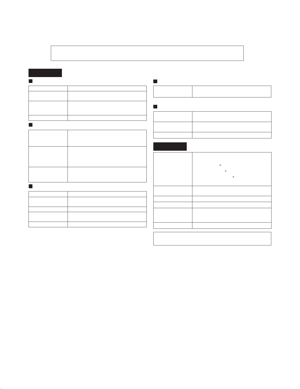
[1] Specifications
General
Amplifier
CD player
Tuner
Cassette deck
Power source AC 120 V, 60 Hz
Power
consumption
135 W
Dimensions Width: 10-1/4" (260 mm)
Height: 13" (330 mm)
Depth: 12-7/8" (326 mm)
Weight 18.5 lbs. (8.4 kg)
Output power MPO: 600 W (300 W + 300 W) (10 % T.H.D.)
RMS: 300 W (150 W + 150 W) (10 % T.H.D.)
RMS: 180 W (90 W + 90 W) (0.9 % T.H.D.)
Output terminals Speakers: 6 ohms
Headphones: 16 - 50 ohms
(recommended: 32 ohms)
Video output: 1Vp-p
Input terminals Game/ Auxiliary (audio signal):
500 mV/ 47 k ohms
Game/Video: 1 Vp-p/75 ohms
Type 5-disc multi-play compact disc player
Signal readout Non-contact, 3-beam semiconductor laser
pickup
D/A converter 1-bit D/A converter
Frequency
response
20 - 20,000 Hz
Dynamic range 90 dB (1 kHz)
Frequency range FM: 87.5 - 108.0 MHz
AM: 530 - 1,720 kHz
Frequency
response
50 - 14,000 Hz (normal tape)
Signal/noise ratio 55 dB (TAPE 1, playback)
50 dB (TAPE 2, recording/playback)
Wow and flutter 0.3 % (WRMS)
Type 3-way type speaker system with passive
radiator
Super tweeter 2
2" (5 cm) tweeter 1
6-1/2" (16 cm) woofer 1
4" (10 cm) passive radiator
Maximum input
power
300 W
Rated input power 150 W
Impedance 6 ohms
Dimensions Width: 10-7/8" (277 mm)
Height: 13" (330 mm)
Depth: 11" (279 mm)
Weight 8.6 lbs. (3.9 kg)/each
CD-MPS700
CP-MPS700
Specifications for this model are subject to change without
prior notice.
FOR A COMPLETE DESCRIPTION OF THE OPERATION OF THIS UNIT, PLEASE REFER
TO THE OPERATION MANUAL.
CD-MPS700
1 – 2
[2] Names of parts
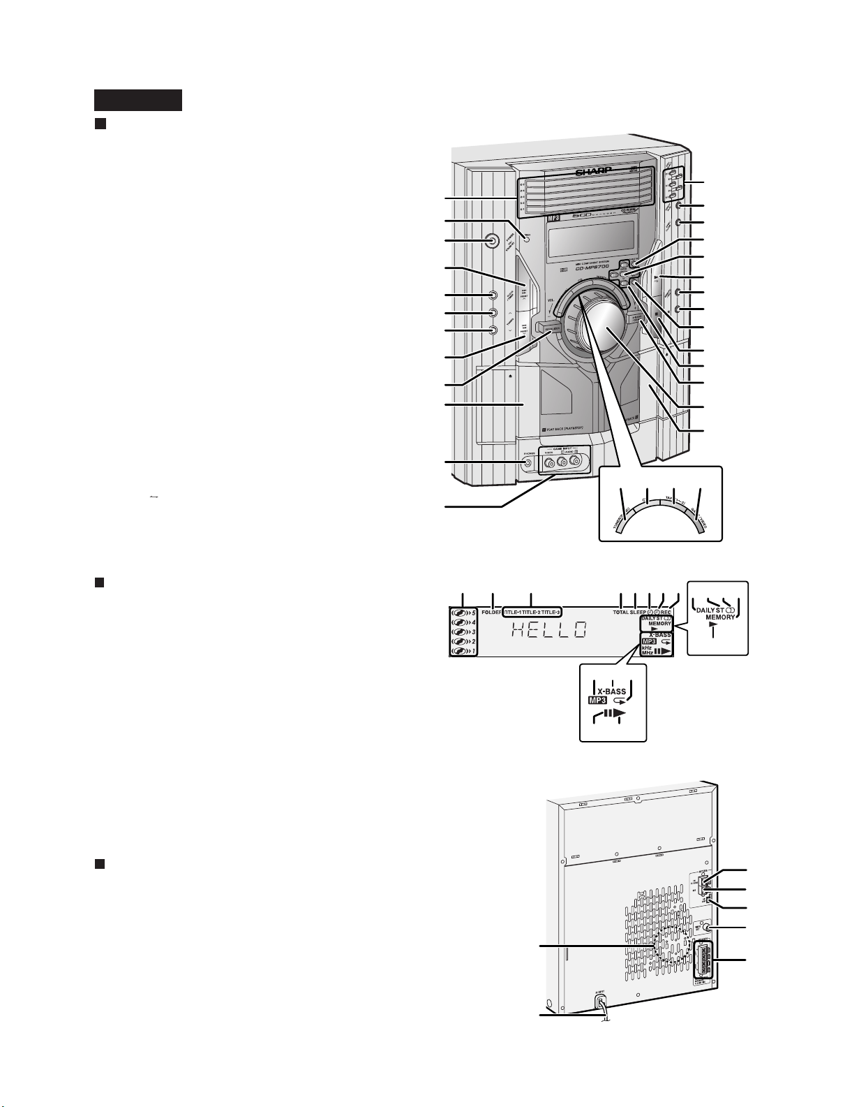
Front panel
1. Disc Trays
2. Timer Indicator
3. Power On/Stand-by Button
4. Disc Track Up or Fast Forward, Tape 2 Fast Forward,
Tuner Preset Up, Time Up Button
5. Clock/Timer Button
6. Tuning Up Button
7. Tuning Down Button
8. Disc Track Down or Fast Reverse, Tape 2 Rewind,
Tuner Preset Down, Time Down Button
9. Equalizer Mode Select Button
10. Tape 1 Cassette Compartment
11. Headphone Jack
12. Game/Video Input Jacks
13. Disc Number Select Buttons
14. Disc Direct Play Button
15. Disc Tray Open/Close Button
16. Character Button
17. Enter Button
18. Disc Play or Repeat, Tape Play Button
19. Memory/Set Button
20. Tape 2 Record Pause Button
21. MP3 Disc Navigation Mode Select Button
22. Disc or Tape Stop Button
23. Cursor Buttons
24. Extra Bass/Demo Mode Button
25. Volume Control
26. Tape 2 Cassette Compartment
27. Tuner (Band) Button
28. CD Button
29. Tape (1 2) Button
30. Game/Video Button
1
13
15
25
17
19
23
24
3
2
5
6
7
16
22
21
26
14
20
11
8
12
4
9
10
28 29 3027
18
CD-MPS700
Display
1. Disc Number Indicators
2. MP3 Folder Indicator
3. MP3 Title Indicators
4. MP3 Total Indicator
5. Sleep Indicator
6. Timer Play Indicator
7. Timer Recording Indicator
8. Tape 2 Record Indicator
9. Daily Timer Indicator
10. FM Stereo Mode Indicator
11. FM Stereo Receiving Indicator
12. Memory Indicator
13. Tape Play Indicator
14. MP3 Disc Indicator
15. Extra Bass Indicator
16. Disc Repeat Play Indicator
17. Disc Pause Indicator
18. Disc Play Indicator
4 532167 8
9
13
1110 12
14 15 16
17
18
Rear panel
1. Cooling Fan
2. AC Power Cord
3. FM 75 Ohms Antenna Terminal
4. FM Antenna Ground Terminal
5. AM Loop Antenna Jack
6. Video Output Jack
7. Speaker Terminals
1
5
3
6
4
7
2
CD-MPS700
1 – 3
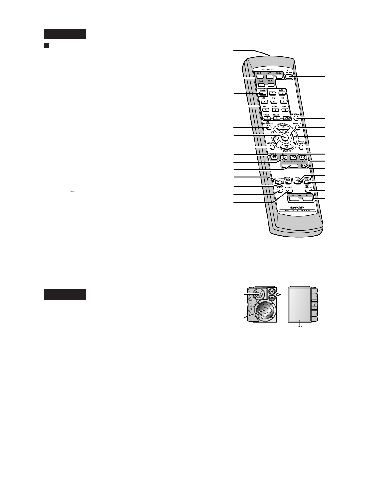
Remote control
1. Remote Control Transmitter
2. Disc Number Select Buttons
3. Clock/Timer Button
4. Character Input/Disc Direct Search Buttons
5. MP3 Disc Navigation Mode Select Button
6. Enter Button
7. Memory/Set Button
8. Tape 2 Record Pause Button
9. Disc Track Down or Fast Reverse, Tape 2 Rewind,
Tuner Preset Down, Time Down Button
10. Disc or Tape Stop Button
11. CD Button
12. Tuner (Band) Button
13. Equalizer Mode Select Button
14. Extra Bass Button
15. Power On/Stand-by Button
16. Disc Random Button
17. Character Button
18. Cursor Buttons
19. Disc Clear/Dimmer Button
20. Disc Pause Button
21. Disc Track Up or Fast Forward, Tape 2 Fast Forward,
Tuner Preset Up, Time Up Button
22. Disc Play or Repeat, Tape Play Button
23. Tape (1 2) Button
24. Game/Video Button
25. MP3 Disc Display Button
26. Volume Up and Down Buttons
1
2
3
4
5
7
9
15
16
17
18
19
24
25
26
12
13
10
21
22
23
20
14
6
8
11
CD-MPS700
CP-MPS700
1. Tweeter
2. Passive Radiator
3. Woofer
4. Super Tweeters
5. Speaker Wire
1
2
3
5
4
CD-MPS700
2 – 1
AudioCD-MPS700Service ManualCD-MPS700MarketE
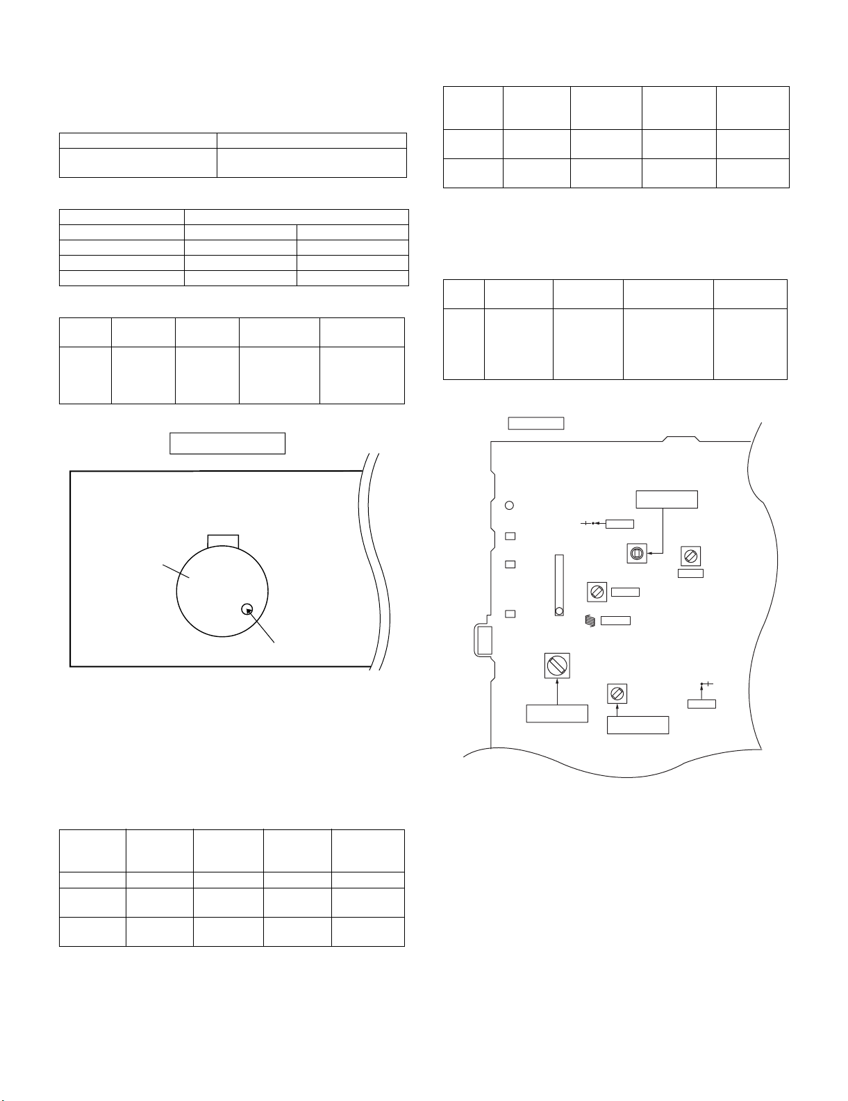
CHAPTER 2. ADJUSTMENTS
[1] Mechanism section
• Driving Force Check
• Torque Check
• Tape Speed
Figure 1
[2] Tuner section
fL: Low-range frequency
fH: High-range frequency
• AM IF/RF
Signal generator: 400 Hz, 30%, AM modulated
•FM RF
Signal generator: 1 kHz, 40 kHz dev., FM modulated
•FM IF
Signal generator: 10.7 MHz, FM modulated
Figure 2 Adjustment Points
Torque Meter Specified Value
Play: TW-2111 Tape 1: Over 80 g
Tape 2: Over 80 g
Torque Meter Specified Value
Tape 1 Tape 2
Play: TW-2111 30 to 80 g.cm 30 to 80 g.cm
Fast forward: TW-2231 — 70 to 180 g.cm
— 70 to 180 g.cm
Test Tape Adjust-
ing Point
Specified
Value
Instrument
Connection
Normal
speed
MTT-111 Variable
Resistor in
motor.
3,000 ± 30 Hz
Speaker
Speaker Ter-
minal (Load
resistance: 6
ohms)
Test Stage Frequency Frequency
Display
Setting/
Adjusting
Parts
Instrument
Connection
AM IF 450 kHz 1,720 kHz T351 *1
AM Band
Coverage
— 530 kHz (fL): T306
1.1 ± 0.1 V
*2
AM
Tracking
990 kHz 990 kHz (fL): T303 *1
*1. Input: Antenna Output: TP302
*2. Input: Antenna Output: TP301
TAPE MECHANISM
Tape
Motor
Variable Resistor in motor
Test
Stage
Frequency Frequency
Display
Setting/
Adjusting
Point
Instrument
Connection
FM Band
Coverage
— 87.50 MHz T301 (fL):
1.3 V ± 0.1 V
*1
FM RF 98.00 MHz
(10-30 dB)
98.00 MHz L312 *2
*1. Input: Antenna Output: TP301
*2. Input: Antenna Output: Speaker terminal
Test
Stage
Frequency Frequency
Display
Setting/Adjust-
ing Point
Instrument
Connection
IF 10.7 MHz 98 MHz T302 (Turn the
core of trans-
former T302
fully counter
clockwise)
*1
AM IF
FM RF
TP301
TP302
FM IF
T301
T302
R356
R381
T303
T306
IC301
L312
T351
CNP301
AM/FM LOOP ANTENNA
FM BAND
COVERAGE fL
AM BAND
COVERAGE fL
AM TRACKING
fL
MAIN PWB
1
CD-MPS700
2 – 2
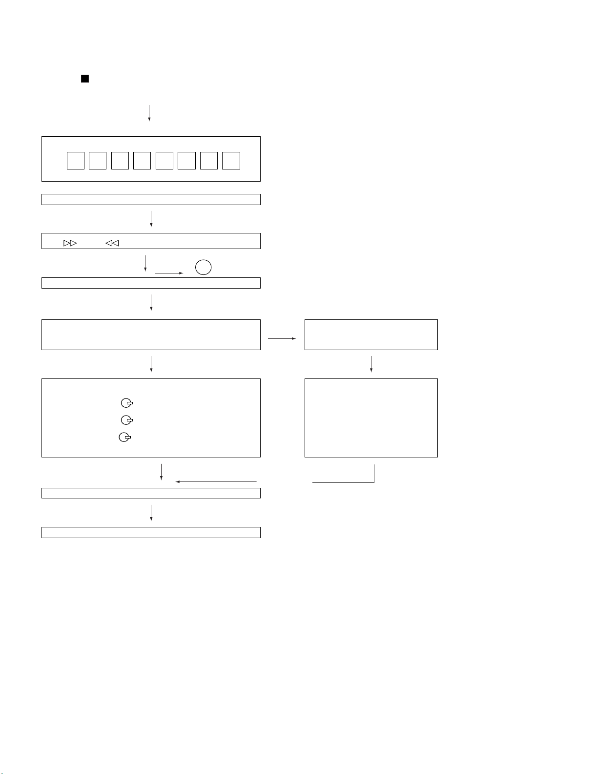
[3] TEST MODE
• Setting the test mode
During stand-by mode, press ON/STAND-BY button while pressing
down the button and X-BASS/DEMO button. then, press the CD
button to enter the test mode.
IL isn’t done
OPEN/CLOSE operation is using manual. IL isn’t done
<< >>,<< >>buttons make pick's slide possible.
IL isn’t done
to page 2-3
<<PLAY>> key input.
C D T E S T
A
Do TOC IL. Do normal play.
When these following key is input into PLAY key, track num-
ber can be appoint directly.
<<MEMORY>>
key input.
<< 1>> key: Track 4
<< 2>> key: Track 9
<< 3>> key: Track 15
Adjustment result automatically will
display as below for each 2 sec:
a) "FOF_XXXX"
b) "TOF_XXXX"
c) "TBAL_XX"
d) "TGAN_XX"
f) "FGAN_XX"
g) "RFLS_XX"
––––––––
<<STOP>> key input.
STOP
explanation:
a) Focus off set = "FOF_XXXX"
b)Tracking off set = "TOF_XXXX"
c)Tracking balance = "TBAL_XX"
d)Tracking Gain = "TGAN_XX"
f) Focus Gain = "FGAN_XX"
g) RF level shift = "RFLS_XX"
VOL — Last memory
P.GEQ — FLAT
X-BASS — OFF
To cancel : Power OFF
CD-MPS700
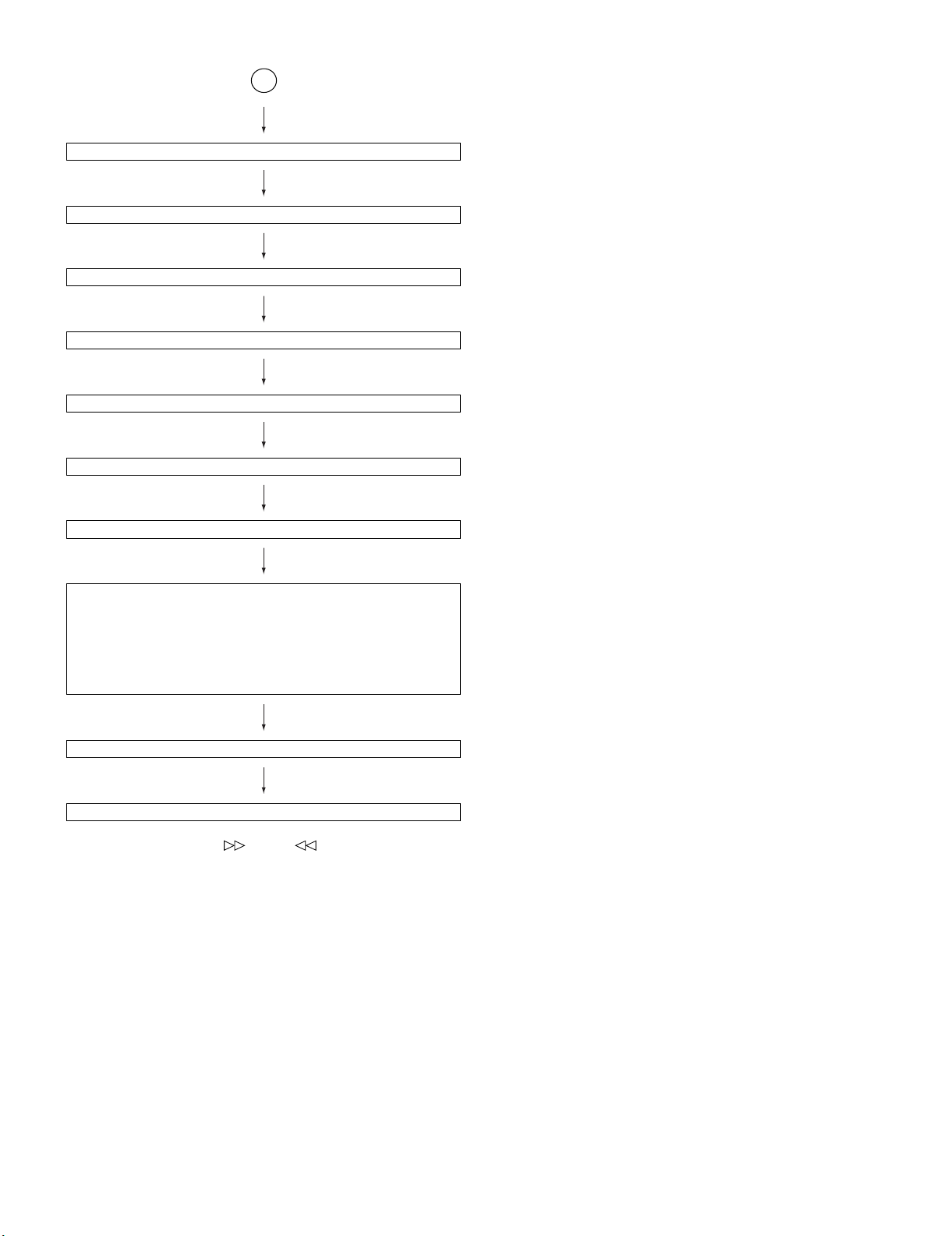
2 – 3
Sliding the PICKUP with<< >>, << >> button must only be
in STOP mode.
<<MEMORY>> key input.
Laser ON.
<<MEMORY>> key input.
Tracking OFF play at that specific point.
<<MEMORY>> key input.
Tracking ON play from that specific point.
<<MEMORY>> key input.
Adjustment result automatically will display as below for each 2 sec :
a) "FOF_XXXX"
b) "TOF_XXXX"
c) "TBAL_XX"
d) "TGAN_XX"
f) "FGAN_XX"
g) "RFLS_XX"
<<STOP>> key input.
STOP
explanation:
a) Focus off set = "FOF_XXXX"
b)Tracking off set = "TOF_XXXX"
c)Tracking balance = "TBAL_XX"
d)Tracking Gain = "TGAN_XX"
f) Focus Gain = "FGAN_XX"
g) RF level shift = "RFLS_XX"
VOL — Last memory
P.GEQ — FLAT
X-BASS — OFF
To cancel : Power OFF
A
CD-MPS700
2 – 4
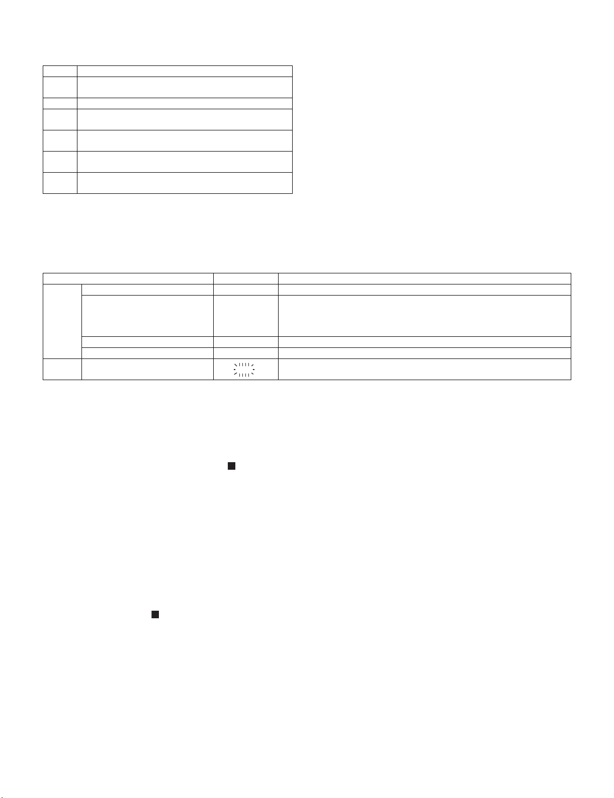
[4] CD section
CD Error code description
* 'CHECKING'
If Error is detected, 'CHECKING' will be displayed instead of 'ER-
CD**'. 'ER-CD**' display will only be displayed when error had been
detected for the 5th times.
Standard Specification of Stereo System Error Message Display Contents
(*) CHECKING:
If CD changer mechanism error is detected, 'CHECKING' will be dis-
play instead of 'ER-CD**'. 'ER-CD**' display will only be display when
error had been detected for the 5 th times.
Speaker abnormal detection and +B PROTECTION display
In case speaker abnormal detection or +B PROTECTION had
occurred, it can be check by pressing 'POWER', ' ' and 'X-BASS'
button. MicroComputer version number will displayed as "XM******".
Press ‘GAME/VIDEO’ button during version number display and then
press ‘POWER’, ‘MEMORY/SET’ and ‘GAME/VIDEO’ button. Display
will show "S** B**". S is referring to speaker abnormal detection and B
is referring to +B PROTECTION. ** is in hex valve.
+B PROTECTION is condition when irregular process occur on power
supply line.
BEFORE TRANSPORTING THE UNIT
The following process need to be taken after set tapering/parts
replacement.
1. Press the ON/STAND-BY button to enter stand-by mode.
2. While pressing down the button and the X-BASS/DEMO but-
ton, press the ON/STAND-BY button. The Micro Computer version
number will be displayed as "XM******".
3. Press OPEN/CLOSE button until "WAIT"→ "FINISHED" appears.
4. Unplug the AC cord and the unit is ready for transporting.
Error Explanation
01 When Pickup set inner position, inner switch cannot detect
'ON' level for 10 secs.
10* CAM error. Can't detect CAM switch when CAM is moving.
11* When it detect cam operation error during initialize pro-
cess.
20* TRAY error. Can't detect TRAY switch when TRAY is mov-
ing.
21* When it detect TRAY operation error during initialize pro-
cess.
31 When it change to CD function, DSP cannot read initial
data.
Error Contents Display Notes
CD Pickup Mechanism Error. 'ER-CD01' PU-IN SW Detection NG.
CD Changer Mechanism Error. 'ER-CD**' (*) 10: CAM SW Detection NG during normal operation
11: CAM SW Detection NG during initialize process
20:TRAY SW Detection NG during normal operation
21:TRAY SW Detection NG during initialize process
CD DSP Communication Error. 'ER-CD31' DSP COMMUNICATION ERROR.
Focus Not Match/IL Time Over. 'NO DISC'
TUNER PLL Unlock. PLL Unlock.
F
M 87.5 MH
z
CD-MPS700
2 – 5
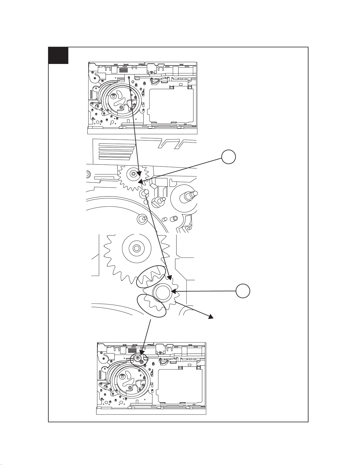
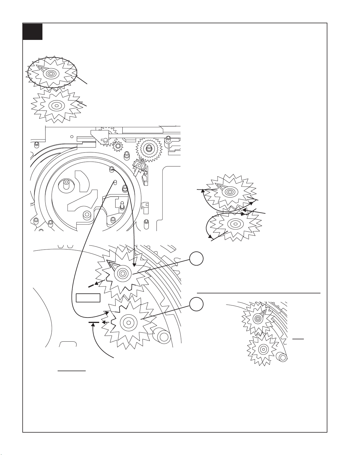
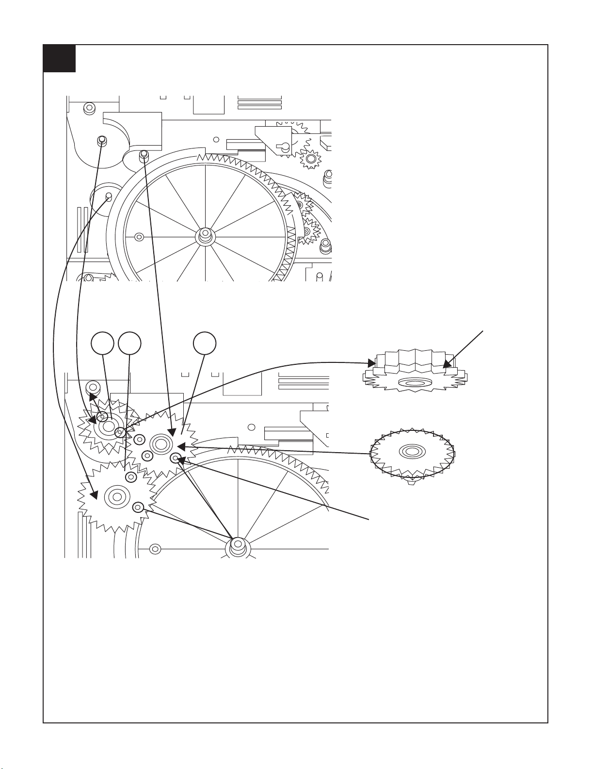
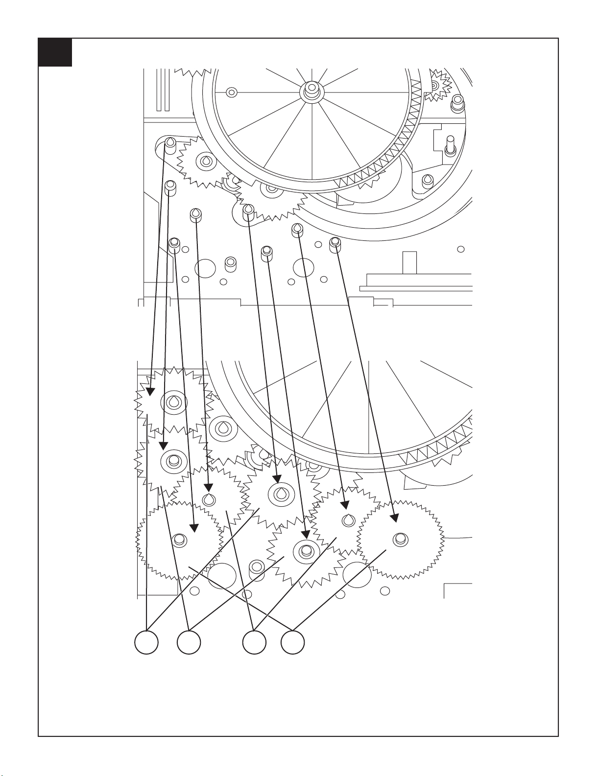
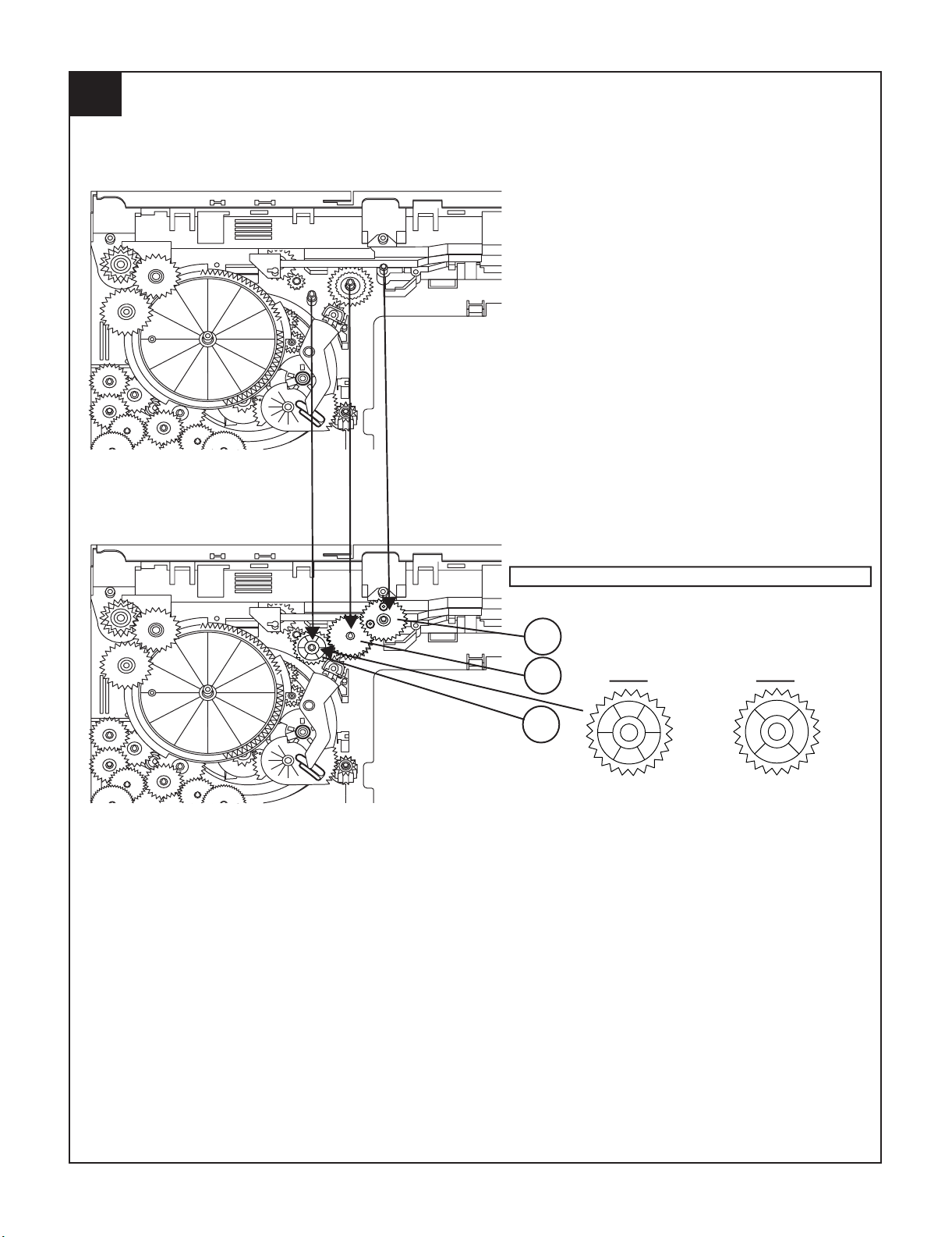
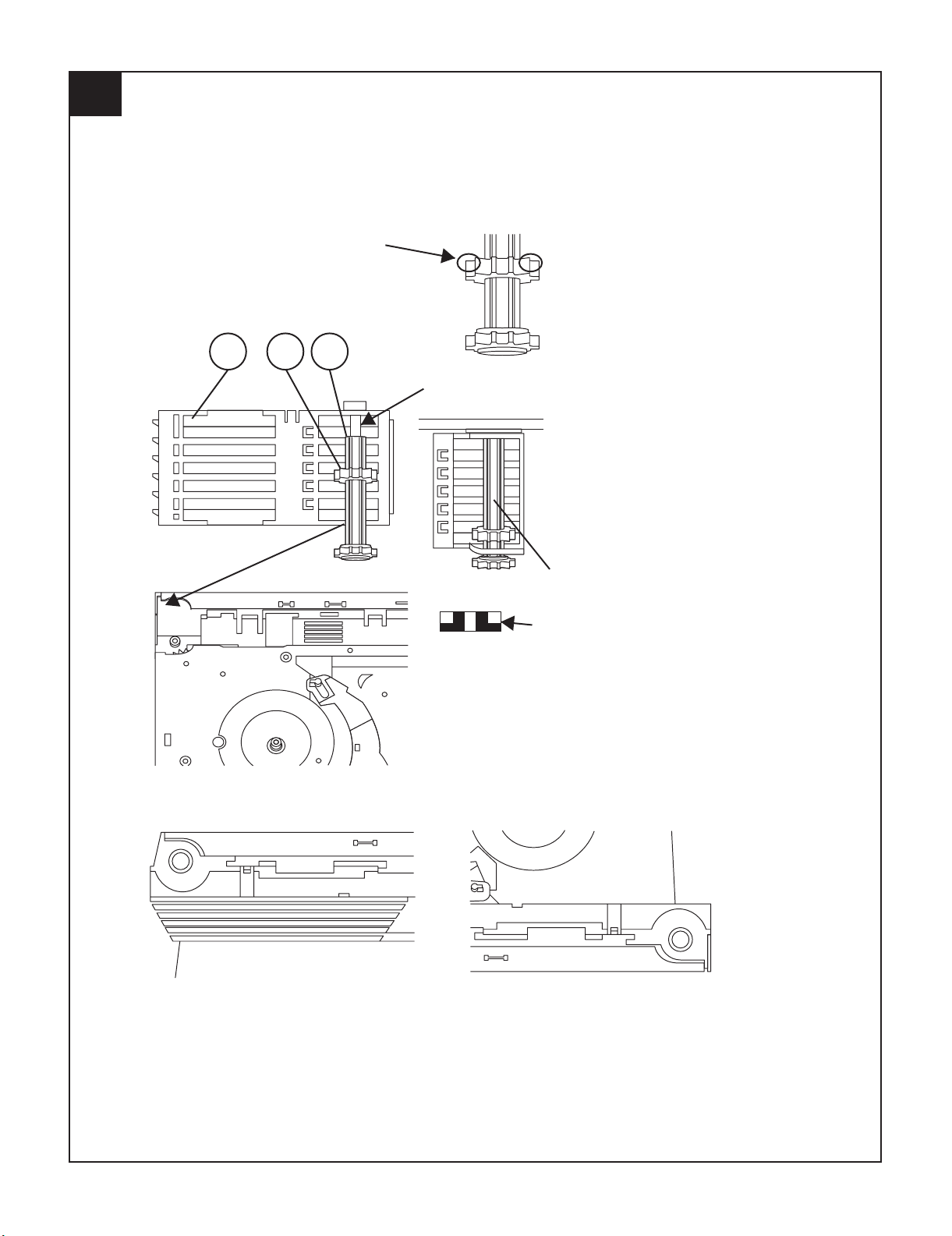
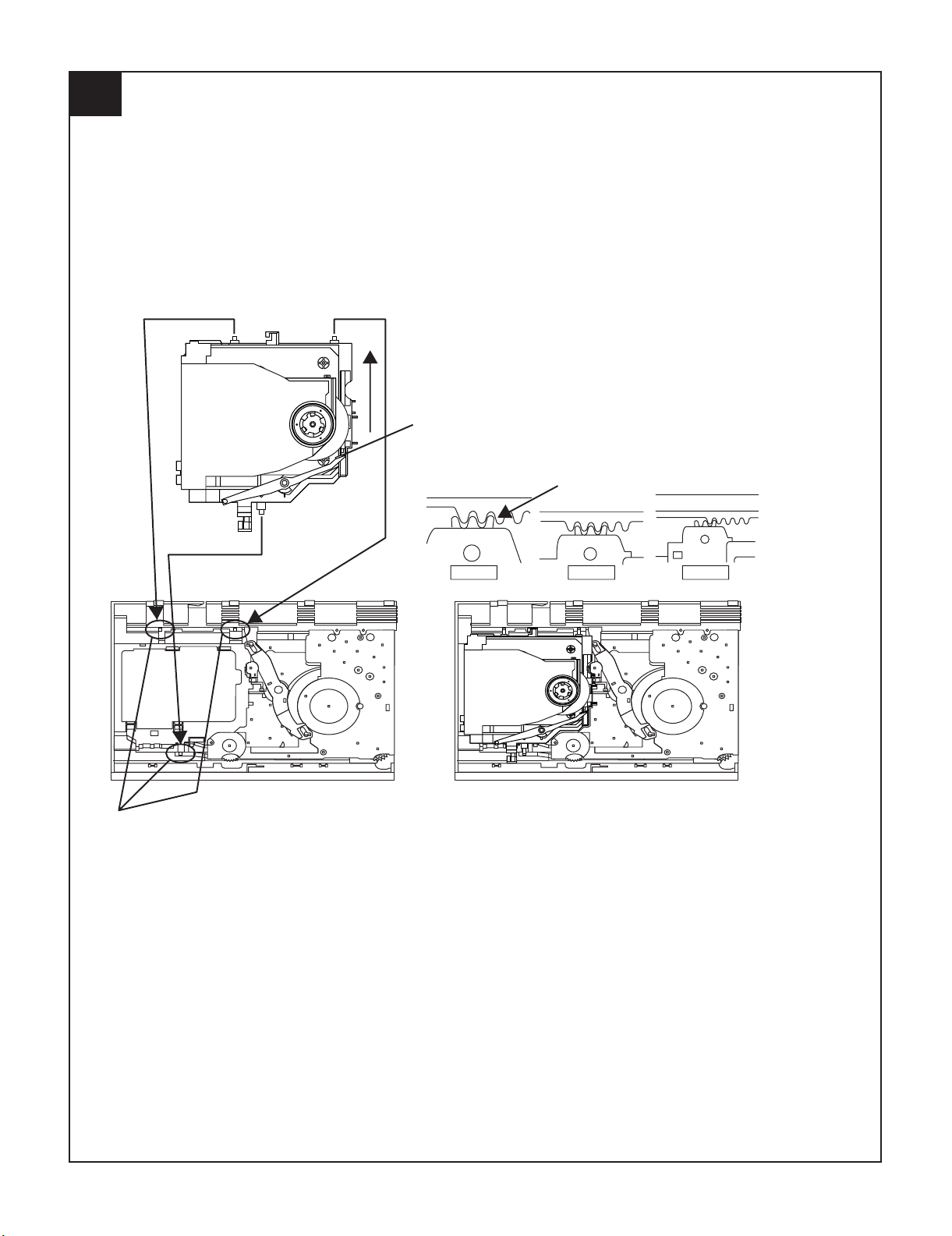
[5] CD Changer mechanism section
• A number in the drawing sheet is the number of the parts guide
(CHANGER MECHANISM PARTS).
140
141
HALF GEAR
MUST ARRANGE AS SHOWN
1
CD-MPS700
2 – 6
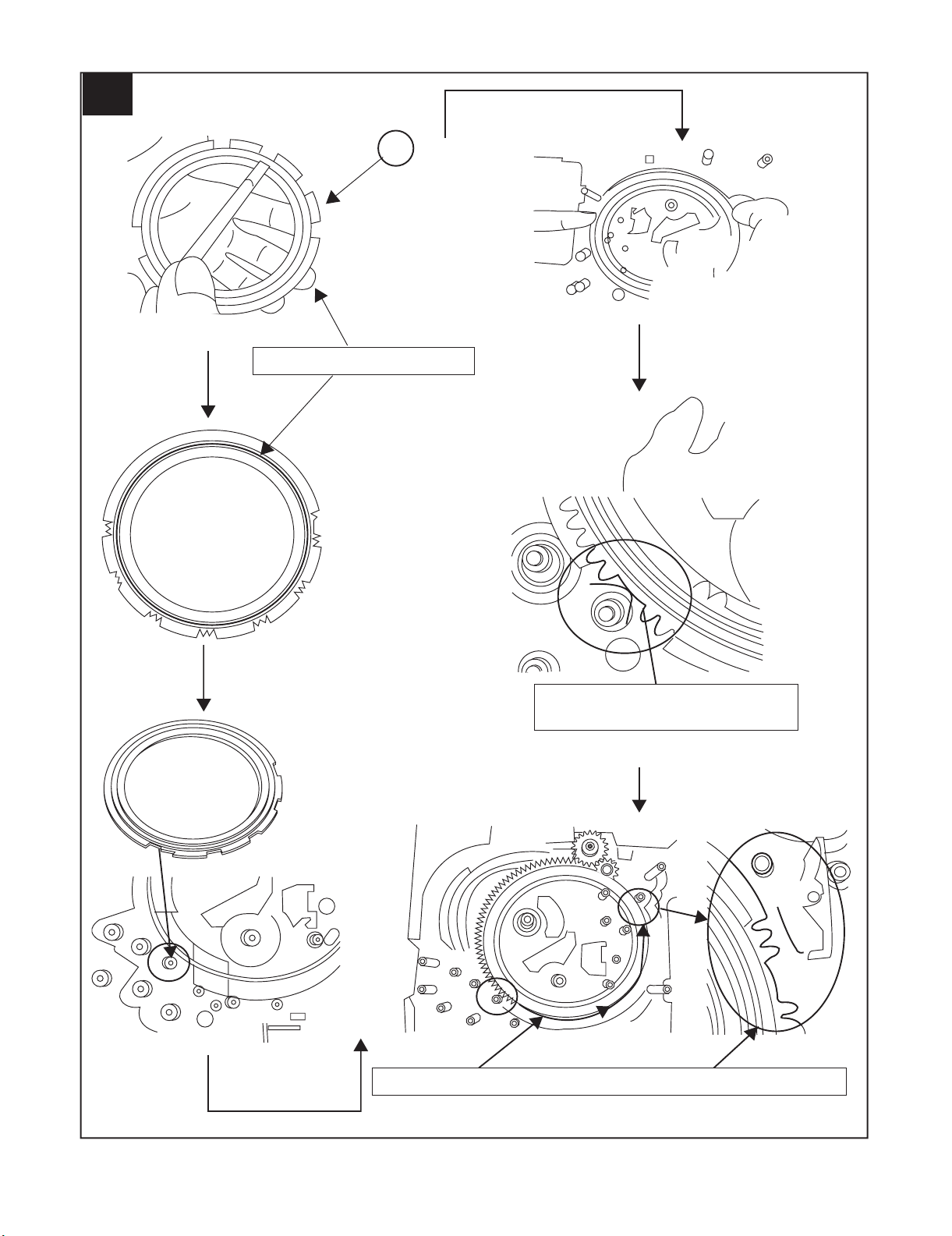
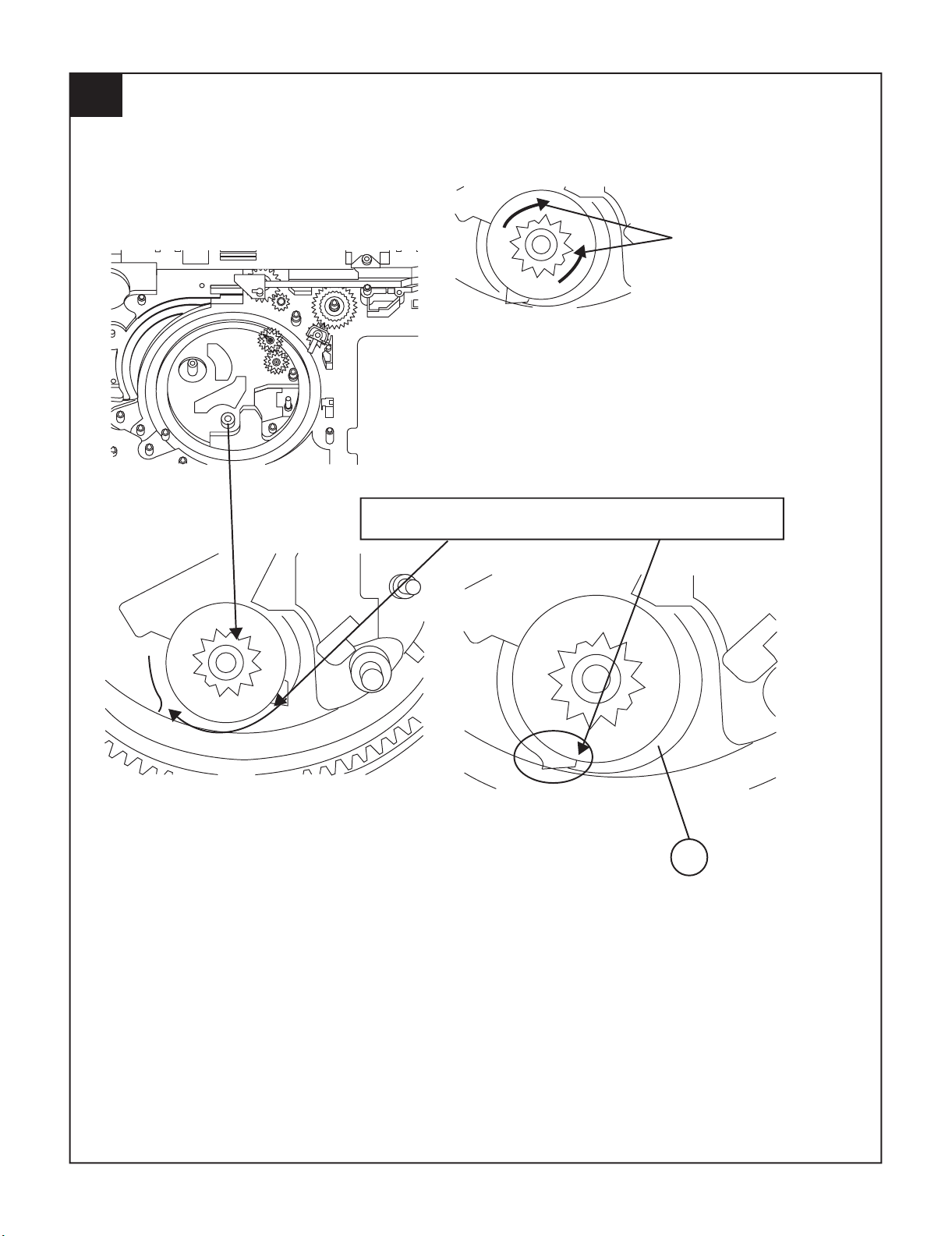
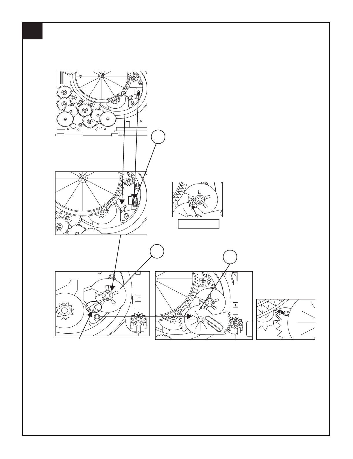
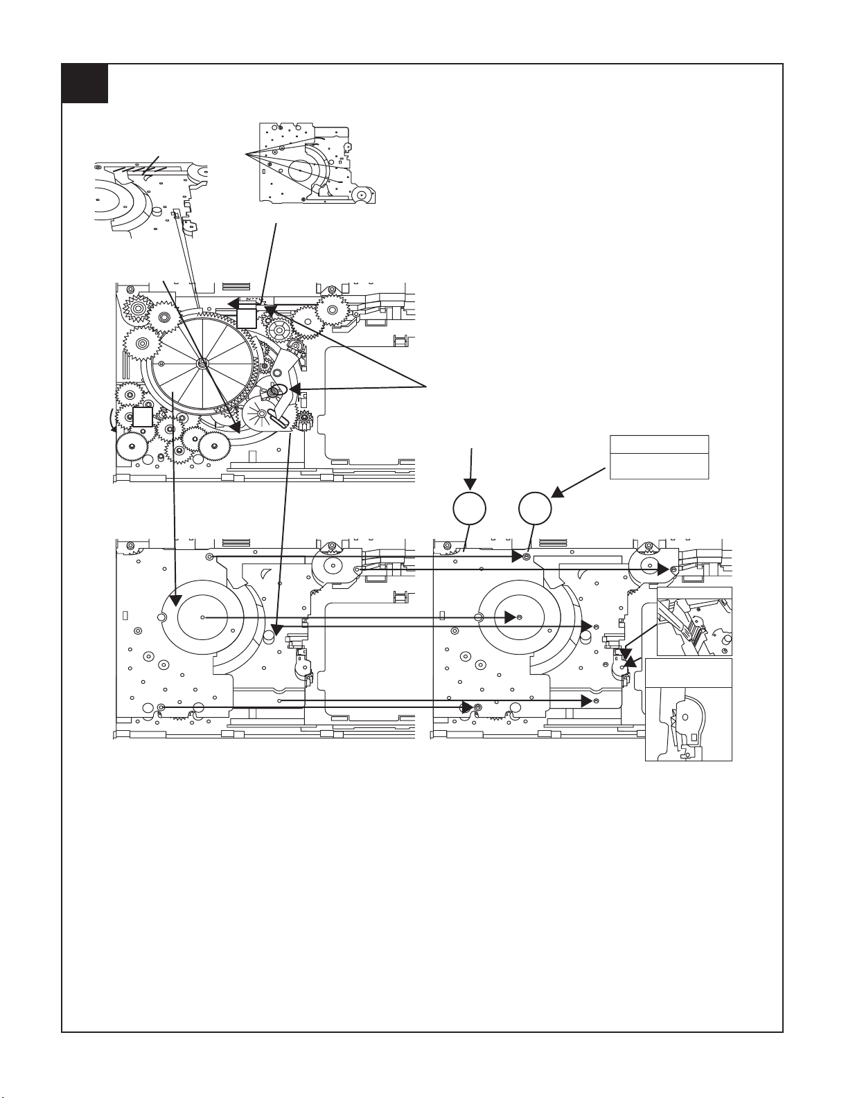
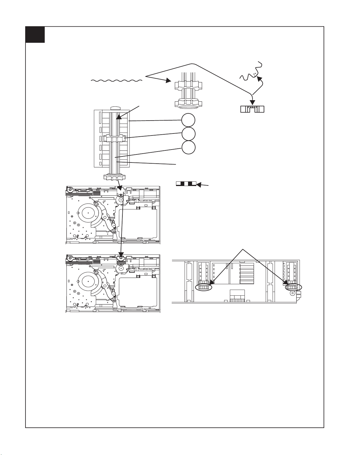
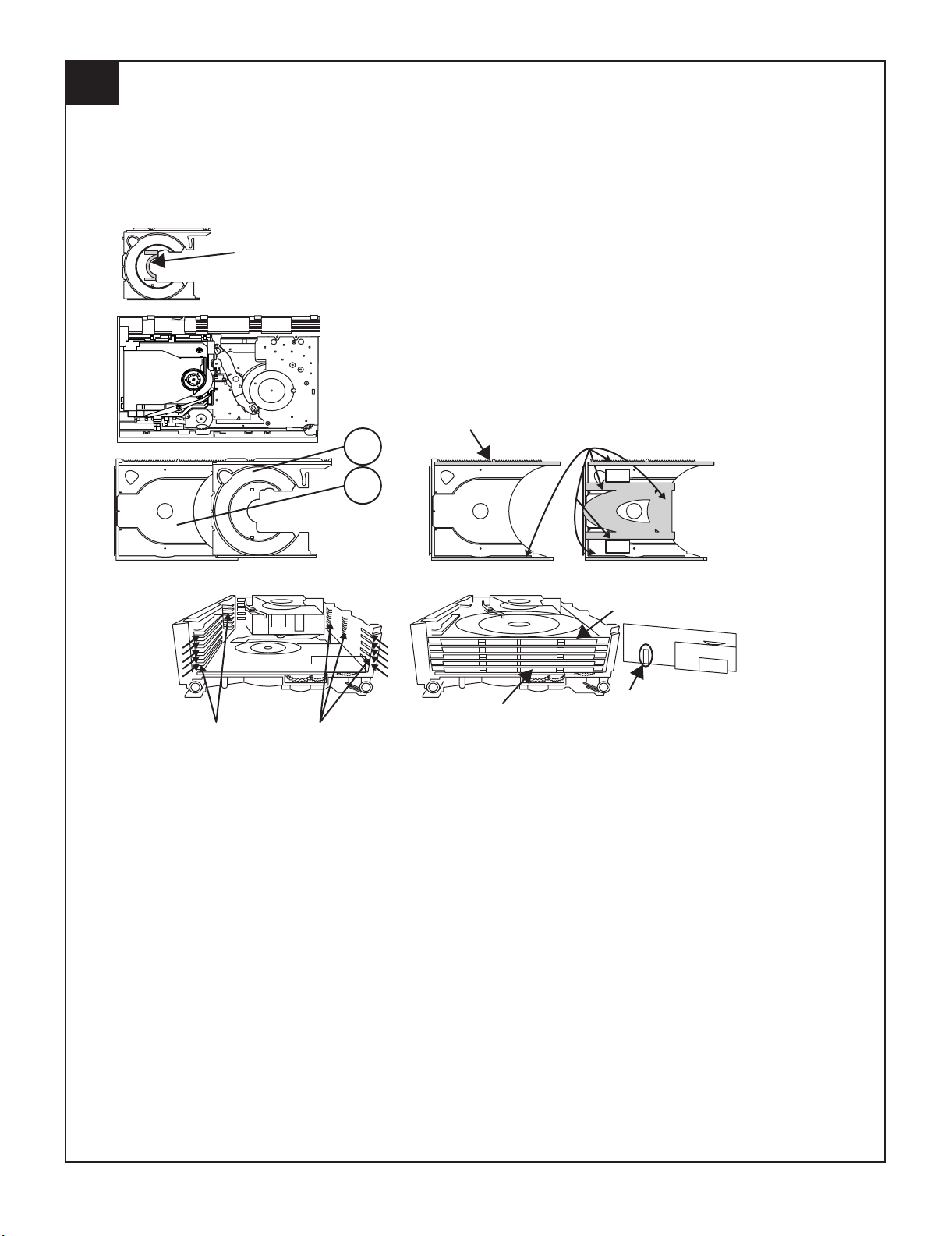
139
2
APPLY SANKOL BEFORE FIX
FIX ITEM 1 ACCORDING TO THE
SHOWN PICTURE ABOVE
ROTATE MODE BIG GEAR UNTIL REACH AS SHOWN IN PICTURE
CD-MPS700
2 – 7
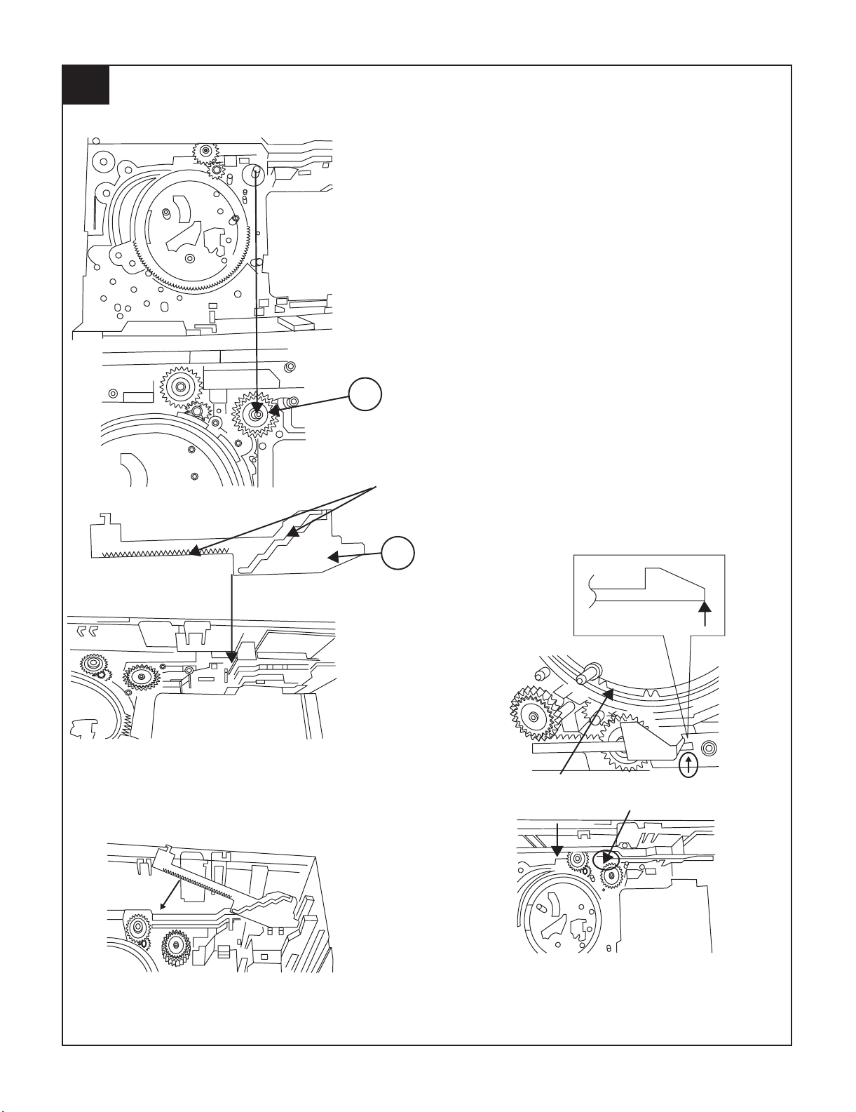
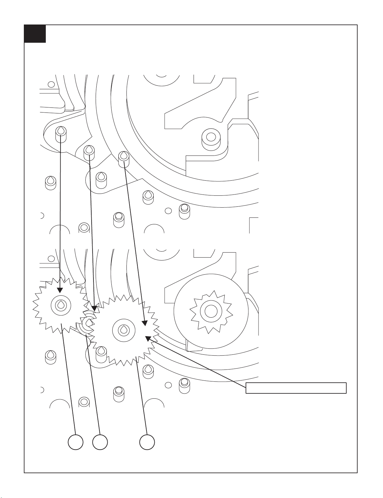
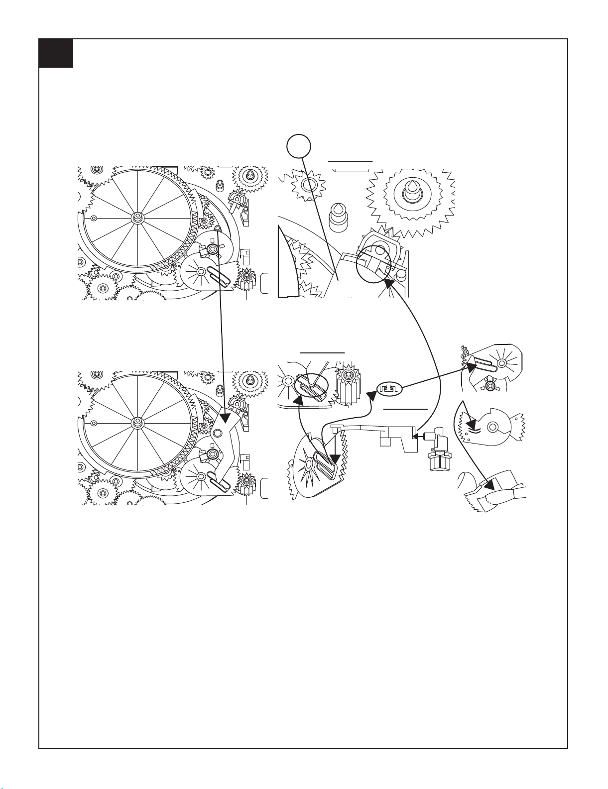
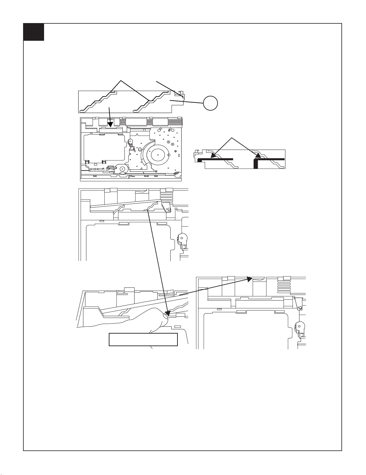
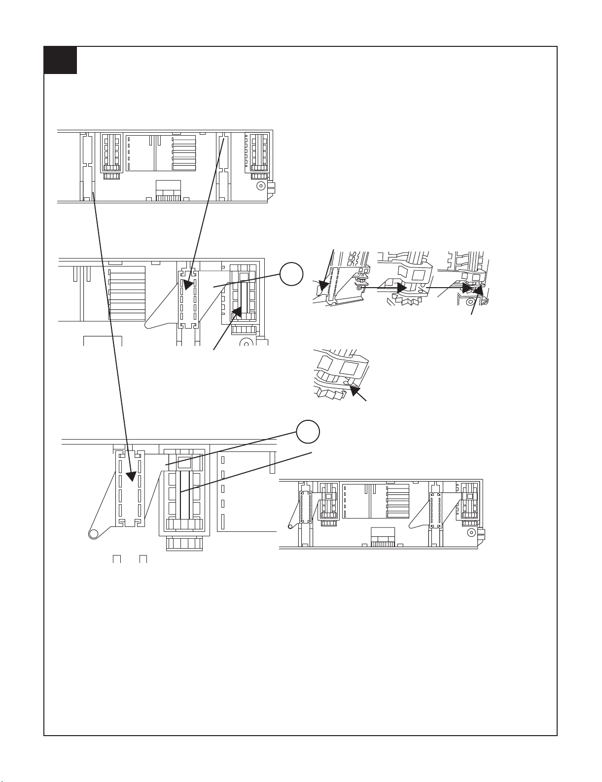
APPLY GREASE
PULL THE LEVER UNITIL
REACH THE ARROW MARK
143
112
3
CD-MPS700
2 – 8
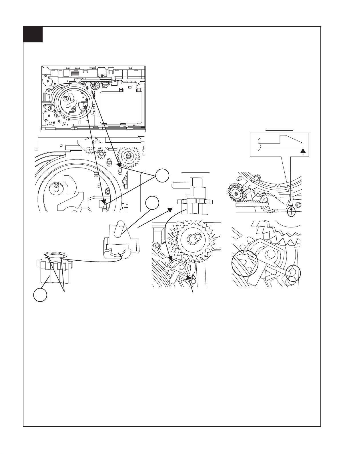
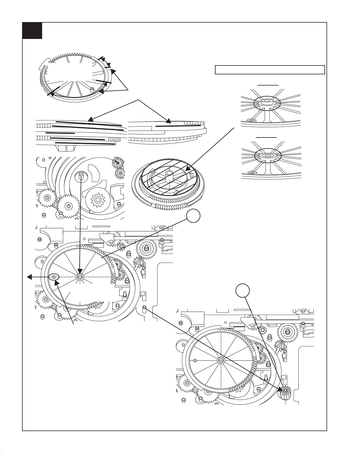
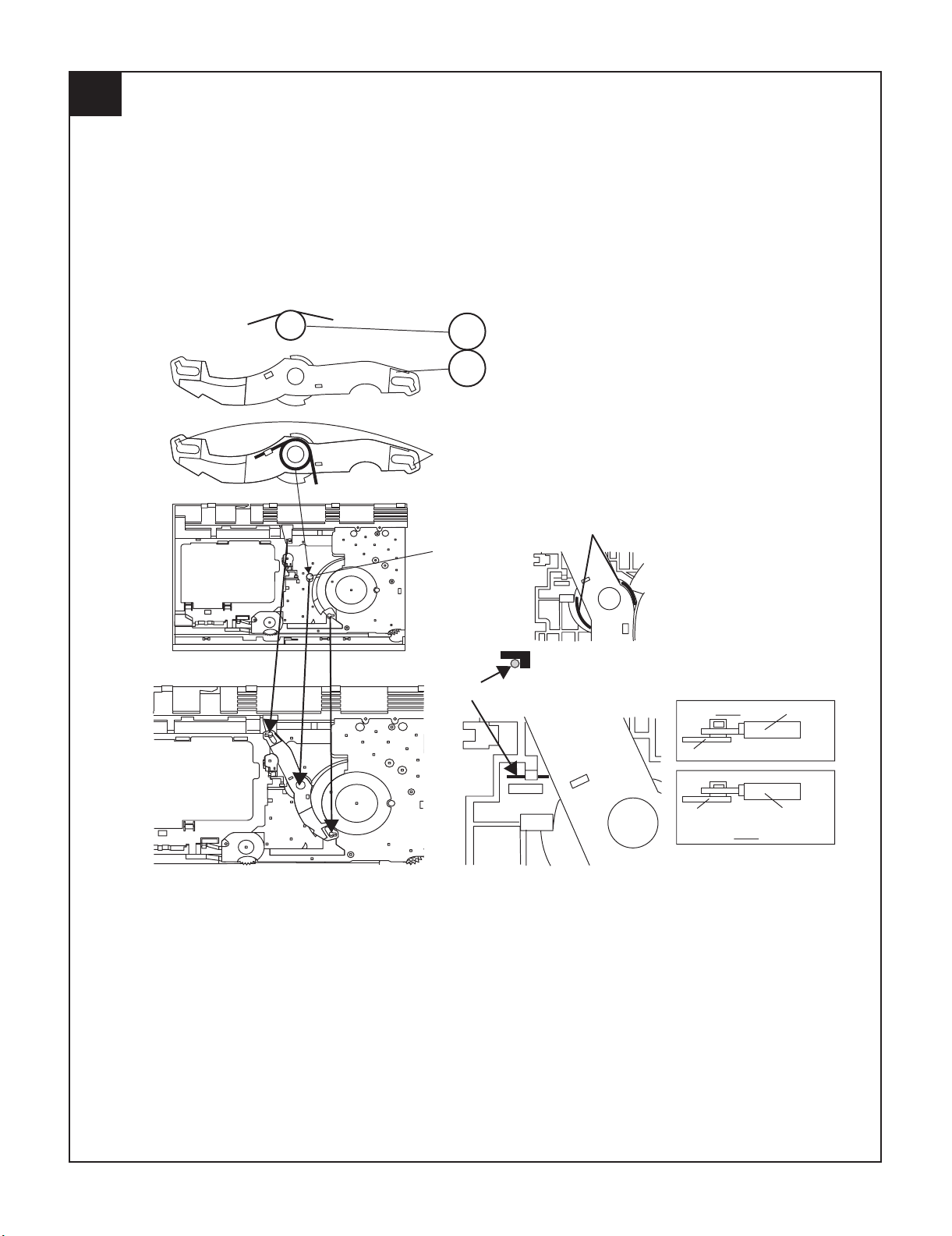
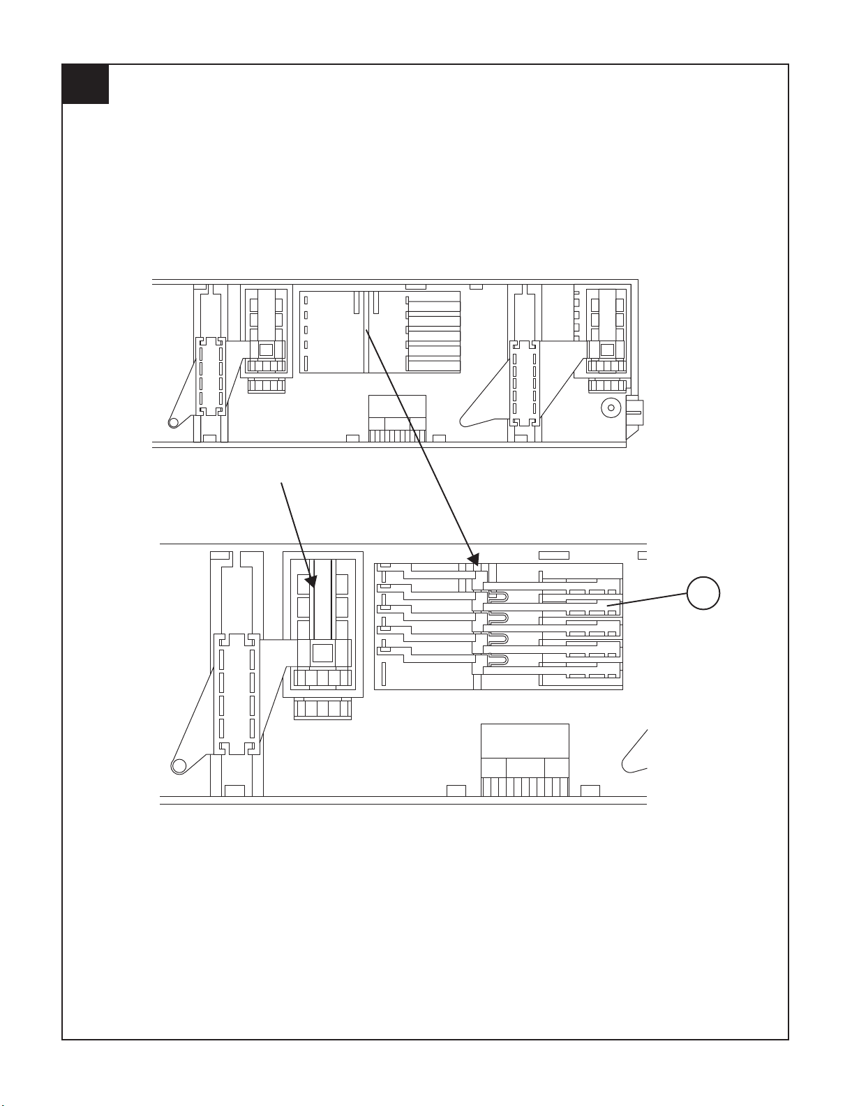
FIGURE 1
FIGURE 2
APPLY GREASE
SLOT CLAMP SW ARM INSIDE BASE SLOT
152
142
118
4
CD-MPS700
2 – 9
127
128
5
APPLY GREASE AT BOTTOM SIDE
OF GEAR FOLLOW MARKING
NO NEED APPLY GREASE AT BOTTOM
SIDE
O.K
BLACK MARK
FIGURE 1
N.G
OTHER THAN FIGURE 1 DIRECTION ALL N.G
APPLY GREASE AT
TOP SIDE OF GEAR
FOLLOW MARKING
CD-MPS700
2 – 10
APPLY GREASE AT
HALF GEAR AREA
ROTATE CLOCKWISE UNTIL REACH HERE (MAXIMUM)
6
129
CD-MPS700
2 – 11
CHANGE COLOR TO BLACK
150151148
7
CD-MPS700
2 – 12
124
131
TRAY BIG GEAR
CHANGE COLOR
TO BLACK
TRAY BIG GEAR
CHANGE COLOR
TO BLACK
GREASE APPLICATION LENGTH
GREASE APPLICATION PORTION
MUST FREE FROM GREASE THE SHOWN AREA
O.K
N.G
SHOWN HOLE MUST FACING ARROW DIRECTION
8
CD-MPS700
2 – 13
TR-RE JOINT GEAR C
APPLY GREASE AT
BOTTOM SIDE ONLY
APPLY GREASE ONLY AT TOP SIDE GEAR
MUST FIX ACCORDING TO THE HOLE'S
138 126 125
9
CD-MPS700
2 – 14
10
148 147 146 145
CD-MPS700
2 – 15
APPLY GREASE
WH EN FIXING ITEM 2 MUST FOLLOW AS SHOWN
121
144
130
11
CD-MPS700
2 – 16
FIGURE 1
FIGURE 3
FIGURE 2
APPLY GREASE SC141
APPLY GREASE
117
12
CD-MPS700
2 – 17
ITEM 2 , 3 MUST APPLY GREASE ON TOP SIDE GEAR ONLY
O.K
N.G
TOP VIEW AFTER
ASSY
FIX REVERSE N.G
GEAR 112 GEAR 112
134
133
132
13
CD-MPS700
2 – 18
APPLY GREASE BEFORE FIX
MOVE 112 UNTIL TOUCH THE WALL
DURING GEAR A ROTATE
MUST PRESS SHOWN AREA
AND LEVER B WILL MOVE
ARROW DIRECTION THEN
FIX PART 108
SCREW TORQUE
A
B
APPLY GREASE
CONFIRM WHETHER
FIXED
PROPELY OR NOT
108 803 x6
14
2 kgf-cm
+0.5
-0
CD-MPS700
2 – 19
APPLY GREASE
BEHIND THE LEVER NEED TO APPLY GREASE
PULL IT THEN LEVER WILL
MOVE IN
115
15
CD-MPS700
2 – 20
APPLY GREASE
AT BOSS
APPLY GREASE
APPLY GREASE BEFORE FIX
SPRING MUST ARRANGE UNDER THE HOOK
O.K LR JOINT LEV
LR JOINT LEV
BOARD R
BOARD R
N.G
123
115
16
CD-MPS700
2 – 21
APPLY GREASE
ASSY REVERSELY N.G
BIG SLOT MUST FACING OUT
WH EN FIX & AFTER FIX TO BASE CHASSIS
AFTER ASSY CONFIRM THE FREE DROP
GEAR POSITION DURING FIXING
103 137 136
17
CD-MPS700
2 – 22
ASSY REVERSELY N.G
WH EN FIX & AFTER FIX TO BASE CHASSIS
AFTER ASSY CONFIRM THE FREE DROP
APPLY GREASE
BIG SLOT MUST FACING OUT
GEAR POSITION DURING FIXING
CONFIRM BOTH GEAR SIT PROPELY & LOCKED
18
114
135
136
CD-MPS700
2 – 23
BIGGER SLOT FACING OUT
BIGGER SLOT FACING OUT
AFTER FIX OUTER UP/DOWN LEVER HOLD SHOWN PORTION AND
MOVE UP/DOWN THEN CONFIRM LEVER GO INSIDE THE HOLE OR NOT
IF NO GO INSIDE HOLE IS N.G
IF GO INSIDE HOLE
IS O.K
120
119
19
CD-MPS700
2 – 24
BIG SLOT FACING OUT
110
20
CD-MPS700
2 – 25
PUSH THE LEVER ACCORDING TO ARROW
DIRECTION THEN FIX
WH EN FIX MAIN BASE ASSY FOLLOW ACCORDING TO O.K PICTURE
O.K
N.G
N.G
MAKE SURE MECHA HOLDER SHAFT FIX PROPELY TO LEVER
21
CD-MPS700
2 – 26
APPLY SANKOL ON TOP
APPLY SANKOL
APPLY SANKOL INSIDE THE SLOT
& OTHER SHOWN PORTION
RIB
RIB
APPLY SANKOL AT TRAY SLIDING PORTION
FIX TRAY NO 1 FIRST THAN
FOLLOW OTHER
COSMO GUIDE TRAY HAVE
MARKING AS SHOWN
101
102
22
 Loading...