


CD~K777X
CP-K777
SHARP SERVICE MANUAL
No. SX544CDK777X1
mJD~~
DIGITAL AUDIO
CD-K777X
CP-K777
•Inthe interestsof user-safetythe setshould be restored to its original conditionand only partsidentical to those specified should be used.
INDEX TO CONTENTS
Page
SPECIFICATIONS |
|
2 |
VOLTAGE SELECTION |
,..' |
2 |
AC POWER SUPPLY CORD AND PLUG |
2 |
|
NAMES OF PARTS |
|
3 |
OPERATION MANUAL |
|
5 |
DISASSEMBLY |
|
6 |
REMOVING AND REINSTALLING THE MAIN PARTS |
8 |
|
ADJUSTMENT |
|
10 |
BLOCK DIAGRAM |
|
12 |
SCHEMATIC DIAGRAM / WIRING SIDE OF P.w.BOARD |
18 |
|
NOTES ON SCHEMATIC DIAGRAM |
40 |
|
TYPES OF TRANSISTOR AND LED |
40 |
|
WAVEFORMS OF CD CIRCUIT |
|
41 |
LCD SEGMENT |
|
42 |
TROUBLESHOOTING (DSP SECTION) |
43 |
|
TROUBLESHOOTING (CD SECTION) |
47 |
|
FUNCTION TABLE OF IC |
" |
53 |
REPLACEMENT PARTS LIST/EXPLODED VIEW
SHARP CORPORATION

CD:.K777X
CP:-K7Z7 ,-----------------------------~
FOR A COMPLETE DESCRIPTION OF THE OPERATION OF THIS UNIT, PLEASE REFER TO THE OPERATldNMANUAL' ,'-'-=~ ,-; 7 ,~~--", .)
:. ; ..
CD-K777X
• |
General |
|
|
|
Po:wer source:; ,j"" |
|
AC 110/127/220/230-240 V, |
||
|
|
|
|
SO/60Hz . |
Power consumptlon: |
....: |
.200W, |
||
Dimensions:·J |
' |
Width~270nim (10-5/8") |
||
|
|
|
|
Height; 316 mm (12-7/16") |
|
|
|
|
Depth; 329mm (12-15/16") |
Weight: |
|
|
8.0 kg (17.6Ibs.) |
|
• |
Amplifier section |
/ ... |
|
|
Output power:
Input terminals:
Output terminals:
PMPO; 400 W (total) MPO; 130 W (65 + 65 W) (10 % T.H.D.)
RMS; 80W (40W +40W) (10 % T.H.D.)
VIDEO/AUX (audio signal); 500 mV/47 kohms VIDEO/AUX (video signal) VIDEO/AUX (audio signal);
.'-,-; ,.5GOmV(4Tkohma,...,
.\iiD.Ed/AUX (V!deoslgna.l) SpeakEirs;'8'bhtris',,"
Headphones; 16-50 ohms (recommended; 32 ohms)
.i J ·, ,'
• Compact disc player section
Type:
Signal readout:
Rotational speed: Error correction:
Quantization:
Filter:
DIA converter: FreCluency response: Dynamic range: Wow,and flutter:
s-otscmulti-play compact disc player
Non-contact; 3-beam semi-con ductor laser pickup
200 - 500 rpm CLV, Approx. CIRC (Cross Interleave ReedSolomon Code)
16-bit linear s-tlrnesoversaropnnq a.igital filtE\r, t-blt D/A converter ', .. c
20 - 20,000 Hz
90 dB (1 kHz) Unmeasurable
(lessthan 0.001% Wpeak)
.~
• Tuner section |
|
Frequency range: |
FM; 8$':-TmfMHz |
|
AM; 531 "1 ,602kHz |
• Cassette deck section
Type:
Frequen¢y response:
Motor: '
Signal/npise ratio:
Bias and erasuresystem:
Tape speed: Wow and flutter: Heads:
CP-K777
• Speaker section
Type:
Rated input power: Maximum input power: Impedance: Dimensions:
Weight:
. ..
Compact cassette tape
50 -14,000 Hz (Normal tape)
50 • 15,000 Hz (Cr.02 tape) : DC motor with electronic governor xl
55 dB (TAPE 1, playback)
50 dB (TAPE 2, recording/
'playback).
. AC
4.76em/sec (1-7/8 ips.)
0.15% (WRM$.)." '''',, . TAPE-l: Piaybackx,1'j " i;
TAPE-2; Rec9r~lplaYJ;>i3"?I<*:li;
Erase x 1" .,)' .
u rj
3-way, Type [160 mm(6-1/2") woofer and 50 mm (2") tweeter and super tweeter]
40W
80W
B ohrns
Width; 210 mm (8-1/4") Height; 316 mm (12-7/16") Depth; 309mm (12-3/16") 4.9 kg (10.8 ibs.)/each
Speci'ticai,6rikfor this model are subject to change without prior notice.
.
VOLTAGE SELECTION
Beforeoperationg the unit on mains, check the preset voltage. If the voltage is different from your localvoi~age.sUde,th~\.h.Cpower supply socket cover by slightly loosing the screw to the visible indlcationofthe slde',pfypur 10c~1 )/9Itage.,,: .
QACGA0001AWOO 92LPLUG027 ,:
, J f ~.__';'Ij.;
QAC<DB0001 AWOO
QACCE0001 AWOO |
"/'.:'. |
|
'92LPLUG155A
92LCoRDA1387C
III |
I\ |
92LCoRDT1699A
_L,==<
Figure2-AC POWERSUPPLY CORIJAND ACPLUG ADAPTOR
:I..J |
'..[ - ~ |
.,. |
i; |

CD~K777X
CP~K777
NAMES OF PARTS
CD·K777X
•Front panel
1.Disc Tray
2.Disc Number Select Buttons
3.Disc Skip Button
4.Open/Close Button: ~
5.Music Schedule Indicators
6.Random Indicator
7.Memory Indicator
8.Timer Indicator
9.Extra Bass Indicator: X-BASS
10.Record Indicator
11.Karaoke Maker Indicator
12.Disc Number Indicator
13.Sleep Indicator
14.Frequency/CD CounterlTimeiSleep Time Indicator
15.CD Repeat Indicator: c
16.FM Stereo Indicator: OJ.
17.FM Stereo Mode Indicator: ST
18.Function/CD Track/Preset ChannelNolume Indicator
19.CD Pause Indicator: II
20.CD Play Indicator: ~
21.Spectrum Analyzer/BalanceNolume Level Indicator
22.Digital Signal Processor Indicator
23.Remote Control Sensor
24.Power Switch
25.Function Selector Buttons
26.Equalizer Selector/Demo Mode Button
27.Extra Bass Button: X·BASS
28.Volume Up/Down Buttons: /'Jv
29.Digital Signal Processor Buttons
30.Headphones Socket
31.Record Start Buttons
32.Clock Button
33.Sleep Button
34.Timer Button
35.Memory/Set Button
36.Tuning and Time Up/Down Buttons: A/V
37.Stop Button: •
38.PlayJRepeat Button: ~
39.Track Up/Cue/Preset Up Button: ~
40.Track Down/Review/Preset Down Button: -+011
41.CD Pause Button: II
42.Digital Echo Control
43.Microphone Level Controls
44.Microphone Sockets
45.Karaoke Maker Switch
46.(TAPE 1) Cassette Compartment
47.(TAPE 2) Cassette-cCompartment-
1 2 3 4
I I I
(0 0 OJ 6~
~
.>:
11 |
12 |
13 |
14 |
1516 17 |
|
18 19 20 21
2423 |
22 |
25 2627 28 29
303132333435363738
45 44 434241 4039
46 47
-3-
CD:K777>C
CP~K77'7j
|
|
|
|
|
|
.J .J |
• |
Rear panel |
|
|
|
|
|
|
1. FM 75~ohms Aerial Terminal |
|
||||
|
2. |
Aerial 'EarthTerillinal |
: |
|
||
|
3. |
AM,l,;;dopcAerial Socket:····I |
. 'I |
|||
|
4." ResetsUtt':'f1" |
'" |
L |
,.1 |
||
|
1.5. Span Selector'Switch- - |
|
" |
|||
|
6. |
Video/Auxiliarr(AUdioSlgna.l) inputSockets! |
||||
|
~7,Video/Auxlllary(Video,Sign~I),.,lnPlltSC!~l<e!".i |
|||||
|
0: VideolAu:idliary (Video"Signaij Output Sock-et',. |
|||||
|
9. ,Video/Auxiliary,(Audio Signal) .,OutputSockets |
|||||
|
, |
|
|
|
|
\ |
10. Speaker Terminals."··,,,: |
||||||
1 t, |
AC Power Lead'·\, |
|
' |
|||
12. AC Voltage S~lector |
|
|
||||
.iSpeaker section' |
|
|
|
|||
1~. Tweeter |
|
|
|
|
||
14. Super Tweet~r(! , |
|
|
||||
15. |
Woof~c |
. J |
|
|
|
|
16. ,Bass Reflex Dut:t', |
|
|
||||
1~. :SPeaker Wire ,~ |
, |
|
|
|||
• |
•Remote qO!1tr~l< |
|
'.' j |
|
||
|
; |
, . "\ |
v.' __: .. J |
j |
||
18.R~moteCQ.ntrgJ TrimsmitterWindow |
||||||
• |
Tuner control section |
|
|
|||
19. Preset, Up/Down Buttons: VIA |
|
|||||
• |
I |
|
|
|
|
|
CD control section " |
|
|
||||
20: Tiack oi»wn/Review:Buttom ....... /1-+lI 21,'lracl<up/Cue 'Butto~;._~ j:~
22LOiscNurtibet,Seiet t,$uttons" "",:, .. ,. 23. DisclSkip Butto'n I
24.Play!~~peata:Yt!9n:-~?:';":' ,.'
25.Stop Button: •
26.Memory Button
27.Clear Button
28.Random Button
2~[~aJ~e:.Bu~qn:)i:, ,c'
• tape co',1'trors~ction.'
30. &APE~~)Bevl,.in~BLltt~n~~
3~. trAPE 2>:FastForWar~'~utto,:,:.~
32./(TAPE 2) ,Stop'.'Bunon:.•'.: "
33~:(TAPE2) play·Btitt6ii:;~ |
",,<c,' |
|
||||
f |
_, |
I |
.; |
J |
|
|
3,4. (TAPE 1lSto~ Button: • |
," |
'.'. |
||||
35.,'(TAPE1) piayButttin:'.... |
" |
-"j |
||||
|
|
|||||
36.Digital Signal Processor Buttons, (SURROUND)
37.Volume Up/Down Buttons: vIA; '" 38.Balance Control'Buttons
39.: function Selectqr Buttons 40.: Equalizer Mode Buttons
41.: |
Power Bulton |
-i |
42. |
Extra Bass Button: X·!3ASS |
|
1
2 " "."] ~:
3_---#__~rm~~~~o:::'.J;~'"~~'~:~ii"}:~~~.~~
9 .
lI-+-..IfJll-----:'-:--...II,;. ;"',;J,:J~,!,;:ii',:
i'.';'"7:«JT1::lF} .,B
14
15 |
,o,['J"1 |
j-,.- |
16
':1" :
|
|
" |
|
|
|
|
|
|
26272829 |
|
|
|
|
||
|
|
|
i")~~''-:.::.1.J. 1,.:"'1 ].', |
|
|
|
|
|
30 31·3-2'133">:',,' |
|
|
|
|||
|
|
|
|
d:,'34:' |
-"~'; |
|
|
|
|
|
|
|
T. |
|
|
38 |
|
=:.l-==-=~="'=;:~U--;,-:-'! .,,;- ,: |
|
-- ,> |
|
||
|
~ |
',',.- |
|
||||
|
.!:::::::!,J:===4:::::::!.I-!=~:i!tt"'"',,;...;..,i35i i |
|
|
||||
39 |
|
|
|
||||
|
|
|
';j"'/·'L:-',;-,i':.'),"JJ |
|
|||
|
|
|
|
|
|||
40" |
|
|
|
|
|
|
|
41 |
|
|
|
|
|
|
|
:>42'.;..".-:~~ |
|
|
|
|
|||
|
I.=:====~~ |
|
, -..-. |
|
|||
|
!~'. _.' _ .. __ .' |
'>i |
|
|
|||
|
,,'):, |
.'J,' |
|
||||
|
.,-..,' |
.'- |
|
||||
|
|
|
|
|
|
|
|
|
|
|
|
|
|
|
|
-4-
I
01
1
'SETTINGTHE CLOCK
|
lin this exaMple, the clock is set for |
the |
|
|
|
|
|
|
|||||||||||||||
|
2.4-hour (0:00) |
system. |
|
|
, |
, |
|
, , |
|
|
|
|
|
||||||||||
|
, |
|
|
|
|
|
|
|
|
|
|
|
|
|
|
||||||||
|
|
|
|
|
|
|
|
|
|
|
|
|
|
|
|||||||||
|
|
|
|
|
|
|
|
|
|
|
|
|
|
|
|
|
|
||||||
|
|
|
|
|
|
|
|
|
|
|
|
|
|
|
|
|
|||||||
|
|
|
|
|
|
|
|
|
|
|
|
- n |
-I |
I |
11- |
|
|
|
|
|
|||
|
|
, |
|
, |
|
I |
|
I |
-U '11 I J - |
/ |
|
|
|
|
|||||||||
|
|
|
|
|
/1' |
11-1 |
II' |
|
|
|
|
||||||||||||
|
|
; |
|
|
|
|
|
|
|
|
|
|
|
|
|
|
|
|
|
|
|
|
|
|
|
|
|
|
|
-I- |
I |
1-/ |
t: |
II - |
|
|
|||||||||||
|
|
I |
|
-I |
I |
|
U |
|
I |
|
|
r\ |
,- |
|
|
|
|
||||||
|
|
|
|
|
|
|
|
|
|
||||||||||||||
|
|
|
|
|
|
|
|
I |
|
I |
|
I |
I |
I I |
|
|
|
|
|
||||
|
" |
|
|
|
|
|
|
|
|
|
|
|
|
|
|
|
|
0= |
|
|
|
|
|
|
|
|
|
|
|
|
|
|
|
|
|
|
|
|
|
|
|
|
|
|
|
|
|
|
|
|
|
|
|
|
|
|
|
|
|
|
|
|
000 |
|
|
|
|
||||
|
EMOFlYI |
|
|
|
==::::::i |
I- |
|
|
|
|
~ |
|
|
|
|
||||||||
|
|
|
|
|
|
|
|
|
|
|
|
|
|
|
|
||||||||
|
S ET |
|
|
|
|
|
|
|
|
|
|
|
lIQ |
|
|
|
|
||||||
|
CLO¢K |
|
|
l"GIo |
|
|
|
|
|
|
|
|
|
|
|||||||||
|
\: |
|
|
|
|
|
|
|
|
|
|
|
|
~,~ |
|
|
|
|
|||||
|
TUN ING |
|
|
|
(o~ |
|
|
|
|
|
|||||||||||||
|
DOWN |
|
9 |
|
|
|
|
|
|
|
o'3l |
e~ |
|
|
|
||||||||
|
|
UP |
|
0 |
|
|
|
|
|
|
|
|
|
|
0 |
|
|
|
|
||||
|
|
|
|
|
|
|
|
|
|
|
|
|
|
|
|
|
|||||||
|
|
|
|
|
|
|
|
|
|
|
|
|
|
|
|
|
- |
~)~ |
|
|
|
||
|
|
|
|
|
|
|
|
|
|
|
|
|
|
|
|
|
|
|
|
||||
|
|
|
|
|
|
|
|
|
|
|
|
|
|
|
|
|
|
|
|
|
|||
|
1 |
|
|
|
|
|
|
|
|
|
|
|
<n :'1 n' |
|
|
|
|
|
|||||
|
|
|
|
|
|
|
|
|
|
|
|
-U'uu- |
|
|
|
|
|
|
|||||
|
|
|
|
|
|
|
|
|
|
|
|
I |
I |
I |
" |
|
|
|
|
|
|
||
|
|
|
|
|
|
|
|
|
|
|
|
|
|
|
|
|
|
|
|
|
|
|
|
|
2 |
|
|
|
|
|
|
|
|
|
|
|
'n 'IIn' |
|
|
|
|
|
|
||||
|
|
|
|
|
|
|
|
|
|
|
|
-u·uu- |
|
|
|
|
|
|
|||||
|
|
|
|
|
|
|
|
|
|
|
|
, I |
I |
I |
I'" |
|
|
|
|
|
|||
|
|
rv -rv n |
--+ |
|
|
|
|
|
|
|
|
|
n·nn |
|
|||||||||
|
|
W ,u U |
+- |
|
|
|
|
|
|
|
|
|
u·uu |
|
|||||||||
|
|
Ii |
|
t. |
|
|
|
|
|
|
|
|
|
|
|
|
|
|
|
|
|
||
|
31:'I |
|
|
|
|
|
|
|
|
'-('11Ii |
|
|
|
|
|
|
|||||||
|
|
|
|
|
|
|
|
|
-U-·U U |
|
|
|
|
|
|
||||||||
|
|
|
|
|
|
|
|
, " |
|
|
|
|
|
|
|
|
|
|
|||||
|
|
|
|
|
|
|
|
|
|
|
|
|
|
|
|
|
|
|
|
|
|
||
|
|
|
|
|
|
|
|
|
|
|
|
|
|
|
|||||||||
|
411_~-,b;---_ |
|
|||||||||||||||||||||
|
5'1I'_-~=H=:/,I tr.;- _ --- |
|
|||||||||||||||||||||
|
6!1 |
|
|
|
|
|
|
|
|
|
I ' I.~ |
u |
|
|
|
|
|
|
|||||
|
7il---- |
|
|||||||||||||||||||||
|
|
|
|
|
|
|
|
|
|
|
|
|
|
". |
I |
|
I" |
|
|
|
|
|
|
|
|
|
|
|
|
|
|
|
|
|
|
|
|
|
|
||||||||
|
+0 switcH Ithe |
time display between the 12-hour |
|||||||||||||||||||||
|
~i"nd 24-h~pr modes: |
|
|
|
|
|
|
|
|
|
|
|
|
||||||||||
Set the *OWER switch to STAND-BY.
Disconn~ the AC power lead from the AC socket.
:3 Press t~~ RESET button on the rear panel for at least !10 seconds.
Ii
I connect,lthe AC power lead.
5 performl~teps 1 - 7 above.
,'1
•When the AC power lead is first connected, the clock indicator will flash at "0:00 CLOCK".
1 Press the MEMORY/SET bullon.
2 Press the TUNINGITIME (DOWN or UP) bullon to select the urne cflsplay.
"0:00" |
..... |
The 24-hour display will appear. |
|
|
(0:00 - 23:59) |
"AM 12:00"..... |
The 12-hour display will appear. |
|
|
|
(AM or PM 12:00 - 11:59} |
"AM 0:00" ..... |
The 12-hour display will appear. |
|
|
|
(AM or PM 0:00 - 11:59) |
3 Press the MEMORY/SET button.
4 Press the TUNINGfTlME (DOWN or UP) button to adjust the hour.
•Press the TUNINGfTlME button once to advance the time by 1 hour. Press for more than 0.5 seconds to advance continuously.
•When the 12-hour display is selected, "AM" will change automatically to "PM".
5 Press the MEMORY/SET button.
6 Press the TUNINGITIME (DOWN or UP) button to adjust the minutes.
•Keep the button pressed for more than 0.5 seconds to
make the time change in 5 minute mtervals,
•The hour setting will not advance even if minutes advance from "59" to "00".
7 Press the MEMORY/SET button.
•The clock starts nparatinq from '0" seconds. (Seconds are not displayed.)
Note:
•In the event of a power failure or when the AC power
lead is disconnected, the clock display will go out. When fhe AC power supply is resumed, the clock display wiU flash on and off to indicate that the time must be
reset.
If th',s happens, followthe above procedure, starting from step 1.
To change the clock time:
1 Press the CLOCK button. Then, within 5 seconds, press the MEMORY/SET button.
•If the next step is not pertorrnad within 5 seconds, the display will go dark.
2 Perform steps 4 - 7 above.
To look at the time display:
Press the CLOCK button.
• The time display will appear for about 5 seconds.
PREPARATION FOR USE
0.2 m - 6 m (8" - 20')
RESETTING THE MICROCOMPUTER
fl
DEMO MODE
EQUAlIZER( DEMO)
00 o 0
• Proper use of the remote control
Aim the remote control at the remote control sensor within 3D't>. with no obstacles, and operate as shown.
Notes concerning use:
•Replace the batteries if control distance decreases or operation becomes erratic.
•Periodically clean the transmitter window on the remote
control and Ihe sensor on the main unit with a soft cloth.
•Exposing the sensor on the main unit to strong light Can intel1ere with operation. Change the lighting or the direction of the unit
•Keep the remote control away from moisture, excessive heat, shock, and vibrations.
•The remote control's usable range is between 0.2rn (S") and 6 m (20'.away from the sensor-
Reset the microcomputer by performing the following procedure lor the eases shown below:
• To erase all of the stored memory contents. or
• If the display does not function property, or
•The unit does not operate properly.
1 Set the POWER switch to STAND-BY.
2 Disconnect the AC power lead from the AC socket.
3 Press the RESET bullon for at least 10 seconds.
When the power is first tumed on, the unit will be in the demonstration mode. When ttle unit enters the demonstration mode, each of the displays, Equalizer, X-BASS, Digital signal processor and Music calendar, will be lit, in order. .
To cancel the demonstration mode, tum off the power. Whilst pressing the EQUALIZER (DEMO) button, tum on the power.
o
"'tJ
m
J]
o~ z
3:
»
z
c:
»
r-

CO...K771X
.·,P'o;K77V' |
|
C J- _ ,' _ ..j. ... 1 |
|
Caution on Disassembly |
,. ,.,- |
Follow the below-mentioned notes whed disassembling the unit and reassembling it, to keep it safe arig E;!nstire excellent
performance: " ",'",'
1, Take cassette tape and compact disc q!Jt qf:th~ uniY:
2.Be sure to remove the power supplY-'ph..\gfrornthe wall outlet before starting to disassemblethra:,uni£.j
3.Take off nylon bands or wire holders wl'i~re;theyneed be removed when disassembling the uni# ~ffe'rservicing~the
|
unit, be sure to rearrange the lead~\!'Ihere,they w,ere |
|
|
|||||||||||||||||||||||||||
|
before disassembling. |
|
|
|
|
|
,,'Ci |
",' |
;',:.c, |
, |
|
|
|
|
|
|||||||||||||||
|
4. Take suffcient care on static electricity ofi,nt~gf1:jJedcirc~its |
-! |
|
|||||||||||||||||||||||||||
|
and other circuits when servicing. |
|
""" "~ |
|
|
|
|
|
|
|||||||||||||||||||||
|
|
CD-K777X |
|
|
|
|
|
|
|
|
|
|
|
|
|
V~ |
" |
, |
|
-: |
|
|
|
|
|
|
||||
|
|
|
|
|
|
|
|
|
|
|
|
|
|
|
|
|
',J |
|
: |
|
|
|
|
|
||||||
|
|
|
|
|
|
|
|
|
|
|
|
|
|
|
'-' |
|
|
|
|
|
|
|
|
|
||||||
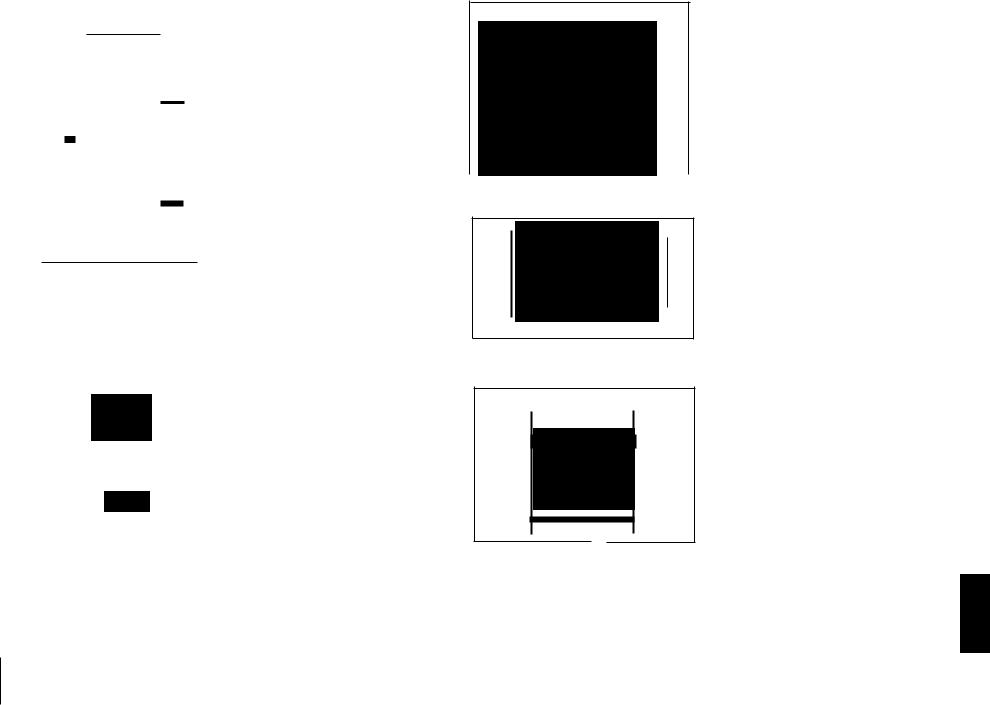
|
STEP |
REMOVAL |
|
|
|
PROCEDURE |
|
|
|
FIG,URE |
|
|
||||||||||||||||||
|
1 |
Top Cabinet |
|
|
|
1. Screw |
....................... |
|
|
|
|
|
|
|
(A1) x4 |
6-1 |
|
|
|
|
||||||||||
|
2 |
Side Panel |
|
|
|
|
1. Screw |
....................... |
|
|
|
|
|
|
|
(B1) xB |
'B-1 |
|
|
|
|
|||||||||
|
|
|
|
|
|
|
|
|
|
|
|
|
|
|
|
|
|
|
|
|
|
|
|
|
, |
|
|
|
|
|
|
3 |
CD Player Unit |
1. Turn on the power supply, |
6-1 |
|
|
|
|
|
|||||||||||||||||||||
|
|
|
|
|
|
|
i |
-- |
,r.open,;thedip,ctra,y,take |
|
|
|
'! |
|
|
|
|
|
||||||||||||
|
|
|
|
|
|
|
I:, outtHetray,panel, ana |
|
|
|
! |
|
I |
|
|
|||||||||||||||
|
|
|
|
|
|
|
i I, |
Grose, (N6te 11 |
I!'i, 'i:: |
:i |
|
|
|
|
||||||||||||||||
|
|
|
|
|
|
|
|
2. Socket |
|
|
,...•".·.'.i'.r..•. (Cl) x2 |
, |
|
|
|
|
|
|||||||||||||
|
|
|
|
|
|
|
|
... |
|
|
|
|
|
|
||||||||||||||||
|
|
|
|
|
|
|
|
, $.:Hook .. |
....;.: |
\..f.i);..;.iJ,(C2) x2 |
|
|
|
|
|
|||||||||||||||
|
4 |
Back |
Board |
|
|
|
|
11. Screw ,....... ~... |
,..i).... |
|
!.,. (01) xB |
6-1 |
|
|
|
|
|
|||||||||||||
|
|
|
|
|
|
|
|
! '. ' . , |
|
_ . ' . |
|
|
|
|
|
|
|
|
|
|||||||||||
|
5 |
Main PWB |
|
|
|
I |
t. |
,Screw .. |
|
" .i.,»::'... |
!,••,.... (E1) x5 |
6-2 |
|
|
|
|
|
|||||||||||||
|
|
|
|
|
|
|
|
Z., SockeL .. |
|
,...... ;.;..;..... |
|
|
L.·(E2)xB |
, |
|
|
|
|
|
|||||||||||
|
|
|
|
|
|
|
|
|
|
|
|
|
|
|
|
|
|
|
|
|
|
|
|
|
|
|||||
|
6 |
Mic PWB |
|
|
|
|
1. Screw ........................ |
|
|
|
|
|
|
|
|
(F1) x3 |
. 6-3 |
|
|
|
|
|
||||||||
|
|
|
|
|
|
|
|
2. Socket |
....................... |
|
|
|
|
|
|
|
(F2) x1 |
:';6-2 |
|
|
|
|||||||||
|
|
|
|
|
|
|
|
|
|
|
|
|
|
|
|
|
|
|
|
|
|
|
|
|
'" |
|
|
|
|
|
|
7 |
Display PWB |
|
|
|
1. Screw ..................... |
|
|
|
|
|
|
|
|
(G1) x12 |
:0; ~-3 |
|
|
|
|
|
|||||||||
|
8 |
Tray |
|
|
|
|
|
1. Screw ....................... |
|
|
|
|
|
|
|
|
(H1) x3 |
-6-3 |
|
|
|
|
|
|||||||
|
|
Switch PWB |
|
|
|
|
|
|
|
|
|
|
|
|
|
- |
|
|
|
|
|
|
|
|
|
|
|
|
|
|
|
|
|
|
|
|
|
|
|
|
|
|
|
|
|
|
|
|
|
|
|
|
|
|
|
|
|
|
|
|
|
|
9 |
DSP PWB |
|
|
|
|
:~ . |
.................Screw |
|
|
|
|
|
i...... |
|
|
(J1) )(4 |
B-2 |
|
|
|
|
||||||||
|
|
|
|
|
|
|
|
~. Socket |
............... |
|
|
|
|
L .... |
(j2) ~1 |
|
|
|
|
|
|
|||||||||
|
10 |
Front Panel |
|
|
|
|
1. Strew ............... |
|
|
|
|
|
;~..... |
|
|
:(81) x3 |
B-3 |
',' |
|
|
||||||||||
|
|
(Note 2) |
|
|
|
|
|
|
|
|
|
|
|
|
|
|
|
|
|
|
|
|
|
|
|
|
|
|||
|
|
|
|
|
|
|
|
|
|
|
|
|
|
|
|
|
|
|
|
|
|
|
|
|
|
|
|
|
||
|
11 |
",:ape |
|
|
|
|
|
.................1- Screw |
|
|
|
|
|
....i |
|
|
;J(~1.) xB |
6-3 |
|
|
|
|
|
|||||||
|
|
|
|
|
|
|
|
, |
|
|
|
|
|
|
|
|
|
|
|
,. ,r;;;: |
|
'~} |
|
|
|
|
|
|
||
|
|
Mechanism |
|
|
|
|
|
|
" |
|
|
|
|
|
|
|
|
|
.. |
|
|
|
|
, |
|
" |
|
|||
|
|
|
|
|
|
|
|
|
|
|
|
|
|
|
|
|
|
|
~ |
|
|
|
|
|
|
|
||||
|
12 |
l'urnta~le |
|
|
|
|
1. Serew .,................;'.... |
;(M1) )(1 |
7-1 |
|
" |
|
|
|
||||||||||||||||
|
|
|
|
|
|
|
|
|
|
1 |
|
|
|
|
|
|
|
|
|
|
|
|
", |
|
|
|
|
|
|
|
|
13 |
Disc T~ay |
|
|
|
|
1. ,$drew.; |
............... |
|
|
|
|
......,: |
|
|
(N1) X4 |
74 |
|
|
|
|
|
||||||||
|
14 |
CDSeryo PWB |
1.gicrew<.................... |
|
|
|
|
|
|
|
•. (P1lx1 |
7-2 |
|
, |
|
|
|
|||||||||||||
|
|
|
|
|
: |
|
|
.............2.'sdcke( |
|
|
|
,....j(P~) x3 |
|
|
|
|
|
|||||||||||||
|
15 |
CD ;Cti'§.nger'·' |
|
1.~crewi'·· |
..·· |
|
|
|
|
(91)~4 |
7-3 |
|
|
|
|
|
||||||||||||||
|
|
|
|
|
|
|
|
·;:..·.. |
|
|
|
|
|
|
|
|
|
|
||||||||||||
|
|
Mecha~ism |
|
': |
':: ?', . |
|
|
|
|
|
|
|||||||||||||||||||
|
16 |
coM~~chani~m |
1.;Sb!.eW'·;.................. |
|
|
|
|
,..:(R1) xt- |
7-3 |
|
,; |
|
|
|
||||||||||||||||
|
|
(Note 3) |
~ |
: |
|
|
; |
|
|
|
|
|
|
|
|
|
|
|
|
|
|
... " |
|
|
-''. |
|||||
|
|
|
|
|
|
|
|
|
|
|
|
|
|
|
|
|
|
|
|
|
|
|
||||||||
|
17 |
Sensor PWB |
|
|
|
.1. ,Screw .................. |
|
|
|
|
|
|
,,,,.,(Sl) xl |
7-3 |
|
|
|
|
|
|||||||||||
|
|
|
|
|
|
|
|
|
|
|
|
|
|
|
|
|
|
|||||||||||||
|
Notel: IfthEi,powersupply cannotbe turned on, ® |
|
turrithe gearby hand |
|
|
|||||||||||||||||||||||||
|
|
as shovJ~ in FigUre'!-2to open the rise tray. |
|
! |
|
|
|
|
|
|
|
|||||||||||||||||||
|
|
rl ; ; |
|
|
|
|
~} . |
|
j' |
|
|
|
|
|
|
|
|
|
|
|
||||||||||
|
Note 2: Witl'ldrawupward straiqht the!flat cable. |
-: |
|
|
|
-: |
|
|
|
|
|
|
|
|||||||||||||||||
|
|
|
~" |
|
|
|
|
-~ |
|
\ |
|
. r: |
|
|
|
|
|
|
,~ |
|
|
|
|
|
||||||
|
Note 3: After removidg the FIexlble'PWHfo~theoptical p,ickupfro~the |
' |
||||||||||||||||||||||||||||
|
|
connector w'raptheconcl,uetive alurhinur:rdoitiarbund the front |
|
|
||||||||||||||||||||||||||
|
, end of Fiexible PWB 'soas to! protect the :optical pickup from |
|
|
|||||||||||||||||||||||||||
|
|
|
|
|
|
|
|
, |
|
I |
" |
|
|
|
|
|
: |
|
|
|
I |
j |
|
|
|
|
||||
|
|
eleetrostaticdam.ag16. |
|
|
:! |
|
|
|
J; |
I .. |
|
|
||||||||||||||||||
|
|
|
|
|
|
|
|
|
|
|
|
|
|
: |
|
|
|
|
|
|
|
|
|
|
|
|
|
|
|
|
|
|
CP-K777 |
|
|
|
|
|
|
|
|
|
|
|
|
|
|
|
|
|
|
|
|
|
|
|
|
|
|||
|
|
|
|
|
|
|
|
! |
|
|
|
! |
|
|
|
|
|
|
|
" |
|
|
|
|
|
|
|
|||
|
STEP |
REMOVAL |
|
|
|
PBQCEDURj:: .. |
|
|
FIGURE |
|
|
|
||||||||||||||||||
|
.: |
|
|
|
" |
|
1. Net :;1 |
|
|
:';; |
|
'.: |
|
(A:1) x1 |
:7-4 |
|
|
|
|
|
||||||||||
|
1 .. |
Speaker |
|
|
|
|
|
|
|
|
|
|
|
|
|
|||||||||||||||
|
|
|
" |
|
" |
|
2. Front Pael ................ |
|
|
|
|
(A2) x1 |
7-5 |
|
|
|
|
|
||||||||||||
|
.' |
|
.> |
|
|
'3.Screw ..................... |
|
|
|
|
|
|
|
|
(A3) x10 |
|
|
|
|
|
|
|||||||||
|
|
|
|
|
|
|
|
|
|
|
|
|
|
|
|
|
|
|
|
|
|
|
|
|
|
|
|
|
|
|
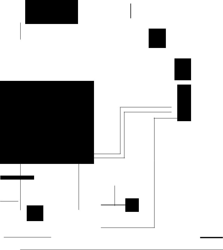
CD-K777X
~- :;, :
TOpCal:lin~t!
'$ideGabiilet
;(Righ.t): .j
-.(Sl.}x2 es xamm "
(B1 )x2
.. ~ J • 03x8\nm ..
.. ,,';i
(DJ) x8 03ksmm;
a~bk Board
(F2 ) x1 ~~~s>i
(J2) ~1
," QSP PWB
(Jf) x4 ea xtnrnrn
Figure ~-2~;
- |
.... |
' •.1 |
I |
:,
Oisplal~WB
.A |
c |
( L'.lx6 |
|
|
a~I~~~~~y~';:},::::::~03l<8riJm |
, |
|||
t |
|
|||
I ';" |
|
Ii (IF1 i'x3 |
||
|
|
|||
|
|
'd3xiomm |
||
|
|
I |
.; |
|
~.;,. oj
(K1-)i -s: 03x10mm
Figure 6·3

Turntable
(N1 ) x2
03 x10mm
Net
( A1 ) x1
Figure 7-4
Figure 7-1
Speaker
Box
Tweeter
CD Servo PWB
Front Panel
(A2) x1
Figure 7-5
Figure 7-2
(Q1 ) x4
03 x12mm
(R1 ) x1
133 x10mm
Shift Lever -74~~~~~~
CD Changer
Mechanism
CD Player Base
Sensor PWB
Gar.ewhen-installingcthecCDchaoger=mecbaoism.-.
Install the CD changer mechanism on the CD player base after the shift lever has been set in the highest position.
CD~K777X
CP~K777
Speaker Box
Woofer
Figure 7-3
-7-
CD-~K777}Q
CP:K777J
REMOVING 'AND~EINSTALLING THE MAIN PA~TS
TAPE MECHANISM SECTION |
|
|
|
Perform steps 1,2,3,4,5, 10anQ11 of the disassembly method |
|
HecordlPlaybaek |
|
to remove the tape mechanism. |
J! :. |
||
Head |
|||
|
|
How tf;> remove therecord,/playback and erase headsi(TAPE 2)rSeeFig;~hi.)
1. Carefully bend the r~cdrcllplay.backhead pawls (At) x 2 pes.,
in the |
direction of the arrow ®; 'andremove the.record/ |
|
playback head upw'ards.;:; .I; / |
'-. -~\: |
|
~ |
- i' I -- .-__' -.• \ |
, . -_ --' .1 |
2. Carefully bend the ,thrre"pawls J~1) x 3 pes.,;II1:thearrow di rection@. and remo)i4;l the~rJljilei head ,upward:' ;
How to remove t~e"piaYlJ.ad~hea~(TAPE1)
(see Fig. a-2~)< |
'-' |
, |
1.CarElfJlly'8eridtheplayback head;pa,wls (<;:1) x 2 pcs., in the direction of the arrow ©, and (remove tHe playback head
upwards.
How to remove the pinbh~f6l1er (TAPE 1/2)
(See Fig. a-3.) |
:J, |
" |
1. Carefully bend the |
|
",1 |
pinch rbrr~!1P9-,\!V.1 in the direction of the |
||
arrow ©, and remove the pineh roller (D1) upwards. |
||
Note: |
|
":,, " |
Wh~n installing the pinch roller, pay"attEintion to the spring rnountlnq method, " "" d' ,
" ..:""
,1 I
,."
'0.1
How to removeltle belt (TAPE~l(~~e Fig. a-4.)
1. Remove the main belt (E1) x 1 pc..'fr6irdhe motor side.
I', . ',".
Howloretnove]he bE!1t (lA'P'E2) (Se-e'Fig.a-4.)
1.Remove the tape t main belt (E1) x 1pc..from the motor side.
2.Removethetapl=lg:maih belt (F1) x 1pc., from the motbrside.
3.Remove the-FFtREW belt (F2) xi pc.
How to remove the}11otodSee Fig. s-s.)
1.Remove the belt.
2.Remove the screws (G1) x2 pes., to remove the motor fixture.
3.Remove the screws (G2) x2 pes, to ~emdveihemotor.
Note: ... , .. ': "
When mounting the motor, paY1;i\temionto the motor mounting angle. ..
Pawl (C1) x2
FlgurEl8-2
Pinch Rhller(D1) xi
• I
Pawl
(G1) x2
02 x4mm |
FigureS-3 |
|
|
Motor |
ITAPE11 |
|
|
I |
,I .. ~Mot" ,~,.
TAPE 2 . |
TAPE 1 |
MaIn Belt |
Main B~il . !,! i |
F1jxf . (E1b<"1, :; 'I: ,
Figure 8·5
Figu'reB-4
-8-

CD-K777X
CP-K777
CD MECHANISM SECTION
Perform steps 1,2,3,15 and 16 of the disassembly method to remove the CD mechanism.
How to remove the loading motor (See Fig. 9-1.)
1.Remove the screws (A1) x 2 pes., to remove the loading motor.
Figure 9-1
How to remove the select motor (See Fig. 9-2.)
1. Remove the screws (B1) x 2 pcs., to remove the select motor.
Select Moter
Figure 9·2
How to remove the pickup (See Fig. 9-3.)
1.Remove the screws (C1) x 2 pcs., to remove the shaft (C2).
2.Remove the stop washer (C3) x 1 pc., to remove the gear (C4).
3.Remove the pickup.
Note:
After removing the Flexible PWB for the optical pickup from the connector wrap the conductive aluminum foil around the front end of Flexible PWB so as to protect the optical pickup from electrostatic damage.
( 81 ) x2
02 x5mm
|
|
CD Mechanism |
_-CC2}xl .. |
__ . __ |
-CQ.;l) xt. |
- - |
(C3) x1 |
|
___________________~~-------------- |
'Eigure..s~--------- |
|
-9-

ADJUSTMENT
MECHANISM SECTION
" |
, • " . \ j |
" - |
|
|
|
.! |
|
|
|
|
|
|
• DrivirigF.()fCE!, C?hec;k |
|
|
|
|
|
|
|
|||||
, "'tor'que'Meter |
|
|
iSpecified VCl-lue |
|||||||||
Play: TW-2412 |
-. |
|
, |
|
Tape 1:Oyer8()g |
i |
||||||
; |
|
|
|
|
||||||||
|
|
, |
|
|
|
|
Tape 2: Over80g |
: |
||||
|
|
|
|
|
|
|
|
|
|
|
|
|
|
|
|
|
|
|
|
|
|
|
|
|
|
|
|
|
|
|
|
|
|
|
|
|
|
: _,I, |
|
|
|
|
|
|
|
|
|
|
|
|
, |
|
|
|
|
|
|
|
|
|
|
|
|
|
,Tor~ue Meter |
I |
|
|
: |
Specified yalue, |
|||||||
|
|
|
|
|
|
|||||||
, |
|
I |
|
|
|
|
|
|
|
|
|
|
|
|
|
|
., |
|
Tape 1, |
, . , |
Tape 2 |
||||
|
" |
<:» |
|
|
|
|
|
|||||
|
|
|
- |
sotc.eo g. cr.rJ·. |
|
30t060 g,.cm T: |
||||||
Play:TIN-2111' '.:: |
|
|
|
|||||||||
|
|
|
|
|
|
|
|
|
|
|
|
|
Fast forward:,TW-223.1 |
|
|
|
|
,.- |
|
60 toJ 20 g.cm |
|||||
Rewind:TW-2231 |
|
|
|
|
|
|
|
~60t0120 g.cm |
||||
|
|
|
|
|
|
- |
..- , |
|
||||
|
|
|
|
|
|
|
|
|
|
|
|
|
|
|
|
|
|
|
|
||||||
|
Test Tape |
|
|
Adjusting |
Specified |
Instrument |
||||||
|
|
|
|
|
|
Point |
|
Value |
Connection |
|||
Normal |
MTT-111 |
|
VRM01; )':~i |
3,000:1:/ |
Speaker |
|||||||
speed |
|
|
|
|
|
|
|
30.Hi |
|
|
terminal |
|
|
|
|
|
|
|
|
|
|
|
|
|
(Load |
|
|
|
|
|
|
|
|
, |
|
|
resistance: |
|
|
|
|
|
|
|
|
|
|
|
|
|
8 ohms) |
|
|
|
|
|
|
|
|
|
|
|
|
|
i:
TAPE MECHANISM PWB
I TAPE MECHANISM I
TUNER SECTIO~;,). |
-;, -~I] |
|
|
|||||
fl;::low~mn!lH?frElql,JenGY,:·: |
|
|
|
|
||||
fH: High-renge frequency |
|
, • |
|
|
||||
• AM IF/RF |
'I |
' -~ |
|
" . ');' |
|
|||
S'Igna generaI or: 400 H30%z, |
AM rnaduaeltd |
' -: :" j |
||||||
.Test_Stage. |
|
Frequency |
Frequency |
~f!ttjl1gl |
Instn.'nf~ntj |
|
||
|
|
|
|
Display |
Adjusting |
Connection |
|
|
|
|
|
|
|
|
Parts |
i,'.,,: |
|
|
|
|
|
|
|
|
|
|
IF |
|
450 kHz |
|
1,602 kHz |
T351 |
*1 |
|
|
Band |
|
- |
|
531 kHz |
(fL): TS04 |
"2 |
|
|
Coverage |
|
|
|
|
|
1.1 ± 0.1 V |
|
|
Tracking |
|
990 kHz |
|
990 kHz |
(fL): T302 |
"1 |
|
|
*1. Input: Antenna, |
Output: TP302 |
|
|
|
||||
*2. Input: Antenna, |
Output: TP301 |
|
|
|
||||
• FM RF
Signal generator: 1 kHz, 75 kHz dev., FM modulated
Test Stage |
Frequency |
Frequency |
|
Settingl |
Instrument |
|
|||
|
|
|
|
Display |
|
Adjusting |
Connection |
|
|
|
|
|
|
|
|
|
Point |
|
|
Band |
|
- |
|
87.50 MHz |
L303(fL): |
*1 |
|
||
Coverage |
|
|
|
1.85V±50mV |
|
|
|||
RF |
" .. |
98.00 MHz |
98.00 MHz |
L302 |
'2 |
|
|||
- ') |
|
|
|
|
|
|
|
|
|
|
I.> |
(10,-39 dB); |
'j,';" •. - |
".' |
)i |
;- |
'j |
|
|
|
|
||||||||
|
|
|
|
|
|
, |
|
,. \, - J; |
|
|
,'co" |
.", |
|
'1~ , \-1 |
, |
|
|
||
*1: Input: 'Antenna, |
Output: TP301 |
|
|
|
|
||||
*2. Input: Antenna, |
Output: Speaker terminal |
|
|
||||||
• Detection
Signal generator: 10.7 MHz, FM sweep generator
Test |
Frequency |
Frequency |
Adjusting |
Instrument |
Stage |
|
Display |
Parts |
Connection |
|
|
|
|
|
IF |
10.7 MHz |
98.00 MHz |
T301(Turn |
Input: Pin 1 of |
|
|
|
the core of |
IC301 |
|
|
|
transformer |
Output: TP302 |
|
|
|
T301 fully |
|
|
|
|
counter- |
|
|
|
|
clookwise.) |
|
|
|
|
|
|
• FM Mute Level
Signal generator: 1kHz, 40 kHz dev., FM modulated
Frequency |
Frequency |
Adjusting |
Instrument |
|
, ._ Disp~ay |
Parts |
Connection |
|
|
|
|
98.00 MH"i' |
|
I |
'fnp'I,lSOS01..... - |
(25dB).L'II) ; |
|
|
Output:Sp~aker |
|
:i. i.' |
I.;,' ",' |
"j 'TerrtiinaJ |
|
|
., |
, |
|
|
|
*1. Adjust so that an output signal appears. |
|||
ITUNER PWS:j'-·j |
'/'. |
|||
|
|
|
|
|
|
.r |
|
|
|
|
|
50301 |
||
|
|
|
||
|
|
|
|
ANTENNA |
|
|
|
|
TERMINAL |
|
|
|
|
|
CNf'301
~ITf'302Ii
Figure 10 ADJUSTMENT POINTS
-10-
CD~K777X
CP~K777
CD TEST MODE
• Setting the test mode
Anyone of 4 test modes can be set by pressing several keys as follows. |
|
|||
<MEMORY> + <CD> + <POWER> |
TEST: CD operation test |
|
||
Setting of TEST mode |
] |
|
|
|
Infication of CD TST mode (See Fig. 11-1) |
Initialize is not |
|
||
OPEN/CLOSE operation is manual operation, |
performed, |
|
||
Thle pickup can be moved by using the (»0-) or (.....) key. |
|
|
||
<MEMORY> |
|
<STOP> |
<MEMORY> |
<STOP> |
When the tracking servo is - |
The pickup returns to the - When the tracking servo is - |
The pickup returns to the |
||
turned on, PLAY is started at |
ordinary stop position. |
turned off, PLAY is started |
ordinary stop position. |
|
once. |
|
|
at once. |
|
t<PLAY> key |
inputTOC. IL is performed, and the ordinary PLAY is performed. - Press <STOP> key. - Stop |
|||
If the following key is pressed during PLAY, it is possible to |
|
|||
specify directly any Track No. <Disc Number 1> key: Track 4 <Disc Number 2> key: Track 9
<Disc Number 3> key: Track 15
Note:
OnIy in STOP state it is possible to slide the pickup with the (»0-) or (.....) key.
VOL. ._- Last memory
BAL, --- CENTER
R.GEQ.._- FLAT
X-BAS --- OFF
Canceling method - POWER OFF
[!]~ 00 ~ !M[gIWl@!ffiW X4iA186 ~
00 [!] l!J 00 |
M1MOOIMl e) l~©l [p'11!iI |
|
a @ |
®~[g[gL9l |
|
~~~~ ~ |
1M |
|
~~~~ |
@) @ |
fjS~ |
oaU 0=0 • D=O fl a~aCa;~=anll
~J!O ~~ o,~ D-.~'~' ~115~ "D-.~'
Figure 11·1
~CD o~ = |
= |
= |
~. |
|||
|
|
.~ |
= |
= |
= |
~o |
IUIlHlI: ~ o~ |
= |
= |
= |
|||
= |
= |
= |
~o |
|||
|
|
|
= |
= |
= |
|
|
|
|
= |
= |
= |
|
|
|
o~ |
= |
= |
== |
~. |
|
C; |
o~ |
= |
= |
= |
~o |
~~ |
|
= |
= |
|||
|
o~ |
= |
= |
= |
~. |
|
|
c- |
= |
= |
= |
|
|
|
|
= |
= |
= |
~. |
|
|
0= |
= |
= |
= |
||
D.~~ |
|
= |
= |
|
||
DO 63 |
250 |
= |
16k |
|||
= |
1k |
4k |
||||
CD SECTION
Since this CD system incorporates the following automatic adjustment function, when the pickup is replaced, it is not necessary to readjust it.
• Automatic adjustment item
1.Focus Dffset (Fig. 11-2)
2.Tracking offset (Fig. 11-3)
3.ElF balance (tracking error balance) (Fig. 11-4)
4.RF level AGC function (HF level: constant)
5.RF level automatic follow-up of the tracking gain
This automatic adjustment is performed each time a disc is changed. Therefore, each disc is played back using the optimal settings.
0.15 |
|
|
|
|
|
|
|
|
|
|
|
|
|
|
10ms |
|
|
|
|
|
|
|
|
|
|
|
|
Enlarged |
|
|
|
|
|
|
|
|
|
|
|
|
|
|
|
|
|
|
|
|
|
|
|
|
|
|
|||
0.50 V |
|
|
|
|
|
|
|
|
|
|
|
|
|
|
|
|
|
|
|
|
|
|
|
|
|
|
VIew |
|
|
|
|
|
|
|
|
|
I |
|
|
|
|
|
0.50 V |
|
|
|
|
|
|
|
|
|
|
|
|
||
IC1@FD |
|
|
|
|
|
|
|
|
|
|
|
|
|
|
|
|
|
|
|
|
|
|
|
|
|
|
||
|
|
|
|
|
|
|
|
|
|
|
|
|
lCl@FD |
|
|
|
|
|
|
|
|
|
|
|
|
|
||
|
|
|
l. |
-V |
|
|
|
|
\ |
|
|
|
|
FOCUS |
|
|
|
|
|
|
|
|
|
|
|
|
|
|
|
|
|
|
|
|
|
|
|
|
|
|
|
|
|
|
|
|
|
|
|
|
|
|
|
||||
|
|
|
|
|
|
|
|
|
|
|
|
|
|
OFF-SET |
|
|
|
|
|
|
|
|
|
|
|
|
|
|
o.rs |
|
|
|
|
|
|
|
|
|
|
r-- |
|
|
ADJUST |
lams |
|
|
|
|
|
|
|
|
|
|
|
|
|
|
|
|
|
|
|
|
|
|
|
|
|
|
|
|
|
|
|
|
|
|
|
|
|
|
|
|
||
|
|
|
|
|
|
|
|
|
|
|
|
|
|
|
|
|
|
|
|
|
|
|
|
|
|
|
||
|
|
|
|
|
|
|
|
|
|
|
|
|
|
|
|
|
|
|
|
|
|
|
|
|
|
|
||
0.50 V |
|
|
|
|
|
|
|
|
|
|
|
|
|
|
0.50 V |
|
|
|
|
|
|
|
|
|
|
|
|
|
IC1@TO |
|
|
|
|
|
|
|
|
|
|
|
|
|
TRACKING |
ICl @)TO |
|
|
|
|
|
|
|
|
|
|
|
|
TRACKING |
|
|
~ |
|
|
|
|
|
|
|
|
|
|
|
|
|
|
|
|
|
|
|
|
|
|
|
|
OFF-SET |
|
|
|
|
|
|
|
|
|
|
|
|
|
|
OFF-SET |
|
|
~ |
./ |
|
|
|
|
|
|
|
|
|
||
|
|
|
|
|
|
|
|
|
|
|
1 |
|
|
|
|
|
|
|
|
|
|
|
|
ADJUST |
||||
|
|
|
|
|
|
|
|
|
|
|
|
ADJUST |
|
|
|
|
|
|
|
|
|
1 |
||||||
|
|
|
|
|
|
|
|
|
|
|
|
2 |
|
|
|
|
|
|
|
|
|
|
|
|
|
|||
|
|
|
|
|
|
|
|
|
|
|
|
|
|
|
|
|
|
|
|
|
|
|
|
2 |
|
|||
|
|
|
|
|
|
|
|
|
|
|
|
|
|
|
|
|
|
|
|
|
|
|
|
|
|
|||
|
|
|
|
|
Figure 11-2 |
|
|
|
|
|
|
|
Figure 11-3 |
|
||||||||||||||
200 ms |
|
|
|
|
|
|
|
|
|
TRACKINGI |
|
|
|
|
|
|
|
|
|
|
|
|
|
|
||||
1V/diV |
|
|
|
|
|
|
|
|
|
ERROR |
|
|
|
|
|
|
|
|
|
|
|
|
|
|
||||
ICl @ |
|
|
|
|
|
|
|
|
|
BARANCE |
|
|
|
|
|
|
|
|
|
|
|
|
|
|
||||
TO |
|
|
|
|
|
|
|
1ADJUST |
|
|
|
|
|
|
|
|
|
|
|
|
|
|
||||||
|
|
|
|
|
|
|
|
|
|
|
|
|
|
|
|
|
|
|
|
|
|
|
|
|||||
200 rns |
|
|
|
|
|
|
|
|
|
|
|
|
|
|
|
|
|
|
|
|
|
|
|
|
||||
1V/diV |
|
|
|
|
|
|
|
|
|
|
|
|
|
|
|
|
|
|
|
|
|
|
|
|
||||
IC10 |
|
|
|
|
|
|
|
2 |
|
|
|
|
|
|
|
|
|
|
|
|
|
|
|
|||||
TE 0 |
|
|
|
|
|
|
|
|
|
|
|
|
|
|
|
|
|
|
|
|
|
|
||||||
Ice0-sERve-PWB-1
Figure 11-4
Figure 11-5 CHECKING POINTS
-11 -

~--' -.
~ _"Js • ,J |
l ~ _ ) |
'.'f;:"· |
|
'.,'} |
|
PICKUP UNIT
: -- -------- |
-------- |
,7,-- ------ ;,-\~~';_:_ |
-------1 |
|
|
||||||
: |
J ; j -. I! |
|
|
.lI;. |
,- - -,~' , |
"l':' L';: ~': .: |
|||||
: |
r: ',':,';,I ~,: |
,,11 ,:' |
, ..,.,':1:,. |
|
|
||||||
I |
|
|
|
|
|
|
I |
||||
I |
|
|
|
|
|
|
I |
||||
: |
P |
';'. |
|
|
|
: |
|
|
|||
:I |
|
" |
|
|
|
|
|
: |
|
|
|
|
|
|
|||||||||
|
|
||||||||||
|
|
|
|
|
|
|
|
|
|
|
|
|
|
|
|
|
|
|
I |
|
|
||
|
|
|
|
|
|
|
I |
|
|
||
|
|
|
|
|
|
|
I |
|
|
||
|
|
|
|
|
|
|
I |
|
|
||
|
|
|
|
|
|
|
I |
|
|
||
|
|
|
|
|
|
|
I |
|
|
||
|
|
|
|
|
|
|
I |
|
|
||
|
|
|
|
|
|
|
I |
|
|
||
|
|
|
|
|
|
|
I |
|
|
||
|
|
|
|
|
|
|
I |
|
|
||
|
|
|
|
|
|
|
I |
|
|
||
|
|
|
|
|
|
|
I |
|
|
||
|
|
|
|
|
|
|
, |
|
|
||
|
|
|
|
|
|
|
I |
|
|
||
|
|
|
|
|
|
|
, |
|
|
||
|
|
|
|
|
|
|
, |
|
|
||
|
FOCUS COIL |
|
-,,;i l-,~ |
|
|
||||||
|
|
|
|||||||||
|
~~----';-'-"'---~"'" |
|
|
||||||||
|
|
|
|
|
|
|
|
|
|
|
|
|
|
|
|
|
|
J; ~ I |
|
|
|
|
|
|
|
|
|
|
|
|
|
LASERi': |
|
|
|
|
|
|
,I POWEF(":' |
~' |
|
|
'bONT.ROi?;: |
|||
: |
|
|
|
.', 'I ~ ,'.' L: --ii;-;'~',';: -:\!~£J~: |
||
'--~--:-__::M;)------''''~-~;:·7i-;;i)'~~~~;~;-----_: |
||||||
|
:'sLioE,l';'",; |
, "iS~IN ,", |
||||
|
MQTOR |
MOTOR |
||||
.>, |
.. "IUr:nq |
. '.~.' ~ \ .
F,O J
~J ~ L;'
1-"(1; >;J:~1
,.,q -;1 1,
:;:. ~ : i jl \"/~.;
IC1
LA9231M
SERVdAM'P.
.-,J -"-JJ ".- .,:1,;::'.,'j ~j ,
; -;L;'-. _,-.:~ _ ,:. :'_) " . - '! .. i
CL,DAT,SELIAL CONTRI
-" -',.',c" ; i .. ·
SL+.SL-.DRF
"
ICS
BA6396FP
;,!',:'\,l'j
DRIVER
-,,:-.,
: J.
PICKUP IN
SW4
PU-IN SW
-'.!.
r ,
rigure 12 BLOCK DIAGRAM (1/6) |
j I ) ,~" • |
-,12-
-------,> XIN XOUT
IC2
LC78620E
SERVO/SIGNAL
CONTROL
r,SELIAL CONTROL
IC4
-+5V IX0039AW
CD CONTROL
MAICON
n
XL2
4.19MHz
CD-K777X
CP~K777
+5V ~+7.3V
8
49~3~~~6 |
NJM4565D |
|
OUT |
||
|
|
IC3 |
AUDL;D |
||
|
|
|
|||
48 |
5 |
OPE AMP. |
|
|
|
|
|
|
|||
|
|
|
|
|
|
|
|
4 |
|
+5V |
|
|
|
(D-QUT) |
|
||
|
|
|
|
|
|
|
|
|
|
|
|
|
|
|
|
|
|
COM,DATA,SCK
TO MAIN MICON
0;4 --------- |
, |
REGULATOR
+7.3V
+5V
+7.3V
GND
+5V
DOUT
L-CH
GND
R-CH
COM
DATA
SCK +7.3V(+B9)
CNP?
Figure 13 BLOCK DIAGRAM (216)
-13-

FMANT
; I
I.
CD MUTE
~ \ \ I
I . J.,
I FROMCDUNITI c---------~---+~--...L.-------+__1f_....=!~f.t_i
TAPEMOTOR i
SWITCHING
RUNPLS
T1 Cr02
12 Cr02
FULLPROQF ooa
TI PLAY STOP
SOLENOID
MECHASTOP
~~
ITAPE,I ~1\\-
r----
I
I
I
I
I
I
I
I
I
r.. •
J601
MIC1
~Eig!Jre.t4:BlQCK;DIAGBAM;{3L6)
-1:4-
REMOTE IN
|
|
SPE:-1 |
|
|
|
SP~-2 |
|
|
|
SPE·~ |
|
I I |
SPE-4 |
|
|
|
|
S'P-5 |
|
|
|
T1PLAY |
|
|
|
T2 RUN |
|
|
|
C,02 |
|
|
|
BIAS |
|
|
|
|
|
|
|
TIm |
|
|
|
PBMUTE |
|
|
|
|
|
|
|
|
|
HIGHSPEED
I04D1
LC75394E
AUDIOPROCESSOR
GRAPHIC EQUALIZER
~
VIDEO
J4C2:
ICS01
M658~5FP
MICAMP.

|
|
|
|
|
|
|
|
|
|
|
|
|
|
|
|
|
|
|
|
CD-K777X |
|
|
|
|
|
|
|
|
|
|
|
|
|
|
|
|
|
|
|
|
CP-K777 |
|
|
|
|
13 |
|
|
|
|
' |
|
|
|
|
|
|
|
|
|
Flm- |
vr |
|
|
|
|
|
FL702 |
|
|
|
|
|
|
|
|
FL 701 |
|
|
"' |
(AC) |
||
|
|
|
|
|
|
|
|
|
|
|
|
|
FL DIPLAY |
|
|
|||||
|
|
|
|
|
~-®W-~. |
|
|
|
|
|
|
|
|
|
||||||
|
|
|
|
|
|
DSPDIPLAY |
|
|
|
|
|
|
|
|
|
|
||||
|
|
|
|
|
|
|
|
|
|
|
|
|
|
|
|
|
|
|
F2f&'"" |
(AC) |
|
|
|
|
|
I |
|
|
|
|
|
|
|
|
y~-, |
|
'" |
||||
|
|
|
|
|
|
|
|
|
|
|
|
|
|
|
||||||
|
|
|
|
|
~ |
|
|
|
|
|
~~UT 5 |
IC701 |
" |
c::::> |
KEYMATRIX |
|||||
|
|
|
|
|
|
|
|
|
VFIP |
|
|
|
|
|||||||
|
|
|
|
|
|
IC702 |
|
|
|
|
|
|
|
|
6 |
j.lPD16311 |
|
KEYOUT |
® SW701_SW710 |
|
|
|
|
|
|
|
~PD6700 |
~, '" |
|
|
|
|
cue |
|
|||||||
|
|
|
|
|
|
FLDRIVER |
|
|
|
|
|
FLDRIVER & |
~~ |
SW7'2-SW733 |
||||||
|
|
|
|
|
|
|
|
|
|
sre |
• |
CONTROLLER E~J |
|
|
||||||
|
|
|
|
|
|
o |
0 |
|
|
|
|
|
|
|||||||
|
|
|
|
|
|
Z |
0 |
, |
sra |
|
|
|
|
|
VSS VDDVEE' |
KEVIN |
|
|||
|
|
|
|
|
|
o |
> |
|
|
|
|
|
|
~rI~LED,101 +85 L -- VP |
|
|||||
TUNER MUTE |
|
|
~iII~LE~706 +B5 |
|
|
|
|
|
|
|
||||||||||
|
|
|
|
|
|
|
|
|
|
|
|
|
|
|
LE070S |
|
|
|
|
|
|
|
|
|
|
LED709 |
|
|
|
|
+610 |
|
|
|
|
|
|
|
+8,0 |
||
|
|
|
|
|
|
|
|
|
|
|
|
|
|
|
|
|
|
|||
,IN |
|
|
|
|
|
|
|
|
|
|
|
|
|
|
|
|
|
|
|
TO OSPUNIT I |
|
|
|
|
|
1ti~U~ll~ffi iii,"'[l: OJ |
|
|
|
|
|
|
I |
|
|
|
|
|
|
TO osp UNIT |
|
|
|
, |
|
|
e |
CD·elK |
|
|
|
|
|
|
|
|
|
|
TOCD UNIT |
|||
|
|
|
|
|
|
|
9 |
CO-GOM |
|
|
|
|
|
|
|
|
|
|
|
|
SPE·, |
t |
|
|
|
|
|
, CD·DATA |
|
|
|
|
,w |
|
|
|
|
|
|
|
|
SPE·2 |
|
|
|
|
|
|
|
|
|
|
|
|
|
|
|
|
||||
e |
|
|
|
|
|
|
|
+84 (BV BACK UP) |
|
UNSWITCH |
|
|
|
|
|
|
|
|||
|
|
|
|
|
|
|
", |
|
|
'" |
|
|
|
|
|
|
|
|
||
SPE-:l |
a |
|
|
|
|
|
|
|
|
|
|
,~ |
|
|
|
|
|
|
|
|
SPE-4 |
, |
|
|
|
|
|
~ +j RESET |
|
|
|
|
|
|
|
|
|
|
|||
SPE-5 |
|
|
|
|
|
|
|
|
|
|
|
|
|
|
|
|
||||
T1 PLAY |
, |
|
|
10751 |
|
|
G~:w"}t~'''"' |
|
|
,w~ |
|
|||||||||
T2RUN |
|
|
M3B127M5 |
|
,"''''''~~ |
ozas |
|
|
|
|
||||||||||
, |
• |
|
|
MICROCOMPUTER |
|
|
RESET |
BACKUP |
|
CD LD HIL 060, |
OBoe |
|
|
|
||||||
o~, |
|
|
|
|
|
|
XL751 |
|
|
|
|
|
|
|
|
|
|
|
|
|
BIAS |
|
|
|
|
|
1 |
419MHz |
|
|
|
|
|
|
|
|
|
e |
|
||
|
|
|
|
|
~:KOSC |
|
|
|
|
COLD M+ |
|
|
|
M |
||||||
T,1T2 |
|
|
|
|
|
|
|
|
|
|
t |
|
IC801 |
|
||||||
|
|
|
|
|
|
|
XL752 |
|
|
|
|
CDLOM |
|
|
|
|
||||
'" |
|
|
|
|
|
|
52.7B8KHz |
|
|
|
|
a |
|
iID-J |
|
|||||
PB MUTE |
|
|
|
|
|
|
|
|
|
," |
|
|
|
|
|
LOADING MOTOR |
||||
~ , |
, |
, , |
, |
, |
|
|
|
I |
Z07S1 |
|
|
DRIVER |
|
|
|
|
||||
|
|
|
|
|
|
|
|
SYSTEM STOP |
I |
om |
|
|
|
LOADING MOTOR _ ~ |
|
|
||||
|
|
|
|
|
|
|
|
|
|
|
0753 |
|
|
|
|
|
|
|
|
|
|
§~QQ5e~g~~ ~ffiS:jd:i!~ |
P" |
|
|
|
|
P.FAIL DET |
|
|
|
|
INVERTER |
|
DRIVER |
|
|||||
|
|
|
|
|
|
00 |
|
|
|
|
|
|
|
|
|
|
|
|
|
|
|
|
|
|
~15!l!999Q |
|
|
|
|
|
|
|
|
|
COM |
|
ceca |
|
|||
|
|
|
|
l::t;jo |
|
|
|
|
|
|
|
CDTfT+M |
ce» |
M |
||||||
|
§~~~~§888"- "- |
cCc,,- |
:; l:: P |
|
|
|
|
|
|
|
|
|
|
|
|
|||||
|
5l |
~ |
0 |
|
ooo~ |
0:; c |
|
|
|
|
|
|
~ |
|
|
|
|
|
|
TfTMOTOR |
|
w< |
|
|
8 |
00 |
|
|
|
|
|
|
|
|
|
|
|
|
|
||
|
~ |
l-' |
|
|
|
|
|
|
|
|
|
|
~ |
CD TfT STOP |
|
oe04 |
|
|
||
|
|
|
|
|
|
|
|
|
|
|
|
|
|
|
|
|
|
|
||
|
|
|
|
|
|
|
|
|
|
|
|
|
|
CD TfT OPENICLOSE |
|
|
I |
~~~~;E |
||
|
|
|
|
|
|
|
|
|
|
|
|
|
|
|
|
|
|
|
||
|
|
|
|
|
|
|
|
~ |
~ |
|
|
|
|
DISC NO |
|
|
|
|
~DISCNO |
|
|
|
|
|
|
|
|
|
~ |
~ |
|
|
|
|
|
|
|
|
|
|
|
|
|
|
|
|
|
|
|
|
|
|
|
COUPIDOWN |
|
|
|
|
||||
|
|
|
|
|
|
|
|
|
|
POWER ON/STB |
|
|
|
|
|
|
||||
~ |
ago, |
esse |
|
|
RELAY |
|
|
|
~ MEHCAUP |
|
|
|
|
|
|
||||
OS02 |
|
|
|
|
|
|
|||
|
|
|
|
|
|
|
|
||
|
|
SWITCHING |
|
PROT |
|
|
|
||
|
IC902 |
|
|
|
|
|
|
|
|
|
NJM4585D |
|
|
|
|
|
|
|
|
|
OPE AMP |
|
|
|
|
|
|
|
|
JR |
|
|
|
|
OC, |
|
|
" |
|
|
|
|
." |
|
|
|
|
|
|
C""'~ |
|
|
~¥ |
|
|
as' |
, |
|
|
|
||||||||||||||||||||
|
|
|
|
|
|
|
|
|
, |
|
|
, |
6 |
~~~T |
|
|
|
|
|
|
|
|
|
|
|
|
|
|
|
|
|
|
|
|
, |
|
|
|
||||||||||||
|
|
~ |
c |
|
|
" |
|
|
|
|
|
|
|
|
|
|
|
|
|
|
|
|
|
|
|
|
|
|
|
|||||||||||||||||||||
|
|
|
|
|
|
|
|
|
|
|
|
|
|
|
|
|
|
|
|
|
|
|
|
|
|
|
|
|
|
|
|
|
|
|
|
|
|
|||||||||||||
|
|
|
|
|
-"" |
|
|
|
|
|
R-IN |
'IC801 |
|
|
;,;,OUT |
|
|
|
|
|
|
|
|
|
|
|
|
|
||||||||||||||||||||||
, |
0"', |
|
|
'"0 |
|
"'g |
|
|
|
|
|
|
|
|
|
|
, |
|
|
|
,~ |
|
|
|
|
|
|
,- J |
RL901 |
|
|
5]J601 |
||||||||||||||||||
|
|
|
|
|
|
|
|
|
|
|
|
|
|
|
|
|
|
|
|
|
|
STK4152M |
|
|
1 |
|
|
|
|
|
|
|
|
|
|
|
|
|
|
|||||||||||
|
|
|
un |
|
|
|
|
|
|
|
|
-" |
|
|
|
VOLTAGE |
|
If;' |
|
|
|
|
|
|
|
|
L |
|
~ |
RELAY |
|
|
|
|
|
|
|
|||||||||||||
|
|
|
|
|
|
|
|
|
|
|
|
|
|
• |
|
|
|
|
|
|
|
|
|
|
POWE~1lo", |
|
|
|
, |
|
-,, |
|
|
|
|
|
|
|
|
HEADPHONES |
||||||||||
|
|
|
|
|
|
AV•• |
|
|
|
|
|
|
|
|
|
|
|
|
|
|
|
|
|
|
|
|
|
|
|
|
|
|
|
|
|
|
|
|
|
|
|
'" |
|
|
|
|||||
|
|
|
|
|
|
|
|
|
|
|
|
|
|
|
|
|
|
|
|
|
|
|
|
|
|
|
|
|
|
|
|
|
|
|
|
|
|
|
|
|
|
|
|
|||||||
|
|
j' |
|
|
|
|
|
|
|
|
|
|
|
|
|
|
REGURATER |
|
|
|
|
|
|
|
|
|
|
|
|
|
|
|
|
|
|
|
|
|
|
|
|
L-CH |
||||||||
|
|
|
|
|
|
|
|
|
|
|
|
|
|
|
|
|
|
|
|
|
|
|
|
|
|
|
|
|
|
|
|
|
|
|
|
|
|
|
|
|||||||||||
|
|
|
|
|
|
|
|
|
|
|
|
|
-" |
|
~'8V |
~ |
|
|
|
|
|
|
|
|
|
|
|
|
|
|
|
|
|
|
|
|
|
|
|
|
|
|
|
|
SOSO, |
|||||
|
|
|
|
|
|
|
|
|
|
|
|
|
|
|
|
|
|
|
|
|
|
|
|
|
|
|
|
|
r: |
|
|
|
|
|
|
|
|
|
|
|
|
|
|
|
.ffG[o |
'"' |
||||
|
|
|
|
|
|
|
|
|
|
|
|
|
|
|
|
|
|
|
|
|
|
|
|
|
|
|
|
|
|
|
|
|
~ROTECTION |
|
|
|
|
|
|
|
|
|
|
|
|
|
|
SPEAKER |
||
|
|
|
|
|
|
|
|
|
|
|
|
|
|
|
|
|
|
|
|
|
|
|
|
|
|
|
|
|
|
|
|
|
|
|
|
|
|
|
|
|
|
|
|
|
|
|
TERMINAL |
|||
|
|
|
|
|
|
." |
|
|
|
|
|
|
|
|
|
|
|
VOLTAGE |
|
|
|
|
|
|
|
|
|
|
|
|
|
|
|
|
|
|
|
|
|
|
|
|
|
|
'"' |
|||||
|
|
|
|
|
|
|
|
|
|
|
|
|
|
|
|
|
|
|
|
|
|
|
|
0850 |
|
|
0682 |
|
|
1 |
|
|
|
|
|
|
|
|
|
~ |
||||||||||
|
|
|
|
|
|
|
|
|
|
|
|
|
|
|
|
|
|
REGULATOR |
|
|
|
|
|
|
SWITCHING |
|
|
|
|
|
POWERresr |
|
|
|
"'" |
|
||||||||||||||
|
|
|
|
|
|
|
|
|
|
|
|
|
|
|
|
|
|
|
|
|
|
|
|
|
|
|
|
|
|
|||||||||||||||||||||
|
|
|
|
|
|
|
|
|
|
|
|
|
.~ |
|
|
|
|
aa~, |
|
|
|
|
|
|
|
|
|
|
|
|
|
|
|
|
|
|
|
|
||||||||||||
|
|
|
|
|
|
|
|
|
|
|
|
|
|
+5VUN-SWITCHED |
|
|
|
|
|
|
|
|
|
|
|
|
|
|
|
|
TRANSFORMER |
|
|
|
||||||||||||||||
|
|
|
|
|
|
|
|
|
|
|
|
|
|
|
|
|
|
|
|
|
|
|
|
|
|
|
." |
|
|
|
|
|
|
|
|
|
F654 J::- - - - - - - -, 2~0-24OV |
|||||||||||||
|
|
|
|
|
|
|
|
|
|
|
|
|
|
|
|
|
|
|
|
|
|
|
|
|
|
|
|
|
|
|
|
|
|
|
|
|||||||||||||||
|
|
|
|
|
|
|
|
|
|
|
|
|
|
|
|
|
|
VOLTAGE |
|
~1V) |
|
|
|
|
|
|
|
|
|
T4A |
I S |
|
|
|
|
|
|
|
|
SW651 |
||||||||||
|
|
|
|
|
|
|
|
|
|
|
|
|
|
|
|
|
|
1--" |
|
|
1(+~1V) |
|
|
|
|
|
|
|
|
|
|
|
|
|
|
|
|
|||||||||||||
|
|
|
|
|
|
|
|
|
|
|
|
|
|
|
|
|
|
REGULATOR |
|
|
|
|
|
|
0651 |
K |
|
|
|
|
Ll!50V |
I |
|
|
|
|
|
|
|
1220V K |
VOLTAGE |
|||||||||
|
|
|
|
|
|
|
|
|
|
|
|
|
." |
|
|
|
|
|
|
|
|
|
|
|
|
|
|
|
|
|
|
|
|
|
|
|
|
|
|
|
SELECTOR |
|||||||||
|
|
|
|
|
|
|
|
|
|
|
|
|
|
+5~N_SWITCHED |
|
|
|
|
|
|
|
|
|
|
|
|
|
|
|
|
|
|
|
|
|
|
|
|
|
|
||||||||||
|
|
|
|
|
|
|
|
|
|
|
|
|
|
|
|
|
|
|
|
|
|
|
|
|
|
|
|
|
|
|
|
|
|
|
|
|
|
|
|
|
|
|
||||||||
|
|
|
|
|
|
|
|
|
|
|
|
|
|
0640 |
|
|
|
|
|
|
|
|
|
|
|
|
|
|
|
F6:siti |
|
|
|
|
|
1127V 'f |
||||||||||||||
|
|
|
|
|
|
|
|
|
|
|
|
|
|
|
|
|
|
|
|
|
|
|
|
|
|
|
|
|
|
|
|
|
|
|
|
|
|
|
|
|
|
|||||||||
|
|
|
|
|
|
|
|
|
|
|
|
|
|
|
|
|
|
|
|
|
|
|
|
|
|
|
|
|
|
|
|
|
|
|
|
|
|
, |
|
|
|
|
|
, |
|
|
|
F6B6 |
||
|
|
|
|
|
|
|
|
|
|
|
|
|
|
|
|
|
|
VOLTAGE |
----0 |
|
|
|
|
|
|
|
'" |
, |
|
|
|
|
|
|
|
rttov |
"" |
|||||||||||||
|
|
|
|
|
|
|
|
|
|
|
|
|
|
|
|
|
|
REGULATOR |
|
|
|
|
|
|
|
|
Ll!50V |
|
|
|
|
|
, |
|
|
|
l250V |
|||||||||||||
|
|
|
|
|
|
I |
|
|
i |
|
." |
|
|
VOLTAGE |
|
|
|
|
|
|
|
|
|
|
|
|
tasov |
, |
|
|
|
|
|
|
|
|
- |
|||||||||||||
|
|
|
|
|
|
|
|
|
|
|
|
|
|
|
|
|
|
|
|
|
|
|
|
|
|
|
|
|
|
|
|
|
|
|
|
, |
|
|
|
|||||||||||
|
|
|
|
|
|
TO asp UNIT |
|
|
|
|
|
|
+12V MOTOR\ |
OB~2 |
|
|
|
|
|
|
|
|
|
|
|
|
|
|
|
|
|
|
|
|
|
, |
|
|
|
|||||||||||
|
|
|
|
|
|
|
|
|
|
|
|
|
|
|
|
|
REGULATOR |
|
|
|
|
|
|
|
|
|
|
|
|
|
|
|
|
|
|
|
|
|
, |
|
|
|
||||||||
|
|
|
|
|
|
|
|
|
|
|
|
|
|
|
|
|
|
|
|
|
|
|
|
|
|
|
|
|
|
|
|
"m,,~ |
"" |
, |
|
|
|
|
|
|
|
|
|
|
|
AC 11011271 |
||||
|
|
l, |
|
|
|
|
|
|
B7 |
|
." |
|
|
|
|
CO~ |
|
|
|
|
|
|
|
|
|
|
|
|
|
|
|
|
|
, |
|
|
|
|
|
, |
|
|
|
|
||||||
|
|
|
|
r-e-+ |
|
|
|
|
|
|
+12VIANALOG) |
06~~ |
|
|
|
|
|
|
|
|
|
|
|
|
|
|
|
~ |
|
|
|
, |
|
|
~ |
|||||||||||||||
|
|
|
|
|
|
|
|
.,,-ib_ |
|
|
|
|
|
|
|
|
|
|
|
|
|
|
|
|
|
|
|
|
|
|
|
|
|
, |
|
|
|
AC POWER |
||||||||||||
|
|
|
|
|
|
|
|
|
|
|
|
|
|
|
|
|
|
|
|
|
|
|
|
|
|
|
L _______ -1 |
|
|
SUPPLY COR |
||||||||||||||||||||
|
|
|
|
|
|
|
|
|
|
|
|
|
|
|
|
|
|
|
|
OB52-0684 |
|
|
|
|
|
|
|
|
|
, |
|
|
|
|
|
, |
|
|
|
|
||||||||||
|
|
|
|
|
|
|
|
|
|
|
|
|
|
|
|
|
|
|
|
|
|
|
|
|
|
|
REGULATOR OBs, |
|
|
|
|
|
|
|
, |
|
|
2201230_240 |
||||||||||||
|
|
|
|
|
|
|
|
|
|
|
|
|
|
|
|
|
|
|
|
|
|
|
|
|
|
|
|
|
|
|
|
|
|
|
|
|
T g |
|
|
|
, |
|
|
|
50160Hz |
|||||
VR50~ |
|
|
|
|
|
|
|
|
|
|
|
|
|
|
|
OB35 |
|
|
|
|
|
|
|
|
|
|
|
|
|
|
|
|
T.F I |
|
|
|
||||||||||||||
|
|
|
|
|
|
|
|
|
|
|
|
VOLTAGE SWITCHING |
|
|
|
|
|
|
|
|
|
|
lAC)'"J,IACI |
|
|
|
|
|
|
|
|
|
|
|
|
|
|
|
||||||||||||
|
|
|
|
|
|
|
|
|
|
|
|
|
|
|
|
REGURATER |
|
|
|
|
|
|
|
|
|
|
|
|
|
|
|
|
|
|
|
|
|
|
|
|
|
|
|
|
|
|||||
|
|
|
|
|
|
|
|
|
|
|
|
|
|
|
|
|
|
VOLTAGE |
|
|
|
|
|
|
|
'" |
|
|
|
|
|
|
|
|
|
|
|
|
|
|
|
|
||||||||
|
|
|
|
|
|
|
|
|
|
|
|
|
|
|
|
|
|
REGULATOR |
|
|
|
|
|
|
|
|
|
|
|
|
|
|
|
|
|
|
|
|
|
|
|
|||||||||
|
|
|
|
|
|
|
|
|
ITO CO UNIT I +89 |
|
+7.3V(CD) |
|
OB37 |
|
|
|
|
|
|
|
TO asp UNIT |
|
|
|
|
|
|
|
|
|
|
|
|
|
|
|
|
|||||||||||||
ECHO VOL |
|
|
|
|
|
|
|
|
|
|
|
|
|
|
|
|
|
|
|
|
|
|
|
|
|
|
|
|
|
|
|
|
||||||||||||||||||
|
|
|
|
|
|
|
|
QB3B |
|
|
|
|
|
|
|
|
|
|
|
|
|
|
|
|
|
|
|
|
|
|
|
|
|
|||||||||||||||||
|
|
|
|
|
|
|
|
|
|
|
|
|
|
|
|
|
|
|
|
|
|
|
|
|
|
|
|
|
|
|
|
|
|
|
|
|
|
|
|
|
|
|
|
|
|
|
||||
0639
SWITCHING
Figure 15 BLOCK DIAGRAM (4/6)
-15 -
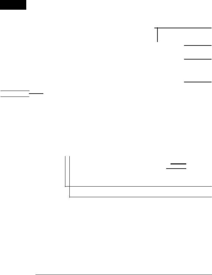
FROM MAINUN~T
n:j~":":":'':''''- |
- +~11 |
i" .
+B12
+811', .
AOUTR+
AOUTR,..
FigiJte1.6.BLOCK'DIAGRAMJ(5,/6)
-16-
CD~K777X
CP~K777
L
)--"=...c:....:.-....-w.-........_ ... +811
AOC INPUT
BUFFER
|
|
|
|
|
|
|
|
|
IC20B |
|
|
|
|
|
|
|
|
|
|
|
|
|
|
|
|
|
|
|
|
C206 |
|
L |
|
|
R |
NJM2115D |
|
|
|
|
|
|||
IM2115D |
|
|
|
|
|
AMP |
|
|
|
|
|
|||
|
|
|
|
|
|
|
|
|
|
|||||
|
|
|
|
|
|
|
|
|
|
|
||||
|
|
|
|
|
|
|
|
|
|
IN |
|
|
|
|
|
|
|
|
|
|
|
|
|
|
|
|
|
|
|
+811 |
VOO |
|
L |
|
|
|
|
|
||||||
14 |
|
|
|
R |
OUT '-- |
-- |
' |
|||||||
|
|
|
|
|
|
|
|
|
||||||
|
|
|
|
|
|
|
|
|
|
|
|
|
|
|
: INPUT JFFER
OSP PASS |
|
SWITCHING |
MUTE |
|
VOLTAGE
REGULATOR
+811 |
--------1 10209 |
|
|
+810 |
TO MAIN UNIT |
|
|||
|
|
|
|
|
|
||||
|
|
|
|
|
VOLTAGE |
||||
|
|
|
|
|
REGULATOR |
||||
+812 |
__----- 1 |
|
|
|
|
AC |
|
|
|
|
|
|
|
||||||
|
|
0281-0284 |
|
|
|||||
|
|
|
|
|
|
|
|||
|
|
SWITCHING |
SWITCHING |
||||||
|
|
||||||||
Figure 17 BLOCK DIAGRAM (6/6)
-17-

A
B
PICKUP UNIT(S06)
I j
c
Fl:).1;-J |
A\,,_' |
, |
|
|
"---~"---, |
, |
,---'===',===============--"/ |
||
) I |
I |
I |
I |
IDSP PWB-E I |
I |
I CNS'S02 I |
I CNS2!J;! I |
I CNS'203 I |
|
I |
||||
CNS!!51 |
TO MAINFW8 |
TO MIG PW8 |
TO MAIN?W8 |
|
|
|
|||
|
P27 Sl·G |
P2El |
P27 B·B |
|
D
J
I
I
L ...i._.~"': _
,
" ,
r ---
E
1 |
|
1 |
_ |
L |
F
J
I
"a , ---
II"
G
"'1'POWl:R PWB·CI
|
AC POWERSUPPLYCORD |
H |
ACnOnV~:JG-24OV |
5W6~H:r |
The numbers 0 to 6 are waveform numbers shown in page 41.
1 |
2 |
3 |
4 |
5 |
6 |
Fig~'r~)1~':'WIl~ING6F'~:W.BdA·R6·(1/6)
-18-

CD~K777X
CP-K777
ICD SERVO PWB-F1 I
000 |
o |
|
CNS2B |
WH |
CNS2A |
||
|
|
s |
|
6 |
|
|
|
|
H |
||
|
|
, |
|
4 |
|
-------- |
|
5 |
|
|
6 |
|
, |
|
GY |
2 |
|
|
|
3 |
|
H |
a |
|
|
1 |
|
D |
1 |
|
|
I CD MOTOR PWB-J I |
|
|
|
• |
|
||||
|
|
|
|
|
|
|
|
||||
|
|
|
|
|
|
CNSM |
|
||||
|
|
|
|
|
, , |
|
|
||||
|
|
|
|
|
\ |
|
|
|
|
|
|
|
|
|
|
|
|
|
|
|
|
|
|
|
|
|
|
|
\ |
Ml |
|
|
|
COLORTABLt:. |
|
|
|
|
|
|
I |
|
|
|
|||
|
|
|
|
|
I |
SPIN MOTOR |
|
|
|
BA |
8ROWN |
|
|
|
|
|
|
|
|
|
|||
|
|
|
|
|
I |
|
|
|
|
~DI~I |
~ED |
|
|
|
|
|
, f |
|
|
|
|
||
|
|
|
|
|
|
|
|
|
0_ |
ORANGE |
|
|
|
|
|
|
|
|
|
|
|
YL |
YELLOW |
M2 |
|
|
|
|
|
|
|
|
GA |
BREEN |
|
SLIDEMOTOR |
|
|
|
|
|
|
|
BL |
BLUE |
||
|
|
|
, |
|
|
|
|
|
|
VL |
VjOl.ET |
|
|
|
|
|
|
|
|
|
|||
|
|
|
|
|
|
|
|
|
GY |
GRAY |
|
|
|
|
\ |
|
|
|
|
|
|
WHIWi |
WHITE |
|
|
|
\ |
|
|
|
|
|
|
||
|
|
|
I |
|
|
|
|
|
|
BK |
SLACK |
|
|
|
|
|
|
|
|
|
|||
|
|
|
I |
|
|
|
|
|
|
PK |
PINK |
|
, , |
G/ |
|
|
|
|
|
|
|||
|
|
|
|
|
|
|
|
|
|||
|
... _-- / |
CNP3A |
|
|
|
|
|
|
|
|
|
|
|
|
, |
|
|
|
|
|
|
|
|
|
|
|
~ |
|
|
|
|
|
|
|
|
|
'-_,----l- |
I |
|
|
|
|
|
|
|
|
|
|
I |
|
|
|
|
|
|
|
|
||
|
|
|
I |
|
|
|
|
|
|
|
|
|
|
|
I |
|
|
|
_ |
|
|
|
|
|
|
|
L |
~~~ |
|
|
|
|
|
||
Figure 19 WIRING OF P.W.BOARD (216)
-19-
A |
|
|
|
|
|
|
|
|
|
|
|
|
|
|
|
|
|
|
|
|
|
|
|
|
fCDSERVOPWB~F1]---------------------------- |
||||||||||||||||||||
|
, |
|
|
|
|
|
|
|
|
|
|
|
|
|
|
|
|
|
|
|
||
|
|
I |
|
'K |
- -- |
- - -- - '". |
|
|
|
|
|
+B |
||||||||||
|
|
|
i''-/':l-! i\/. |
-iF"1f-,~--;===;=+==;=;=:;::::=t==========1====== |
||||||||||||||||||
|
|
|
|
|
|
Rl |
||||||||||||||||
|
[ -0 |
|
|
|
|
|
|
|
|
|
|
|
|
|
|
|
|
|
|
|
||
|
|
|
|
|
|
|
|
|
|
|
|
|
|
|
|
|
|
|
|
|||
|
|
|
|
|
|
|
|
|
|
|
|
|
|
|
|
|
|
|
|
|||
|
"" |
|
|
|
|
|
|
|
|
|
|
|
|
|
|
|
|
|
|
|||
|
|
I |
|
|
|
|
|
|
|
|
|
|
|
|
|
|
|
|
|
|
||
B |
|
II |
|
|
|
|
|
|
|
|
|
|
|
|
|
|
|
|
esc |
|
||
|
|
|
|
|
|
|
|
|
|
|
|
|
|
|
|
|
||||||
|
|
|
|
|
|
|
|
|
|
|
|
|
|
|
|
|
||||||
|
|
,I |
|
|
|
|
|
|
|
|
|
|
0,1 |
|
||||||||
|
A |
|
|
|
|
|
|
|
|
|
|
|
|
|
|
|
|
|
|
|||
|
|
|
|
|
|
|
|
|
|
|
|
|
|
|
|
|
|
|
||||
|
|
|
- |
|
|
|
|
|
|
|
|
|
|
|
|
|
|
|
|
|
|
|
|
|
4 |
|
|
|
|
|
|
|
|
|
|
|
|
|
|
|
|
|
|
|
|
|
|
|
|
|
|
|
|
|
|
|
|
|
|
|
|
|
|
|
|
|
|
|
|
|
IeNP, |
|
|
|
|
|
|
|
|
|
|
|
|
|
|
|
|
|
|
||
|
|
I |
|
|
|
|
|
|
|
|
|
|
|
|
|
|
|
|
|
|
||
c |
|
I |
|
|
|
|
|
|
|
|
|
|
|
|
|
|
|
|
|
|
||
|
|
I |
|
|
|
|
|
|
|
|
|
|
|
|
|
|
|
|
|
|
||
|
|
I |
|
|
|
|
|
|
|
|
|
|
|
|
|
|
|
|
|
|
||
, I
D
E |
|
|
|
|
|
|
|
I ?~-0,'+-~~-----'--'---7'-~---'-H~~~-----J |
|
|
|||||||||||||||||||||
|
|
|
|
|
|
|
|
|
|
|
ell |
|
|
|
|
|
|
|
|
|
|
|
|
|
|
|
|
||||
|
|
|
|
|
|
|
|
I |
|
|
|
|
105 |
|
|
|
|
|
|
|
|
|
|
I |
|
|
|||||
|
|
|
|
|
|
|
|
|
|
|
|
|
|
|
|
|
|
|
|
|
|
|
|
||||||||
|
|
|
|
|
|
|
|
|
|
|
|
|
|
|
|
|
|
|
|
|
|
|
|
|
|||||||
|
|
|
|
|
|
|
|
I |
|
|
|
|
|
|
|
|
|
|
|
|
|
|
|
|
|
||||||
|
|
|
|
|
|
|
|
|
|
|
|
BA6396FP |
|
|
|
|
|
|
|
|
|
|
|
|
|
||||||
|
|
|
|
|
|
|
|
|
|
|
FOOUSfTRACKINGISPINI |
|
|
|
|
|
|
|
|
|
|
|
|
|
|||||||
|
|
|
|
|
|
|
|
|
|
, . |
SLIDE DRIVER |
|
|
|
|
|
|
|
|
|
|
|
|
|
|||||||
|
|
|
|
|
~:~NnS:lBCN~~:leN~"':i |
|
.;'~~F==E=~;~~~~~~~~~====R_J |
|
|
|
|
|
|
|
|
||||||||||||||||
|
|
|
|
|
|
|
|
|
|
|
|
||||||||||||||||||||
|
|
|
|
|
WON |
|
Ii - |
|
|
|
|
|
|
|
|
|
|
|
|
|
|
|
|
||||||||
|
|
|
|
|
so- 4 |
4 |
|
|
|
|
|
|
|
|
|
|
|
|
|
|
|
|
|
|
|
|
|
|
|
|
|
F |
|
|
|
|
GND |
|
|
a |
|
|
|
|
|
|
|
|
|
j |
|
|
|
|
|
|
|
|
R40 |
~~ |
|
||
|
|
|
|
|
|
|
|
|
|
|
|
|
|
|
|
|
|
|
|
|
|
|
|
|
|
|
|
|
HlOl< |
0,0Jl |
|
|
|
|
|
|
|
|
|
|
|
|
|
|
|
|
|
|
|
|
10D1io |
|
|
|
|
|
|
|
|
|
|||
|
|
|
|
|
|
|
|
|
|
|
|
|
|
|
|
|
31'01 |
I V |
|
|
|
|
|
|
|
|
|
|
|
|
|
|
|
|
|
|
|
|
|
|
|
|
~- |
|
|
|
|
|
|
|
|
|
|
|
|
|
|
||||||
|
~------, |
|
|
|
|
|
|
|
|
|
|
|
f:,:~r- |
~J" |
|
|
|
|
OJ |
|
|
|
|
|
|
||||||
|
|
|
|
|
|
|
|
|
|
|
|
|
|
|
|
|
|
|
|
|
|
|
|
||||||||
|
I |
|
|
|
u |
|
|
|
|
|
|
|
|
|
|
|
|
|
|
|
|
|
2SA1015,GR |
|
|
|
|
|
|
||
|
I, |
M, |
|
|
|
|
|
|
|
|
|
|
|
|
|
|
|
|
|
|
LASERPOWER |
|
|
|
|
- |
|
||||
|
|
|
|
|
|
|
|
|
|
|
|
|
|
|
|
|
|
|
|
|
|
|
|
|
|
|
|
|
|
||
|
|
|
|
|
|
|
|
|
|
|
|
|
|
|
|
||||||||||||||||
|
|
|
|
|
|
|
|
|
|
|
|
|
|
||||||||||||||||||
|
|
|
|
|
|
|
|
||||||||||||||||||||||||
|
[ |
|
M2 |
~:In"~~~~~~ |
|
|
|
|
|||||||||||||||||||||||
|
|
|
|
|
|
|
|
|
|
|
|
|
|
|
|
|
|
|
|
|
|
|
|
|
|
|
|
+B |
|
|
|
G |
|
|
|
|
|
|
|
|
|
|
|
|
|
|
|
|
|
|
|
|
|
|
|
|
|
|
|
|
|
|
|
I |
|
|
|
|
|
|
|
|
|
|
|
|
|
|
|
|
|
|
|
|
|
|
|
|
|
|
|
|
|
|
|
|
|
|
|
|
|
|
|
|
|
|
|
|
|
|
|
|
|
|
|
|
|
|
|
|
|
|
|
|
|
|
|
|
|
|
|
|
|
|
|
|
|
|
|
|
|
|
|
|
|
|
|
+B |
|
|
|
|
|
|
|||||
|
|
CD MOTOR |
• |
|
'----------------------------------------------------- |
|
|||||||||||||||||||||||||
|
:....E)t(B.:L- |
|
|
||||||||||||||||||||||||||||
|
|
|
|
|
|
|
|
||||||||||||||||||||||||
H
The numbers 0 to |
is are waveform numbers shown in page 41. |
|
-:1- |
'23' 4 |
5 |
Fig~re.20 SCHEMAJICOIAGRAM,(1/16)
-20-
CD-K777X
CP-K777
_._------- |
._------------------------------------- |
~ |
.------------- |
, |
|
|
|
DISC SWITCH PWB-F2 |
I |
-
R" |
C22 |
ROO |
0.01 |
||
\. |
" |
" |
|
-
-
- |
.B |
|
-
,s
",.
iOO< noaa
C"
R51
1lI.7K DHl
02
KRC104M
-a
A55
'0'
I |
|
i i SWl |
~~~ |
I I CD DISC SENSaR |
, |
|
|
|
|
|
|
|
|
|
-------, |
|||
|
|
|
|
|
|
|
|
LL |
|
.1 |
||
|
|
|
|
|
|
|
|
|
|
|
|
I |
|
|
|
|
|
|
|
|
|
|
|
|
I |
|
|
|
|
|
|
|
|
|
|
,B |
||
|
|
|
|
|
|
|
|
|
|
|
|
|
|
|
|
|
|
|
|
|
|
|
|
|
I |
|
|
|
|
|
|
|
|
|
|
|
|
I |
|
|
|
|
|
|
|
|
|
|
|
|
I |
|
|
|
|
|
|
|
|
|
|
|
|
I |
|
|
|
|
|
|
|
|
|
|
|
, |
|
|
|
|
|
|
|
|
|
|
|
|
|
I |
|
|
|
|
|
|
|
|
|
|
|
, |
|
|
|
|
|
|
|
|
|
|
|
|
|
I |
~g~ |
~8~ |
|
|
|
|
|
|
|
|
|
|
I |
|
|
|
|
|
|
|
|
|
||||
|
|
|
|
|
|
|
|
|
|
,I |
||
C6i |
.1 |
|
|
|
|
|
|
|
|
|
|
|
lODP ,,on.,] T |
|
|
|
|
|
|
|
|
|
|||
R61 |
RSS |
|
|
|
|
|
|
|
|
|
I, |
|
10K |
10K |
|
|
|
|
|
|
|
|
|
||
|
|
|
|
|
|
|
"77 |
|
|
|
|
|
|
|
|
|
|
|
S.8K |
|
|
|
|
||
|
|
|
|
|
|
|
|
|
,B |
|
|
I |
|
|
|
|
|
|
|
|
|
|
|
|
|
|
|
|
|
|
|
|
|
|
|
|
|
|
|
|
|
|
|
|
|
|
|
|
|
|
, |
|
IC2 |
|
|
|
|
|
|
ROS |
|
|
II |
|
LC78620E |
|
|
|
os |
|
'.0 |
|
|
I |
|||
SERVO/SIGNAL |
|
|
|
|
|
|||||||
|
2SC2001L |
RB1 |
|
|
||||||||
CONTROL |
|
<1!j1V 7.3V |
'70 |
|
|
|||||||
|
|
|
|
|
|
|
|
|||||
|
|
|
|
|
|
5_~ |
~1s |
|
|
|
||
l1 |
"M |
10< |
ca,' |
1~~~O~ |
:12 |
ZD, |
|
|
|
|||
O.E!2IJH |
|
|
"OS |
|
|
|
"M |
|
|
|
|
|
|
1< |
|
|
|
lOaf10 |
|
|
|
MTZJS.liB |
.. |
|
|
|
RBS |
|
|
|
|
|
|
|
|
|
||
|
'< |
|
|
|
|
|
|
|
||||
|
1K |
|
|
|
|
|
|
|
|
|
|
|
ROO
_ CDSIGNAL
---------------------------------------------------------------'
NOTES ON SCHEMATIC DIAGRAM can be found on page 40.
|
7 |
|
to |
1'1 |
12 |
|
Figure 21 SCHEMATIC DIAGRAM (1/16)
-21-
 Loading...