


CD-C405W/CD-C420H/CP-C410/CP-C405/CP-SR421
SERVICE MANUAL
No. S5733CDC405W/
Illustration: CD-C405W/CP-C405
Illustration: CD-C420H/CP-C410/CP-SR401
CD-C405W
CD-C420H
CP-C405
CP-C410
CP-SR421
CD-C405W and CP-C405 constitute CD-C405W. CD-C420H and CP-C410 and CP-SR421 constitute CDC405W.
•In the interests of user-safety the set should be restored to its original condition and only parts identical to those specified be used.
CONTENTS |
|
|
Page |
SPECIFICATIONS ............................................................................................................................................................. |
2 |
VOLTAGE SELECTION (CD-C405W ONLY) .................................................................................................................... |
2 |
NAMES OF PARTS ........................................................................................................................................................... |
3 |
OPERATION MANUAL ...................................................................................................................................................... |
5 |
DISASSEMBLY .................................................................................................................................................................. |
6 |
REMOVING AND REINSTALLING THE MAIN PARTS ..................................................................................................... |
9 |
ADJUSTMENT .................................................................................................................................................................. |
10 |
NOTES ON SCHEMATIC DIAGRAM ............................................................................................................................... |
12 |
BLOCK DIAGRAM ............................................................................................................................................................ |
13 |
SCHEMATIC DIAGRAM / WIRING SIDE OF P.W.BOARD .............................................................................................. |
16 |
WAVEFORMS OF CD CIRCUIT ....................................................................................................................................... |
30 |
TROUBLESHOOTING (CD CHANGER CONTROL / CD SECTION) ............................................................................... |
31 |
FUNCTION TABLE OF IC ................................................................................................................................................ |
35 |
FL DISPLAY ...................................................................................................................................................................... |
41 |
REPLACEMENT PARTS LIST/EXPLODED VIEW |
|
SHARP CORPORATION
– 1 –

CD-C405W/CD-C420H/CP-C410/CP-C405/CP-SR421
FOR A COMPLETE DESCRIPTION OF THE OPERATION OF THIS UNIT, PLEASE REFER TO THE OPERATION MANUAL.
SPECIFICATIONS
CD-C405W/CD-C420H
 General
Power source: |
AC 110/127/220/230 - 240 V, 50/60 Hz |
(CD-C405W) |
|
Power source: |
AC 230 V, 50 Hz |
(CD-C420H) |
|
Power consumption: |
65 W |
Dimensions: |
Width; 270 mm (10-5/8") |
|
Height; 300 mm (11-13/16") |
|
Depth; 359.5 mm (14-3/16") |
Weight: |
5.0 kg (11.0 lbs.) |
 Amplifier section
Output power: |
PMPO; 160 W (total) |
|
MPO; 34 W (17 W + 17 W)(10 % T.H.D.) |
|
RMS; 20 W (10 W + 10 W)(10 % T.H.D.) |
Output terminals: |
Speakers; 8 ohms |
(CD-C405W) |
Headphones; 16-50 ohms |
|
(recommended; 32 ohms) |
Output terminals: |
Front speakers; 8 ohms |
(CD-C420H) |
Rear speakers; 16 ohms |
|
Headphones; 16-50 ohms |
|
(recommended; 32 ohms) |
Input terminals: |
Video/Auxiliary (audio signal); |
|
245 mV/47 kohms |
 Tuner section
Frequency range: |
FM; 88 - 108 MHz |
(CD-C405W) |
AM; 531 - 1,602 kHz |
Frequency range: |
FM; 87.5 - 108 MHz |
(CD-C420H) |
AM; 522 - 1,620 kHz |
 Compact disc player section
Type: |
3-disc multi-play compact disc player |
Signal readout: |
Non-contact, 3-beam semi-con-ductor |
|
laser pickup |
D/A Converter: |
1-bit D/A converter |
Frequency response: |
20 - 20,000 Hz |
Dynamic range: |
90 dB (1 kHz) |
 Cassette deck section
Frequency response: |
50 - 14,000 Hz (Normal tape) |
Signal/noise ratio: |
55 dB (TAPE 1, playback) |
|
50 dB (TAPE 2, recording/playback) |
Wow and flutter: |
0.15 % (WRMS) |
CD-C405
 Speaker section
Type: |
2-way type [10 cm (4") woofer and super |
|
tweeter] |
Maximum input power: 20 W |
|
Impedance: |
8 ohms |
Dimensions: |
Width; 180 mm (7-1/8") |
|
Height; 300 mm (11-13/16") |
|
Depth; 214 mm (8-7/16") |
Weight: |
2.4 kg (5.3 lbs.)/each |
CP-C410
 Front speaker section
Frequency response: |
100 MM (4") full-range speaker |
Maximum input power: |
20W |
Impedance: |
8 ohms |
Dimensions: |
Width; 180 mm (7-1/8") |
|
Height; 300 mm (11-13/16") |
|
Depth; 204 mm (8") |
Weight: |
2.1 kg (4.6 lbs.)/each |
CP-SR421
 Rear speaker section
Type: |
100 mm (4") full-range speaker |
Maximum input power: 10 W |
|
Impedance: |
16 ohms |
Dimensions: |
Width; 170 mm (6-11/16") |
|
Height; 120 mm (4-3/4") |
|
Depth; 175 mm (6-7/8") |
Weight: |
0.6 kg (1.3 lbs.)/each |
Specifications for this model are subject to change without prior notice.
VOLTAGE SELECTION (CD-C405W)
Before operating the unit on mains, check the preset voltage. If the votage is different from your local voltage. Slide the AC power supply socket cover by slightly loosing the screw to the visible indication of the side of your local voltage.
– 2 –
CD-C405W/CD-C420H/CP-C410/CP-C405/CP-SR421
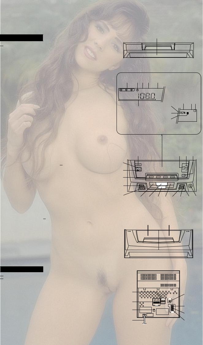
NAMES OF PARTS
1
CD-C405W/CD-C420H

 Front Panel
1. Disc Tray
2.Disc Number Indicator
3.Timer Indicator
4.Record Indicator
5.Sleep Indicator
6.Extra Bass Indicator: X-BASS
7.Function/CD Track/CD Counter/Frequency/Preset Channel/Volume/Timer/Sleep Time Indicator
8.Memory Indicator
9.FM Stereo Mode Indicator: ST
10.FM Stereo Indicator: 
11.CD Play Indicator: 
12.CD Repeat Indicator: 
13.CD Pause Indicator: 

14.Power Switch
15.Extra Bass/Equalizer Mode Button
16.Volume Up/Down Buttons: 

17.Random/Demo Button
18.Clock Button
19.Timer/Sleep Button
20.Function Selector Buttons
21.Memory/Set Button
22.Tuning and Time Up/Down Buttons: 

23.Track Down/Review/Preset Down Button: 


24.Play/Repeat Button: 
25.Stop Button: 
26.Track Up/Cue/Preset Up Button: 


27.Disc Skip Button
28.Open/Close Button: 
29.Record Pause Button: 


30.Headphone Socket
31.(TAPE 1) Cassette Compartment
32.(TAPE 2) Cassette Compartment
CD-C405W

 Rear Panel
1.Video/Auxiliary (Audio Signal) Input Sockets
2.Speaker Terminals
3.AC Voltage Selector
4.AC Power Lead
5.Span Selector Switch
6.FM 75 Ohms Aerial Terminal
7.Aerial Earth Terminal
8.AM aerial Terminal
2 3 4 5 6
1 |
2 |
3 |
REC SLEEP |
X-BASS |
11
7 |
12 |
|
|
|
13 |
8 9 10
MEMORY ST |
kHz |
MHz |
|
14 |
15 16 17 |
18 |
|
|
19 |
|
|
20 |
|
|
21 |
|
|
22 |
23 |
24 25 26 27 28 29 30 |
|
31 |
32 |
1 |
5 |
|
2 |
||
6 |
||
3 |
||
7 |
||
|
||
4 |
8 |
– 3 –
CD-C405W/CD-C420H/CP-C410/CP-C405/CP-SR421
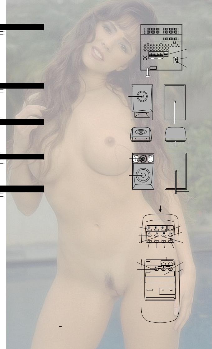
CD-C420H

 Rear Panel
1.Speaker Terminals
2.AC Power Lead
3.Video/Auxiliary (Audio Signal) Input Sockets
4.FM 75 Ohms Aerial Socket
5.AM Loop Aerial Socket
1 |
3 |
|
4 |
||
|
||
2 |
5 |
|
|
CP-C410

 Speaker Section
6.Full Range Speaker
7.Speaker Wire
CP-SR421

 Speaker Section
8.Full Range Speaker
9.Speaker Wire
CP-C405

 Speaker Section
10.Super Tweeter
11.Woofer
12.Speaker Wire
CD-C405W/CD-C420H

 Remote Control
1. remote Control Transmitter LED
 CD Control section
2.Disc Number Select Buttons
3.Track Down/Review Button: 


4.Track Up/Cue Button: 


5.Disc Skip Button
6.Play/Repeat Button: 
7.Stop Button: 
8.Memory Button
9.Clear Button
10.Random Button
11.Pause Button: 

 Tuner control section
12. Preset Up/Down Buttons: 

 Tape control section
13.(TAPE 1/2) Stop Button: 
14.(TAPE 1) Play Button: 
15.(TAPE 2) Record Pause Button: 


16.(TAPE 2) Play Button: 
17.(TAPE 2) Rewind Button: 
18.(TAPE 2) Fast Forward Button: 
19.Function Selector Buttons
20.Extra Bass/Equalizer Mode Button
21.Power Button
22.Volume Up/Down Buttons:

6
7
8
9
10
11
12
1
2  5
5
3 |
|
|
6 |
|
|
|
|
4 |
|
|
7 |
8 |
9 |
10 |
11 |
|
|
12 |
|
13 |
|
|
16 |
14 |
|
|
17 |
15 


 18 19
18 19 


 20 21
20 21

 22
22
– 4 –
– 5 –
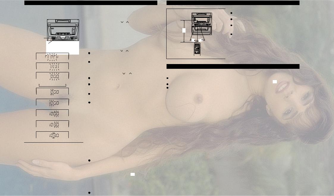
SETTING THE CLOCK
In this example, the clock is set for the 24-hour (0:00) system.
ON/  STAND-BY

CLOCK 
MEMORY/
SET
TUNING/TIME (
 )
)
2
3
4
0:00 
 AM 0:00
 AM 12:00
5
6
7
8
9
1 |
Press the ON/STAND-BY switch to enter the stand-by mode. |
2 |
Press the CLOCK button. |
3 |
Within 3 seconds, press the MEMORY/SET button. |
4 |
Press the TUNING/TIME ( or ) button to select the time |
|
display. |
|
"0:00" |
→ The 24-hour display will appear. |
||
|
|
(0:00 - 23:59) |
||
|
"AM 0:00" → The 12-hour display will appear. |
|||
|
|
(AM 0:00 - PM 11:59) |
||
|
"AM 12:00" → The 12-hour display will appear. |
|||
|
|
(AM 12:00 - PM 11:59) |
||
5 |
Press the MEMORY/SET button. |
|
||
6 |
Press the TUNING/TIME ( |
or |
) button to adjust the hour. |
|
|
Press the TUNING/TIME button once to advance the time by |
|||
|
1 hour. Press for more than 0.5 seconds to advance continu- |
|||
|
ously. |
|
|
|
|
When the 12-hour display is selected, "AM" will change auto- |
|||
7 |
matically to "PM". |
|
|
|
Press the MEMORY/SET button. |
|
|||
8 |
Press the TUNING/TIME ( |
or |
) button to adjust the |
|
|
minutes. |
|
|
|
Press the button for at least 0.5 seconds to change the time in 5 minute intervals.
The hour setting will not advance even if minutes advance from "59" to "00".
9 Press the MEMORY/SET button.
The clock starts operating from "0" seconds. (Seconds are not displayed.)
Note:
In the event of a power failure or when the AC power lead is disconnected, the clock display will go out.
When the AC power supply is restored, the clock display will flash on and off to indicate the time when the power failure occurred or when the AC power lead was disconnected.
If this happens follow the procedure below to change the clock time.
To change the clock time:
When the ON/STAND-BY switch is set to STAND-BY.
1 Press the MEMORY/SET button.
2 Perform steps 6 - 9 above.
When the ON/STAND-BY switch is set to ON.
1 Press the CLOCK button.
2 Within 3 seconds, press the MEMORY/SET button.
3 Perform steps 6 - 9 above.
To see the time display: (When the power is ON)
Press the CLOCK button.
The time display will appear for about 3 seconds.
To switch the time display mode:
1 Press the ON/STAND-BY switch to enter the stand-by mode.
2 Press and hold down the VOLUME button, the

 button and the ON/STAND-BY switch all at the same time. Hold them for at least 2 second.
(Refer to RESETTING THE MICROCOMPUTER on page 16.)
3 Perform steps 1 - 9 above.
Note:
The operation explained above will erase all data stored in memory, such as clock and timer settings, tuner and CD presets.
PREPARATION FOR USE
0.2 m - 6 m (8" - 20') 
15 |
15 |
Notes concerning use:
Replace the batteries if control distance decreases or operation becomes erratic.
Periodically clean the transmitter LED on the remote control and the sensor on the main unit with a soft cloth.
Exposing the sensor on the main unit to strong light may interfere with operation. Change the lighting or the direction of the unit.
Keep the remote control away from moisture, excessive heat, shock, and vibrations.
RESETTING THE MICROCOMPUTER
Reset the microcomputer under the following conditions:-
To erase all of the stored memory contents (clock and timer settings, tuner and CD presets).
If the display is not correct.
If the operation is not correct.
1 Press the ON/STAND-BY (POWER) switch to enter the standby mode.
2 Press and hold down the VOLUME  button, the

 button and the ON/STAND-BY (POWER) switch all at the same time. Hold them for at least 1 second.
MANUAL OPERATION |
C420H/CP-C405W/CD-CD |
|
SR421-C405/CP-C410/CP- |

CD-C405W/CD-C420H/CP-C410/CP-C405/CP-SR421
DISASSEMBLY
Caution on Disassembly
Follow the below-mentioned notes when disassembling the unit and reassembling it, to keep it safe and ensure excellent performance:
1.Take cassette tape and compact disc out of the unit.
2.Be sure to remove the power supply plug from the wall outlet before starting to disassemble the unit.
3.Take off nylon bands or wire holders where they need be removed when disassembling the unit. After servicing the unit, be sure to rearrange the leads where they were before disassembling.
4.Take sufficient care on static electricity of integrated circuits and other circuits when servicing.
CD-C405W/CD-C420H
STEP |
REMOVAL |
|
PROCEDURE |
|
FIGURE |
|
|
|
|
|
|
1 |
Top Cabinet |
1. Screw ..................... |
(A1) x4 |
6-1 |
|
|
|
|
|
|
|
2 |
Side Panel |
1. Screw ..................... |
(B1) x6 |
6-1 |
|
|
(Left/right) |
|
|
|
|
|
|
|
|
|
|
3 |
CD Player Unit/ |
1. |
Turn on the power supply, |
6-2 |
|
|
CD Tray Cover |
|
open the disc tray, take out |
|
|
|
|
|
the CD cover, and close. |
|
|
|
|
|
(Note 1) |
|
|
|
|
2. |
Hook ....................... |
(C1) x3 |
|
|
|
3. |
Hook ....................... |
(C2) x2 |
|
|
|
4. |
Socket .................... |
(C3) x4 |
|
|
|
|
|
|
|
4 |
Back Board |
1. Screw ..................... |
(D1) x5 |
6-2 |
|
|
|
2. |
Screw ..................... |
(D2) x1 |
|
|
|
|
|
|
|
5 |
Main PWB/ |
1. Screw ..................... |
(E1) x12 |
7-1 |
|
|
Display PWB/ |
2. Socket .................... |
(E2) x4 |
|
|
|
Headphone PWB |
|
|
|
|
|
|
|
|
|
|
6 |
Front Panel |
1. Screw ..................... |
(F1) x2 |
7-1 |
|
|
|
2. |
Hook ....................... |
(F2) x2 |
|
|
|
|
|
|
|
7 |
Tape Mechanism |
1. |
Open the cassette holder. |
7-2 |
|
|
|
2. |
Screw...................... |
(G1) x6 |
|
|
|
|
|
|
|
8 |
Turntable |
1. Screw ..................... |
(H1) x1 |
7-3 |
|
|
|
2. |
Cover ...................... |
(H2) x1 |
|
|
|
|
|
|
|
9 |
Disc Tray |
1. |
Screw ..................... |
(J1) x2 |
7-3 |
|
|
2. |
Guide ...................... |
(J2) x2 |
|
|
|
|
|
|
|
10 |
CD Changer |
1. Screw ..................... |
(K1) x4 |
7-4 |
|
|
Mechanism |
|
|
|
|
|
|
|
|
|
|
11 |
CD Mechanism |
1. Screw ..................... |
(L1) x1 |
7-4 |
|
|
|
|
|
|
|
Note 1:
How to open the changer manually. (Fig. 6-3)
1.Insert the tip of fine screwdriver into the hole of CD player base, and press down the worm wheel < A > .
2.Then, turn fully the lock lever in the arrow direction through the hole on the loading chassis bottom in this state.
After that, push forward the CD player base.
CP-C410
STEP |
REMOVAL |
PROCEDURE |
|
FIGURE |
|
|
|
|
|
1 |
Speaker |
1. Front panel ............. |
(A1) x1 |
7-5 |
|
|
2. Screw ..................... |
(A2) x4 |
7-6 |
|
|
|
|
|
CP-SR421
STEP |
REMOVAL |
|
PROCEDURE |
FIGURE |
|
|
|
|
|
1 |
Top cabinet |
1. Screw |
..................... (B1) x6 |
8-1 |
|
|
|
|
|
CP-C405
STEP |
REMOVAL |
PROCEDURE |
|
FIGURE |
|
|
|
|
|
1 |
Speaker |
1. Front panel ............. |
(C1) x1 |
8-2 |
|
|
2. Screw ..................... |
(C2) x4 |
8-3 |
|
|
|
|
|
CD-C405W/CD-C420H |
Illustration: CD-C405W |
( A1 ) x2 |
Top Cabinet |
ø3 x12mm |
|
Side Panel |
|
( A1 ) x2 |
(Right) |
|
ø3 x12mm |
( B1 ) x1 |
|
|
ø3 x12mm |
|
|
( B1 ) x2 |
|
Side Panel |
|
(Left) |
|
ø3 x12mm |
|
|
|
|
|
( B1 ) x2 |
( B1 ) x1 |
|
ø3 x12mm |
ø3 x12mm |
|
|
Figure 6-1 |
|
Hook |
CD Tray Cover |
Hook |
|
( C1) x3 |
|
( C2 ) x1 |
|
|
|
|
|
Push |
|
|
Driver |
|
|
CD Player Unit
Hook
( C2 ) x1
Push |
Driver
( C3 ) x1
( D1 ) x5 |
( C3 ) x3 |
|
ø3 x12mm |
||
|
( D2 ) x1 Back Board ø3 x8mm
Figure 6-2
< A >
LOCK
LEVER
Figure 6-3
– 6 –
 Loading...