


CD-XP500/CD-XP5500
SERVICE MANUAL
No. S1205CDXP500/
MINI COMPONENT SYSTEM
MODEL CD-XP500
CD-XP500 Mini Component System consisting of CD-XP500 (main unit) and CP-XP500 (speaker system).
MINI COMPONENT SYSTEM
MODEL CD-XP5500
CD-XP5500 Mini Component System consisting of CD-XP5500 (main unit) and CP-XP5500 (speaker system).
• In the interests of user-safety the set should be restored to its original condition and only parts identical to those specified be used.
CONTENTS |
|
|
Page |
IMPORTANT SERVICE NOTES (FOR U.S.A. ONLY) ....................................................................................................... |
2 |
SPECIFICATIONS ............................................................................................................................................................. |
3 |
NAMES OF PARTS ........................................................................................................................................................... |
4 |
OPERATION MANUAL ...................................................................................................................................................... |
6 |
QUICK GUIDE ................................................................................................................................................................... |
8 |
DISASSEMBLY ................................................................................................................................................................ |
10 |
REMOVING AND REINSTALLING THE MAIN PARTS ................................................................................................... |
13 |
ADJUSTMENT ................................................................................................................................................................. |
14 |
NOTES ON SCHEMATIC DIAGRAM .............................................................................................................................. |
18 |
TYPES OF TRANSISTOR AND LED ............................................................................................................................... |
18 |
BLOCK DIAGRAM ........................................................................................................................................................... |
19 |
SCHEMATIC DIAGRAM / WIRING SIDE OF P.W.BOARD ............................................................................................. |
22 |
VOLTAGE ........................................................................................................................................................................ |
39 |
WAVEFORMS OF CD CIRCUIT ...................................................................................................................................... |
40 |
TROUBLESHOOTING ..................................................................................................................................................... |
41 |
FUNCTION TABLE OF IC ................................................................................................................................................ |
45 |
FL DISPLAY ..................................................................................................................................................................... |
51 |
REPLACEMENT PARTS LIST/EXPLODED VIEW |
|
PACKING OF THE SET (FOR U.S.A. ONLY) |
|
This document has been published to be used
SHARP CORPORATION for after sales service only.
The contents are subject to change without notice.
CD-XP500/CD-XP5500
IMPORTANT SERVICE NOTES (FOR U.S.A. ONLY)
BEFORE RETURNING THE AUDIO PRODUCT
(Fire & Shock Hazard)
Before returning the audio product to the user, perform the following safety checks.
1.Inspect all lead dress to make certain that leads are not pinched or that hardware is not lodged between the chassis and other metal parts in the audio product.
2.Inspect all protective devices such as insulating materials, cabinet, terminal board, adjustment and compartment covers or shields, mechanical insulators etc.
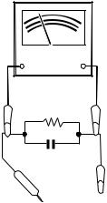
3.To be sure that no shock hazard exists, check for leakage
current in the following manner.
*Plug the AC line cord directly into a 120 volt AC outlet.
*Using two clip leads, connect a 1.5 kohm, 10 watt resistor paralleled by a 0.15 μF capacitor in series with all exposed metal cabinet parts and a known earth ground, such as conduit or electrical ground connected to earth ground.
*Use a VTVM or VOM with 1000 ohm per volt, or higher, sensitivity to measure the AC voltage drop across the resistor (See diagram).
*Connect the resistor connection to all exposed metal parts having a return path to the chassis (antenna, metal cabinet, screw heads, knobs and control shafts, escutcheon, etc.) and measure the AC voltage drop across the resistor.
VTVM |
AC SCALE |
1.5 kohms
10 W
0.15 F
TEST PROBE
TO EXPOSED
METAL PARTS
CONNECT TO KNOWN EARTH GROUND
All check must be repeated with the AC line cord plug connection reversed.
Any reading of 0.3 volt RMS (this corresponds to 0.2 milliamp. AC.) or more is excessive and indicates a potential shock hazard which must be corrected before returning the audio product to the owner.
– 2 –

CD-XP500/CD-XP5500
FOR A COMPLETE DESCRIPTION OF THE OPERATION OF THIS UNIT, PLEASE REFER TO THE OPERATION MANUAL.
SPECIFICATIONS
CD-XP500/CD-XP5500
 General
Power source |
AC 120 V, 60 Hz |
|
|
Power consumption |
130 W |
|
|
Dimensions |
Width: 10-5/8" (270 mm) |
|
Height: 13" (330 mm) |
|
Depth: 14-3/16" (360 mm) |
|
|
Weight |
17.4 lbs. (7.9 kg) |
|
|
 Amplifier
Output power |
150 watts minimum RMS per channel into 6 ohms from |
|
|
60 Hz to 20 kHz, |
10% total harmonic distortion |
Output terminals |
Speakers: 6 ohms |
|
|
Headphones: 16 |
- 50 ohms (recommended: 32 ohms) |
|
|
|
Input terminals |
Video/Auxiliary (audio signal): 500 mV/47 kohms |
|
|
|
|
 CD player
Type |
3-disc multi-play compact disc player |
|
|
Signal readout |
Non-contact, 3-beam semiconductor laser pickup |
|
|
D/A converter |
1-bit D/A converter |
Frequency response |
20 - 20,000 Hz |
|
|
Dynamic range |
90 dB (1 kHz) |
|
|
 Tuner
Tuner
Frequency range |
FM: 87.5 - 108 MHz |
|
AM: 530 - 1,720 kHz |
|
|
 Cassette deck
Frequency response |
50 - 14,000 Hz (Normal tape) |
|
Signal/noise ratio |
55 dB (TAPE 1, playback) |
|
|
50 dB (TAPE 2, recording/playback) |
|
|
|
|
Wow and flutter |
0.3 % (WRMS) |
|
|
|
|
|
|
|
CP-XP500/CP-XP5500 |
|
|
|
|
|
Type |
Twin-Drive speaker system |
|
|
2" (5 cm) Tweeter |
|
|
5-1/8" (13 cm) Woofer 2 |
|
Maximum input power |
300 W |
|
Rated input power |
150 W |
|
|
|
|
Impedance |
6 ohms |
|
|
|
|
Dimensions |
Width: 8-11/16" (220 mm) |
|
|
Height: 13" (330 mm) |
|
|
Depth: 11" (280 mm) |
|
|
|
|
Weight |
10.3 lbs. (4.7 kg)/each |
|
|
|
|
Specifications for this model are subject to change without prior notice.
– 3 –
CD-XP500/CD-XP5500
NAMES OF PARTS
CD-XP500/CD-XP5500

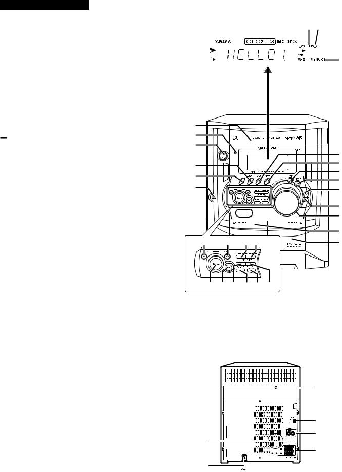
 Display
1.CD Pause Indicator
2.Extra Bass Indicator
3.Disc Number Indicators
4.Tape 2 Record Indicator
5.FM Stereo Mode Indicator
6.FM Stereo Receiving Indicator
7.Timer Play Indicator
8.Sleep Indicator
9.Timer Recording Indicator
10.CD Play Indicator
11.CD Repeat Play Indicator
12.Tape Play Indicator
13.Memory Indicator

 Front panel
1.Disc Tray
2.Timer Set Indicator
3.Power On/Stand-by Button
4.Tuner (Band) Button
5.CD Button
6.Headphone Jack
7.Tape (1 2) Button
8.Video/Auxiliary Button
9.Equalizer Mode Select Button 10. Extra Bass/Demo Mode Button 11. Disc Tray Open/Close Button 12. Disc Skip Button
13. Volume Control
14. Tape 1 Cassette Compartment
15. Tape 2 Cassette Compartment
16. CD Track Down or Fast Reverse, Tape 2 Rewind, Tuner Preset Down Button
17. CD Track Up or Fast Forward, Tape 2 Fast Forward, Tuner Preset Up Button
18. Clock Button
19. Timer/Sleep Button
20. CD Play or Repeat, Tape Play Button (with Indicator) 21. CD or Tape Stop Button (with Indicator)
22. Tuning and Time Down Button
23. Memory/Set Button
24. Tape 2 Record Pause Button
25. Tuning and Time Up Button
 Rear panel
1.Cooling Fan
2.AC Power Cord
3.Transport Screw
4.FM/AM Loop Antenna Jack
5.Video/Auxiliary (Audio Signal) Input Jacks
6.Speaker Terminals
1 |
2 |
3 |
4 |
5 6 7 8 |
9 |
|
|
||||||||||
10 |
|
|
|
|
|
|
|
|
|
|
|
|
|
|
|
|
12 |
|
|
|
|
|
|
|
|
|
|
|
|
|
|
|
|
||
|
|
|
|
|
|
|
|
|
|
|
|
|
|
|
|
||
|
|
|
|
|
|
|
|
|
|
|
|
|
|
|
|
||
|
|
|
|
|
|
|
|
|
|
|
|
|
|
|
|
||
11 |
|
|
|
|
|
|
|
|
|
|
|
|
|
|
|
13 |
|
|
|
|
|
|
|
|
|
|
|
|
|
|
|
|
|||
1 |
|
|
|
2 |
|
|
|
3 |
|
|
|
|
|
|
7 |
4 |
|
|
8 |
|
|
9 |
|
5 |
|
|
|
|
|
10 |
|
6 |
|
|
|
|
|
11 |
|
|
|
|
|
|
|
|
12 |
|
|
|
13 |
|
|
|
14 |
16 |
17 |
18 19 |
15 |
20 21 22 23 24 25
3
4
5
1
6
2
– 4 –
CD-XP500/CD-XP5500
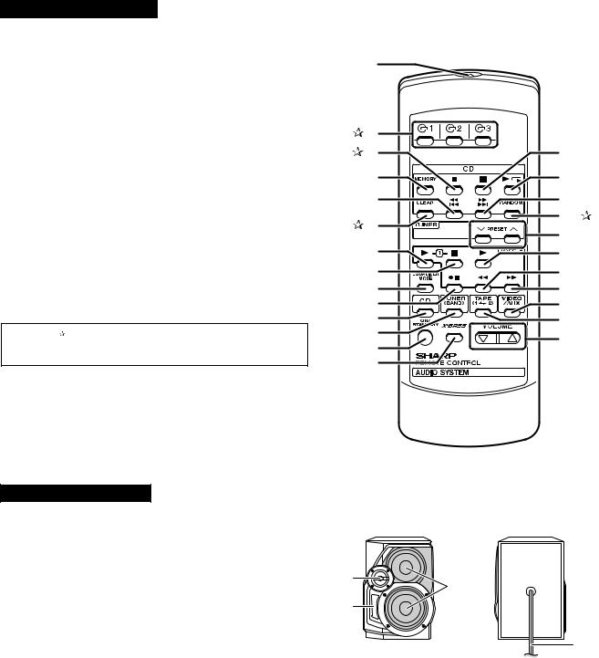
 Remote control
1.Remote Control Transmitter
2.Disc Number Select Buttons
3.CD Pause Button
4.CD Memory Button
5.CD Track Down or Fast Reverse Button
6.CD Clear Button
7.Tape 1 Play Button
8.Tape 1/Tape 2 Stop Button
9.Equalizer Mode Select Button
10.Tape 2 Record Pause Button
11.CD Button
12.Tuner (Band) Button
13.Power On/Stand-by Button
14.Extra Bass Button
15.CD Stop Button
16.CD Play or Repeat Button
17.CD Track Up or Fast Forward Button
18.CD Random Button
19.Tuner Preset Up and Down Buttons
20.Tape 2 Play Button
21.Tape 2 Rewind Button
22.Tape 2 Fast Forward Button
23.Video/Auxiliary Button
24.Tape (1 2) Button
25.Volume Up and Down Buttons
Buttons with " " mark in the illustration can be operated on the remote control only.
Other buttons can be operated both on the main unit and the remote control.
CD-XP500/CD-XP5500
1 |
|
|
2 |
|
|
3 |
15 |
|
4 |
16 |
|
5 |
17 |
|
6 |
18 |
|
19 |
||
|
||
7 |
20 |
|
8 |
21 |
|
9 |
22 |
|
10 |
23 |
|
11 |
24 |
|
12 |
25 |
|
13 |
||
|
||
14 |
|
CP-XP500/CP-XP5500
1.Tweeter
2.Bass Reflex Duct
3.Woofer
4.Speaker Wire
1
3
2
4
– 5 –
CD-XP500/CD-XP5500
OPERATION MANUAL
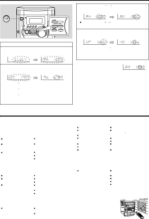
Setting the clock
In this example, the clock is set for the 12-hour (AM 12:00) display.
1 Press the ON/STAND-BY button to turn the power on.
2 Press the CLOCK button and within 5 seconds, press the MEMORY/SET button.
3 Press the TUNING/TIME ( or
or  ) button to select 12-hour or 24hour display and then press the MEMORY/SET button.
"AM 12:00" The 12-hour display will appear.
(AM 12:00 - PM 11:59)
"AM 0:00" The 12-hour display will appear.
(AM 0:00 - PM 11:59)
"0:00" The 24-hour display will appear.
(0:00 - 23:59)
Note that this can only be set when the unit is first installed or it has been reset. [Refer to "Clearing all the memory (reset)".]
4 Press the TUNING/TIME( |
or |
)button to adjust the hour and then |
press the MEMORY/SET button. |
||
Press the TUNING/TIME ( |
or |
) button once to advance the time by 1 hour. |
Hold it down to advance continuously.
 When the 12-hour display is selected, "AM" will change automatically to "PM".
5 Press the TUNING/TIME ( or
or ) button to adjust the minutes and then press the MEMORY/SET button.
 Press the TUNING/TIME(
 or ) button once to advance the time by 1 minute. Hold it down to change the time in 5-minute intervals.
 The hour will not advance even if minutes advance from "59" to "00".
 The clock begins counting from "0" seconds. (Seconds are not displayed.) The time display will disappear after a few seconds.
To confirm the time display:
Press the CLOCK button.
The time display will appear for about 5 seconds.
Note:
The "CLOCK" or time will flash at the push of the CLOCK button when the AC power supply is restored after a power failure or unplugging the unit.
Readjust the clock as follows.
To readjust the clock:
Perform "Setting the clock" from step 1. If the time display is flashing, step 3 (for selecting the 12-hour or 24-hour display) will be skipped.
To change the 12-hour or 24-hour display:
1Clear all the programmed contents. [Refer to "Clearing all the memory (reset)".]
2Perform "Setting the clock" from step 1.
Troubleshooting chart
Many potential problems can be resolved by the owner without calling a service technician.
If something is wrong with this product, check the following before calling your authorized SHARP dealer or service center.
 General
Symptom |
Possible cause |
|
|
The clock is not on time. |
Did a power failure occur? Reset the |
|
clock. |
|
|
When a button is pressed, the unit |
Set this unit to the power stand-by mode |
does not respond. |
and then turn it back on. |
|
If the unit still malfunctions, reset it. |
|
|
No sound is heard. |
Is the volume level set to "0"? |
|
Are the headphones connected? |
|
Are the speaker wires disconnected? |
|
|
 Cassette deck
Symptom |
Possible cause |
Cannot record. |
Is the erase-prevention tab removed? |
|
|
Cannot record tracks with proper |
Is it a normal tape? (You cannot record on |
sound quality. |
a metal or CrO tape.) |
Cannot erase completely. |
|
|
|
Sound skipping. |
Is there any slack? |
|
Is the tape stretched? |
Cannot hear treble. |
Are the capstans, pinch rollers, or heads |
Sound fluctuation. |
dirty? |
|
|
|
|
Cannot remove the tape. |
If a power failure occurs during playback, |
|
the heads remain engaged with the tape. |
|
Do not open the compartment forcibly. |
|
Wait until electricity resumes. |
|
|
 CD player
Symptom |
Possible cause |
|
|
Playback does not start. |
Is the disc loaded upside down? |
Playback stops in the middle or is |
Does the disc satisfy the standards? |
not performed properly. |
Is the disc distorted or scratched? |
|
|
|
|
Playback sounds are skipped, or |
Is the unit located near excessive vibra- |
stopped in the middle of a track. |
tions? |
|
Is the disc very dirty? |
|
Has condensation formed inside the unit? |
|
|
 Tuner
Tuner
Symptom |
Possible cause |
|
|
Radio makes unusual noise con- |
Is the unit placed near the TV or comput- |
secutively. |
er? |
|
Is the FM/AM loop antenna placed proper- |
|
ly? Move the AC power cord away from |
|
the antenna if located near. |
|
|
 Remote control
Symptom |
Possible cause |
|
|
The remote control does not oper- |
Is the AC power cord of the unit plugged |
ate. |
in? |
|
Is the battery polarity respected? |
|
Are the batteries dead? |
|
Is the distance or angle incorrect? |
|
Does the remote control sensor receive |
|
strong light? |
|
|
 Condensation
Sudden temperature changes, storage or operation in an extremely humid environment may cause condensation inside the cabinet (CD pick-
up, tape heads, etc.) or on the transmitter on the 


 remote control.


 Condensation can cause the unit to malfunction.
 If this happens, leave the power on with no disc


 (or cassette) in the unit until normal playback is


 possible (about 1 hour). Wipe off any condensa-
tion on the transmitter with a soft cloth before operating the unit.
– 6 –
Troubleshooting chart
 If trouble occurs
When this product is subjected to strong external interference (mechanical shock, excessive static electricity, abnormal supply voltage due to lightning, etc.) or if it is operated incorrectly, it may malfunction.
If such a problem occurs, do the following:
1Set the unit to the stand-by mode and turn the power on again.
2If the unit is not restored in the previous operation, unplug and plug in the unit, and then turn the power on.
Note:
If neither operation above restores the unit, clear all the memory by resetting it.
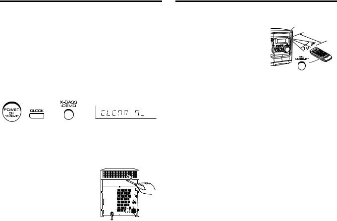
 Clearing all the memory (reset)
1Press the ON/STAND-BY button to enter the power stand-by mode.
2While pressing down the CLOCK button and the X-BASS/DEMO button, press the ON/STAND-BY button until "CLEAR AL" appears.
Caution:
This operation will erase all data stored in memory including clock, timer settings, tuner preset, and CD program.
 Before transporting the unit
On the back of this unit is equipped with a transport screw in order to prevent damage during transportation.
1 Press the ON/STAND-BY button to turn the
power on.
2 Press the CD button. 3 Press the  OPEN/CLOSE button to open
the disc tray.
Remove all CDs inserted in the unit.
4 Press the  OPEN/CLOSE button to close the disc tray.
Make sure that "NO DISC" is displayed.
5 Press the ON/STAND-BY button to enter the stand-by mode, and then unplug the AC power cord from the AC outlet.
6 Insert the transport screw into the back of the unit and tighten it with a flat head screwdriver or a coin.
CD-XP500/CD-XP5500
Remote control
 Test of the remote control
Point the remote control directly at the remote |
Remote sensor |
sensor on the unit. |
|
|
8" - 20' |
The remote control can be used within |
(0.2 m - 6 m) |
the range shown: |
|
Press the ON/STAND-BY button. Does the pow- |
|
er turn on? Now, you can enjoy the music. |
|
– 7 –
 1
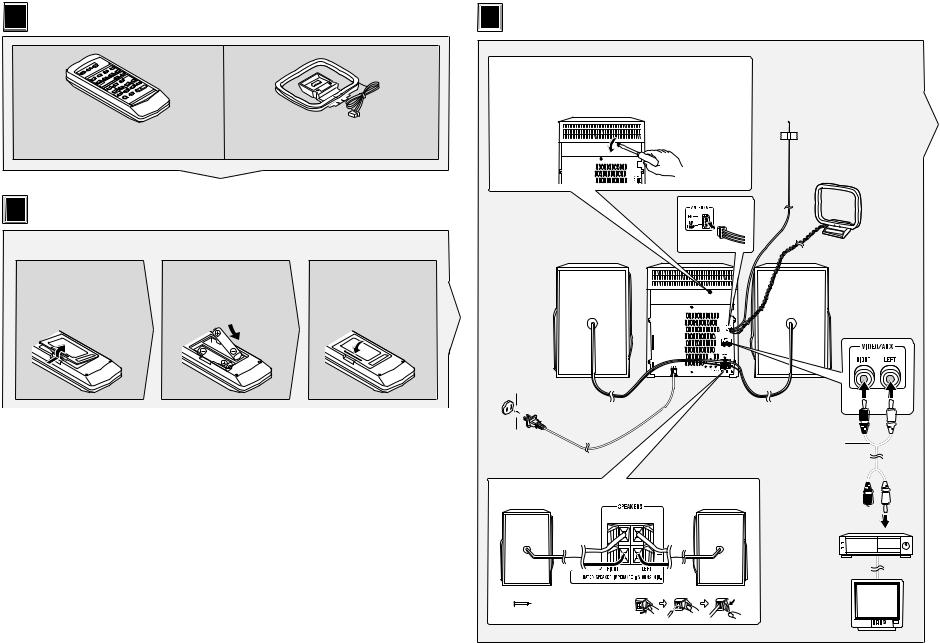
1 AccessoriesAccesorios
Remote control × 1 |
FM/AM loop antenna × 1 |
Controlador remoto × 1 |
Antena de cuadro de FM/AM × 1 |
2 |
Remote control battery installation |
|
|
Instalación de las pilas del controlador remoto |
|||
Use 2 “AA” size batteries (UM/SUM-3, R6, HP-7 or similar). |
Batteries are not included. |
||
Use dos pilas del tamaño “AA” (UM/SUM-3, R6, HP-7 o equivalentes). |
Las pilas no están incluidas. |
||
|
1 Remove the |
2 Insert the batteries |
3 Replace the cover. |
|
battery cover. |
as shown. |
|
|
Extraiga la cubierta |
Inserte las pilas |
Vuelva a colocar la |
|
de las pilas. |
como se muestra. |
cubierta. |
– 8 –
3 System connections
 Conexiones del sistema
Before turning the power on, be sure to remove this transport screw on the back of the unit using a flat head screwdriver or a coin.
Antes de conectar la alimentación, asegúrese de extraer este tornillo para el transporte de la parte posterior del aparato empleando un destornillador de punta plana o una moneda.
FM antenna
Antena de FM
AM loop antenna
Antena de cuadro de AM
Right speaker
Altavoz derecho
AC outlet
(AC 120 V, 60 Hz)
A un tomacorriente de CA (120 V de CA, 60 Hz)
Right speaker
Altavoz derecho
Red 
 Black
Black
Rojo Negro
Left speaker
Altavoz izquierdo
GUIDE QUICK
Left speaker
Altavoz izquierdo
RCA cord (not supplied)
Cable RCA
(no suministrado)
To the line output jacks
A las tomas de  salida de línea
VCR, DVD, etc.
Videograbadora, DVD, etc.
TV
TV
XP5500-XP500/CD-CD
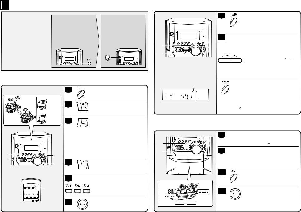
4 |
Turn on your system |
Conexión de la alimentación de su sistema |
The first time the unit is plugged in, the unit will enter the demonstration mode. You will see words scroll.
Cuando se enchufe por primera vez el aparato, se establecerá en el modo de demostración. Verá un desplazamiento de palabras.
1 Press the X-BASS/DEMO button to cancel the demonstration mode.
Pulse el botón X-BASS/DEMO para cancelar el modo de demostración.
2 Press the ON/STAND-BY button to turn the power on.
Pulse el botón
ON/STAND-BY para conectar la alimentación.
– 9 –
Listening to a CD (CDs)
Audición de un disco CD (discos CD)
1
5” (12 cm)
12 cm
2
3” (8 cm)
8 cm
3
1 |
2, 4 |
|
|
6 |
|
||
3 |
4 |
||
|
5
5
6
Press the CD button.
Pulse el botón CD.
Press the  OPEN/CLOSE button to open the disc tray.
Pulse el botón  OPEN/CLOSE para abrir la bandeja de discos.
Place the CD(s) on the disc tray, label side up.
When loading a third disc, press the DISC SKIP button to turn the disc tray, then place the CD in the open position.
Coloque el disco compacto en la bandeja de discos, con el lado de la etiqueta hacia arriba.
Cuando ponga un tercer disco, pulse el botón DISC SKIP para girar la bandeja de discos, y coloque el disco compacto en la posición abierta.
Press the  OPEN/CLOSE button to close the disc tray.
Pulse el botón  OPEN/CLOSE para cerrar la bandeja de discos.
To select the CD you want to listen to first, press one of  1 -
1 -  3 buttons on the remote control.
Para seleccionar el disco CD que desee escuchar primero, pulse uno de los botones  1 -
1 -  3 del controlador remoto.
Press the 
 button to start playback.
Pulse el botón 
 para iniciar la reproducción.
Listening to the radio
Audición de la radio
1
2
1
2
FM stereo mode indicator
Indicador del modo de FM en estéreo
FM stereo receiving indicator
Indicador de recepción de FM en estéreo
Press the TUNER (BAND) button repeatedly to select the desired frequency band (FM or AM).
Pulse repetidamente el botón TUNER (BAND) para seleccionar la banda de frecuencias deseada (FM o AM).
Press the TUNING/TIME ( or
or  ) button to tune in to the desired station. When the TUNING/TIME button is pressed for more than 0.5 seconds, scanning will start automatically and the tuner will stop at the first receivable broadcast station.
Pulse el botón TUNING/TIME ( o ) para sintonizar la emisora deseada.
Cuando se pulse el botón TUNING/TIME durante más de 0,5 segundos, la exploración se iniciará automáticamente y el sintonizador se parará en la primera emisora difusora que pueda recibirse.
To receive an FM stereo transmission:
Press the TUNER (BAND) button to display the “ST” indicator.
●“ ” will appear when an FM broadcast is in stereo.
Para recibir una transmisión de FM en estéreo: Pulse el botón TUNER (BAND) para que se visualice el indicador “ST”.
●“ ” aparecerá cuando una difusión de FM sea en estéreo.
Listening to a cassette tape (TAPE 1 or TAPE 2)
Audición de una cinta de cassette (TAPE 1 o TAPE 2)
1
3
4 |
2 |
3
1, 2
4
Open the cassette door by pushing the area marked “  PUSH EJECT”.
Abra la puerta del cassette pulsando la parte marcada “ PUSH EJECT”.
Load a cassette into the TAPE 1 or TAPE 2 cassette compartment with the side to be played facing toward you.
Cargue un cassette en el compartimiento de cassette de TAPE 1 o de TAPE 2 con la cara a reproducirse encarada hacia usted.
Press the TAPE (1  2) button to select the cassette you want to listen to.
Pulse el botón TAPE (1  2) para seleccìonar el cassette que desee escuchar.
Press the 
 button to start playback.
Pulse el botón 
 para iniciar la reproducción.
TAPE 1 |
TAPE 2 |
XP5500-XP500/CD-CD
CD-XP500/CD-XP5500
DISASSEMBLY
Caution on Disassembly
Follow the below-mentioned notes when disassembling the unit and reassembling it, to keep it safe and ensure excellent performance:
1.Take cassette tape and compact disc out of the unit.
2.Be sure to remove the power supply plug from the wall outlet before starting to disassemble the unit.
3.Take off nylon bands or wire holders where they need to be removed when disassembling the unit. After servicing the unit, be sure to rearrange the leads where they were before disassembling.
4.Take sufficient care on static electricity of integrated circuits and other circuits when servicing.
CD-XP500/CD-XP5500
STEP |
REMOVAL |
|
|
PROCEDURE |
FIGURE |
|||
|
|
|
|
|
|
|
|
|
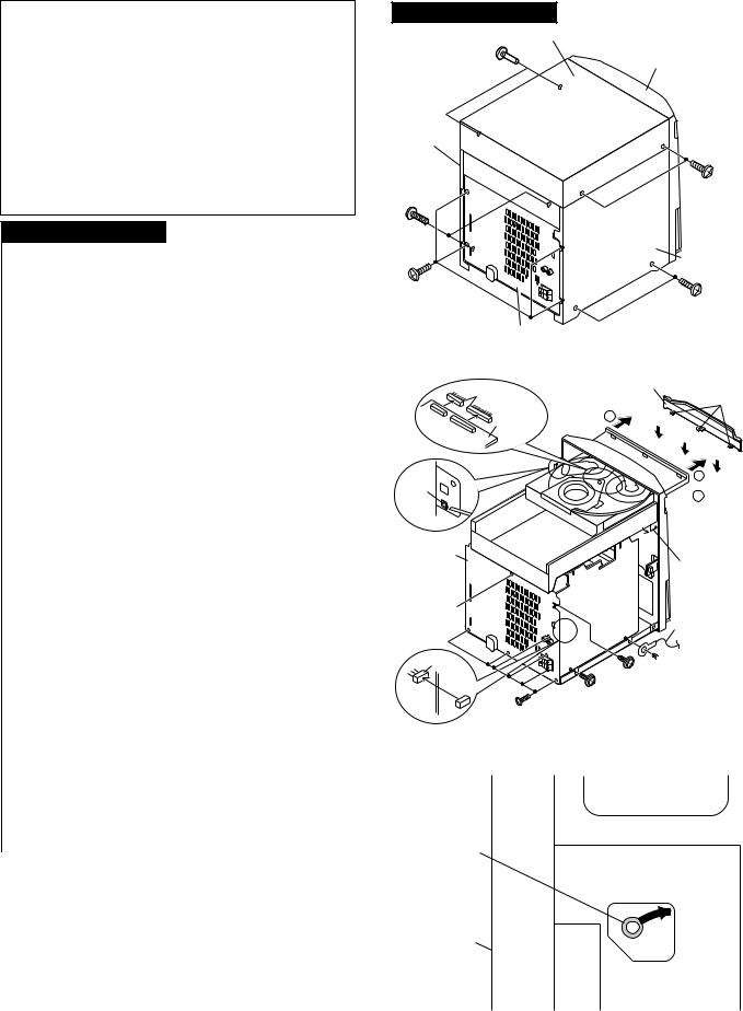
1 |
Top Cabinet |
1. |
Screw ...................... |
(A1) x4 |
10-1 |
|||
2 |
Side Panel |
1. |
Screw ...................... |
(B1) x8 |
10-1 |
|||
|
(Left/Right) |
|
|
|
|
|
|
|
|
|
|
|
|
|
|
|
|
3 |
CD Tray Cover/ |
1. |
Turn on the power supply, |
.. |
|
10-2 |
||
|
CD Player Unit |
|
open the disc tray, take out |
|
|
|||
|
|
|
the CD tray cover, and close. |
|
||||
|
|
|
(Note 1) |
|
|
|
|
|
|
|
2. |
Screw ...................... |
(C1) x1 |
|
|||
|
|
3. |
Hook ........................ |
(C2) x3 |
|
|||
|
|
4. |
Hook ........................ |
(C3) x2 |
|
|||
|
|
5. |
Socket ..................... |
(C4) x2 |
|
|||
|
|
|
|
|
|
|
|
|
4 |
Rear Panel with |
1. |
Screw ...................... |
(D1) x7 |
10-2 |
|||
|
Fan Motor |
2. |
Socket ..................... |
(D2) x1 |
|
|||
5 |
Main PWB |
1. |
Screw ...................... |
(E1) x3 |
10-2, 11-1 |
|||
|
|
2. |
Socket ..................... |
(E2) x3 |
11-1 |
|||
|
|
3. |
Flat Cable ............... |
(E3) x1 |
|
|||
|
|
4. |
Flat Wire .................. |
(E4) x1 |
|
|||
|
|
|
|
|
|
|
|
|
6 |
Front Panel |
1. |
Screw ....................... |
(F1) x2 |
11-1 |
|||
|
|
2. |
Hook ......................... |
(F2) x2 |
|
|||
|
|
3. |
Socket ...................... |
(F3) x1 |
|
|||
|
|
|
|
|
|
|
|
|
7 |
Display PWB |
1. Knob ........................ |
(G1) x1 |
11-2 |
||||
|
|
2. |
Screw .................... |
(G2) x16 |
|
|||
|
|
3. |
Flat Cable ............... |
(G3) x1 |
|
|||
8 |
Tape Mechanism |
1. |
Open the cassette holder |
|
|
11-2 |
||
.. |
||||||||
|
|
2. |
Screw...................... |
(H1) x5 |
|
|||
|
|
|
|
|
|
|
|
|
9 |
Headphones PWB |
1. |
Screw ....................... |
(J1) x1 |
11-2 |
|||
10 |
Turntable |
1. |
Hook ........................ |
(K1) x2 |
11-3 |
|||
|
|
2. |
Cover ...................... |
(K2) x1 |
|
|||
|
|
|
|
|
|
|
|
|
11 |
Loading Tray |
1. |
Turn fully the lock |
lever in the |
10-3 |
|||
|
|
|
arrow direction. |
|
|
|
|
|
|
|
2. |
Push the loading tray backward |
11-4 |
||||
|
|
|
to engage the claw with the |
|
||||
|
|
|
groove and remove it in the |
|
||||
|
|
|
direction of the arrow. .. (L1) x6 |
|
||||
|
|
|
|
|
|
|
|
|
12 |
CD Servo PWB |
1. |
Screw ...................... |
(M1) x2 |
11-5 |
|||
|
(Note 2) |
2. |
Hook ........................ |
(M2) x1 |
|
|||
|
|
3. |
Socket ..................... |
(M3) x4 |
|
|||
13 |
CD Mechanism |
1. |
Hook ........................ |
(N1) x2 |
11-6 |
|||
|
|
2. |
Hook ........................ |
(N2) x2 |
|
|||
|
|
|
|
|
|
|
|
|
Note 1: How to open the changer manually. (Fig. 10-3)
1.In this state, turn fully the lock lever in the arrow direction through the hole on the loading tray bottom.
2.After that, push forward the loading tray.
Note 2:
1. After removing the connector for the optical pickup from the connector, wrap the conductive aluminium foil around the front end of the connector so as to protect the optical pickup from electrostatic damage.
Note 3:
1.Be careful not to break the claw of the CD mechanism.
2.When fining back the cam gear assembly, let it lock by front movement.
CD-XP500/CD-XP5500
Top Cabinet
Front (A1)x2 
 Panel ø3x12mm
Side Panel (Right)
(B1)x2 |
(A1)x2 |
ø3x10mm |
ø3x12mm |
Side Panel (Left)
(B1)x4 |
(B1)x2 |
ø3x10mm |
|
|
ø3x10mm |
Rear
Panel
Figure 10-1
(C4)x2
CD Servo
PWB
(C3)x1
Pull
Rear
Panel
(C1)x1  ø3x10mm
(D2)x1
Main PWB 
(D1)x6
ø3x10mm
CD Tray Cover
(C2)x3
1
1
 2
2
 CD Player
Unit
(C3)x1
 Main PWB
Lug Wire
 (E1)x1
(D1)x1 ø3x10mm
ø3x10mm
(E1)x1
ø3x10mm
Figure 10-2
Lock Lever
CD Player Unit
(Bottom View)
Figure 10-3
– 10 –

CD-XP500/CD-XP5500
(E2)x2 |
(L1)x3 |
Loading Tray |
(E3)x1
3
(E1)x1
ø3x10mm |
|
|
(E2)x1 |
|
|
(F3)x1 |
Front |
2 |
|
Panel |
|
Power PWB |
|
|
|
|
|
(F2)x1 |
Headphones |
|
PWB |
|
|
|
|
1 |
Transformer |
|
|
PWB |
(E4)x1 |
|
(L1)x3
Main PWB
(F2)x1
Figure 11-4
(F1)x2
ø3x10mm
Figure 11-1 |
(M1)x2 |
|
ø3x10mm |
(G3)x1 |
|
|
Loading |
|
|
CD Servo |
Tray |
||
|
Front Panel |
(M3)x2 |
||
|
PWB |
|
||
|
(G1)x1 |
|
||
Display PWB |
|
|
|
|
|
(M2)x1 |
|
|
|
|
|
|
|
|
(G2)x16 |
|
|
|
|
ø3x10mm |
|
|
|
|
Tape |
|
|
|
|
Mechanism |
Open |
|
|
|
(H1)x5 |
|
|
|
|
ø3x10mm |
|
|
|
|
Headphones |
|
(M3)x2 |
|
|
|
|
|
|
|
PWB |
|
|
|
|
|
|
|
Figure 11-5 |
|
|
Cassette |
|
|
|
Lug Wire |
Holder |
CD |
|
(N2)x2 |
(J1)x1 |
|
Mechanism |
||
|
|
|||
ø3x10mm
Figure 11-2
(K2)x1 
(N1)x1
(N1)x1
Loading Tray
Turntable
Loading
Tray
(K1)x2
Figure 11-6
CD Player Unit
Figure 11-3
– 11 –
CD-XP500/CD-XP5500
CP-XP500/CP-XP5500
STEP |
REMOVAL |
PROCEDURE |
|
FIGURE |
|
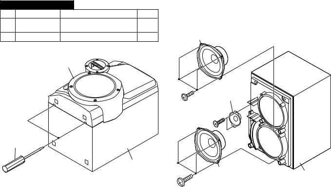
1 |
Woofer |
1. Front Panel ............. |
(A1) x1 |
12-1 |
|
|
|
2. Screw ...................... |
(A2) x8 |
12-2 |
|
2 |
Tweeter |
1. Screw ...................... |
(B1) x2 |
12-2 |
Woofer |
|
|
(A1)x1 |
|
|
|
Tweeter
(A2)x4
ø4x12mm (B1)x2 ø3x10mm
Screwdriver
Driver should |
Speaker Box |
|
|
be pried away |
Woofer |
Speaker Box |
|
from Speaker Box. |
(A2)x4 |
||
|
|||
|
|
||
|
ø4x12mm |
|
|
Figure 12-1 |
|
Figure 12-2 |
– 12 –
CD-XP500/CD-XP5500
REMOVING AND REINSTALLING THE MAIN PARTS
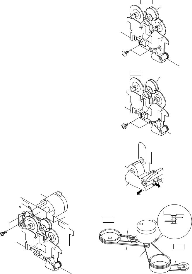
TAPE MECHANISM SECTION
Perform steps 1 to 6 and 8 of the disassembly method to remove the tape mechanism.
How to remove the record/playback and erase heads (TAPE 2) (See Fig. 13-1)
1.When you remove the screws (A1) x 2 pcs., the recording/ playback head and three-dimensional head of the erasing head can be removed.
How to remove the playback head (TAPE 1) (See Fig. 13-2)
1.When you remove the screws (B1) x 2 pcs., the playback head can be removed.
How to remove the pinch roller (TAPE 1/2) (See Fig. 13-3)
1. Carefully bend the pinch roller pawl in the direction of the arrow <A>, and remove the pinch roller (C1) x 1 pc., in the direction of the arrow <B>.
Note:
When installing the pinch roller, pay attention to the spring mounting position.
How to remove the belt (TAPE 2) (See Fig. 13-4)
1.Remove the main belt (D1) x 1 pc., from the motor side.
2.Remove the FF/REW belt (D2) x 1 pc.
How to remove the belt (TAPE 1) (See Fig. 13-4)
1.Remove the main belt (E1) x 1 pc., from the motor side.
2.Remove the FF/REW belt (E2) x 1 pc.
How to remove the motor (See Fig. 13-5)
1. Remove the screws (F1) x 2 pcs., to remove the motor.
Motor
Clutch Ass'y
(F1)x2
Ø 2.6x5mm
TAPE 2
Clutch Ass'y
Record/Playback
Head
Erase Head 

 (A1)x2 Ø2x9mm
Figure 13-1
TAPE 1
Clutch Ass'y
Playback
Head
(B1)x2
Ø2x9mm
Figure 13-2
|
|
|
Pinch |
|
|
Pinch Roller |
|
Roller |
|
|
<A> |
Pawl |
|
|
|
(C1)x1 |
|
||
|
|
|
|
|
|
Pull |
<B> |
|
|
|
|
|
|
|
|
|
Figure 13-3 |
|
|
|
|
|
Motor |
|
TAPE 2 |
FF/REW |
Motor |
|
TAPE 1 |
|
|
|||
|
Belt |
TAPE 2 |
Main Belt |
|
|
(D2)x1 |
(E1)x1 |
||
|
Main Belt |
|||
|
|
|
||
|
|
(D1)x1 |
|
|
|
TAPE 1 |
Main Belt |
FF/REW |
(D1)x1 |
Belt |
Main Belt |
(E2)x1 |
(E1)x1 |
|
Figure 13-5 |
Figure 13-4 |
– 13 –
CD-XP500/CD-XP5500
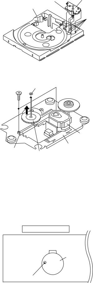
CD MECHANISM SECTION
Perform steps 1, 2, 3, 10, 11,12 and 13 of the disassembly method to remove the CD mechanism.
How to remove the loading motor (See Fig. 14-1)
1. Bend the hooks (A1) x 6 pcs., to remove the loading motor.
Loading |
Loading |
|
Motor PWB |
||
Motor |
||
|
||
Loading |
|
|
Tray |
|
|
|
(A1)x6 |
Figure 14-1
How to remove the pickup (See Fig. 14-2)
1.Remove the stop washer (B1) x 1 pc., to remove the gear (B2) x 1 pc.
2.Remove the screws (B3) x 2 pcs., to remove the shaft (B4) x 1 pc.
3.Remove the pickup.
Note
After removing the connector for the optical pickup from the connector wrap the conductive aluminium foil around the front end of connector so as to protect the optical pickup from electrostatic damage.
(B3)x2 |
Stop Washer |
|
(B1)x1 |
||
ø2.6x6mm |
||
|
|
Pickup |
|
Shaft |
CD Mechanism |
|
Gear |
||
(B4)x1 |
||
|
(B2)x1 |
|
|
Figure 14-2 |
ADJUSTMENT
MECHANISM SECTION
∙ Driving Force Check
Torque Meter |
Specified Value |
|
|
Play: TW-2111 |
Tape 1: Over 80 g |
|
Tape 2: Over 80 g |
|
|
∙ Torque Check
Torque Meter |
Specified Value |
|
|
|
|
|
Tape 1 |
Tape 2 |
|
|
|
Play: TW-2111 |
30 to 80 g.cm |
30 to 80 g.cm |
|
|
|
Fast forward: TW-2231 |
— |
70 to 180 g.cm |
|
|
|
Rewind: TW-2231 |
— |
70 to 180 g.cm |
|
|
|
∙ Tape Speed
|
Test Tape |
Adjusting |
Specified |
Instrument |
|
|
Point |
Value |
Connection |
|
|
|
|
|
Normal |
MTT-111 |
Variable |
3,000 ± 30 Hz |
Speaker |
speed |
|
Resistor in |
|
Terminal |
|
|
motor. |
|
(Load |
|
|
|
|
resistance: |
|
|
|
|
6 ohms) |
|
|
|
|
|
TAPE MECHANISM
Tape
Motor
Variable Resistor in motor
Figure 14-3
– 14 –
TUNER SECTION
fL: Low-range frequency fH: High-range frequency
∙ AM IF/RF
Signal generator: 400 Hz, 30%, AM modulated
Test Stage |
Frequency |
Frequency |
Setting/ |
Instrument |
|
|
Display |
Adjusting |
Connection |
|
|
|
Parts |
|
|
|
|
|
|
AM IF |
450 kHz |
1,702 kHz |
T351 |
*1 |
|
|
|
|
|
AM Band |
— |
530 kHz |
(fL): T306 |
*2 |
Coverage |
|
|
1.1 ± 0.1 V |
|
|
|
|
|
|
AM Tracking |
990 kHz |
990 kHz |
(fL): T303 |
*1 |
|
|
|
|
|
*1. Input: Antenna |
Output: TP302 |
*2. Input: Antenna |
Output: TP301 |
∙ FM RF
Signal generator: 1 kHz, 40 kHz dev., FM modulated
Test Stage |
Frequency |
Frequency |
Setting/ |
Instrument |
|
|
Display |
Adjusting |
Connection |
|
|
|
Point |
|
FM Band |
— |
87.50 MHz |
T301 (fL): |
*1 |
Coverage |
|
|
1.3 V ± 0.1 V |
|
|
|
|
|
|
FM RF |
98.00 MHz |
98.00 MHz |
L312 |
*2 |
|
(10-30 dB) |
|
|
|
|
|
|
|
|
*1. Input: Antenna |
Output: TP301 |
|
|||
*2. Input: Antenna |
Output: Speaker terminal |
|
|||
∙ FM IF |
|
|
|
|
|
Signal generator: 10.7 MHz, FM modulated |
|
||||
|
|
|
|
|
|
Test Stage |
Frequency |
Frequency |
Setting/ |
Instrument |
|
|
|
|
Display |
Adjusting |
Connection |
|
|
|
|
Point |
|
|
|
|
|
|
|
IF |
10.7 MHz |
|
98 MHz |
T302 |
*1 |
|
|
|
|
(Turn the |
|
|
|
|
|
core of trans- |
|
|
|
|
|
former T302 |
|
|
|
|
|
fully counter- |
|
|
|
|
|
clock wise) |
|
|
|
|
|
|
|
*1. Input: Antenna |
|
Output: TP301 |
|
||
CD-XP500/CD-XP5500
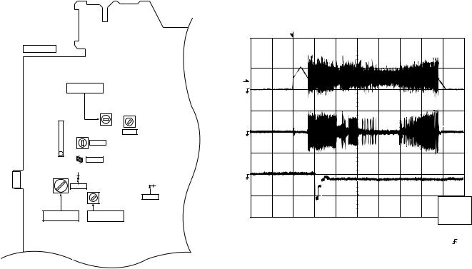
CD SECTION
•Adjustment
Since this CD system incorporates the following automatic adjustment functions, readjustment is not needed when replacing the pickup. Therefore, different PWBs and pickups can be combined freely.
Each time a disc is changed, these adjustments are performed automatically. Therefore, playback of each disc can be performed under optimum conditions.
Items adjusted automatically
(1)Offset adjustment (The offset voltage between the head amplifier output and the VREF reference voltage is compensated inside the IC.)
*Focus offset adjustment
*Tracking offset adjustment
(2)Tracking balance adjustment (waveform drawing Fig.15-2 EFBL)
(3)Gain adjustment (The gain is compensated inside the IC so that the loop gain at the gain crossover frequency will be 0 dB.)
*Focus gain adjustment
*Tracking gain adjustment
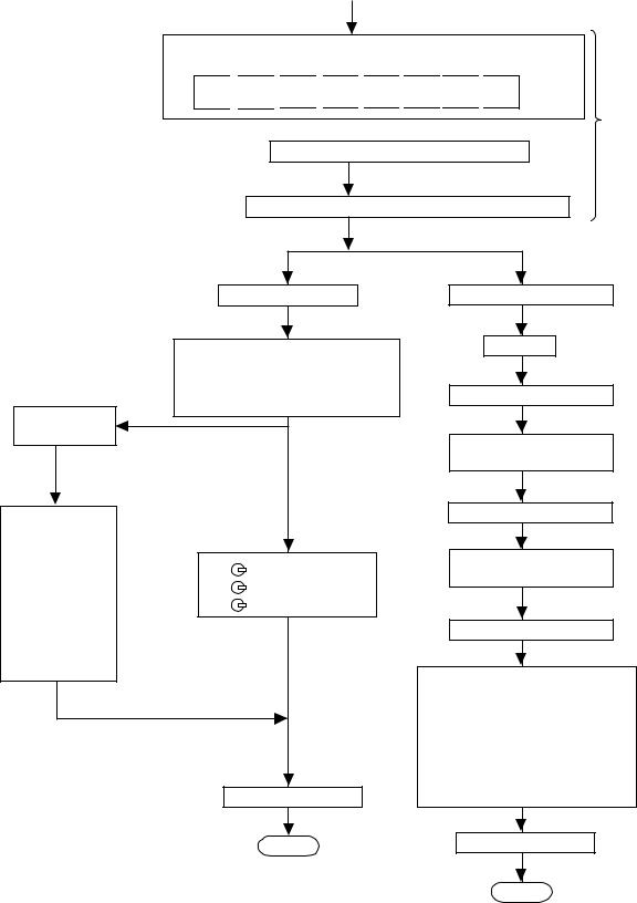
CD ERROR CODE DESCRIPTION
Error |
Explanation |
|
|
|
|
01 |
When Pickup set inner position, inner switch |
|
cannot detect 'ON' level for 10 secs. |
||
|
||
|
|
|
|
When tray moves to Open/Close, Open/Close switch |
|
10* |
cannot detect 'ON' level for 7 secs. |
|
When disc table rotate to target position. |
||
|
||
|
Clamp switch cannot detect 'ON' level for 7 secs. |
|
|
|
|
|
When disc table set to Disc1 position for 1 st time, |
|
11* |
"CLAMP SW", "DISC NO SW" and "OPEN/CLOSE" |
|
|
cannot detect 'ON' level for 14 secs. |
|
|
|
|
31 |
When it changes to CD function, DSP cannot read |
|
initial data. |
||
|
||
|
|
* 'CHECKING'
If Error is detected, 'CHECKING' will be display instead of 'ERCD**' display. 'ER-CD**' display will only be display when error had been detected for the 5 th times.
CNP301 AM/FM LOOP ANTENNA
|
|
|
|
Stopped |
|
T |
|
|
|
|
1999/04/05 |
20:26:47 |
|
|
|
|
|
|
|
|
|
|
|||
|
|
|
|
CH1=500 mV |
CH2=200 mV |
CH3=1 V |
|
500 ms/div |
||||
MAIN PWB |
|
|
|
DC |
10:1 |
|
DC |
10:1 |
DC 10:1 |
|
(500 ms/div) |
|
|
|
|
T |
|
|
|
|
|
|
|
|
|
FM BAND |
|
1 |
|
|
|
|
|
|
|
|
|
|
COVERAGE fL |
|
|
|
|
|
|
|
|
|
|
||
|
T301 |
T351 |
|
|
|
|
|
|
|
|
|
|
|
|
|
|
|
|
|
|
|
|
|
|
|
IC301 |
T302 |
AM IF |
3 |
|
|
|
|
|
|
|
|
|
|
|
|
|
|
|
|
|
|
|
|
||
FM IF |
|
|
|
|
|
|
|
|
|
|
|
|
1 |
|
|
|
|
|
|
|
|
|
|
|
|
|
FM RF |
|
|
|
|
|
|
|
|
|
|
|
L312 |
|
|
EFBL |
|
|
|
|
|
|
|
|
|
|
|
|
|
|
|
|
|
|
|
|
|
|
T303 |
R316 |
|
2 |
|
|
|
|
|
|
|
|
|
|
|
|
R356 |
|
|
|
|
|
|
|
|
|
TP301 T306 |
|
|
|
|
|
|
|
|
|
|
|
|
|
|
|
TP302 |
|
|
|
|
|
|
|
|
|
|
|
|
|
|
|
|
|
|
|
|
|
CH2 |
AM TRACKING |
AM BAND |
|
|
|
|
|
|
|
|
|
|
v/DIV |
|
|
|
|
|
|
|
|
|
|
200 mV |
||
fL |
COVERAGE fL |
|
|
|
|
|
|
|
|
|
|
|
|
|
|
|
=Filter= |
|
|
=Offset= |
=Record Length= |
=Trigger= |
|||
|
|
|
Smoothing : ON |
CH1 : |
0.000 V |
Main : |
100K |
Mode : SINGLE |
||||
|
|
|
BW |
: FULL |
|
CH2 : |
0.000 V |
Zoom : |
2k |
Type : EDGE CH1 |
||
|
|
|
|
|
|
CH3 : |
0.00 V |
|
|
Delay : |
0.0 ns |
|
|
|
|
|
|
|
CH4 : |
0.00 V |
|
|
Hold off : |
0.2 s |
|
|
|
|
|
|
|
|
|
Figure 15-2 |
|
|
||
Figure 15-1 ADJUSTMENT POINTS
– 15 –
CD-XP500/CD-XP5500
TEST MODE
∙ Setting the test mode
Any one of test mode can be set by pressing several keys as follows. <X-BASS> + <CD> + <POWER> TEST: CD operation test.
Function: -CD test mode. -Enter test mode.
C 
 D
D 


 T
T 
 E
E 
 S
S 
 T
T 

IL isn't done
OPEN/CLOSE operation is using manual.
<< >>, <<
 >> buttons make pick's slide possible.
<<PLAY>> key input.
Do TOC IL. Do normal play. When these following key is input into PLAY key, track number can be appoint directly.
<<MEMORY>> key input.
|
Adjustment result |
|
|
|
automatically will |
|
|
|
display as below. |
|
|
|
for each 2 sec : |
<< 1>> key: Track 4 |
|
|
a) "FOFF_XX" |
<< 2>> key: Track 9 |
|
|
b) "TOFF_XX" |
<< 3>> key: Track 15 |
|
|
c) "TBAL_XX" |
|
|
|
d) "TGAN_XX" |
|
|
|
f) "FGAN_XX" |
|
|
|
g) "RFLS_XX" |
|
|
explanation: |
|
|
|
a) |
Focus off set |
= "FOFF_XX" |
|
b) |
Tracking off set |
= "TOFF_XX" |
|
c) |
Tracking balance |
= "TBAL_XX" |
<<STOP>> key input. |
d) |
Tracking Gain |
= "TGAN_XX" |
|
f) |
Focus Gain |
= "FGAN_XX" |
|
g) |
RF level shift |
= "RFLS_XX" |
STOP |
<<MEMORY>> key input.
Laser ON.
<<MEMORY>> key input.
Tracking OFF play at that specific point.
<<MEMORY>> key input.
Tracking ON play from that specific point.
<<MEMORY>> key input.
Adjustment result automatically will display as below for each 2 sec :
a)"FOFF_XX"
b)"TOFF_XX"
c)"TBAL_XX"
d)"TGAN_XX"
f)"FGAN_XX"
g)"RFLS_XX"
<<STOP>> key input.
VOL — Last memory BAL — CENTER P.GEQ — FLAT X-BASS — OFF
To cancel : Power OFF
STOP
Sliding the PICKUP with << >>, <<
 >> button
must only be in STOP mode.
– 16 –
|
|
|
CD-XP500/CD-XP5500 |
|
Standard Specification of Stereo System Error Message Display Contents |
||||
|
|
|
|
|
|
Error Contents |
DISPLAY |
Notes |
|
|
|
|
|
|
TAPE |
Mechanism Error. |
'ER-TA**' |
00: Tape Mechanism Error. |
|
|
|
|
01: Initial Error. |
|
|
|
|
02: |
|
|
|
|
03: |
|
|
|
|
|
|
CD/VCD |
Pickup Mechanism Error. |
'ER-CD**' (*) |
01: PU-IN SW Detection NG. |
|
|
|
|
02: |
|
|
|
|
03: |
|
|
|
|
04: |
|
|
|
|
|
|
|
CD Changer Mechanism Error. |
'ER-CD**' |
10: Changer Error. |
|
|
|
|
11: Initial Error. |
|
|
|
|
12: |
|
|
|
|
13: |
|
|
|
|
|
|
|
CD DSP Communication Error |
'ER-CD**' |
31: DSP COMMUNICATION ERROR |
|
|
|
|
|
|
|
Focus Not Match. |
'NO DISC' |
|
|
|
|
|
|
|
|
IL Time Over. |
'NOT READ' |
|
|
|
|
|
|
|
TUN |
PLL Unlock. |
'ER-TU**' |
00: TUN Error. |
|
|
|
|
01: PLL Unlock. |
|
|
|
|
02: |
|
|
|
|
03: |
|
|
|
|
|
|
(*) CHECKING:
If CD changer mechanism error is detected, 'CHECKING' will be display instead of 'ER-CD**' display 'ER-CD**' will only be display when CD changer mechanism error had been detected for the 5 th times.
Speaker abnormal detection and +B PROTECTION display
In case speaker abnormal detection or +B PROTECTION had occured, it can be check by pressing 'POWER', 'VIDEO' and 'X- BASS' key twice. Display will show "S** B**". S is referring to speaker abnormal detection and B is referring to +B PROTECTION. ** is in hex valve.
+B PROTECTION is condition when irregular process occur on power supply line.
– 17 –
CD-XP500/CD-XP5500
NOTES ON SCHEMATIC DIAGRAM
∙Resistor:
To differentiate the units of resistors, such symbol as K and M are used: the symbol K means 1000 ohm and the symbol M means 1000 kohm and the resistor without any symbol is ohm-type resistor. Besides, the one with “Fusible” is a fuse type.
∙Capacitor:
To indicate the unit of capacitor, a symbol P is used: this symbol P means pico-farad and the unit of the capacitor without such a symbol is microfarad. As to electrolytic capacitor, the expression “capacitance/withstand voltage” is used.
(CH), (TH), (RH), (UJ): Temperature compensation (ML): Mylar type
(P.P.): Polypropylene type
∙Schematic diagram and Wiring Side of P.W.Board for this model are subject to change for improvement without prior notice.
∙The indicated voltage in each section is the one measured by Digital Multimeter between such a section and the chassis with no signal given.
1.In the tuner section, indicates AM indicates FM stereo
2.In the main section, a tape is being played back.
3.In the deck section, a tape is being played back. ( ) indicates the record state.
4.In the power section, a tape is being played back.
5.In the CD section, the CD is stopped.
∙Parts marked with “ 1 ” ( 


 ) are important for maintaining the safety of the set. Be sure to replace these parts with specified ones for maintaining the safety and performance of the set.
REF. NO |
DESCRIPTION |
POSITION |
|
|
|
JOG701 |
JOG VOLUME |
ON—OFF |
|
|
|
SW1 |
OPEN/CLOSE |
ON—OFF |
|
|
|
SW2 |
CLAMP |
ON—OFF |
|
|
|
SW3 |
DISC NUMBER |
ON—OFF |
|
|
|
SW4 |
PICKUP IN |
ON—OFF |
|
|
|
SW701 |
POWER |
ON—OFF |
|
|
|
SW702 |
FAST REWIND/PRESET DOWN |
ON—OFF |
|
|
|
SW703 |
FAST FORWARD/PRESET UP |
ON—OFF |
|
|
|
SW704 |
STOP |
ON—OFF |
|
|
|
SW705 |
PLAY/REPEAT |
ON—OFF |
|
|
|
SW711 |
CD |
ON—OFF |
|
|
|
SW712 |
TUNER (BAND) |
ON—OFF |
|
|
|
REF. NO |
DESCRIPTION |
POSITION |
|
|
|
SW713 |
TAPE |
ON—OFF |
|
|
|
SW714 |
VIDEO/AUX |
ON—OFF |
|
|
|
SW715 |
TIMER/SLEEP |
ON—OFF |
|
|
|
SW716 |
TUNING/TIME UP |
ON—OFF |
|
|
|
SW717 |
REC PAUSE |
ON—OFF |
|
|
|
SW718 |
MEMORY/SET |
ON—OFF |
|
|
|
SW719 |
TUNING/TIME DOWN |
ON—OFF |
|
|
|
SW720 |
CLOCK |
ON—OFF |
|
|
|
SW723 |
DISC SKIP |
ON—OFF |
|
|
|
SW724 |
OPEN/CLOSE |
ON—OFF |
|
|
|
SW725 |
EQUALIZER |
ON—OFF |
|
|
|
SW726 |
X-BASS/DEMO |
ON—OFF |
|
|
|
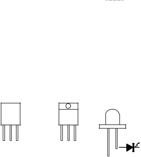
TYPES OF TRANSISTOR AND LED
FRONT |
FRONT |
FRONT |
VIEW |
VIEW |
|
|
|
VIEW |
E C B B C E
(S)(G) (D)
(1)(2) (3)
KRC102 M |
KTC3194 Y |
KTC2026 |
4204UYT7 |
KRC104 M |
KTC3199 GR |
|
A503BC2E |
KTA1266 GR |
KTC3200 GR |
|
SLR342VCJ |
KTA1273 Y |
KTC3203 Y |
|
|
KTA1274 Y |
|
|
|
– 18 –
|
|
|
TO MAIN SECTION |
|
TO DISPLAY SECTION |
|
|
|
|||||||||||
|
R-CH |
AGND |
L-CH |
DGND |
+5V (+B7) |
+5V (+B8) |
DGND (DRIVER) |
+6.5V (+B4) |
WRQ |
DRF |
CE |
DO |
DI |
CL |
CD RES |
CLAMP SW |
O/C |
DISC NO |
|
CNP7 |
1 |
2 |
3 |
4 |
5 |
6 |
7 |
8 |
1 |
2 |
3 |
4 |
5 |
6 |
7 |
8 |
9 |
10 |
CNP8 |
|
|
|
|
|
|
|
|
|
|
|
|||||||||
CD-XP500/CD-XP5500
|
SW2 |
SW3 |
|
|
DISC |
||
SW1 |
CLAMP |
||
NUMBER |
|||
OPEN/ |
|
M3 |
|
CLOSE |
|
T/T UP DOWN |
|
|
|
M LOADINGMOTOR |
+–
1 |
2 |
3 |
4 |
5 |
6 |
BI4 |
1 |
2 |
3 |
4 |
5 |
6 |
CNS4 |
1 |
2 |
3 |
4 |
5 |
6 |
CNP4 |
|
|
|
|
|
|
|
|
|
|
|
|
|
Q3 |
|
|
|
|
|
|
|
|
|
|
|
|
|
|
|
|
|
|
|
|
42 |
68 |
|
|
|
25 |
|
70 |
71 |
|
|
|
|
|
|
|
|
|
|
|
|
|
|
61 |
CE |
|
|
LCHO |
VDD5 |
|
|
|
|
CONT4 |
|
CONT3 |
CONT2 |
75 |
|
|
|
|
|
|
|
|
|
|
|
|
|
|
|
|
|
|
|
69 |
|
|
|
|
|
|
|
|
|
|
|||||||
|
|
|
|
|
|
|
|
|
|
|
|
|
|
|
|
|
|
|
|
|
||||||
|
|
62 |
CLK |
|
|
|
|
|
|
|
57 |
|
|
|
|
|
|
|
|
|
|
|||||
|
|
|
|
|
|
|
|
|
|
|
|
|
|
|
|
|
|
|
|
|
|
|
|
|
|
|
|
|
63 |
DI |
|
|
|
|
|
|
|
|
|
|
|
|
56 |
|
|
|
|
|
|
|
|
|
|
|
|
64 |
DO |
|
|
|
|
|
|
|
|
|
|
|
|
55 |
|
|
|
|
|
|
|
|
|
|
|
|
65 WRQ |
|
|
|
|
|
|
|
|
|
|
|
|
51 |
|
|
|
|
|
|
|
|
|
|
|
|
|
|
|
|
|
|
|
|
|
|
|
|
|
50 |
|
|
|
|
|
|
|
|
|
|
||
|
|
66 |
RES |
|
|
|
|
|
|
|
|
|
|
|
|
|
|
|
|
|
|
|
|
|
|
|
|
|
|
|
|
|
|
|
|
|
|
|
|
|
44 |
|
|
|
|
|
|
|
|
|
|
||
|
|
67 |
DRF |
|
|
|
|
|
IC1 |
|
|
|
|
|
|
|
|
|
|
|
|
|
|
|
|
|
|
|
|
|
|
|
|
|
|
|
|
|
|
43 |
|
|
|
|
|
|
|
|
|
|
|||
|
|
|
|
|
|
|
|
|
|
|
|
|
|
|
|
|
|
|
|
|
|
|
|
|
||
|
|
|
|
|
|
|
LC78645NE |
|
|
|
40 |
|
|
|
|
|
|
|
|
|
|
|||||
|
|
|
|
|
|
|
|
|
|
37 |
|
|
|
|
|
|
|
|
|
|
||||||
|
|
|
|
|
|
|
CD SERVO |
|
|
|
|
|
|
|
|
|
|
|
|
|
|
|||||
|
|
|
|
|
|
|
|
|
|
|
28 |
|
|
|
|
|
|
|
|
|
|
|||||
|
|
|
|
|
|
|
|
|
|
|
|
|
|
|
|
19 |
|
|
|
|
|
|
|
|
|
|
|
MHz |
48 |
XOUT |
|
|
|
|
|
|
|
|
|
|
|
|
|
1 |
2 |
17 |
25 |
41 42 |
|
38 39 |
|
|
|
XL1 |
|
|
|
|
|
|
|
|
|
|
|
|
|
CONT5 26 |
|
|
|
|
|
|
|
|
|
|
||
33.8688 |
|
|
|
|
|
|
|
|
|
|
|
|
|
|
|
|
|
|
|
|
|
|
|
|||
49 |
XIN |
|
|
|
|
|
|
|
|
|
|
|
SLDO 23 |
|
|
|
|
|
|
|
|
|
35 |
|||
ADAVDD |
|
|
|
|
|
|
|
|
|
|
SPDO 22 |
40 |
VCC4 |
|
|
|
|
|
|
|
||||||
|
|
|
RFVDD |
|
|
|
|
|
|
|
|
|
|
|
|
|
IC2 |
|
|
|
~ |
|||||
|
|
|
VDD XVDD |
VVDD |
LVDD |
RVDD |
|
|
|
|
|
|
FDO 21 |
|
|
|
|
|
|
|
|
|||||
|
|
|
FIN1 |
FIN2 |
TIN1 |
TIN2 |
LDS |
LDD |
|
|
|
|
|
|
|
|
29 |
|||||||||
|
|
|
|
|
|
|
|
|
|
|
|
|
||||||||||||||
|
|
|
TDO |
20 |
|
|
|
|
|
|
|
|
22 |
|||||||||||||
|
|
|
|
|
|
|
41 |
46 |
|
|
|
|
79 |
80 |
|
|
|
|
|
|
M63001FP |
|
|
|
||
|
|
|
5 |
18 38 47 77 |
7 |
8 |
9 |
10 |
|
+5V |
18 |
VCC1 |
FOCUS/TRACKING/ |
21 |
||||||||||||
|
|
|
|
|
|
|
|
|
|
|
|
|
|
|
|
|
24 |
VCC2 |
|
|
SPIN/SLED |
|
|
|
||
|
|
+3.3V |
|
|
|
|
|
|
|
|
|
|
|
|
|
|
23 |
|
|
|
|
|
14 |
|||
|
|
|
|
|
|
|
|
|
|
|
|
|
|
|
|
|
28 |
VCC3 |
|
|
|
DRIVER |
|
|
|
~ |
|
|
|
|
|
|
|
|
|
|
|
|
|
|
|
|
|
|
|
|
|
|
|
8 |
|||
|
|
|
|
|
|
|
|
|
|
|
|
|
|
|
|
|
|
|
|
|
|
|
|
|
|
|
+3.3V |
Q2 |
|
|
|
|
|
|
|
|
|
|
|
|
|
|
|
|
4 |
5 |
6 |
7 |
|
|
|
|
|
CONSTANT |
|
|
|
|
ZD1 |
|
|
|
|
|
|
|
LASER |
|
|
15 |
16 |
26 |
27 |
|
||||||
|
|
|
|
|
|
|
|
|
|
|
|
|
|
|
|
|
|
|
|
|
|
|||||
VOLTAGE |
|
|
|
|
|
3.3V |
|
|
|
|
|
|
|
DRIVER |
|
|
|
|
|
|
|
|
|
|
|
|
|
|
|
|
|
|
|
|
|
|
|
|
|
|
Q1 |
+3.3V |
|
|
|
|
|
|
|
|
|
|
|
+5V(+B7) |
|
|
|
|
|
|
|
|
|
|
|
|
|
|
|
|
|
|
|
|
|
|
|
|
|
|
PICKUP UNIT |
|
|
|
|
|
|
|
|
|
|
|
FOCUS COIL |
TRACKING COIL |
|
|
|
|
|
|
|
|
|
|
|
|
|
|
|
|
|
|
|
|
|
|
|
|
|
|
|
|
|
|
|
|
|
M1 |
|
+ |
|
|
|
|
|
|
|
|
|
|
|
|
|
|
|
|
|
|
|
|
|
|
|
SPINDLE |
M |
|
|
|
|
||
|
|
|
|
|
|
|
|
|
|
|
|
|
|
|
|
|
|
|
MOTOR |
|
|
|
|
|
||
|
|
|
|
|
|
|
|
|
|
|
|
|
|
|
|
|
|
|
|
|
|
– |
|
|
|
|
|
|
|
|
|
|
|
|
|
|
|
|
|
|
|
|
|
|
|
|
|
|
– |
|
|
|
SW4 |
|
|
|
|
|
|
|
|
|
|
|
|
|
|
|
|
|
|
|
|
M2 |
|
M |
|
|
|
|
|
|
|
|
|
|
|
|
|
|
|
|
|
|
|
|
|
|
|
|
|
|
|
|
PICKUP IN |
||
|
|
|
|
|
|
|
|
|
|
|
|
|
|
|
|
|
|
|
|
SLED |
|
|
|
|||
|
|
|
|
|
|
|
|
|
|
|
|
|
|
|
|
|
|
|
|
MOTOR |
+ |
|
|
|
|
|
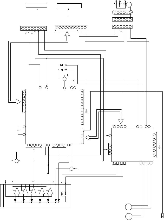
Figure 19 BLOCK DIAGRAM (1/3)
– 19 –
CD-XP500/CD-XP5500
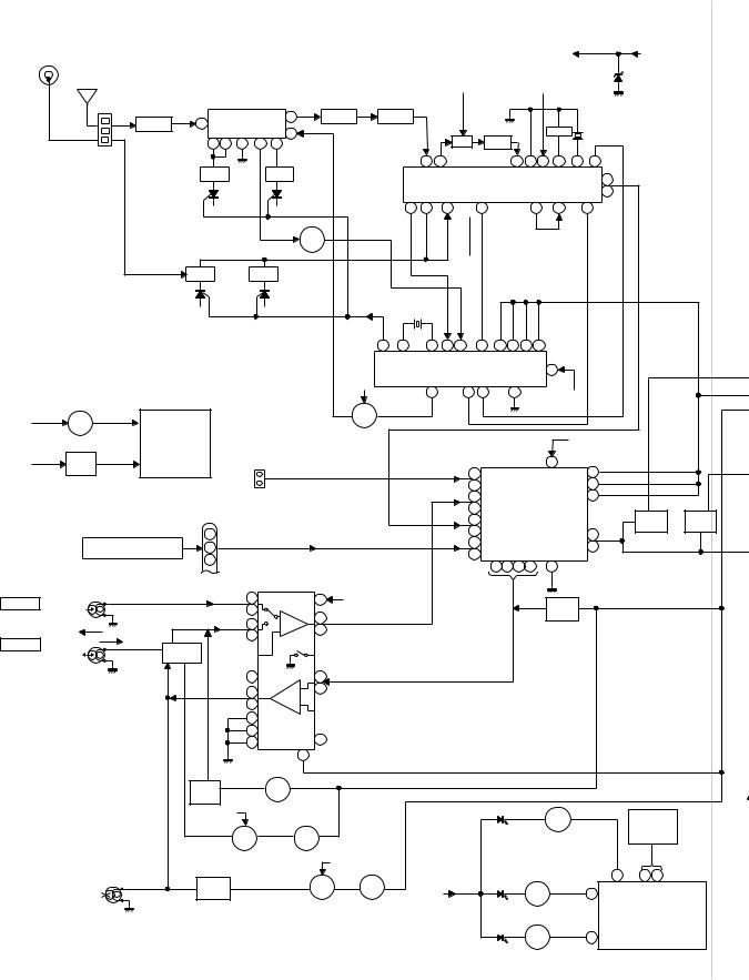
AM LOOP |
|
|
|
|
|
|
|
|
|
|
|
|
|
+B6 |
|
|
+B5 |
ANTENNA |
|
IC301 |
|
|
|
|
|
|
|
|
|
|
|||||
|
|
|
|
|
|
|
|
|
|
|
|
|
|||||
FM |
|
|
|
|
|
|
|
|
|
|
|
ZD351 |
|||||
ANTENNA |
TA7358AP |
|
|
|
|
+B6 |
|
+B6 |
|
5.1V |
|||||||
FM FRONT END |
FM IF |
|
|
|
|
|
|
|
10.7 MHz |
|
|||||||
BF301 |
1 |
|
|
|
6 |
T302 |
CF303 |
|
|
|
|
|
|
|
|
X351 |
|
|
|
|
9 |
|
|
|
|
|
450 kHz |
|
|
CF351 |
|
||||
B.P.F |
|
|
|
|
|
|
|
|
T351 |
|
|
|
456 kHz |
||||
3 |
4 |
5 |
7 |
|
|
|
|
CF352 |
|
|
|
|
|||||
CNP301 |
8 |
|
|
|
|
|
|
|
|
|
|
||||||
|
|
|
FM |
OSC |
|
|
1 |
2 |
AM IF |
4 |
5 |
9 |
8 |
17 13 |
|||
|
|
|
|
|
|
|
|||||||||||
|
|
|
|
|
OSC |
|
|
|
AMMIX |
|
AM IF |
FM/AMGND |
OUT FM+B |
MPXIN |
VCO |
FM/AM MO/ST |
|
FM RF |
L312 |
|
|
T301 |
|
|
|
|
|
|
|
|
FM DET |
|
|
L 14 |
|
|
|
|
|
|
FM |
|
|
|
|
|
|
|
|
|
|
|
R 15 |
|
AM TRACKING |
|
24 |
23 |
21 |
7 |
18 |
16 |
|
12 |
|
||||||
|
|
OSCAMOUT |
OSCAM IN |
RFAMIN |
STEREO |
LA1832S |
|
|
|
||||||||
|
|
|
|
|
OSC BUFF |
|
|
|
|
|
|
|
|
|
|
|
|
|
|
|
|
|
Q302 |
|
|
|
|
|
IC303 |
|
|
|
|
||
|
|
|
|
|
AM BAND |
|
|
|
|
|
FM IF DET. |
|
|
|
|||
T303 |
|
|
T306 COVERAGE |
|
|
|
|
FM MPX./ |
|
|
|
||||||
|
|
|
|
|
|
|
|
|
|
|
AM IF MPX. |
|
|
|
|||
|
|
|
|
|
|
|
|
|
|
|
VT |
X352 |
|
|
|
|
|
|
|
|
|
|
|
|
|
|
|
|
|
|
|
|
|
|
|
|
4.5 MHZ |
|
|
|
|
|
|
|
|
|
|
|
|
||
|
|
|
|
|
|
|
|
|
|
|
|
|
|
|
|
DI CLK |
|
|
|
|
|
|
|
||
|
|
|
|
|
|
|
IC302 |
|
|
|
|
|
|
|
|
CE |
DO |
|
|
|
|
|
|||
|
|
|
|
|
|
|
|
|
20 |
1 |
22 15 16 |
11 |
3 |
4 |
5 |
6 |
|
|
|
|
|
||||
|
|
|
|
|
|
|
LC72131 |
|
|
|
|
|
|
|
|||||||||||
|
|
|
|
|
|
|
|
|
|
|
OSC |
FM/AM |
MO/ST |
|
|
|
|
|
|
|
|
|
|||
|
|
|
|
|
|
PLL(TUNER) |
|
|
+B5 |
|
|
|
|
|
17 |
|
|
|
|
|
|||||
|
|
|
|
|
|
|
|
|
|
|
|
|
|
|
|
|
|
|
|
|
|||||
|
MOTOR |
|
|
|
|
|
|
|
|
|
|
7 |
9 10 |
|
21 |
|
|
|
|
|
|
|
|||
|
|
|
|
|
|
|
|
|
|
|
|
|
|
|
+B5 |
|
|
|
|
||||||
|
DRIVER |
|
|
|
|
|
|
FM+B |
|
Q360 FM |
|
|
|
|
|
|
|
|
|
|
|
|
|
||
+B3 |
Q706 |
|
|
|
|
|
|
|
|
|
|
|
|
|
|
|
|
|
|
|
|
||||
TAPE |
|
|
|
|
|
SWITCHING |
|
|
|
|
|
|
|
|
|
|
|
|
|
|
|||||
|
|
|
|
|
|
|
|
|
|
|
|
|
|
|
|
+B5 |
|
|
|
|
|||||
|
MECHANISM |
|
|
|
|
|
|
|
|
|
|
|
|
|
|
|
|
|
|
|
|
||||
|
|
JK690 |
|
|
|
|
|
|
|
|
|
|
|
|
|
|
|
|
|
|
|||||
|
Q707 |
ASS'Y |
|
|
|
|
|
|
|
|
|
|
|
|
|
|
|
|
|
|
|
|
|||
+B3 |
|
VIDEO/AUX |
|
|
|
|
|
|
|
|
|
|
|
|
23 |
|
|
|
|
|
|||||
|
|
|
|
|
|
|
|
|
|
|
|
|
|
|
|
|
|
|
|
||||||
Q708 |
|
|
|
|
|
|
|
|
|
L 9 |
|
|
|
|
DI 1 |
|
|
|
|
||||||
|
|
|
|
|
L |
AUX |
|
|
|
|
|
|
|
|
|
|
|
|
|
|
|
||||
|
|
|
|
|
|
|
|
|
|
|
|
|
|
|
|
|
|
|
|
|
|||||
|
SOLENOID |
|
|
|
|
R |
|
|
|
|
|
|
|
R 16 |
|
|
|
|
|
CE 2 |
|
|
|
|
|
|
DRIVER |
|
|
|
|
|
|
|
|
|
|
|
TAPE |
L 10 |
|
|
IC601 |
CLK 24 |
–20dB |
|
SYSTEM MUTE |
||||
|
|
|
|
|
1 |
|
|
|
|
|
|
|
|
|
Q604 |
||||||||||
|
|
|
|
|
|
|
|
|
|
|
|
|
R 14 |
AUDIO PROCESSOR 21 R |
|
Q602 |
|||||||||
|
|
|
|
BI601 |
|
|
|
|
|
|
|
|
R 15 |
|
LC75341 |
ATT |
Q601 |
Q603 |
|
||||||
|
|
|
|
|
|
|
|
|
|
TUNER |
L 11 |
|
|
||||||||||||
|
CNP7 |
|
|
|
2 |
|
|
|
|
|
|
|
CD |
L 12 |
|
|
|
|
|
4 L |
|
|
|
|
|
|
FROM CD SECTION |
|
|
3 |
|
|
|
|
|
|
|
|
R 13 |
|
7 8 1718 |
3 |
|
|
|
|
|
||||
|
|
|
|
|
|
|
|
|
|
|
|
|
|
|
|
|
|
|
|
|
|||||
|
|
|
|
|
|
|
|
|
|
|
|
|
|
|
|
|
|
|
|
|
|
||||
TAPE 1 |
L-CH |
|
|
|
L(T1) 1 |
|
13 |
|
+B5 |
|
|
|
|
|
|
|
|
Q107 |
|
REC/PLAY |
|
||||
|
|
|
R(T1) 24 |
|
P.B |
|
|
|
|
|
|
|
|
|
|
|
|
|
|||||||
P.B. HEAD |
R-CH |
|
|
|
|
L |
PB |
|
|
|
|
|
|
|
|
Q108 |
|
|
|
|
|||||
|
|
|
L(T2) 2 |
|
4 |
|
|
|
|
|
|
|
|
|
|
|
|
||||||||
|
REC. |
|
|
|
|
21 R |
|
|
|
|
|
|
|
|
|
|
MUTING |
|
|
|
|
||||
|
|
|
|
R(T2) 23 |
|
|
|
|
|
|
|
|
|
|
|
|
|
|
|
||||||
|
SWITCHING |
|
|
|
|
|
|
|
|
|
|
|
|
|
|
|
|
|
|||||||
TAPE 2 |
L-CH P.B. |
|
|
|
|
|
|
|
|
|
|
|
|
|
|
|
|
|
|
|
|||||
|
|
|
|
|
|
|
|
|
|
|
|
|
|
|
|
|
|
|
|
|
|||||
Q101~ |
|
|
|
|
|
|
|
|
|
|
|
|
|
|
|
|
|
|
|
|
|
||||
REC./P.B. |
R-CH |
Q104 |
|
|
|
|
|
|
|
|
|
|
|
|
|
|
|
|
|
|
|
|
|
|
|
HEAD |
|
|
|
|
POP REDUCE 6 T1/T2 |
H/N 7 |
L REC |
|
|
|
|
|
|
|
|
|
|
|
|
|
|
||||
|
AC BIAS |
|
|
|
|
|
|
|
|
|
|
|
|
|
|
|
|
|
|||||||
|
|
|
|
|
L REC 9 REC |
18 |
R |
|
IC101 |
|
|
|
|
|
|
|
|
|
|
|
|
|
|||
|
|
|
|
|
R REC 16 |
|
|
|
|
|
|
|
|
|
|
|
|
|
|
|
|
|
|||
|
|
|
|
|
|
11 |
|
|
|
|
AN7345K |
|
|
|
|
|
|
|
|
|
|
|
|
||
|
|
|
|
|
|
12 NOR/ |
T1/T2 10 ALC |
PLAYBACK AND RECORD |
|
|
|
|
|
||||||||||||
|
|
|
|
|
|
15 HIGH |
/PLAYBACK AMP. |
|
|
|
|
|
|
|
|
||||||||||
|
|
|
|
|
|
|
|
19 |
|
|
|
|
|
|
|
|
|
|
|
|
|
|
|
T1/T2 |
|
|
|
|
|
|
SWITCHING |
|
|
|
|
|
|
|
|
|
|
|
|
|
|
|
|
VF1 |
|||
|
|
|
|
|
|
|
|
|
|
|
|
|
|
|
|
|
|
|
|
|
|
||||
|
|
|
Q105 |
|
Q114 |
|
|
|
|
|
|
|
|
|
|
|
|
|
|
|
|
BIAS |
|||
|
|
|
Q106 |
SWITCHING |
|
|
|
|
|
|
|
|
|
|
|
|
|
|
|
|
|||||
|
|
|
|
|
+B5 |
|
|
|
|
|
|
|
|
|
|
|
|
|
|
JOG701 |
|
|
|||
|
|
|
|
|
|
|
|
|
|
|
|
|
|
|
|
|
|
|
Q701 |
|
|
|
|||
|
|
|
|
|
|
|
|
|
|
|
|
|
|
|
|
|
|
|
|
|
|
|
|||
|
|
|
|
|
|
|
|
|
|
|
|
|
|
|
|
LED706 |
|
|
|
|
JOG |
|
|
||
|
|
|
|
|
Q112 |
|
Q113 |
|
|
|
|
|
|
|
|
LED |
|
VOLUME |
|
|
|||||
|
|
|
|
|
|
|
|
|
|
|
|
|
|
|
|
|
|
|
|
||||||
|
|
|
|
|
|
SWITCHING |
|
|
|
|
|
|
|
|
|
|
|
DRIVER |
|
|
|
|
|||
|
|
|
|
|
|
+B5 |
|
|
|
|
|
|
|
|
LED |
|
|
|
|
|
|||||
|
|
|
|
|
|
|
|
|
|
|
|
|
|
|
|
|
|
|
|
|
|
||||
|
|
|
|
Q111 |
|
|
|
|
|
|
|
|
|
|
|
|
DRIVER |
|
68 |
49 50 |
|
|
|||
|
ERASE |
|
|
|
|
Q109 |
|
Q110 |
|
+B5 |
|
|
|
|
|
Q710 |
|
|
IC701 |
|
|
||||
|
|
|
L103 |
|
|
|
|
|
|
|
|
|
63 |
|
|
|
|||||||||
|
HEAD |
|
|
|
|
|
|
|
|
|
|
|
|
|
|
|
|
|
|||||||
|
|
|
BIAS |
|
SWITCHING |
|
BIAS |
|
|
|
|
LED703, |
|
|
IX0524AW |
|
|
||||||||
|
|
|
|
|
|
|
|
|
|
|
|
|
|
||||||||||||
|
|
|
|
OSC |
|
|
|
|
|
|
|
|
|
|
LED704 |
|
|
|
SYSTEM |
|
|
||||
|
|
|
|
|
|
|
|
|
|
|
|
|
|
|
|
|
|
|
|
|
MICROCOMPUTER |
|
|||
|
|
|
|
|
|
|
|
|
|
|
|
|
|
|
|
LED708 |
Q703 |
66 |
|
(2/2) |
|
|
|||
|
|
|
|
|
|
|
|
|
|
|
|
|
|
|
|
LED |
|
|
|
|
|
||||
|
|
|
|
|
|
|
|
|
|
|
|
|
|
|
|
|
|
|
|
|
|
|
|
||
|
|
|
|
|
|
|
|
|
|
|
|
|
|
|
|
|
|
DRIVER |
|
|
|
|
|
||
Figure 20 BLOCK DIAGRAM (2/3)
– 20 –
 Loading...