


CDE-44
CD-E500
CD-E55/E44
SERVICE MANUAL
No. S3333CDE500//
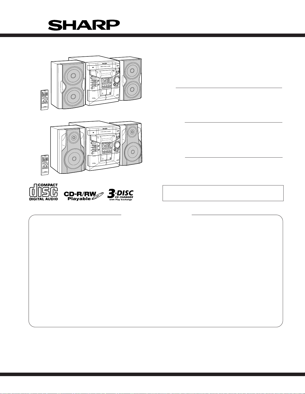
MINI COMPONENT SYSTEM
MODEL CD-E500
CD-E500 Mini Component System consisting of CD-E500
(main unit) and CP-E500 (speaker system).
Illustration CD-E500/E55
MODEL CD-E55
CD-E55 Mini Component System consisting of CD-E55 (main
unit) and CP-E55 (speaker system).
MODEL CD-E44
CD-E44 Mini Component System consisting of CD-E44 (main
unit) and CP-E44 (speaker system).
Illustration CD-E44
• In the interests of user-safety the set should be restored to its
original condition and only parts identical to those specified be
used.
CONTENTS
Page
IMPORTANT SERVICE NOTES (FOR U.S.A. ONLY)....................................................................................................... 2
SPECIFICATIONS ............................................................................................................................................................. 2
NAMES OF PARTS ........................................................................................................................................................... 3
DISASSEMBLY.................................................................................................................................................................. 5
REMOVING AND REINSTALLING THE MAIN PARTS..................................................................................................... 7
ADJUSTMENT ................................................................................................................................................................. 10
TEST MODE .................................................................................................................................................................... 11
NOTES ON SCHEMATIC DIAGRAM .............................................................................................................................. 15
TYPES OF TRANSISTOR AND LED............................................................................................................................... 15
BLOCK DIAGRAM ........................................................................................................................................................... 16
SCHEMATIC DIAGRAM / WIRING SIDE OF P.W.BOARD............................................................................................. 20
VOLTAGE ........................................................................................................................................................................ 38
WAVEFORMS OF CD CIRCUIT...................................................................................................................................... 39
TROUBLESHOOTING ..................................................................................................................................................... 40
FUNCTION TABLE OF IC................................................................................................................................................ 44
FL DISPLAY..................................................................................................................................................................... 50
REPLACEMENT PARTS LIST/EXPLODED VIEW
PACKING OF THE SET (FOR U.S.A. ONLY)
SHARP CORPORATION
This document has been published to be used
for after sales service only.
The contents are subject to change without notice.

CD-E500
CD-E55/E44
IMPORTANT SERVICE NOTES (FOR U.S.A. ONLY)
BEFORE RETURNING THE AUDIO PRODUCT
(Fire & Shock Hazard)
Before returning the audio product to the user, perform the
following safety checks.
1. Inspect all lead dress to make certain that leads are not
pinched or that hardware is not lodged between the chassis
and other metal parts in the audio product.
2. Inspect all protective devices such as insulating materials,
cabinet, terminal board, adjustment and compartment covers
or shields, mechanical insulators etc.
3. To be sure that no shock hazard exists, check for leakage
current in the following manner.
* Plug the AC line cord directly into a 120 volt AC outlet.
* Using two clip leads, connect a 1.5 kohm, 10 watt resistor
paralleled by a 0.15 µF capacitor in series with all exposed
metal cabinet parts and a known earth ground, such as
conduit or electrical ground connected to earth ground.
* Use a VTVM or VOM with 1000 ohm per volt, or higher,
sensitivity to measure the AC voltage drop across the
resistor (See diagram).
* Connect the resistor connection to all exposed metal parts
having a return path to the chassis (antenna, metal cabinet,
screw heads, knobs and control shafts, escutcheon, etc.)
and measure the AC voltage drop across the resistor.
VTVM
AC SCALE
1.5 kohms
10 W
0.15 µF
TO EXPOSED
TEST PROBE
METAL PARTS
CONNECT TO
KNOWN EARTH
GROUND
All check must be repeated with the AC line cord plug connection
reversed.
Any reading of 0.3 volt RMS (this corresponds to 0.2 milliamp.
AC.) or more is excessive and indicates a potential shock
hazard which must be corrected before returning the audio
product to the owner.
FOR A COMPLETE DESCRIPTION OF THE OPERATION OF THIS UNIT, PLEASE REFER
TO THE OPERATION MANUAL.
SPECIFICATIONS
■ General
Power source AC 120 V, 60 Hz
Power
consumption
Dimensions Width: 10-5/8" (270 mm)
Weight 14.5 lbs. (6.6 kg)
■ Amplifier (Except for Canada)
Output power 50 watts minimum RMS per channel into 8
Output terminals Speakers: 8 ohms
Input terminals Video/Auxiliary (audio signal): 500 mV/47 k
■ Amplifier
Output power RMS: 100 W (50 W + 50 W) (10 % T.H.D.)
Output terminals Speakers: 8 ohms
Input terminals Video/Auxiliary (audio signal): 500 mV/47 k
■ CD player
Type 3-disc multi-play compact disc player
Signal readout Non-contact, 3-beam semiconductor laser
D/A converter 1-bit D/A converter
Frequency
response
Dynamic range 90 dB (1 kHz)
Specifications for this model are subject to change without
prior notice.
96 W
Height: 12" (305 mm)
Depth: 13-1/2" (342 mm)
ohms from 100 Hz to 20 kHz, 10% total harmonic distortion
Headphones: 16 - 50 ohms (recommended:
32 ohms)
ohms
(For Canada)
Headphones: 16 - 50 ohms (recommended:
32 ohms)
ohms
pickup
20 - 20,000 Hz
■ Tuner
Frequency range FM: 87.5 - 108 MHz
AM: 530 - 1,720 kHz
■ Cassette deck
Frequency
response
Signal/noise ratio 50 dB (TAPE 1, playback)
Wow and flutter 0.3 % (WRMS)
■ Speaker
Type Twin-drive speaker system
Maximum input
power
Rated input power 50 W
Impedance 8 ohms
Dimensions Width: 7-7/8" (200 mm)
Weight 5.7 lbs. (2.6 kg)/each
■ Speaker
Type 2-way type speaker system
Maximum input
power
Rated input power 50 W
Impedance 8 ohms
Dimensions Width: 7-7/8" (200 mm)
Weight 7.0 lbs. (3.2 kg)/each
125 - 8,000 Hz (normal tape)
50 dB (TAPE 2, recording/playback)
(CD-E500/E55)
4" (10 cm) woofer 2
100 W
Height: 12" (305 mm)
Depth: 7-1/16" (180 mm)
(CD-E44)
2" (5 cm) tweeter
5" (13 cm) woofer
100 W
Height: 12" (305 mm)
Depth: 7-1/16" (180 mm)
– 2 –
10
11
CD-E500
CD-E55/E44
NAMES OF PARTS
■ Front panel
1.Disc Tray
1
2
3
4
5
6
7
8
9
12
13
14
15
16
17
18
19
22
23
2.Timer Set Indicator
3.Memory/Set Button
4.Power On/Stand-by Button
5.Clock Button
6.Timer/Sleep Button
7.Tuning and Time Up Button
8.Tuning and Time Down Button
9.Headphone Jack
10.Tape 2 Record Pause Button
11.Tape 1 Cassette Compartment
12.Equalizer Mode Select Button
13.Extra Bass/Demo Mode Button
14.Volume Up and Down Buttons
15.Disc Tray Open/Close Button
16.Disc Skip Button
17.Tape 2 Cassette Compartment
18.CD Button
19.Tape (1 2) Button
20.CD or Tape Stop Button
21.CD Track Down or Fast Reverse, Tape 2 Rewind,
Tuner Preset Down Button
22.Tuner (Band) Button
23.Video/Auxiliary Button
24.CD Play or Repeat, Tape Play Button
25.CD Track Up or Fast Forward, Tape 2 Fast Forward,
Tuner Preset Up Button
20
21
CD-E500/E55
24
25
213 4567
131210 11
1
2
3
8
9
4
5
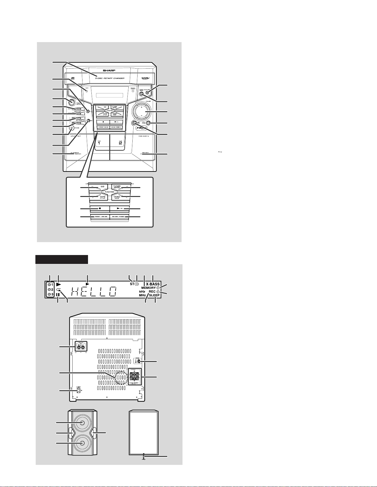
■ Display
1.Disc Number Indicators
2.CD Play Indicator
3.Tape Play Indicator
4.FM Stereo Mode Indicator
5.FM Stereo Receiving Indicator
6.Memory Indicator
7.Extra Bass Indicator
8.Timer Recording Indicator
9.Timer Play Indicator
10.CD Pause Indicator
11.CD Repeat Play Indicator
12.Tape Record Indicator
13.Sleep Indicator
■ Rear panel
1.Video/Auxiliary (Audio Signal) Input Jacks
2.Cooling Fan
3.AC Power Input Jack
4.FM/AM Loop Antenna Jack
5.Speaker Terminals
Note:
This product is equipped with a cooling fan inside, which begins to
run at a specified volume level for better heat radiation.
■ Speaker system
1
2
2
1.Woofers
2.Bass Reflex Ducts
3.Speaker Wire
1
3
– 3 –
CD-E500
CD-E55/E44
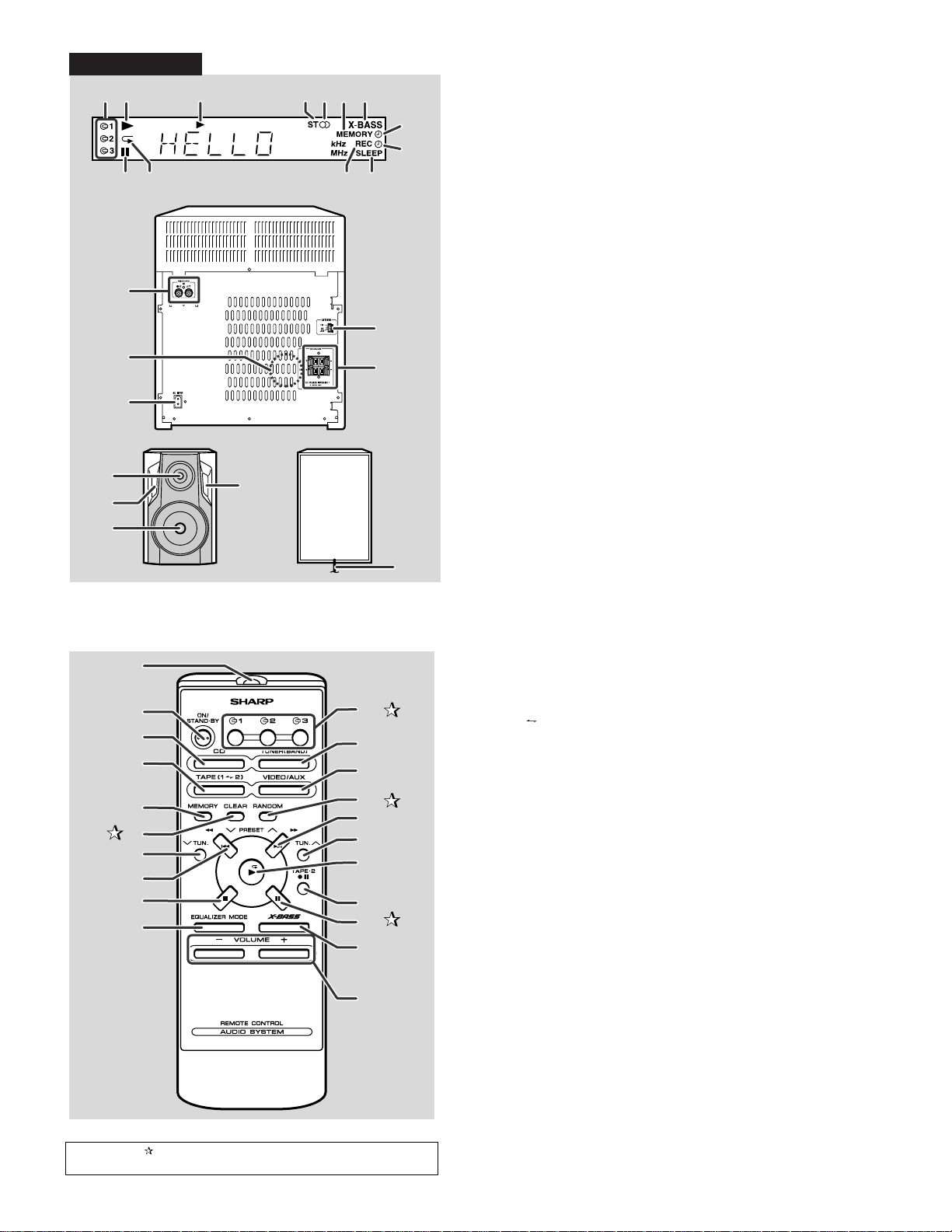
CD-E44
213 4567
131210 11
■ Displa y
1.Disc Number Indicators
2.CD Play Indicator
8
9
3.Tape Play Indicator
4.FM Stereo Mode Indicator
5.FM Stereo Receiving Indicator
6.Memory Indicator
7.Extra Bass Indicator
8.Timer Recording Indicator
9.Timer Play Indicator
10.CD Pause Indicator
11.CD Repeat Play Indicator
12.Tape Record Indicator
13.Sleep Indicator
1
4
2
5
3
■ Rear panel
1.Video/Auxiliary (Audio Signal) Input Jacks
2.Cooling Fan
3.AC Power Input Jack
4.FM/AM Loop Antenna Jack
5.Speaker Terminals
Note:
This product is equipped with a cooling fan inside, which begins to
run at a specified volume level for better heat radiation.
■ Speaker system
1
2
2
1.Tweeter
2.Bass Reflex Ducts
3.Woofer
4.Speaker Wire
3
4
■ Remote control
1
1.Remote Control Transmitter
2.Power On/Stand-by Button
3.CD Button
4.Tape (1 2) Button
5.Memory Button
6.Program Clear Button
7.Tuning and Time Down Button
8.CD Track Down or Fast Reverse, Tape 2 Rewind,
Tuner Preset Down Button
9.CD or Tape Stop Button
10.Equalizer Mode Select Button
11.Disc Number Select Buttons
12.Tuner (Band) Button
13.Video/Auxiliary But to n
14.CD Random Button
15.CD Track Up or Fast Forward, Tape 2 Fast Forward,
Tuner Preset Up Button
16.Tuning and Time Up Button
17.CD Play or Repeat, Tape Play Button
18.Tape 2 Record Pause Button
19.CD Pause Button
20.Extra Bass Button
21.Volume Up and Down Buttons
10
2
3
4
5
6
7
11
12
13
14
15
16
17
8
9
18
19
20
21
Buttons with " " mark in the illustration or highlighted in bold on the
right can be operated on the remote control only.
– 4 –
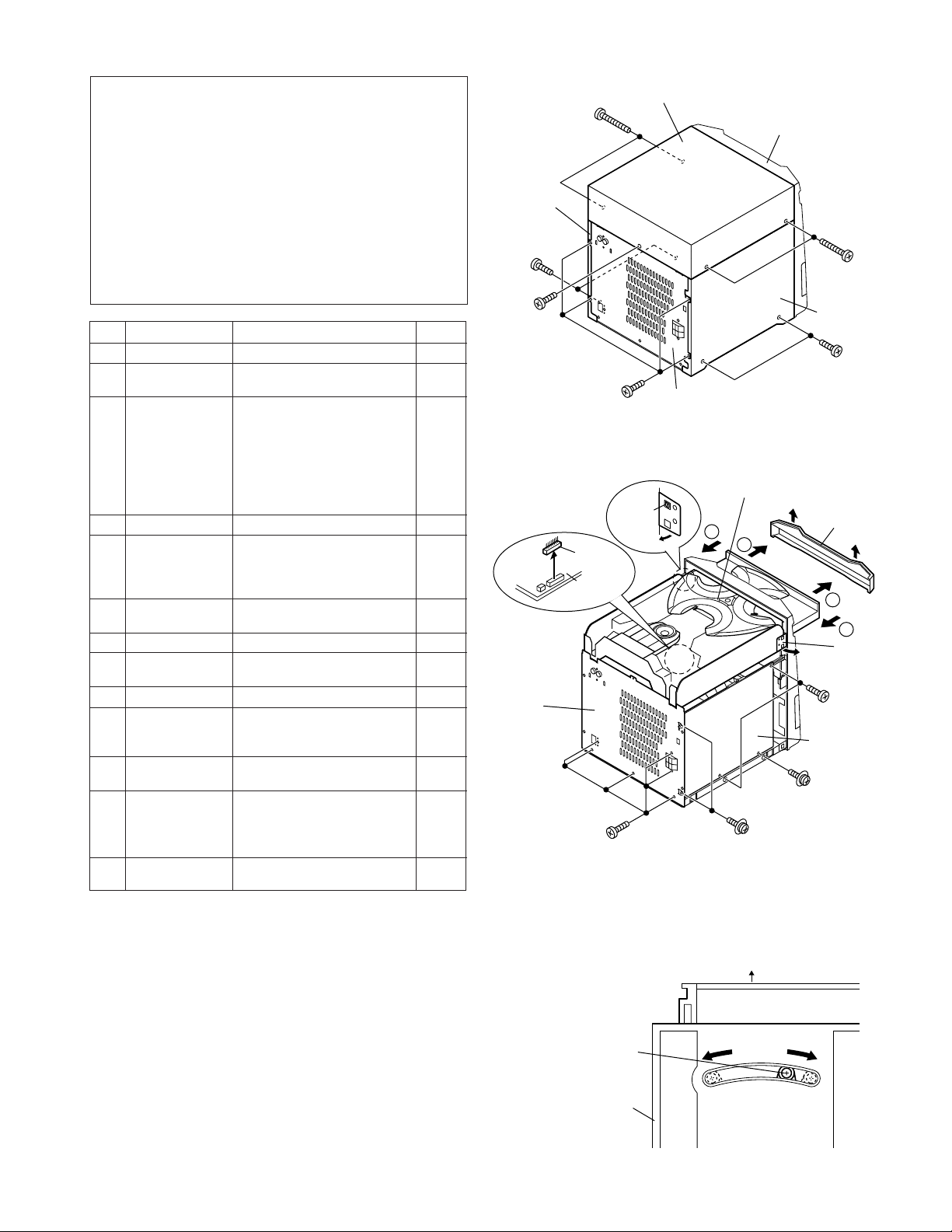
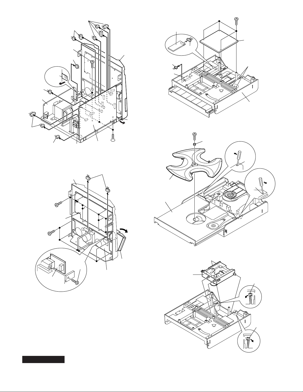
DISASSEMBLY
Caution on Disassembly
Follow the below-mentioned notes when disassembling
the unit and reassembling it, to keep it safe and ensure
excellent performance:
1. Take cassette tape and compact disc out of the unit.
2. Be sure to remove the power supply plug from the wall
outlet before starting to disassemble the unit.
3. Take off nylon bands or wire holders where they need to
be removed when disassembling the unit. After servicing
the unit, be sure to rearrange the leads where they were
before disassembling.
4. Take sufficient care on static electricity of integrated
circuits and other circuits when servicing.
STEP
10 CD Servo PWB 1. Screw ...................... (K1) x4 6-3
11 Turntable 1. Screw ....................... (L1) x1 6-4
12 Loading Tray 1.
13 CD Mechanism 1. Hook ........................ (N1) x2 6-5
Note 1: How to open the changer manually. (Fig. 5-3)
1. In this state, turn fully the loading Gear in the arrow direction
2. After that,push foward the loading tray.
Note 2:
1. After removing the connector for the optical pickup from the
REMOVAL
1 Top Cabinet 1. Screw ...................... (A1) x5 5-1
2 Side Panel 1. Screw ...................... (B1) x8 5-1
(Left/Right)
3 CD Player Unit 1. Turn on the power supply,.. 5-2
4 Rear Panel 1. Screw ...................... (D1) x8 5-2
5 Main PWB 1. Screw ...................... (E1) x3 5-2
6 Front Panel 1. Screw .......................(F1) x3 6-1
7 Display PWB 1. Screw .................... (G1) x13 6-2
8 Tape Mechanism 1. Open the cassette holder. 6-2
9
Headphones PWB
(Note 2) 2. Socket ..................... (K2) x2
Block
through the hold on the loading tray bottom.
connector, wrap the conductive aluminium foil around the front end
of the connector so as to protect the optical pickup from electrostatic damage.
open the disc tray, take out
the CD tray cover, and close.
2. CD Tray Cover........ (C1) x1
3. Hook........................ (C2) x2
4. Socket ..................... (C3) x1
5. Socket ..................... (C4) x2 6-1
2. Screw ...................... (E2) x2 6-1
3. Socket ..................... (E3) x9
4. Socket ..................... (E4) x2 6-2
2. Hook.........................(F2) x2
2. Screw...................... (H1) x8
1. Screw ....................... (J1) x1 6-2
3. Solder...................... (K3) x2
2. Spacer......................(L2) x1
2.
PROCEDURE
.................................. (Note 1)
Push forward the loading tray.
Inserting the flat head into the
hole, push in the direction indicated by the arrow. ...
(M1) x2
FIGURE
6-4
Side Panel
(Right)
(B1)x2
ø3x8mm
(A1)x1
ø3x8mm
Rear
Panel
Loading Gear
(A1)x2
ø3x16mm
(B1)x4
ø3x10mm
(C3)x1
CD Servo
PWB
(D1)x6
ø3x8mm
Top Cabinet
(C2)x1
Pull
Rear Panel
Figure 5-1
CD Player Unit
2
(D1)x2
ø3x10mm
Figure 5-2
1
Front Side
or
CD-E500
CD-E55/E44
Front
Panel
(A1)x2
ø3x16mm
Side Panel
(Left)
(B1)x2
ø3x8mm
CD Tray Cover
(C1)x1
1
2
(C2)x1
Pull
(E1)x2
ø3x6mm
Main
PWB
(E1)x1
ø3x10mm
– 5 –
CD Player Unit
(Bottom View)
Figure 5-3
CD-E500
CD-E55/E44
(F2)x1
(E3)x1
Power PWB
(E3)x2
(E3)x1
(C4)x2
(E2)x2
ø3x6mm
(E3)x1
Fan Motor
PWB
(E3)x4
Figure 6-1
Main PWB
Front Panel
(F2)x1
(F1)x3
ø3x8mm
T/T Motor PWB
(K2)x1
Switch PWB
(K2)x1
(L1)x1
ø3x10mm
(K1)x4
ø3x8mm
CD Servo
PWB
Solder
(K3)x2
CD Player Unit
Figure 6-3
(L2)x1
Screwdriver
(M1)x1
(G1)x13
ø2.5x10mm
Display PWB
(H1)x8
ø3x8mm
Headphones
PWB
Holder
PWB
Front Panel
(J1)x1
ø2.5x10mm
Figure 6-2
(E4)x2
Tape
Mechanism
Open
Cassette
Holder
Turntable
Loading Tray
CD
Mechanism
Block
Screwdriver
(M1)x1
Figure 6-4
Hook
(N1)x1
Pull
CP-E500/E55/E44
These speakers CP-E500,CP-E55,CP-E44 are available in
assembles only and may not be disassembled.
Hook
(N1)x1
Pull
Figure 6-5
– 6 –
REMOVING AND REINSTALLING THE MAIN PARTS
TAPE MECHANISM SECTION
Perform steps 1 to 6 and 8 of the disassembly method to
remove the tape mechanism.
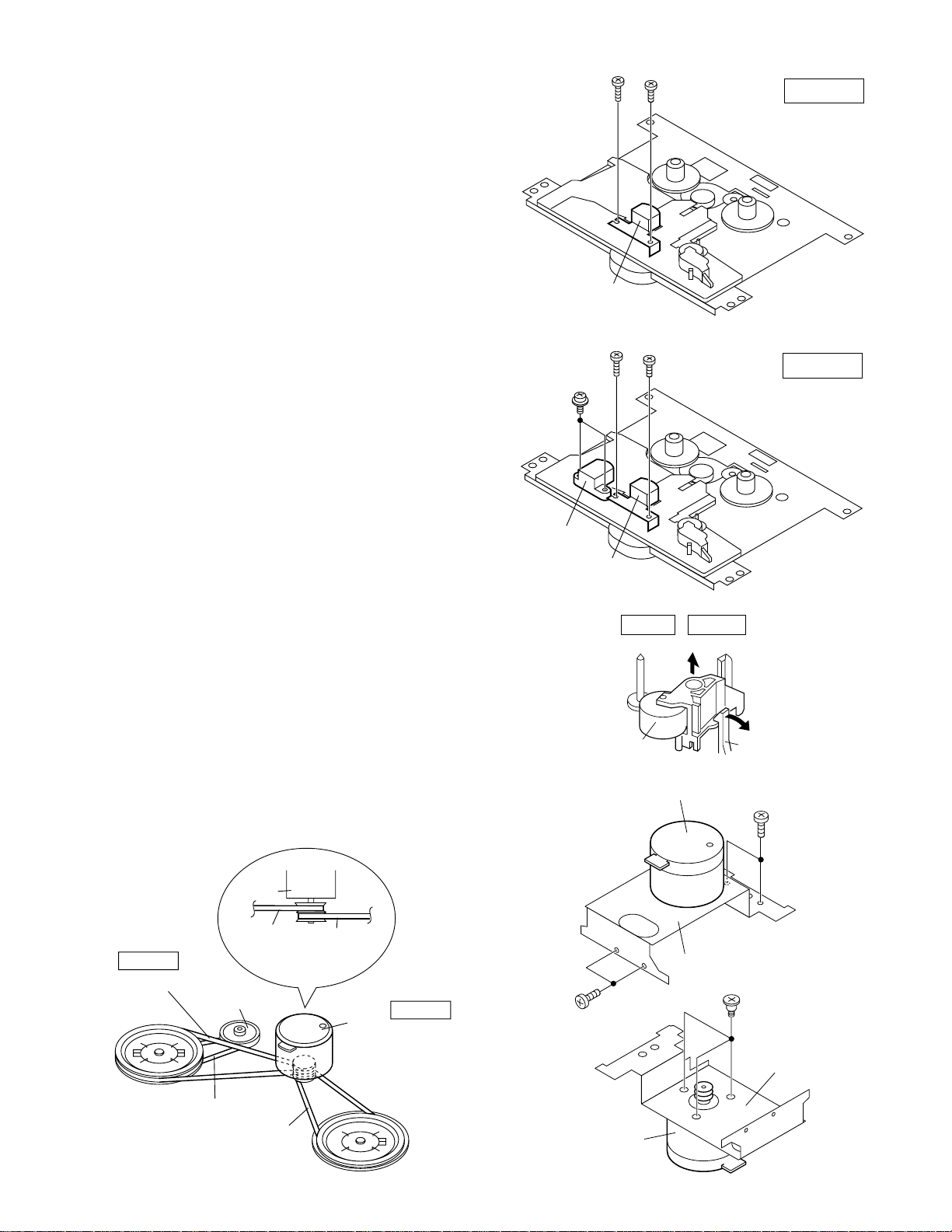
How to remove the record/playback and erase
heads (TAPE 1) (See Fig. 7-1)
1. When you remove the screws (A1) x 2 pcs., the record/
playback head can be removed.
How to remove the playback head (TAPE 2)
(See Fig. 7-2)
1. When you remove the screws (B1) x 2 pcs., the erase head
can be removed.
2. When you remove the screws (B2) x 2 pcs., the record/
playback head can be removed.
Note:
After replacing the heads and performing the azimuth
adjustment, be sure to apply screwlock.
(A1)x1
ø2x7mm
Record/
Playback Head
(B2)x1
ø2x7mm
(A1)x1
ø2x3mm
Figure 7-1
(B2)x1
ø2x3mm
CD-E500
CD-E55/E44
TAPE 1
TAPE 2
How to remove the pinch roller (TAPE 1,2)
(See Fig. 7-3)
1. When you remove the screw (C1) x 1 pc., the pinch roller
can be removed.
Note:
When installing the pinch roller, pay attention to the spring
mounting position.
How to remove the motor (See Fig. 7-4)
1. Remove the belt.
2. Remove the screws (D1) x 4 pcs., to remove the motor
bracket.
3. Remove the screws (D2) x 3 pcs., to remove the motor.
How to remove the belt (TAPE 1)
(See Fig. 7-5)
1. Remove the main belt (F1) x 1 pc., from the motor side.
How to remove the belt (TAPE 2)
(See Fig. 7-5)
1. Remove the main belt (G1) x 1 pc., from the motor side.
2. Remove the FF/REW belt (G2) x 1 pc.
(B1)x2
ø2x8mm
Erase Head
Record/
Playback Head
Figure 7-2
TAPE 1 TAPE 2
Pinch Roller
(C1)x1
Figure 7-3
Motor
<A>
Pinch Roller
Pawl
(D1)x2
ø2x4mm
TAPE 2
Main
Belt
(G1)x1
REW/FF
Clutch Ass'y
REW/FF
Belt
(G2)x1
Motor
TAPE 2
Main Belt
(G1)x1
Main
Belt
(F1)x1
TAPE 1
Main Belt
(F1)x1
Motor
TAPE 1
– 7 –
(D1)x2
ø2x4mm
Motor
Bracket
(D1)x3
Special Screw
Motor
Bracket
Motor
Figure 7-4Figure 7-5
CD-E500
CD-E55/E44
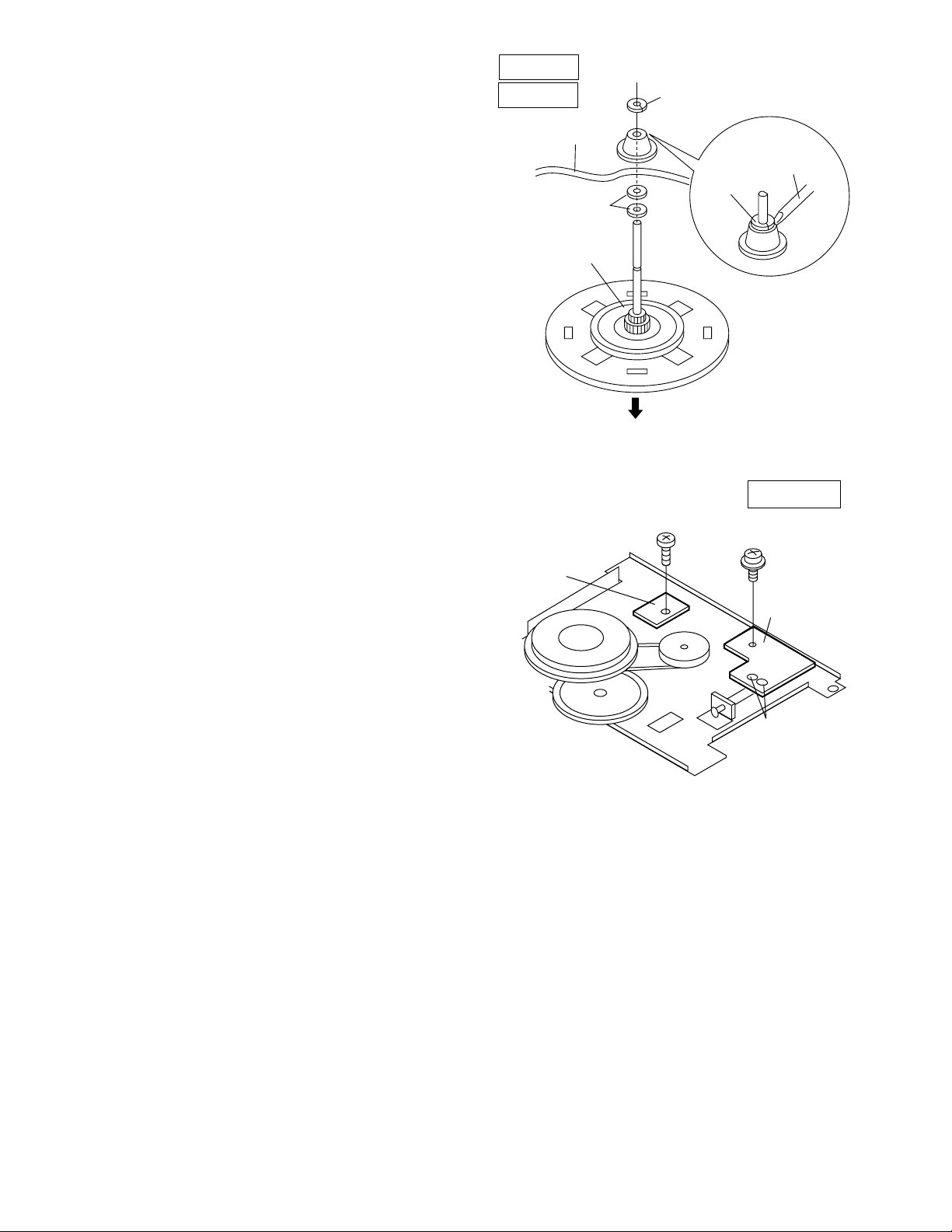
How to remove the flywheel (TAPE 1,2)
(See Fig. 8-1.)
1. Remove the stop washer (H1) x 1 pc., with a small precision
screwdriver to extract the flywheel from the capstan metal.
Note:
When the stop washer is deformed or damaged, replace it
with a new one.
How to reinstall the parts
Install each part in the reverse order of the removal with care.
TAPE 1
TAPE 2
Mechanism
Chassis
Washerx2
Flywheel
(H1)x1
Stop Washer
Figure 8-1
Stop
Washer
Driver
How to remove the tape mechanism PWB
(TAPE 1,2) (See Fig. 8-2.)
1. Remove the screw (J1) x 1 pc., to remove the tape
mechanism PWB.
2. Remove the screw (J2) x 1 pc.
3. Remove the solder joints (J3) x 2 pcs., to remove the tape
mechanism PWB.
Tape
Mechanism
PWB
(J1)x1
ø2x3mm
Figure 8-2
TAPE 1,2
(J2)x1
ø2x8mm
Tape
Mechanism
PWB
(J3)x2
Solder
Joint
– 8 –
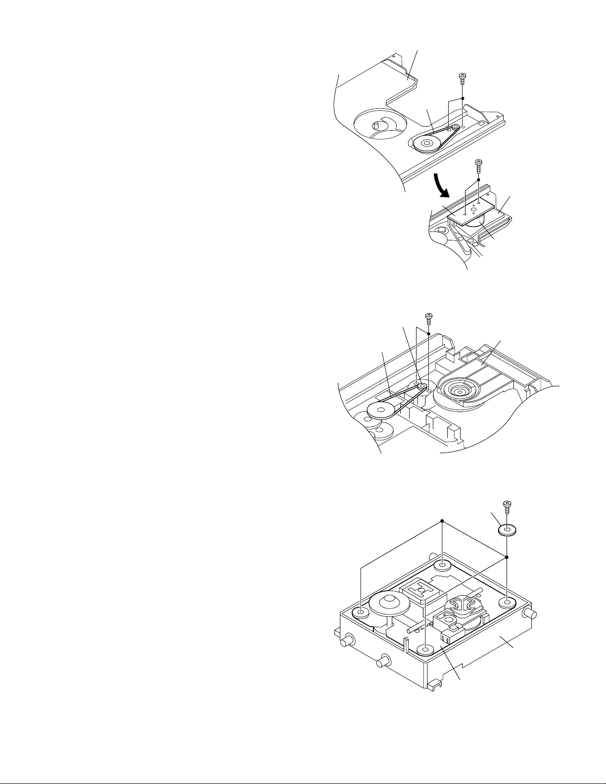
CD PLAYER SECTION
(B1)x2
ø2.4x5mm
Up/Down Loading Motor
CD Player Unit
(B2)x1
Perform steps 1, 2, 3, 10,11, and 12 of the disassembly
method to remove the CD mechanism.
How to remove the T/T rotate motor
(See Figs. 9-1)
1. Remove the screws (A1) x 2 pcs.
2. Remove the belt (A2) x 1 pc.
3. Remove the screws (A3) x 2 pcs., to remove the T/T rotate
motor.
How to remove the up/down loading motor
(See Figs. 9-2)
1. Remove the screws (B1) x 2 pcs.
2. Remove the belt (B2) x 1 pc.
Loading Tray
(A2)x1
T/T Motor PWB
Figure 9-1
(A1)x2
ø2.4x3mm
CD-E500
CD-E55/E44
(A3)x2
ø3x10mm
Loading Tray
(Bottom View)
T/T Rotate Motor
How to remove the CD mechanism unit
(See Fig. 9-3)
Perform steps 1, 2, 3, 10and 13 of the disassembly method to
remove the CD mechanism.
1. Remove the screws (C1) x 4 pcs., to remove the mechanism
unit.
Note
After removing the connector for the optical pickup from the
connector wrap the conductive aluminium foil around the front
end of connector so as to protect the optical pickup from
electrostatic damage.
Figure 9-2
Figure 9-3
Holder
PWB
CD Mechanism Unit
(C1)x4
ø2.5x10mm
Holder
– 9 –
CD-E500
CD-E55/E44
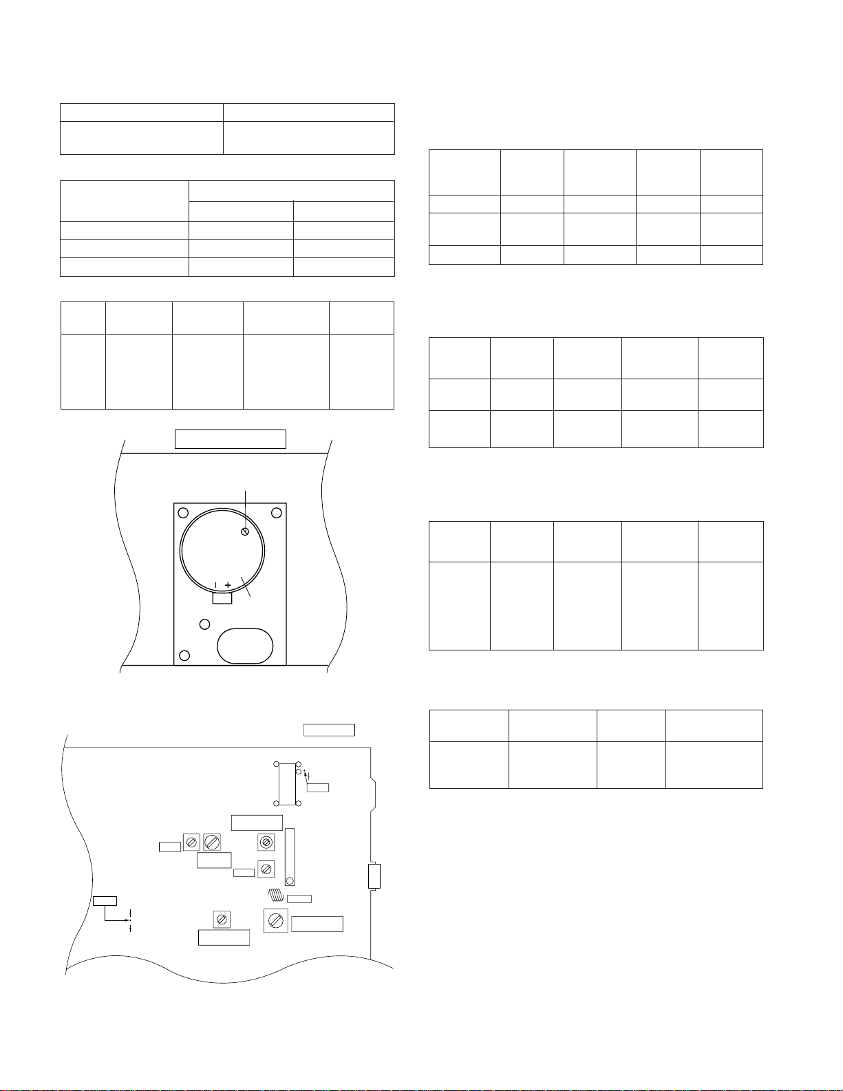
ADJUSTMENT
MECHANISM SECTION
••
• Driving Force Check
••
Torque Meter Specified Value
Play: DM-300 Tape 1: Over 80 g
••
• Torque Check
••
Torque Meter
Play: DM-300 10 to 20 g.cm 10 to 20 g.cm
Fast forward: DM-300 — Over 50 g.cm
Rewind: DM-300 — Over 50 g.cm
••
• Tape Speed
••
Test Tape
Adjusting
Tape TCC-119 Variable 3,000 ± 30 Hz Speaker
speed Resistor in Terminal
motor. (Load
TAPE MECHANISM
Variable Resistor in Motor
T351
AM IF
TP302
R356
R357
Tape 2: Over 80 g
Tape 1
Point
Tape
Motor
Figure 10-1
L303
FM BAND
COVERAGE fL
VR351
FM MUTE
Level
T304
FM IF
T306
AM BAND
COVERAGE fL
Specified Value
Specified
Value
MAIN PWB
1
22
20
R381
TP301
IC302
11 12
IC301
1
L302
FM RF
T302
AM TRACKING
fL
Tape 2
Instrument
Connection
resistance:
8 ohms)
CNP301
TUNER SECTION
fL: Low-range frequency
fH: High-range frequency
••
•
AM IF/RF
••
Signal generator: 400 Hz, 30%, AM modulated
Test Stage
AM IF 450 kHz 1,720 kHz T351 *1
AM Band — 530 kHz (fL): T306 *2
Coverage 1.1 ± 0.1 V
AM Tracking 990 kHz 990 kHz (fL): T302 *1
*1. Input: Antenna Output: TP302
*2. Input: Antenna Output: TP301
••
• FM RF
••
Signal generator: 1 kHz, 40 kHz dev., FM modulated
Test Stage
FM Band — 87.50 MHz L303 (fL): *1
Coverage 1.3 V ± 0.1 V
FM RF 98.00 MHz 98.00 MHz L302 *2
*1. Input: Antenna Output: TP301
*2. Input: Antenna Output: Speaker Terminal
••
• FM IF
••
Signal generator: 10.7 MHz, FM modulated
Test Stage
IF 10.7 MHz 98 MHz T304 *1
*1. Input: Antenna Output: TP301
• FM Mute Level (FM ST MODE)
Signal generator: 1 kHz, 40 kHz dev., FM modulated
Frequency
98.00 MHz 98.00 MHz VR351*1 Input:CNP301
(26 dBµV) Output: Speaker
*1. Adjust so that an output signal appears.
Frequency Frequency
Display
Frequency Frequency
Display
(10-30 dB)
Frequency Frequency
Display
Display
Adjusting
Setting/
Adjusting
Point
Setting/
Adjusting
Point
(Turn the
core of transformer T304
fully counterclock wise)
Adjusting
Parts
Setting/
Parts
Terminal
Instrument
Connection
Instrument
Connection
Instrument
Connection
Instrument
Connection
Figure 10-2 ADJUSTMENT POINTS
– 10 –
TEST MODE
The test mode applied to this microcomputer has three modes,
namely the ordinary test mode for adjustment or measurement,
the aging test mode, and the self-diagnosis test mode for selfjudgment in case of final product inspection.
1. Turning on the test mode
For obtaining each test mode, press the POWER ON/
STAND BY button, while keeping pressing the following
two buttons in the ordinary stand-by mode (power off ). In
this case, the main unit buttons are valid. When turning the
POWER on with remote control buttons, test modes are not
obtained.
[Ordinary test mode]
1. CD Test Mode (TEST 1) ..........................................
CD + VOLUME UP
2. Tuner Test Mode (TEST 2)......................................
TUNER(BAND) + VOLUME UP
3. Electronic Volume Test Mode (TEST 3) ..................
TUNING DOWN + VOLUME UP
4. Timer Test Mode (TEST 4) ......................................
TIMER/SLEEP + VOLUME DOWN
5. FL Test Mode (TEST 5) ...........................................
CLOCK + VOLUME DOWN
6. CD MECHANISM Aging Test Mode (TEST 8) ........
MEMORY/SET + VOLUME DOWN
CD-E500
CD-E55/E44
Press the following buttons in this state to obtain the
operations specified below.
"POWER ON/STAND BY" ..
"FF/FWD".................After the pickup returns to the
"REW/REV"..............After the pickup returns to the
"MEMORY/SET" ......Shift to step 2
"STOP".....................Invalid
"VIDEO/AUX"...........CLV
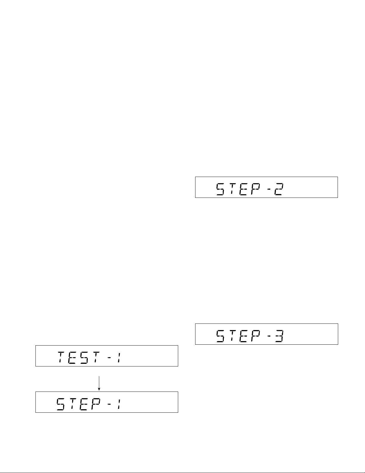
2. Step 2 Mode
Press the "MEMORY/SET" button in this mode to transmit
the laser lighting command LDON (8400) and turn on the
laser. Any other operations are not performed in this case.
Test mode and power turned off to
shift to the ordinary standby mode.
innermost periphery, it slides toward
the outer periphery while this button
is pressed.
innermost periphery, it slides toward
the inner periphery while this button
is pressed. If PICKUP IN is on, input
is invalid.
[Self-diagnosis Test Mode]
1. Button input diagnosis test mode (TEST06) .…....
TUNNIG UP + VOLUME UP
Processes are different depending on destinations at initial
settings.
2. CD Test Mode (TEST 1)
In the CD test mode the operation of each step is possible
even if the LID-SW is off. If focus cannot be taken in step
3 or any error is processed, it is impossible to proceed to
the next step. During error processing, end the test mode
by pressing the POWER ON/STAND BY button or return to
the step 1 by pressing the CD STOP button. Any other
operations are inhibited.
1. Step 1 Mode
When the CD test mode is obtained, the following display
lights up. Then CD initialization operation flow proceeds
up to CD STB off to wait for the following buttons to be
pressed.
One second after display lights up
Press the following buttons in this state to obtain the
operations specified below.
"POWER ON/STAND BY" .
"FF/FWD" ................ The pickup slides toward the outer
"REW/REV" ............. The pickup slides toward the inner
"MEMORY/SET"......Shift to step 3
3. Step 3 Mode
While the laser keeps lighting, CD initialization operation
flow proceeds up to 'CLV servo ON' to wait for the
following buttons to be pressed.(Focus servo turned on
for focus search)
The focus search is repeated to take focus.
Press the following buttons in this state to obtain the
operations specified below.
"POWER ON/STAND BY" .
"FF/FWD" ................ The pickup slides toward the outer
"REW/REV" ............. The pickup slides toward the inner
"MEMORY/SET"......If focus has been taken, shift to step 4
Test mode and power turned off to
shift to the ordinary standby mode.
periphery while this button is pressed.
periphery while this button is pressed.
If PICKUP IN is on, input is invalid.
Test mode and power turned off to
shift to the ordinary standby mode.
periphery while this button is pressed.
periphery while this button is pressed.
If PICKUP IN is on, input is invalid.
is executed. If not, acceptance is
inhibited.
– 11 –
*If the focus is not received after it has been taken, the
process returns to step 1.

CD-E500
CD-E55/E44
4. Step 4 Mode
The CLV servo ON command (8600) is transmitted to
wait for the following buttons to be pressed. (The disc is
rotated for CLV lock.)
The time display always indicates "0:00".
Press the following buttons in this state to obtain the
operations specified below.
"POWER ON/STAND BY" .
"FF/FWD" ................ The pickup slides toward the outer
"REW/REV" ............. The pickup slides toward the inner
"MEMORY/SET"......Return to step 5
*If the focus is not received, the process returns to step 1.
5. Step 5 Mode
When the CD initialization operation flow is completed,
the mute is turned off, and playback is started. Even if
playback reaches the outermost periphery of disc, the
operation does not stop. The LCD display indicates the
playback passage time as in case of ordinary CD
playback.
Test mode and power turned off to
shift to the ordinary standby mode.
periphery while this button is pressed.
periphery while this button is pressed.
If PICKUP IN is on, input is invalid.
3. Tuner Test Mode (TEST 2)
1. Outline of tuner (radio) test mode
The tuner test mode is intended to store the adjustment
and measurement frequencies in the preset memory
CH. When adjusting the tuner section in the production
line, adjusting personnel are not required to set frequency.
2. Details of tuner test mode
Press the "TUNER(BAND)" and "VOLUME UP" buttons
in POWER OFF state and turn on the power by the use
of "POWER ON/STAND BY" button to preset and store
frequency for adjustment and measurement of destination
specified by the AREA terminal in the preset memory
CH. However, Ordinary 1 and Ordinary 2 are stored in
the destinations when the test mode is obtained.
(As for frequencies to be preset and stored for each
destination, refer to item 3.)
The tuner test mode is started from preset No.1.
The operations of test mode are identical with the ordinary
operations of TUNER function. FUNCTION switching is
invalid.
It is necessary to discard the content of preset memory
when the tuner test mode is ended; be sure to write "0000"
or "1111" bits in the memory to be checked for judging
memory error at initial setting and to initialize memory.
When the tuner test mode is obtained, the following display
lights for one second.
Press the following buttons in this state to obtain the
operations specified below.
"POWER ON/STAND BY" ..
"FF/FWD" ................. The pickup slides toward the outer
"REW/REV" .............. The pickup slides toward the inner
"PLAY" .....................Invalid
"STOP".....................Return to step 1
*If the focus is not received, the process returns to step 1.
Other cautions
• TOC IL is not available for this test mode.
Test mode and power turned off to
shift to the ordinary standby mode.
periphery while this button is pressed.
periphery while this button is pressed.
If PICKUP IN is on, input is invalid.
• The TUNER TEST02 mode is obtained with >> + MEMORY/
SET + POWER ON/STAND-BY. ->Turn off AC in the TEST02
mode to restore the initial state.
Turn off POWER to protect the memory of TEST02 mode.
Turn off POWER again to obtain the ordinary operation
while the data is stored in the memory (besides TUNER).
If AC OFF state is maintained in this state for about 1/2 day,
start is executed in the initial state.
• To clear the whole memory, insert the AC cord, pressing
MEMORY/SET + CD PLAY.
– 12 –
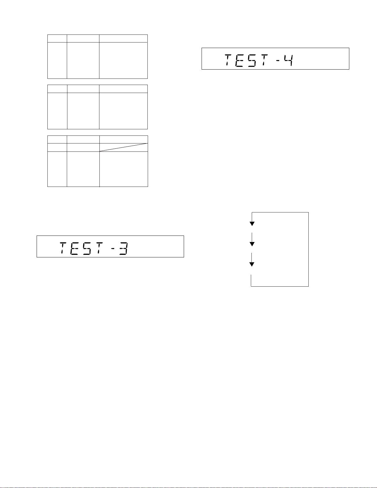
3.Preset frequencies for various destinations
(random preset memory)
CH
1 FM 87.5 MHz
2 FM108.0 MHz
3 FM FM 98.0 MHz
4 STEREO FM 90.0 MHz
5 FM106.0 MHz
6 AM 530 kHz
7 AM1720 kHz
8 AM AM 990 kHz
9 AM 600 kHz
10 AM1400 kHz
CH
16-35
36 FM106.0 MHz
37 FM 90.0 MHz
38 FM FM 98.0 MHz
39 MONO FM108.0 MHz
40 FM 87.5 MHz
• The slant line sections of the table store no memory.
4. Electronic volume Test Mode (TEST 3)
When this test mode is obtained, the following display lights
for one second.
BAND
BAND
BAND
FM
AMCH
FM
CD-E500
CD-E55/E44
5. Timer test Mode (TEST 4)
When this test mode is obtained, the following display lights
for one second.
Set the current time and timer time according to the following
procedure to reproduce the timer.
1.Set the current time to 1:00, the timer to ON time 1:05, the
function to CD, and volume to STEP 12, respectively. One
minute is counted as one second, and the timer is reproduced.
The fade-in (when playback is started) is executed at a rate
of one step for 1 sec. After completion of fade-in, the fadeout is executed at a rate of one step for 1 sec (WAIT 1 sec
inserted).
After completion of fade-out, the power is turned off (after
WAIT 1 sec), and the mode is shifted to the standby.
The display during operation is the same as that of ordinary
timer operation.
6. FL Test Mode (TEST 5)
When the FL test mode is obtained, all the FL segments are
lighted. Then pressing the "PLAY" button switches display
as below.
Lighting of all segments
In this mode, volume is Volume -14 dB (STEP23), FLAT
AND X-BASS ON, and start-up function to CD, respectively.
The button operations in the test mode are the same as
those of ordinary operation except volume UP/DOWN.
(1) The display is the same as that of ordinary operation
except test mode setting.
(2) Unlike the ordinary state, the volume is controlled with
the volume UP/DOWN button in accordance with the
following three steps.
Volume-
> Volume-0 (STEP 30)
(3) X-BASS is switched when button is pressed..
∞ (STEP 0) <-> Volume-14 dB (STEP 23) <-
Lighting of odd segments
Lighting of even segments
– 13 –
CD-E500
CD-E55/E44
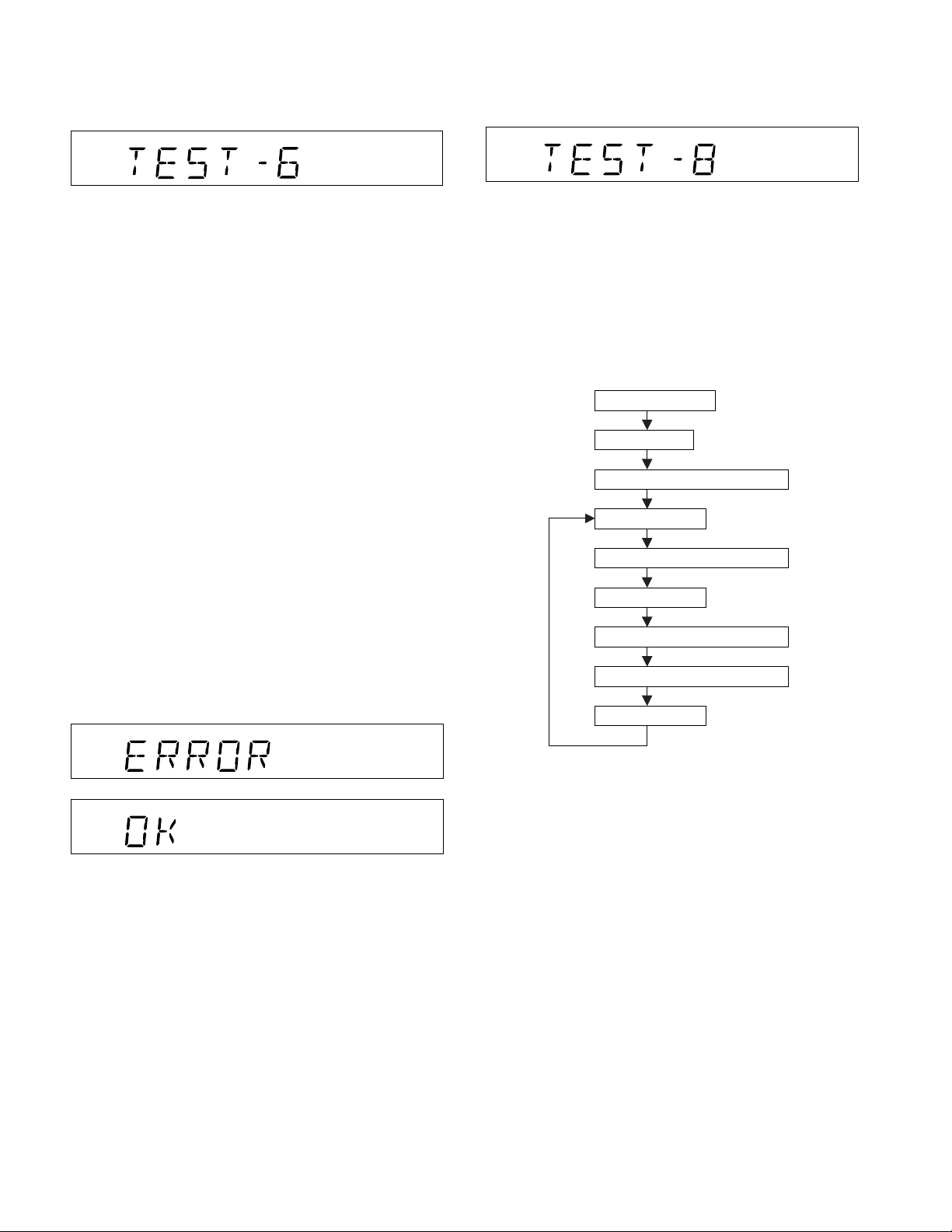
7. Button input diagnosis Test Mode (TEST 6)
When the test mode is obtained, the following is displayed.
(STAND-BY AND DEMO OFF STATUS)
8. CD MECHANISM Aging Test Mode (TEST 8)
OPEN/CLOSE & 3 DISC CHANGER aging test.
DISPLAY:
This test mode is intended to check whether all the main
unit buttons can be detected. Accordingly, in this test
mode, it is checked whether the "POWER ON/STAND BY"
button was pressed after all the buttons shown below were
pressed. If the result is OK, OK is displayed. If any one of
keys was not pressed, an error is displayed. In both cases
of OK termination or error termination, the mode is shifted
to the standby mode if the "POWER ON/STAND BY" button
is pressed subsequently.
All models using this type of microcomputer are not always
provided with the same buttons. Since the buttons used are
different depending on models, types of buttons to be used
are determined by whether SURROUND, and an electric lid
are available at the initial setting by MODEL port.
The order of buttons to be pressed is not determined.
Accordingly, it is checked whether all buttons have been
pressed.
1. PU-IN buttons: REW/PRESET DOWN + CD STOP
Since this model is provided with SURROUND (HAVE
OR NOT), and electric CD lid, the following 10 buttons
are detected as all buttons.
PLAY, X-BASS/DEMO, FUNCTION, VOLUME UP/
DOWN, MEMORY/SET, REW, FF, STOP, CD-OPEN/
CLOSE
The OK/NG display of test result is as follows.
FUNCTION:
Enter the TEST MODE 8, MCU control the 3 DISC
CHANGER OPEN/CLOSE. After open finished, tray rotate
1 circle (360 degree). Then close, After close finished, tray
rotate 1 circle (360 degree) again.
Request:
Every period include 4 operation. Below is TIMING:
Enter test mode
CHANGER
Find the disc 1 position
open
delay 3S after open finish
rotate 1 circle
close
delay 3S after close finish
rotate 1 circle
– 14 –
NOTES ON SCHEMATIC DIAGRAM
• Resistor:
To differentiate the units of resistors, such symbol as K and
M are used: the symbol K means 1000 ohm and the symbol
M means 1000 kohm and the resistor without any symbol is
ohm-type resistor. Besides, the one with “Fusible” is a fuse
type.
• Capacitor:
To indicate the unit of capacitor, a symbol P is used: this
symbol P means pico-farad and the unit of the capacitor
without such a symbol is microfarad. As to electrolytic
capacitor, the expression “capacitance/withstand voltage”
is used.
(CH), (TH), (RH), (UJ): Temperature compensation
(ML): Mylar type
(P.P.): Polypropylene type
• Schematic diagram and Wiring Side of P.W.Board for this
model are subject to change for improvement without prior
notice.
CD-E500
CD-E55/E44
• The indicated voltage in each section is the one measured
by Digital Multimeter between such a section and the chassis with no signal given.
1. In the tuner section,
indicates AM
indicates FM stereo
2. In the main section, a tape is being played back.
3. In the deck section, a tape is being played back.
4. In the power section, a tape is being played back.
5. In the CD section, the CD is stopped.
• Parts marked with “ 1 ” ( ) are important for
maintaining the safety of the set. Be sure to replace these
parts with specified ones for maintaining the safety and
performance of the set.
REF. NO
SW1 PICKUP IN ON—OFF
SW401 DISC UP/DOWN ON—OFF
SW402 OPEN/CLOSE ON—OFF
SW403 DISC NO. ON—OFF
SW404 DISC 1 ON—OFF
SW701 X-BASS/DEMO ON—OFF
SW702 POWER ON/STAND-BY ON—OFF
SW703 OPEN/CLOSE ON—OFF
SW704 DISK SKIP ON—OFF
SW705 VIDEO/AUX ON—OFF
SW706 TAPE ON—OFF
SW707 PRESET DOWN ON—OFF
SW708 PLAY/REPEAT ON—OFF
SW709 PRESET UP ON—OFF
SW710 STOP ON—OFF
DESCRIPTION
POSITION
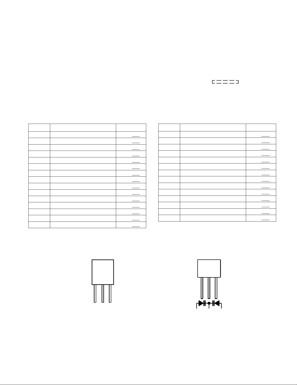
TYPES OF TRANSISTOR AND LED
REF. NO DESCRIPTION POSITION
SW711 MEMORY/SET ON—OFF
SW712 TUNING/TIME DOWN ON—OFF
SW713 TUNING/TIME UP ON—OFF
SW714 TIMER/SLEEP ON—OFF
SW715 CLOCK ON—OFF
SW719 EQUALIZER ON—OFF
SW720 VOLUME UP ON—OFF
SW721 VOLUME DOWN ON—OFF
SW722 TUNER(BAND) ON—OFF
SW723 CD ON—OFF
SW724 REC/PAUSE ON—OFF
SW801 TAPE2 INITIALIZE ON—OFF
SW802 TAPE1 INITIALIZE ON—OFF
SW803 TAPE2 REC ON—OFF
FRONT
VIEW
E C B
(S) (G) (D)
(1) (2) (3)
HSB562 C
HSC1609 GR
KRA102 M
KRA107 M
KRC102 M
KRC104 M
KRC107 M
KSA1015 GR
KSA1271 Y
KSC1815 GR
KSC3203 Y
SSC1674 C
2SC2001 K
123
KDV147B
SVC348S
– 15 –
CD-E500
V
V
–
+
+
+
+
+
O
2
CD-E55/E44
AM LOOP
ANTENNA
FROM
CD SECTION
CNS205
RECORD/
PLAYBACK HEAD
TAPE 2
ERASE
HEAD
TAPE 2
SW801
INITIALIZE
SW803
REC
SOL801
SOLENOID
PHOTE INTERRUPTER
FM
ANTENNA
3
2
1
CNP301
TAPE 1
PLAYBACK
HEAD
L-CH
R-CH
P.B.
L-CH
R-CH
CNP205
1
2
3
REC
SWITCHING
B.P.F
BF301
AM TRACKING
T302
L
R
Q801
Q803
+B2
Q821
Q822
Q823
BIAS CONT
SWITCHING
SWITCHING
TA7358AP
1
FM FRONT END
2
3
FM RF
L302
SWITCHING
Q807,Q808
Q813,Q814
Q802
Q810
Q811
Q820
6
IC301
4
5
T306
SWITCHING
SWITCHING
COVERAGE
L REC
R REC
FM IF FM IF
7
FM
T304
8
OSC
CF303
9
FM MPX./AM IF
L303
OSC BUFF
Q302
AM BAND
FM
SWITCHING
L(T1)
1
R(T1)
24
2
L(T2)
R(T2)
23
L NF
3
R NF
22
6
REC
9
16
REF
14
15
1211
M801
TAPE
MOTOR
Q306
IC303
LA1832S
FM IF DET./
FM MUTE
LEVEL
VR351
FM OSC
VT
20
FM
Q360
13
P.B
21
L
4
R
5
20
L REC
7
R
18
L NF
8
R NF
17
ALC
10
19
M
CF302
CF352
T351
AM IF
4
IF OUT
GND
VCC
76
SD
STEREO
CE
3
985
FM/AM
OUT
18
DI
4
21
AM IF
10
AM IN
11
1516
MO/ST
FM/AM
10
98
AM OSC
OUT
2324
X352
4.5 MHz
1
OSC
1
2
AM MIX
IC303
LA1832S
21
AM RF IN
AM OSC IN
FM IN
22
IC302
LC72131
PLL(TUNER)
7
+B2
PB
IC801
AN7345K
PLAYBACK AND RECORD
/PLAYBACK AMP.
Q812
Q819
+B2
TAPE MPTOR
DRIVER
Q815 Q818
Q804 Q817
SOLENOID
DRIVER
CF351
FM
VCO
DET
MPXIN
16
DO
CL
5
6
MUTE
T2_RUN_PLUS
T1_RUN_PLUS
DZH05C2+
X351
456 kHz
13
17
MO/ST
L
R
FM/AM
12
Q351
SWITCHING
17
TAPE_SW
T2_SOL
T1_SOL
CH_SW
T_MOTOR
REC/PLAY
REC
14
15
BIAS
CNP803
1
2
3
4
5
6
7
8
9
10
DISPLAY
+B2
CNP202
CE
SD
FM ST
TUNER
CNS803
FROM
DISPLAY SECTION
CL
AUX
TAPE
CD
FR
CNS
34567
DO
DI
L
R
L
R
L
R
L
R
TAPE 1
SW802
INITIALIZE
SOL802
SOLENOID
PHOTE INTERRUPTER
Q809
U_CON5V
Q806
+B3
+B2
Q805 Q816
SOLENOID
DRIVER
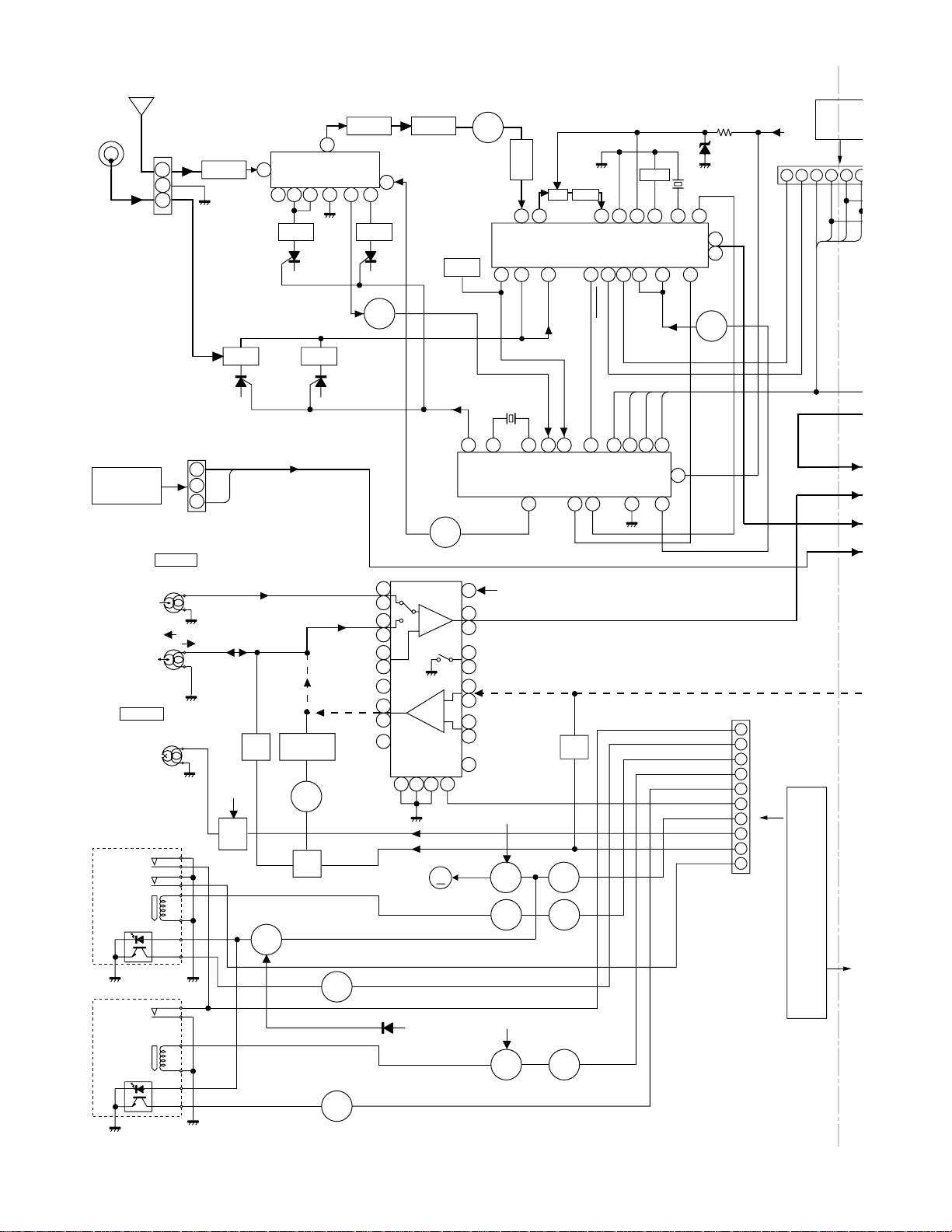
Figure 16 BLOCK DIAGRAM (1/4)
– 16 –
CNS901
DG
CD-E500
FROM
CD-E55/E44
FROM
DISPLAY SECTION
CNS202
02
DI
CL
CE
DO
9
L
AUX
R
16
10
L
TAPE
R
15
L
11
TUNER
R
14
L
12
CD
R
13
FROM
CD SECTION
CNS204
12345
DI
CL
DO
D_GND
SO601
VIDEO/AUX IN
IC601
LC75341M
AUDIO PROCESSOR
8
7
17
18
3
CNP204
+7V
M_GND
+B5
DI
CE
CL
23
+B2
654321
D_GND
1
2
24
21
4
+B4
SYSTEM
MUTE
Q101
Q102
IC101
STK40207
L
POWER AMP.
R
L
15
R
1
+VCC
PRE
+VCC
8
–VCC
9
PRE
12
–VCC
4
6
7
10
11
R-OUT
L-OUT
Q105
Q106
Q203
Q103
Q104
Q108
Q109
RLY101
+B2
CD_+B
MUTE
SIGAL_LVL
SP_RLY
SP_DETECT
FAN_START
FAN_PRT
Q107
Q208
CNP102
FAN MOTOR
DRIVER
Q201,202
Q204,205
+B3
1
2
3
4
5
6
7
M
SO101
SPEAKER
TERMINAL
HEADPHONES
FROM
CNS102
DISPLAY SECTION
M101
FAN
MOTOR
JK101
CD+B
+B4
+B5
A_12V
+B2
CNP901
1
VF1
DISPLAY SECTION
CNS901
VF2
–B2
+B3
DGND
+B3
2
3
4
5
CD_7V
+5.6 V
+5.6 V
–30 V
Q207
VOLTAGE
REGULATOR
VF2
VF1
Q206
IC203
KIA7808API
VOLTAGE
REGULATOR
IC202
KIA7812API
VOLTAGE
REGULATOR
IC201
KIA7805API
VOLTAGE
REGULATOR
+B1
–B1
D905~D908
D901~D904
F902
5A/125V
Q901
VOLTAGE
REGULATOR
F901
5A/125V
F903
1.6A/125V
+B2
T901
POWER TRANSFORMER
AC POWER
SUPPLY CORD
AC 120 V,60 Hz
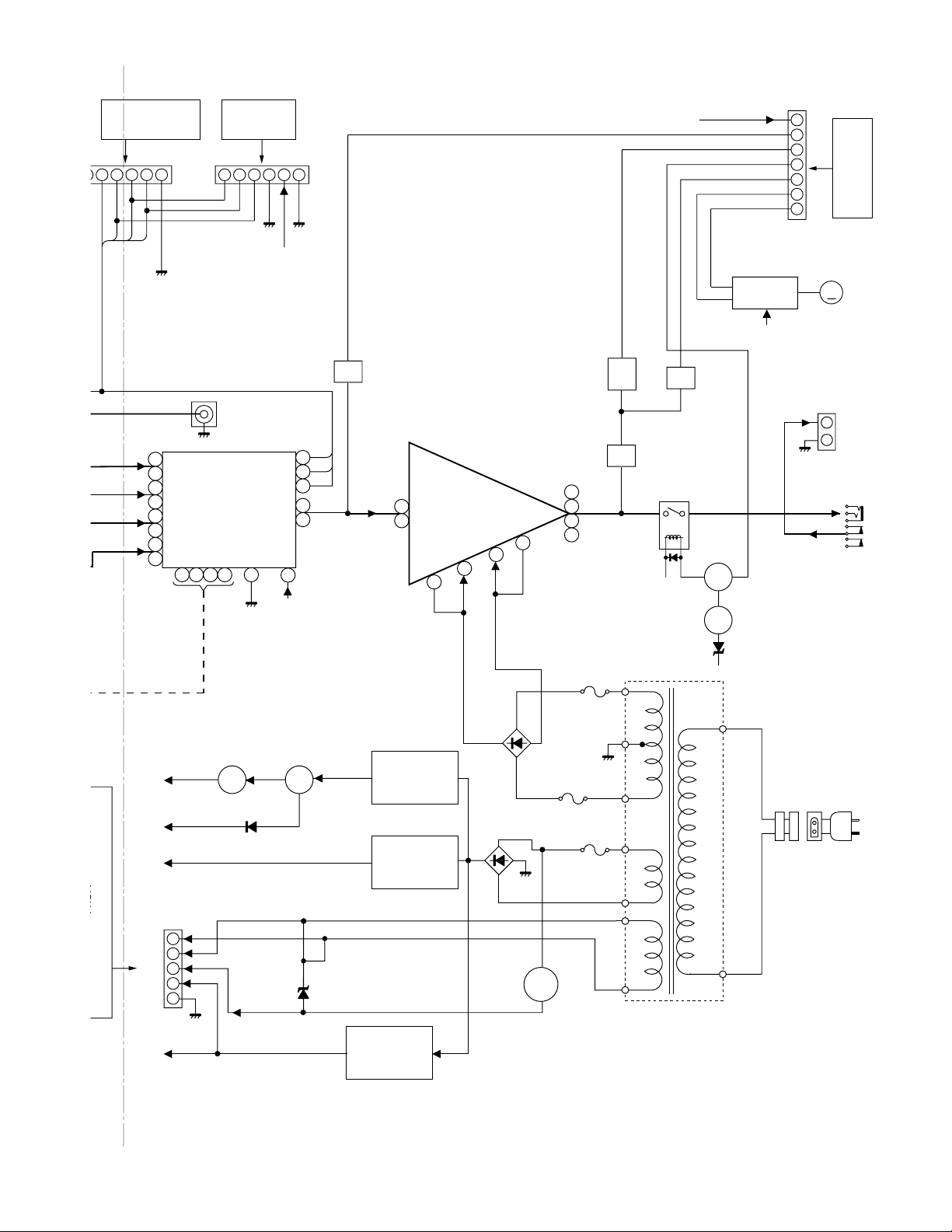
Figure 17 BLOCK DIAGRAM (2/4)
– 17 –
CD-E500
CD-E55/E44
TO MAIN SECTION
+3.3V
CNS205
CONSTANT
VOLTAGE
Q411
AGND
R-CH
32
XL401
16.9344 MHz
CLDIDO
+7V (+B5)
DGND
L-CH
1
MGND
5
64
312
CONSTANT
VOLTAGE
CNS204
Q412
45 68
75
69
57
56
55
51
50
44
43
40
37
28
19
48
49
42
LCHO
RCHO
SERVO/SIGNAL CONTROL
6
XOUT
XIN
VDD
XVDD
RFVDD
ADAVDD
5
38
77
47
18
+3.3V
VDD5
IC401
LC78646E
VVDD
VREF
11
41
LVDD
64 6566
46
DO
RVDD
TIN1 E
FIN2 B
FIN1 A
987
CE
ROTATE
DISC 1_SW
DRF
VWRQ
11 810 9 6745231
CNP405
616263
67
DI
10
CL
TIN2 F
79
DRF
LDS
80
Q409
RES
LDD
VWRQ
CONT4
CONT5
SLDO
SPDO
FDO
TDO
LASER
DRIVER
CE
25
26
23
22
21
20
+3.3V
+7V
+7V
CLOSE_SW
CD RES
Q401,402
Q403,404
Q405,406
Q407,408
MUTE
2
4
12
FOCUS/TRACKING/
19
27
1
VCC
VCC
30
VREF
29
25 2120 141526
UP_SW
DOWN_SW
OPEN_SW
DISC NO._SW
IC402
LA6548D
SPIN/SLED
DRIVER
REG_IN
REG_OUT
+3.3V
+
M
–
–
M
+
M401
UP/DOWN LOADING
MOTOR
6
51110
SW401
DISC
UP/DOWN
SW402
OPEN/CLOSE
SW403
DISC NO.
SW404
DISC 1
M402
ROTATE
MOTOR
24
~~
22
9
7
+5V
VCC
E
C
A
B
C
VC
F
LD
MD
+
M
–
–
M
+
SW1
PICKUP IN
FOCUS COIL
TRACKING COIL
CD PICKUP UNIT
NM802
SPINDLE
MOTOR
NM801
SLED
MOTOR
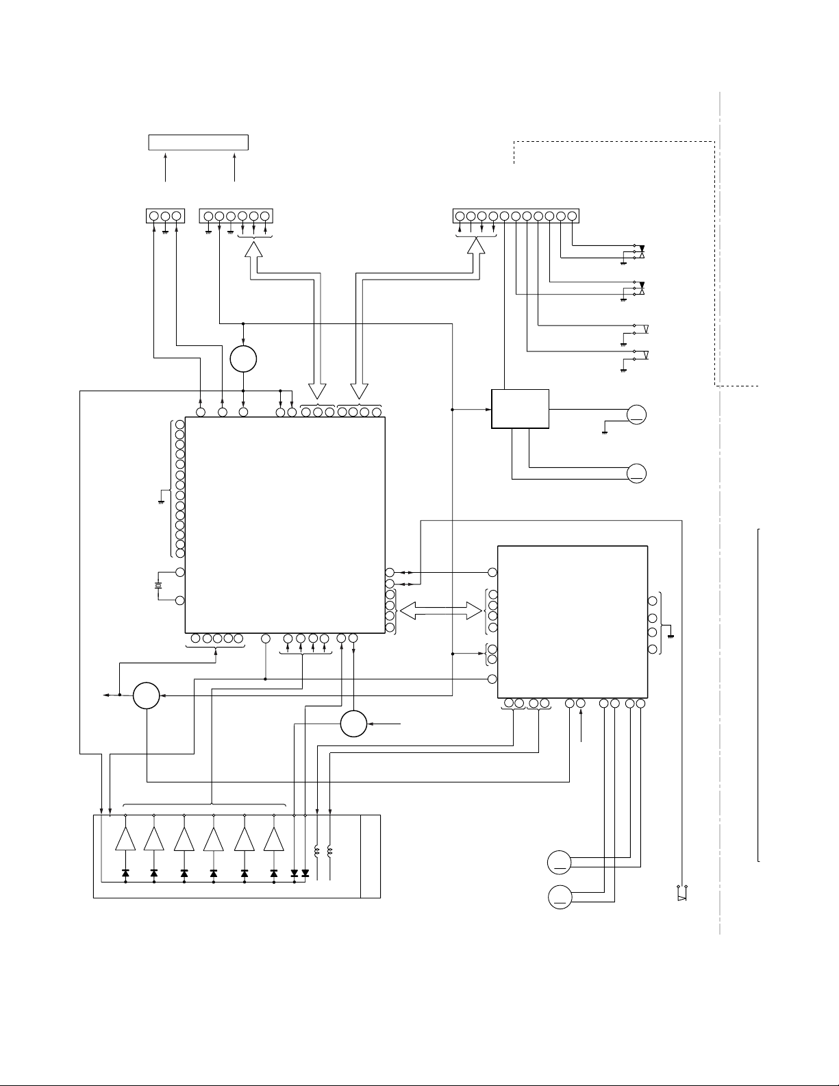
Figure 18 BLOCK DIAGRAM (3/4)
– 18 –
 Loading...