


27F630
27F631
SERVICE MANUAL
S13W527F630//
COLOR TELEVISION
Chassis No. GB-3U
27F630
MODELS 27F631
In the interests of user-safety (Required by safety regulations in some countries ) the set should be restored to its original condition and only parts identical to those specified should be used.
CONTENTS |
|
|
Page |
È ELECTRICAL SPECIFICATIONS ......................................................................................................... |
1 |
ÈIMPORTANT SERVICE SAFETY PRECAUTION ................................................................................. |
2 |
ÈLOCATION OF USER'S CONTROL ..................................................................................................... |
4 |
È INSTALLATION AND SERVICE INSTRUCTIONS ................................................................................ |
5 |
È SERVICE ADJUSTMENT ..................................................................................................................... |
9 |
È CHASSIS LAYOUT ............................................................................................................................. |
12 |
È BLOCK DIAGRAM .............................................................................................................................. |
13 |
È DESCRIPTION OF SCHEMATIC DIAGRAMS & WAVEFORMS ........................................................ |
14 |
È SCHEMATIC DIAGRAMS ................................................................................................................... |
15 |
È PRINTED WIRING BOARD ASSEMBLIES ........................................................................................ |
23 |
È REPLACEMENT PARTS LIST ............................................................................................................ |
27 |
È PACKING OF THE SET ...................................................................................................................... |
35 |
ELECTRICAL SPECIFICATIONS |
|
POWER INPUT ..................................................... |
|
120V AC, 60 Hz |
POWER RATING .................................................................. |
|
135W |
PICTURE SIZE ....................................... |
|
2,193.5 cm2 (339sq inch) |
CONVERGENCE ............................................................. |
|
Magnetic |
SWEEP DEFLECTION .................................................... |
|
Magnetic |
FOCUS ............................................... |
|
Hi-Bi-Potential Electrostatic |
INTERMEDIATE FREQUENCIES |
|
|
Picture IF Carrier Frequency ..................................... |
45.75 MHz |
|
Sound IF Carrier Frequency |
...................................... |
41.25 MHz |
Color Sub-Carrier Frequency .................................... |
42.17 MHz |
|
|
|
(Nominal) |
AUDIO POWER |
|
|
OUTPUT RATING .............. |
5.0W + 5.0W (at 10% distortion and |
|
|
|
Dual CH Operate) |
SPEAKER |
|
SIZE ........................................................ |
12 x 6 cm oval (2 pcs.) |
VOICE COIL IMPEDANCE ............................... |
8 ohm at 400 Hz |
ANTENNA INPUT IMPEDANCE |
|
VHF/UHF ..................................................... |
75 ohm Unbalanced |
TUNING RANGES |
|
VHF-Channels ............................................................... |
2 thru 13 |
UHF-Channels ............................................................ |
14 thru 69 |
CATV Channels ........................................................... |
1 thru 125 |
|
(EIA, Channel Plan U.S.A.) |
Specifications are subject to change without prior notice.
SHARP CORPORATION |
This document has been published to be used for after |
sales service only. |
|
|
The contents are subject to change without notice. |

27F630
27F631
IMPORTANT SERVICE SAFETY PRECAUTION
èService work should be performed only by qualified service technicians who are thoroughly familiar with all safety checks and the servicing guidelines which follow:
WARNING
1.For continued safety, no modification of any circuit should be attempted.
2.Disconnect AC power before servicing.
3.Semiconductor heat sinks are potential shock hazards when the chassis is operating.
4.The chassis in this receiver has two ground systems which are separated by insulating material. The nonisolated (hot) ground system is for the B+ voltage regulator circuit. The isolated ground system is for the low B+ DC voltages and the secondary circuit of the high voltage transformer.
To prevent electrical shock use an isolation transformer between the line cord and power receptacle, when servicing this chassis.
CAUTION: FOR CONTINUED
PROTECTION AGAINST A
RISK OF FIRE, REPLACE
4A 125V ONLY WITH SAME TYPE 4A-
125V FUSE.
SERVICING OF HIGH VOLTAGE SYSTEM AND PICTURE TUBE
When servicing the high voltage system, remove the static charge by connecting a 10k ohm resistor in series with an insulated wire (such as a test probe) between the picture tube ground and the anode lead. (AC line cord should be disconnected from AC outlet.)
1.Picture tube in this receiver employs integral implosion protection.
2.Replace with tube of the same type number for continued safety.
3.Do not lift picture tube by the neck.
4.Handle the picture tube only when wearing shatterproof goggles and after discharging the high voltage anode completely.
X-RADIATION AND HIGH VOLTAGE LIMITS
1.Be sure all service personnel are aware of the procedures and instructions covering X-radiation. The only potential source of X-ray in current solid state TV receivers is the picture tube. However, the picture tube does not emit measurable X-Ray radiation, if the high voltage is as specified in the "High Voltage Check" instructions.
It is only when high voltage is excessive that X- radiation is capable of penetrating the shell of the picture tube including the lead in the glass material. The important precaution is to keep the high voltage below the maximum level specified.
2.It is essential that servicemen have available at all times an accurate high voltage meter.
The calibration of this meter should be checked periodically.
3.High voltage should always be kept at the rated value −no higher. Operation at higher voltages may cause a failure of the picture tube or high voltage circuitry and;also, under certain conditions, may produce radiation in exceeding of desirable levels.
4.When the high voltage regulator is operating properly there is no possibility of an X-radiation problem. Every time a color chassis is serviced, the brightness should be tested while monitoring the high voltage with a meter to be certain that the high voltage does not exceed the specified value and that it is regulating correctly.
5.Do not use a picture tube other than that specified or make unrecommended circuit modifications to the high voltage circuitry.
6.When trouble shooting and taking test measurements on a receiver with excessive high voltage, avoid being unnecessarily close to the receiver.
Do not operate the receiver longer than is necessary to locate the cause of excessive voltage.
2
27F630
27F631
IMPORTANT SERVICE SAFETY PRECAUTION
(Continued)
BEFORE RETURNING THE RECEIVER
(Fire & Shock Hazard)
Before returning the receiver to the user, perform the following safety checks.
1.Inspect all lead dress to make certain that leads are not pinched or that hardware is not lodged between the chassis and other metal parts in the receiver.
2.Inspect all protective devices such as non-metallic control knobs, insulating materials, cabinet backs, adjustment and compartment covers or shields, isolation resistor-capacity networks, mechanical insulators, etc.
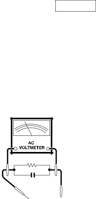
3.To be sure that no shock hazard exists, check for leakage current in the following manner.
•Plug the AC cord directly into a 120 volt AC outlet, (Do not use an isolation transformer for this test).
•Using two clip leads, connect a 1.5k ohm, 10 watt resistor paralleled by a 0.15 F capacitor in series with all exposed metal cabinet parts and a known earth ground, such as electrical conduit or electrical ground connected to earth ground.
•Use an AC voltmeter having with 5000 ohm per volt, or higher, sensitivity to measure the AC voltage drop across the resistor.
•Connect the resistor connection to all exposed metal parts having a return to the chassis (antenna, metal cabinet, screw heads, knobs and control shafts, escutcheon, etc.) and measure the AC voltage drop across the resistor.
AII checks must be repeated with the AC line cord plug connection reversed. (If necessary, a nonpolarized adapter plug must be used only for the purpose of completing these check.)
Any current measured must not exceed 0.5 milliamp. Any measurements not within the limits outlined above indicate of a potential shock hazard and corrective action must be taken before returning the instrument to the customer.
1.5k ohm |
10W |
0.15 F
TEST PROBE
TO EXPOSED
METAL PARTS CONNECT TO
KNOWN EARTH
GROUND
1234567890123456789012345678901212345678901234567890123456789012123456789012345678901234567890121 2
1234567890123456789012345678901212345678901234567890123456789012123456789012345678901234567890121 2
SAFETY NOTICE
Many electrical and mechanical parts in television receivers have special safety-related characteristics. These characteristics are often not evident from visual inspection, nor can protection afforded by them be necessarily increased by using replacement components rated for higher voltage, wattage, etc.
Replacement parts which have these special safety characteristics are identified in this manual; electrical components having such features are identified by "Œ" and shaded areas in the Replacement Parts Lists and Schematic Diagrams.
For continued protection, replacement parts must be identical to those used in the original circuit. The use of substitute replacement parts which do not have the same safety characteristics as the factory recommended replacement parts shown in this service manual, may create shock, fire, X-radiation or other hazards.
1234567890123456789012345678901212345678901234567890123456789012123456789012345678901234567890121 2
12345678901234567890123456789012123456789012345678901234567890121234567890123456789012345678901212
3

27F630
27F631
LOCATION OF USER'S CONTROL
Front Panel |
|
POWER |
|
Press → On. |
|
Press again → Off. |
|
REMOTE CONTROL |
|
SENSOR |
|
MENU |
|
Press → Accesses MAIN MENU. |
VOLUME UP/DOWN |
Press again → Exits MAIN MENU. |
|
|
( +) Increases sound. |
|
( —) Decreases sound. |
INSIDE DOOR
VIDEO/AUDIO IN 2
TERMINALS
CHANNEL UP/DOWN
(') Selects next higher channel. (") Selects next lower channel.
Basic Remote Control Functions
POWER
Press → On.
Press again → Off.
REMOTE KEYPAD
Accesses any channel from keypad.
FLASHBACK
Returns to previous channel.
PERSONAL PREFERENCE
With the Personal Preference buttons, you can program your favorite programs by using the 4 categories A, B, C and D. The channels can be accessed quickly by using these buttons.
VOLUME UP/DOWN
( + ) Increases sound.
(—) Decreases sound.
•Changes or selects the TV adjustments on On-Screen Display.
MENU
Press → Accesses MAIN MENU. Press again → Exits MAIN MENU.
MUTE
Press → Mutes sound.
Press again → Restores sound.
•When sound is muted, CLOSED CAPTION appears if available.
POWER (DVD/VCR)
Press → On.
Press again → Off.
DVD/VCR CONTROL
Note:
Infrared Transmitter Window
CATV/DVD-TV/VCR MODE buttons
Press TV/VCR→ Signals sent will be for TV and VCR control.
Press CATV/DVD → Signals sent will be for cable TV converter and DVD control.
DISPLAY
Press → Displays receiving channel for 4 seconds.
Press again → Removes display.
•Temporarily displays receiving channel when in Closed Caption mode.
INPUT
Press → Switches to external video INPUT 1 mode.
Press twice → Switches to external video INPUT 2 mode.
Press 3 times → Switches to external video INPUT 3 mode or COMPONENT mode.
Press 4 times → Switches back to the original TV mode.
ENTER
Used in some instances where a Cable Converter Box requires an “enter” command after selecting channels, when using the REMOTE KEYPAD button.
CHANNEL UP/DOWN
(') Selects next higher channel. (") Selects next lower channel.
•Moves the “ ” mark on the MENU screens.
SKIP/VCR-CH
REC
•The above shaded buttons on the Remote Control glow in the dark. To use the glow-in-the-dark display on the remote control, place it under a fluorescent light or other lighting.
•The phosphorescent material contains no radioactive or toxic material, so it is safe to use.
•The degree of illumination will vary depending on the strength of lighting used.
•The degree of illumination will decrease with time and depending on the temperature.
•The time needed to charge the phosphorescent display will vary depending on the surrounding lighting.
•Sunlight and fluorescent lighting are the most effective when charging the display.
4

27F630
27F631
INSTALLATION AND SERVICE INSTRUCTIONS
Note: (1) When performing any adjustments to resistor controls and transformers use non-metallic screwdrivers or TV alignment tools.
(2) Before performing adjustments, the TV set must be on at least 15 minutes.
CIRCUIT PROTECTION
The receiver is protected by a 4.0A fuse (F701), mounted on PWB-A, wired into one side of the AC line input.
X-RADIATION PROTECTOR CIRCUIT TEST
After service has been performed on the horizontal deflection system, high voltage system, B+ system, test the X-Radiation protection circuit to ascertain proper operation as follows:
1.Apply 120V AC using a variac transformer for accurate input voltage.
2.Allow for warm up and adjust all customer controls for normal picture and sound.
3.Receive a good local channel.
4.Connect a digital voltmeter to TP651 (Pin 3) and make sure that the voltmeter reads 13.85 ±0.6V DC.
5.Apply external 17.3V DC at TP651 by using an external DC supply, TV must be shut off.
6.To reset the protector, unplug the AC cord and plug the AC cord power on. Now make sure that normal picture appears on the screen.
7.If the operation of the horizontal oscillator does not stop in step 5, the circuit must be repaired before the set is returned to the customer.
HIGH VOLTAGE CHECK
High voltage is not adjustable but must be checked to verify that the receiver is operating within safe and efficient design limitations as specified checks should be as follows:
1.Connect an accurate high voltage meter between ground and anode of picture tube.
2.Operate receiver for at least 15 minutes at 120V AC line voltage, with a strong air signal or a properly tuned in test signal.
3.Enter the service mode and select the service adjustment "V11" and Bus data "01" (Y-mute on, CRT Cut Off).
4.The voltage should be below 31.5kV (at zero beam). If a correct reading cannot be obtained, check circuitry for malfunctioning components. After the voltage test, make Y-mute off to the normal mode.
5

27F630
27F631
For adjustments of this model, the bus data is converted to various analog signals by the D/A converter circuit.
Note: There are still a few analog adjustments in this series such as focus and master screen voltage. Follow the steps below whenever the service adjustment is required. See "Table-B" to determine, if service adjustments are required.
1. Service mode
Before putting unit into the service mode, check that customer adjustments are in the normal mode. Use the reset function in the video adjustment menu to ensure customer controls are in their proper (reset) position.
2. Service number selection
Once in the service mode, press the Ch-up or Chdown button on the remote controller or at the set. The service adjustment number will vary in increments of one, from "V01" to "P08". Select the item you wish to adjust.
To enter the service mode and exit service mode.
To enter the service mode manually just press and hold the Vol-down and Ch-up buttons at the same time, plug the AC cord into a wall socket.
Now the TV set is switched on and enters the service mode.
To exit the service mode, turn the television off by pressing the power button.
3. Data number selection
Press the Vol-up or Vol-down button to adjust the data number.
DATA NUMBER |
|
CHANNEL |
||
|
||||
SERVICE ADJUSTMENT NUMBER |
|
|
|
|
|
|
|
|
|
|
|
|
|
|
|
|
|
|
|
V01 55(085) 2
Figure A.
6
|
|
|
|
|
|
|
27F630 |
|
|
|
|
|
|
|
|
27F631 |
|
A. VCJ IC ADJUSTMENT |
|
|
|
|
|
|
|
|
|
|
|
|
|
|
|
|
|
SERVICE |
ADJUSTMENT ITEM |
DATA |
|
|
NOTES |
FIXED VALUE |
|
|
NUMBER |
|
|
|
|
(HEX) |
|
||
|
RANGE |
|
INITIAL VALUE |
|
|
|||
|
|
|
|
|
|
|||
|
|
|
|
|
|
|
|
|
V01 |
PICTURE |
0-15 (00h-0Fh) |
|
8 (08h) |
|
|
|
|
V02 |
TINT |
0-127 (00h-7Fh) |
|
66 |
(42h) |
|
|
|
V03 |
COLOR |
0-127 (00h-7Fh) |
|
56 |
(38h) |
|
|
|
V05 |
BRIGHT |
0-127 (00h-7Fh) |
|
64 |
(40h) |
|
|
|
V06 |
R CUT-OFF |
64-255 (40h-FFh) |
|
64 |
(40h) |
|
|
|
V07 |
G CUT-OFF |
64-255 (40h-FFh) |
|
64 |
(40h) |
|
|
|
V08 |
B CUT-OFF |
64-255 (40h-FFh) |
|
64 |
(40h) |
|
|
|
V09 |
G/R DRIVE |
0-127 (00h-7Fh) |
|
64 |
(40h) |
|
|
|
V10 |
B DRIVE |
0-127 (00h-7Fh) |
|
64 |
(40h) |
|
|
|
V11 |
Y-MUTE/V-STOP |
0-2 |
|
0 (00h) |
Y-Mute / Holizontal “—” |
|
|
|
V12 |
SHARP |
0-63 (00h-3Fh) |
|
50 |
(32h) |
|
32 |
|
V13 |
DC RESTORATION |
0-3 (00h-03h) |
|
2 (02h) |
|
02 |
|
|
V14 |
BLACK STRETCH |
0-3 (00h-03h) |
|
2 (02h) |
|
02 |
|
|
V15 |
ABL START POINT |
0-3 (00h-03h) |
|
3 (03h) |
|
03 |
|
|
V16 |
ABL GAIN |
0-3 (00h-03h) |
|
2 (02h) |
|
02 |
|
|
V17 |
γ POINT |
0-3 (00h-03h) |
|
0 (00h) |
|
00 |
|
|
V19 |
ENERGY SAVE |
0-63 (00h-3Fh) |
|
63 |
(3Fh) |
Offset |
3F |
|
V24 |
LOW-G |
0-255 (00h-FFh) |
|
12 |
(0Ch) |
Color Temp. |
F4 |
|
V25 |
LOW-B |
0-255 (00h-FFh) |
|
241 (F1h) |
Color Temp. |
E6 |
|
|
V26 |
ML-G |
0-255 (00h-FFh) |
|
0 (00h) |
Color Temp. |
FD |
|
|
V27 |
ML-B |
0-255 (00h-FFh) |
|
247 (F7h) |
Color Temp. |
F8 |
|
|
V28 |
HIGH-G |
0-255 (00h-FFh) |
|
2 (02h) |
Color Temp. |
01 |
|
|
V29 |
HIGH-B |
0-255 (00h-FFh) |
|
8 (08h) |
Color Temp. |
06 |
|
|
V30 |
WPL |
0-1 |
|
1 (01h) |
|
01 |
|
|
V31 |
RGB CONTRAST |
0-63 (00h-3Fh) |
|
59 |
(3Bh) |
|
3B |
|
V34 |
VSM GAIN |
0-3 (00h-03h) |
|
1 (01h) |
|
01 |
|
|
V36 |
BPF/TOF-INPUT |
0-1 |
|
0 (00h) |
External Input |
00 |
|
|
V37 |
CORING |
0-1 |
|
0 (00h) |
|
00 |
|
|
V38 |
VSM PHASE |
0-1 |
|
0 (00h) |
|
00 |
|
|
V39 |
COLOR γ |
0-1 |
|
0 (00h) |
|
00 |
|
|
V40 |
SHARP-INPUT |
0-63 (00h-3Fh) |
|
44 |
(2Ch) |
External Input |
2C |
|
V41 |
TINT-INPUT |
0-127 (00h-7Fh) |
|
62 |
(3Eh) |
External Input |
3E |
|
V42 |
PICTURE-COMPONENT |
0-15 (00h-0Fh) |
|
6 (06h) |
Component Input |
|
|
|
V43 |
TINT-COMPONENT |
0-127 (00h-7Fh) |
|
62 |
(3Eh) |
Component Input |
3E |
|
V44 |
COLOR-COMPONENT |
0-127 (00h-7Fh) |
|
72 |
(48h) |
Component Input |
48 |
|
V45 |
BRIGHT-COMPONENT |
0-127 (00h-7Fh) |
|
84 |
(54h) |
Component Input |
|
|
V46 |
R CUT OFF-COMPONENT |
64-255 (00h-FFh) |
|
64 |
(40h) |
Component Input |
|
|
V47 |
G CUT OFF-COMPONENT |
64-255 (00h-FFh) |
|
64 |
(40h) |
Component Input |
|
|
V48 |
B CUT OFF-COMPONENT |
64-255 (00h-FFh) |
|
64 |
(40h) |
Component Input |
|
|
V49 |
G/R DRIVE-COMPONENT |
0-127 (00h-7Fh) |
|
64 |
(40h) |
Component Input |
|
|
V50 |
B DRIVE-COMPONENT |
0-127 (00h-7Fh) |
|
64 |
(40h) |
Component Input |
|
|
V51 |
SHARP-COMPONENT |
0-63 (00h-3Fh) |
|
44 |
(2Ch) |
Component Input |
2C |
|
V52 |
TINT-S |
0-127 (00h-7Fh) |
|
62 |
(3Eh) |
Component Input |
3E |
|
V53 |
C-TRAP |
0-1 (00h-01h) |
|
0 (00h) |
|
00 |
|
|
V59 |
AUTO FRESH |
0-1 (00h-01h) |
|
0 (00h) |
|
00 |
|
|
V60 |
SHARP P F |
0-1 (00h-01h) |
|
1 (01h) |
|
01 |
|
|
V61 |
CD MATRIX |
0-3 (00h-03h) |
|
2 (02h) |
|
02 |
|
|
V62 |
B-Y ATT |
0-1 (00h-01h) |
|
0 (00h) |
|
00 |
|
|
V63 |
R-Y ATT |
0-1 (00h-01h) |
|
0 (00h) |
|
00 |
|
|
V64 |
CD MATRIX COMPONENT |
0-3 (00h-03h) |
|
0 (00h) |
Component Input |
00 |
|
|
V65 |
B-Y ATT-COMPONENT |
0-1 (00h-01h) |
|
0 (00h) |
Component Input |
00 |
|
|
V66 |
R-Y ATT-COMPONENT |
0-1 (00h-01h) |
|
0 (00h) |
Component Input |
00 |
|
|
V67 |
BUZZ |
0-1 (00h-01h) |
|
1 (01h) |
|
01 |
|
|
V68 |
RGB ABCL |
0-1 (00h-01h) |
|
1 (01h) |
|
01 |
|
|
V69 |
PICTURE-VCOMP |
0-100 (00h-64h) |
|
47 |
(2Fh) |
16:9 Format (Offset) |
2F |
|
V70 |
COLOR-VCOMP |
0-100 (00h-64h) |
|
50 |
(32h) |
16:9 Format (Offset) |
32 |
|
V71 |
BRIGHT-VCOMP |
0-100 (00h-64h) |
|
51 |
(33h) |
16:9 Format (Offset) |
33 |
|
R01 |
RF-AGC |
0-63 (00h-3Fh) |
|
36 |
(24h) |
|
|
|
R03 |
RF-AGC REF |
0-255 (00h-FFh) |
|
170 (AAh) |
Standard value for the self-adjustment |
AA |
|
|
D01 |
V POSITION |
0-7 (00h-07h) |
|
0 (00h) |
|
00 |
|
|
D02 |
H POSITION |
0-31 (00h-1Fh) |
|
15 |
(0Fh) |
|
|
|
D03 |
V SIZE |
0-127 (00h-7Fh) |
|
89 |
(59h) |
|
|
|
D04 |
H SIZE |
0-63 (00h-3Fh) |
|
36 |
(24h) |
|
|
|
D05 |
V-LINEARITY |
0-15 (00h-0Fh) |
|
8 (08h) |
|
|
|
|
D06 |
V-S CORRECTION |
0-15 (00h-0Fh) |
|
12 |
(0Ch) |
|
0C |
|
D07 |
EW PARABOLA |
0-63 (00h-3Fh) |
|
43 |
(2Bh) |
|
|
|
D08 |
EW TRAPEZIUM |
0-63 (00h-3Fh) |
|
36 |
(24h) |
|
|
|
D10 |
AFC GAIN |
0-3 (00h-03h) |
|
2 (02h) |
|
02 |
|
|
D11 |
V EHT |
0-7 (00h-07h) |
|
6 (06h) |
|
06 |
|
|
D12 |
H EHT |
0-7 (00h-07h) |
|
6 (06h) |
|
06 |
|
|
D13 |
EW CORNER |
0-31 (00h-1Fh) |
|
8(08h) |
|
08 |
|
|
7

27F630
27F631
SERVICE |
ADJUSTMENT ITEM |
DATA |
|
NOTES |
FIXED VALUE |
|
NUMBER |
|
|
|
|||
|
RANGE |
|
INITIAL VALUE |
|
(HEX) |
|
|
|
|
|
|||
|
|
|
|
|
|
|
D14 |
EW CORNER BOTTOM |
19-81 (13h-51h) |
|
50 (32h) |
Offset toward D13. |
32 |
D15 |
NOISE DET LEVEL |
0-3 (00h-03h) |
|
0 (00h) |
|
00 |
D18 |
V CENTERING |
0-63 (00-3Fh) |
|
36 (24h) |
|
|
D19 |
V-AGC |
0-1 (00h-01h) |
|
0 (00h) |
|
00 |
|
|
|
|
|
|
|
B. SPECIAL SETTING
SERVICE |
ADJUSTMENT ITEM |
DATA |
|
|
NOTES |
FIXED VALUE |
|
NUMBER |
|
|
|
|
|||
|
RANGE |
|
INITIAL VALUE |
|
(HEX) |
||
|
|
|
|
||||
|
|
|
|
|
|
|
|
EX1 |
FAO VOLUME |
0-50 (00h-32h) |
|
36 |
(24h) |
|
24 |
EX2 |
CC-POSITION |
0-127 (00h-7Fh) |
|
27 |
(1Bh) |
|
1C |
EX3 |
INT |
0-255 (00h-FFh) |
|
122 (7Ah) |
Interrupt period adjustment. |
7A |
|
EX4 |
A-ATT |
0-127 (00h-7Fh) |
|
90 |
(5Ah) |
|
5A |
EX5 |
TUNER data |
0-3 (00h-03h) |
|
0 (00h) |
|
00 |
|
EX6 |
Think chip-Slice LEVEL |
0-255 (00h-FFh) |
|
54 |
(36h) |
|
12 |
EX7 |
RLY DELAY TIME |
0-255 (00h-FFh) |
|
0 (00h) |
For the power control |
00 |
|
EX8 |
ADG ON TIME |
0-255 (00h-FFh) |
|
10 |
(0Ah) |
For the power control |
0A |
|
|
|
|
|
|
|
|
C. OPTION SETTING
SERVICE |
ADJUSTMENT ITEM |
DATA |
|
|
NOTES |
FIXED VALUE |
|
NUMBER |
|
|
|
|
|||
|
RANGE |
|
INITIAL VALUE |
|
(HEX) |
||
|
|
|
|
||||
|
|
|
|
|
|
|
|
OP1 |
OPTION1 |
0-255 (00h-FFh) |
|
245 |
(F5h) |
|
F5 |
OP2 |
OPTION2 |
0-255 (00h-FFh) |
|
188 |
(BCh) |
|
BC |
OP3 |
OPTION3 |
0-255 (00h-FFh) |
|
15 (0Fh) |
|
0F |
|
|
|
|
|
|
|
|
|
D. SOUND ADJUSTMENT
SERVICE |
ADJUSTMENT ITEM |
DATA |
|
|
NOTES |
FIXED VALUE |
|
NUMBER |
|
|
|
|
|||
|
RANGE |
|
INITIAL VALUE |
|
(HEX) |
||
|
|
|
|
||||
|
|
|
|
|
|
|
|
M01 |
INPUT LEVEL |
0-15 (00h-0Fh) |
|
7 (07h) |
|
|
|
M02 |
MTS VCO |
0-63 (00h-3Fh) |
|
38 |
(26h) |
|
|
M03 |
FILTER |
0-63 (00h-3Fh) |
|
36 |
(24h) |
|
|
M04 |
WIDEBAND |
0-63 (00h-3Fh) |
|
28 |
(1Ch) |
|
|
M05 |
SPECTRAL |
0-63 (00h-3Fh) |
|
23 |
(17h) |
|
|
M09 |
SRS LEVEL |
0-255 (00h-FFh) |
|
224 (E0h) |
|
E0 |
|
M10 |
BBE LEVEL |
0-255 (00h-FFh) |
|
217 (D9h) |
|
D9 |
|
M11 |
SRS&BBE LEVEL |
0-255 (00h-FFh) |
|
208 (D0h) |
|
D0 |
|
M12 |
SRS&BBE OFF LEVEL |
0-255 (00h-FFh) |
|
228 (E4h) |
|
E4 |
|
M13 |
SRS Effect |
2-3 (02h-03h) |
|
2 (02h) |
|
02 |
|
M14 |
BBE-L Effect |
0-15 (00h-0Fh) |
|
15 |
(0Fh) |
|
0F |
M15 |
BBE-H Effect |
0-15 (00h-0Fh) |
|
15 |
(0Fh) |
|
0F |
M16 |
AGC Level |
0-7 (00h-07h) |
|
1 (01h) |
|
01 |
|
M17 |
BASS Offset |
0-31 (00h-1Fh) |
|
15 |
(0Fh) |
|
0F |
M18 |
TREBLE Offset |
0-31 (00h-1Fh) |
|
15 |
(0Fh) |
|
0F |
M19 |
BASS Offset-BBE |
0-31 (00h-1Fh) |
|
17 |
(11h) |
|
11 |
M20 |
TREBLE Offset-BBE |
0-31 (00h-1Fh) |
|
16 |
(10h) |
|
10 |
8
27F630
27F631
Holding down both the VOL-up and CH-up buttons on the TV set at service mode for more than 2 seconds will automatically write the above initial values into IC2101.
PART REPLACED |
ADJUSTMENT |
NOTES |
||
NECESSARY |
UNNECESSARY |
|||
|
|
|||
IC2001 |
|
X |
Data is stored in IC2101. |
|
IC201 |
X |
|
The adjustment is needed to compensate for characteristics of parts |
|
|
including IC201 and MTS level (M01). |
|||
|
|
|
||
|
|
|
|
|
|
X |
|
Holding down both the VOL-up and CH-up buttons on the TV set in |
|
IC2101 |
|
the service mode for more than 2 seconds will automatically write the |
||
|
|
|
above initial values into IC2101 Then perform a complete adjustment. |
|
|
|
|
|
|
CRT |
X |
|
Adjust items related to picture tube only. |
|
|
|
|
|
|
IC3001 |
X |
|
Adjust items related to MTS only (M01~M20). |
|
|
|
|
|
|
IC1801 |
X |
|
Adjust items related to P-IN-P only (P01~P08). |
|
|
|
|
|
|
SERVICE ADJUSTMENT
RF AGC Adjustment
1.Receive a good local channel.
2.Enter the service mode and select the service adjustment "R01".
3.Set the data value to point where no noise or beat appears.
4.Select another channel to confirm that no noise or beat appears.
Note 1 : You will have to come out of the service mode to select another channel.
Note 2 : Setting the data to "00" will produce a black raster.
Screen Adjustment
1.Receive a good local channel.
2.Enter the service mode and select the service adjustment "V03" and set the data value to "00" to set the color level to minimum. (Record original data code under adjustment "V03" before changing) You may skip this step, if you selected a B/W picture or monoscope pattern.
3.Select the service adjustment "V11" and adjust the data value to "01", this turn off the luminance signal (Y-mute).
4.Adjust the master screen control until the raster darkens to the point where raster is barely seen.
5.Adjust the service adjustments "V06" red, "V07" green and "V08" blue to obtain a good grey scale with normal whites at low brightness level.
6.Select the service adjustment "V11" and reset data to "00". Select the service adjustment "V03" and reset data to obtain normal color level.
7.For component input, the data value of "V46" red, "V47" green and "V48" blue is adjusted to follow the data value of "V06", "V07" and "V08" respectively.
8.Reset the master screen control to obtain normal brightness range.
White Balance Adjustment
1.Receive a good local channel.
2.Enter the service mode and select the service adjustment "V03" and set to "00" (minimum color)(Record original data code under adjustment "V03" before changing). "V03" does not have to be adjusted, if you selected a B/W picture or monoscope pattern.
3.Alternately adjust the service adjustment data of "V09" and "V10" until a good grey scale with normal whites is obtained. (RF Input)
4.For component input, the data value of "V49" and "V50" is adjusted to follow the data value of "V09" and "V10" respectively.
5.Select the service adjustment "V03" and reset data to obtain normal color level.
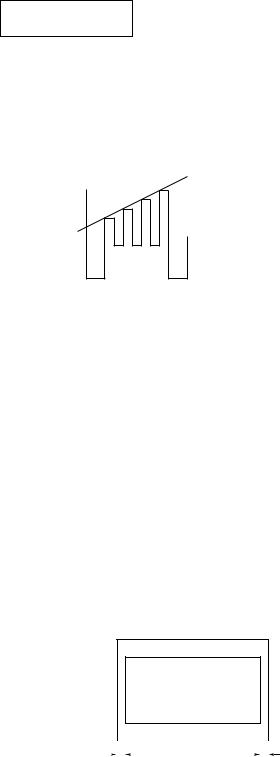
Sub-picture and Sub-Bright Adjustments
1.Receive the window pattern signal.
• RF INPUT (TU51)
2.Get into service adjustment data "V01" and "V05" and set the luminance as shown in figure "A" and "B" as
below respectively.
• COMPONENT INPUT
3.Get in service adjustment data "V42" and "V45" and set the luminance as shown in figure "A" and "B" as below respectively.
A B
LUMINESCENCE CONFIRMATION
A:120±10cd/m2
B:1.5±0.5cd/m2
9
27F630
27F631
Sub-Tint Adjustment
1.Receive the half color bar signal.
• RF INPUT (TU51)
2.Get into Y-Mute by R/C, or by setting the "V11" bus data to "01".
3.Vary the "V02" bus data until the waveform becomes as stated below.
LEVEL
B-AMP Base waveform in step (TP47B)
Sub-Color Adjustment
1.Receive a good local channel.
2.Make sure the customer color control is set to center
position .
• RF INPUT (TU51)
3.Enter the service mode and select service adjustment "V03".
4.Adjust "V03" data value to obtain a normal color level.
Focus Adjustment
1.Receive a good local channel.
2.Adjust the FOCUS VR of the flyback transformer to make the image as fine as possible.
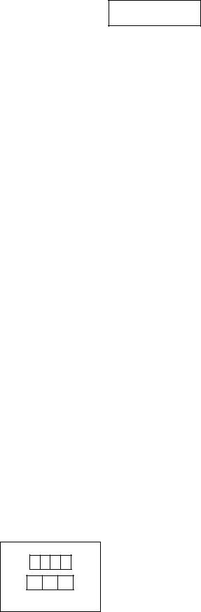
C. C Display Position Adjustment
1.Receive the lion head pattern signal.
2.Select "EX2" to display the text box.
3.Adjust the "EX2" bus data to let the text box displayed in the center.
DISPLAY OF TEXT BOX
TEXT BOX
| A-B | / 2
A |
|
|
|
|
|
B |
|
||
|
|
|
|
|
|
|
|
|
|
|
|
|
|
|
|
|
|
|
|
SPEC INSPECTION:| A-B | / 2 =< 5mm
Vertical-Size and Linearity Adjustments
1.Receive a good local channel. (SCREEN FORMAT 4:3)
2.Enter the service mode and select the service adjustment "D03" for V-size.
3.Adjust the "D03" bus data to get the proper V-size.
4.For V-linearity adjustment, select data bus "D05" and adjust to get the proper vertical linearity.
(SCREEN FORMAT 16:9)
5.Input data of "D22" to mines 38 step from "D03” data. (V-SIZE)
6.Input data of "D24" same as "D05" data. (V-LIN)
Note: Aging for 10 min before adjustment. After the adjustment of V-center and V-size, readjustment for this V-line.
Vertical Phase Adjustment
(SCREEN FORMAT 4:3)
1.Enter the service mode and input data of “00h” on "D01".
2.Adjust "D18" data value so that picture is centered. (SCREEN FORMAT 16:9)
3.Input data of "00h" on "D20".
4.Input data of "D34" same as "D18" data.
Horizontal Position Adjustment
1.Receive a good local channel. (SCREEN FORMAT 4:3)
2.Enter the service mode and select the service adjustment "D02".
3.Adjust "D02" data value so that picture is centered. (SCREEN FORMAT 16:9)
4.Input data of "D21" same as "D02" data.
Horizontal-Size Adjustment
1.Receive a good local channel. (SCREEN FORMAT 4:3)
2.Enter the service mode and select the service adjustment "D04" for H-size.
3.Adjust the "D04" bus data to get the proper H-size. (SCREEN FORMAT 16:9)
4.Input data of "D23" same as "D04" data.
EW-Parabola
1.Receive a good local channel. (SCREEN FORMAT 4:3)
2.Enter the service mode and select the service adjustment "D07" for EW parabola.
3.Adjust the "D07" bus data to get the proper vertical straight line for both left and right side.
(SCREEN FORMAT 16:9)
4. Input data of "D26" to mines 21 step from "D07" data.
EW-Trapezium
1.Receive a good local channel. (SCREEN FORMAT 4:3)
2.Enter the service mode and select the service adjustment "D08" for EW-Trapezium.
3.Adjust the "D08" bus data to get the best position display.
(SCREEN FORMAT 16:9)
4. Input data of "D27" same as "D08" data.
10
27F630
27F631
è MTS ADJUSTMENT
MTS Level Adjustment
1.Set the sound volume above 1.
Monoral signal: 400Hz, 100% modulation
2.Confirm "EX4" data is "5Ah".
3.Vary the "M01" bus data until the voltage to pin (39) of IC3001 to become the value as stated below.
SETTING VOLTAGE
ADJ spec : 490±10mVrms CHK spec: 490±20mVrms
MTS VCO Adjustment
1.Keep the unit in no-signal state.
2.Connect the frequency counter to pin (39) of IC3001.
3.Connect a capacitor (100 F, 50V) in between positive(+) side of C3005 and ground.
4.Enter the service mode and select the service adjustment "M02"
5.Adjust the data so that the frequency counter reads 62.94 ±0.75kHz.
Filter Adjustment
1.Feed the following stereo pilot signal to pin (14) of IC3001 at C3005 open.
Stereo pilot signal: 9.4kHz, 600mVrms.
2.Enter the service mode and select the service adjustment "M03".
3.Adjust the data until "OK" appears in position on the screen. Make sure the "OK" is displayed almost at the center of the data range.
Separation Adjustment
1.Input "SIGNAL 1" and vary the "M04" bus data to get the minimun AC voltage to pin (39) of IC3001.
2.Input "SIGNAL 2" and vary the "M05" bus data to get the minimun AC voltage to pin (39) of IC3001. SIGNAL 1: 300Hz, 30% modulation, Lch only, NR-ON SIGNAL 2: 3kHz, 30% modulation, Lch only, NR-ON
Note: SIGNAL 1 Adj. for widebando SIGNAL 2 Adj. for spectral
Check the output of the speaker at the maximum volume as stated below.
Confirmation spec:
ADJ spec: above 25 dB CHK spec: above 20 dB
11
 Loading...