


20U200
Sharp 20U200, 51U500, 51U550, 20U250, 51U200 Service Manual
...
20U200 51U200/500
20U200, 20U250
51U200, 51U250
51U500, 51U550
SERVICE MANUAL
S90i420U200//
COLOUR TELEVISION
Chassis No. UA-1
20U200, 20U250
20U250 51U250/550
MODELS
In the interests of user-safety (Required by safety regulations in some countries) the set should be restored to its original condition and only parts identical to those specified should be used.
51U200, 51U250
51U500, 51U550
FEATURE
Ë
Ë
Favorite Channel
Ë
Full Auto Search System
Ë
100 CH Program Memory
Ë
CATV (Hyper Band) Ready
Ë
AVL (Sound Keeper) Function
Ë
High Contrast Picture (Black Stretch Circuit)
Ë
ON Timer/Sleep T imer/Reminder Timer
Ë
Blue Back Noise Mute
Ë
Front AV In and Rear AV In/Out Terminals
Rear Sub-Woofer Terminal
Ë
Front Headphone Jack
Ë
Colour-Comb Filter (NTSC AV In)
Ë
Hotel Mode
Ë
English Language OSD
Ë
Low Power Consumption
Ë
AV Stereo (20U200/250, 51U200/250)
Ë
NICAM/IGR Stereo Sound Output (51U500/550)
CONTENTS
Page
» SPECIFICATIONS................................................. 2
» IMPORTANT SERVICE NOTES ........................... 2
» ADJUSTMENT PRECAUTIONS ........................... 3
» UA1 HOTEL MODE APPLICATION ....................18
» TROUBLE SHOOTING TABLE ........................... 19
» SOLID STATE DEVICE BASE DIAGRAM ..........21
» CHASSIS LAYOUT.............................................. 22
» BLOCK DIAGRAM............................................... 24
» WAVEFORMS ..................................................... 30
» DESCRIPTION OF SCHEMATIC DIAGRAM...... 31
» SCHEMATIC DIAGRAM
Ë
MAIN UNIT (20U200/250) ............................... 32
Ë
MAIN UNIT (51U200/250) ............................... 34
Ë
MAIN UNIT (51U500/550) ............................... 36
Ë
CRT UNIT ........................................................ 38
Ë
HEADPHONE UNIT......................................... 39
Ë
NICAM UNIT.................................................... 40
» PRINTED WIRING BOARD ASSEMBLIES......... 41
» REPLACEMENT PARTS LIST
Ë
ELECTRICAL PARTS
MAIN UNIT ...................................................... 46
CRT UNIT ........................................................ 51
HEADPHONE UNIT......................................... 51
NICAM/IGR UNIT ............................................ 51
Ë
SUPPLIED ACCESSORIES ............................ 53
Ë
PACKING PARTS ............................................ 53
Ë
CABINET PARTS............................................. 53
Page
The chassis in this receiver is partially hot. Use an isolation transformer between the line cord plug and power
receptacle, when servicing this chassis. To prevent electric shock, do not remove cover. No user – serviceable
parts inside. Refer servicing to qualified service personnel.
WARNING
SHARP CORPORATION
1

2
20U200, 20U250
51U200, 51U250
51U500, 51U550
2-1 2-2
SPECIFICATIONS
Convergence .............................................................................. Self Convergence System
Focus .........................................................................Electrostatic Focus High Bi-Potential
Sweep Deflection ................................................................................................... Magnetic
Intermediate Frequencies
Picture IF Carrier ............................................................................................... 38.9 MHz
Sound IF Carrier Frequency
5.5 MHz .......................................................................................................... 33.4 MHz
Colour Sub-Carrier Frequency ........................................................................ 34.47 MHz
Power Input ...................................................................................110 - 240V AC 50/60 Hz
Power Consumption
20U200/250............................................................................................................. 94W
51U200/250............................................................................................................. 98W
51U500/550...........................................................................................................103W
Audio Power Output Rating........................................................... 7.5 W + 7.5 W (at Max.)
Speaker
Size .................................................................................................10 cm Round (2 pcs.)
Voice Coil Impedance......................................................................... 16 ohms at 400 Hz
Aerial Input Impedance
VHF/UHF ....................................................................................... 75 ohm Unbalanced
Tuner Ranges
» VHF-Channels............................................. 1 (44.25 MHz) thru 11 (224.25 MHz)
» UHF-Channels ........................................ 21 (471.25 MHz) thru 69 (855.25 MHz)
Dimensions
Dimensions .............................................................................................. Width: 692.0 mm
Height: 477.5 mm
Depth: 474.5 mm
Weight (approx.): 20U200/250 24.0 kg
51U200/250 24.5 kg
51U500/550 24.7 kg
Cabinet Material ................................................................................................. All Plastics
Specifications are subject to change without prior notice.
IMPORTANT SERVICE NO TES
Maintenance and repair of this receiver should be done by
qualified service personnel only.
SERVICE OF HIGH VOLTAGE SYSTEM AND
PICTURE TUBE
When servicing the high voltage system, remove static charge from it by
connecting a 10k ohm Resistor in series with an insulated wire (such as a
test probe) between picture tube dag and 2nd anode lead. (AC line cord
should be disconnected from AC outlet.)
1. Picture tube in this receiver employs integral implosion protection.
2. Replace with tube of the same type number for continued safety.
3. Do not lift picture tube by the neck.
4. Handle the picture tube only when wearing shatterproof goggles and after
discharging the high voltage completely
X-RAY
This receiver is designed so that any X-Ray radiation is kept to an absolute
minimum. Since certain malfunctions or servicing may produce potentially
hazardous radiation with prolonged exposure at close range, the following
precautions should be observed:
1. 20U200/250 : When repairing the circuit, be sure not to increase the high
voltage to more than 27.7 kV (at beam 0 mA) for the set.
51U200/250/500/550
: When repairing the circuit, be sure not to increase the high
voltage to more than 28.1 kV (at beam 0 mA) for the set.
2. 20U200/250 : To keep the set in a normal operation, be sure to make it
function on 24.5 kV ± 1.5 kV (at beam 1,100 µA) in the case
of the set.
51U200/250/500/550
: To keep the set in a normal operation, be sure to make it
function on 24.8 kV ± 1.5 kV (at beam 1,100 µA) in the case
of the set.
The set has been factory – Adjusted to the above-mentioned high voltage.
If there is a possibility that the high voltage fluctuates as a result of the
repairs, never forget to check for such high voltage after the work.
3. Do not substitute a picture tube with unauthorized types and/or brands which
may cause excess X-ray radiation.
BEFORE RETURNING THE RECEIVER
Before returning the receiver to the user, perform the follo wing safety chec ks.
1. Inspect all lead dress to make certain that leads are not pinched or that
hardware is not lodged between the chassis and other metal parts in the
receiver.
2. Inspect all protective devices such as non-metallic control knobs, insulating
fishpapers, cabinet backs, adjustment and compartment covers or shields, isolation
resistor-capacity networks, mechanical insulators and etc.

3
20U200, 20U250
51U200, 51U250
51U500, 51U550
3-1 3-2
ADJUSTMENT PRECAUTIONS
This model’s setting are adjusted in two different ways: though the I2C bus control and in the
conventional analog manner. The adjustments via the I2C bus control include preset-only items
and variable data.
1. Setting the service mode by the microprocessor.
1 Make a short-circuit JA122 and JA124 for a second and release to switch to the service
mode position and the microprocessor is in input mode. (Adjustment through the I2C bus
control). (Use JWS Key to set as well).
2 Press the CH DOWN / UP key on the remote controller to get ready to select the mode
one by one.
3 Press the CH DOWN / UP key on the remote controller to select the modes reversibly
one by one.
4 Using the VOLUME UP/ DOWN key on the remote controller, the data can be modified.
5 Make a ashort circuit JA122 and JA124 for a second and release to switch to the normal
mode (OFF) position and the microprocessor is in out of the service mode.
2. Factory Presetting.
1 Make a short-circuit JA122 and JA124 for a second and release to switch to the service
mode position and turn on the main power switch. Initial v alues are automatically preset,
only when a new EEPROM is used (Judge with the first 4 bytes).
2 The initial data are preset as listed in pages 5-7.
3 Make sure the data need modify or not (Initial data).
Note: Once the chassis has been assembly together and ready to be POWER ON for the
FIRST TIME, make sure to short-circuit JA122 and JA124 to switch to the service
mode position first and then turn on the main power switch. (See 2-1 above).
Precaution: If haven’t done this initiation, it ma y possibl y generate excessive Beam
current.
3. For reference please check with memory map
(UA1 Series type RH-IX3410CE Attachment)
AGC &
GEOMETRIC
MODE
↓
AGC TAKE OVER POINT (AGC)
↓
VERTICAL SLOPE (V-LIN)
↓
VERTICAL AMP (V-AMP)
↓
VERTICAL SHIFT (V-CENT)
↓
HORIZONTAL SHIFT (H-CENT)
↓
HORIZONTAL PARALLELOGRAM (EW//)
↓
EAST-WEST PARABPLA/WIDT (PARA)
↓
HORIZONTAL BOW (HB)
↓
S-CORRECTION (S-COR)
WHITE POINT
ADJ.
MODE
↓
W.P. RED STD. W.T. (DRI-RS)
↓
W.P. GREEN STD. W.T.(DRI-GS)
↓
W.P.BLUE STD. W.P. (DRI-BS)
↓
W.P. RED COOL W.P.(DRI-RC)
↓
W.P. GREEN COOL W.P.(DRI-GC)
↓
W.P. BLUE COOL W.P. (DRI-BC)
↓
W.P. RED WARM W.P.(DRI-RW)
↓
W.P. GREEN WARM W.P.(DRI-GW)
↓
W.P. BLUE WARM W.P.(DRI-BW)
SUB
ADJ.
MODE
↓
MAX VOLUME (SUB-VOL)
↓
SUB CONTRAST (SUB-CON)
↓
SUB COLOUR (SUB-COL)
↓
SUB BRIGHTNESS (SUB-BRI)
↓
SUB TINT (SUB-TINT)
↓
SUB SHARPNESS (SUB-SHP)
↓
MAX HOTEL VOLUME (HTL-VOL)
↓
HOTEL PROGRAM NO(HTL-PRG)
↓
BLUE BACK CONTRAST (BB-CON)
↓
OSD GRB REFERENCE (RGB)
↓
BLACK LEVEL OFFSET R(CUT-R)
↓
BLACK LEVEL OFFSET G(CUT-G)
↓
CATHODE DRIVE LEVEL(CDL)
FORWARD : CH DOWN KEY
REVERSE : CH UP KEY
* ( ) means OSD display.
FORWARD : CH DOWN KEY
REVERSE : CH UP KEY
AGC &
GEOMETRIC
MODE
WHITE POINT
ADJ.
MODE
SUB
ADJ.
MODE
Y-DELAY
ADJ.
MODE
IC
OPTION
MODE
OFFSET
ADJ.
MODE
MISC.
OPTION
MODE
STEREO
ADJ.
MODE
Ë
SERVICE MODE
(1)In the Service Mode, Key is used to select the mode in the following order.

4
20U200, 20U250
51U200, 51U250
51U500, 51U550
4-1 4-2
Y-DELAY
ADJ.
MODE
↓
Y-D TIME FOR PAL (TV) (DL-PT)
↓
Y-D TIME FOR SECAM (TV) (DL-ST)
↓
Y-D TIME FOR N358 (TV) (DL-3T)
↓
Y-D TIME FOR N443 (TV) (DL-4T)
↓
Y-D TIME FOR B/W (TV) (DL-TV)
↓
Y-D TIME FOR PAL (AV) (DL-PA)
↓
Y-D TIME FOR SECAM (AV) (DL-SA)
↓
Y-D TIME FOR N358 (AV) (DL-3A)
↓
Y-D TIME FOR N443(AV) (DL-4A)
↓
Y-D TIME FOR B/W (AV) (DL-AV)
*(Y-D : Y-DELAY)
OFFSET
ADJ.
MODE
↓
COLOUR OFFSET (PAL) (COL-OP)
↓
COLOUR OFFSET (SECAM) (COL-OS)
↓
COLOUR OFFSET (NTSC358) (COL-O3)
↓
COLOUR OFFSET (NTSC443) (COL-O4)
↓
SHARPNESS OFFSET (PAL) (SHP-OP)
↓
SHARPNESS OFFSET (SECAM) (SHP-OS)
↓
SHARPNESS OFFSET (NTSC358) (SHP-O3)
↓
SHARPNESS OFFSET (NTSC443) (SHP-O4)
IC
OPTION
MODE
↓
VERTICAL SCAN DISABLE(VSD)
↓
BLACK STRETCH (BKS)
↓
AUTO VOLUME LEVELING(AVL)
↓
FAST FILTER IF-PLL(FFI)
↓
ENABLE VERTICAL GUARD (EVG)
↓
EHT TRACKING MODE (EHT)
↓
OVERSCAN SWITCH OFF(OSO)
↓
AUTO COLOUR LIMIT(ACL)
↓
FORCED COLOUR LIMIT(FCO)
SOUND PROCESSOR
AND
STEREO ADJ. MODE
↓
BASS MIX FOR ANXXXX (BM_ON)
↓
BASS MIX AFFECT FOR ANXXXX (BM_EFF)
↓
AGC FOR ANXXXX (AGC_ON)
↓
AGC ADJUST FOR ANXXXX (AGC_ADJ)
↓
NICAM AGC (AGC_N)
↓
NICAM AGC GAIN ADJ (GAIN_N)
↓
FM OUTPUT LEVEL (FM_LV)
↓
IGR OUTPUT LEVEL (IGR_LV)
↓
NICAM OUTPUT LEVEL B/G (BG_NLV)
↓
NICAM OUTPUT LEVEL I (I_NLV)
↓
NICAM OUTPUT LEVEL D/K (DK_NLV)
↓
NICAM LOWER ERR LIMIT (LOW-ERR)
↓
NICAM UPPER ERR LIMIT (UP_ERR)
↓
IGR STR R CH GAIN ADJ (IGR_STR)
MISC.
OPTION
MODE
↓
SOUND SYSTEM M (S-M)
↓
SOUND SYSTEM DK (S-DK)
↓
SOUND SYSTEM I (S-I)
↓
SOUND SYSTEM BG (S-BG)
↓
PLAYBACK SECAM (P-SECAM)
↓
FE (RF) NTSC 3.58 (F-N358)
↓
FE (RF) NTSC 4.43 (F-N443)
↓
FE (RF) SECAM (F-SECAM)
↓
VIDEO MUTE AT IDENT LOSS (VMI)
↓
VIDEO MUTE AT PROGRAM
/SOURCE CHANGE (VMC)
↓
HOTEL MODE (HTL)
↓
REDUCED FM DEMODULATION
GAIN FOR BTSC SIGNAL (BTSC)
↓
NUMBER OF EXT AV SOURCE (AV)
↓
FM WINDOW SELECTION (FMWS)
↓
SOUND MUTE BIT 0 (SM0)
↓
SOUND MUTE BIT 1 (SM1)
↓
THAI LANGUAGE (THA)
↓
ARABIC LANGUAGE (ARA)
↓
MALAY LANGUAGE (MAL)
↓
CHINESE LANGUAGE (CHI)
↓
A
A
↓
FRENCH LANGUAGE (FRE)
↓
RUSSIAN LANGUAGE (RUS)
↓
FORCED V-SYNC SLICING LEVEL(FSL)
↓
SYNC OF OSD (HP2)
↓
IF AGC SPEED BIT 0 (AGC0)
↓
IF AGC SPEED BIT 1 (AGC1)
↓
FOA Time Constant-RF (FOA-FE)
↓
FOB Time Constant-RF (FOB-FE)
↓
FOA Time Constant-AV (FOA-AV)
↓
FOB Time Constant-AV (FOB-AV)
↓
TELETEXT (TXT)
↓
TEXT WEST OR EURO CHAR (TXT_W/E)
↓
TEXT PAN-EURO LANG (TXT-EUR)
↓
IF FREQ SELECTION (IF_38_0)
↓
CHARGE PUMP (CP)
↓
AN5890 ON (AN5890)
↓
AN5891 ON (AN5891)
↓
AN7396 ON (AN7396)
↓
NICAM DECODING (NICAM)
↓
IGR DECODING (IGR)
↓
GAME MODE (GAME)
↓
BILINGUAL (BIL)
5
20U200, 20U250
51U200, 51U250
51U500, 51U550
5-1 5-2
USER DATA IN SERVICE MODE
* While SERVICE mode ON, EEPROM DATA will switch to the service data.
Also, once SERVICE mode OFF, EEPROM will switch back to previous USER DATA.
* In the service mode, the user data establish as below,
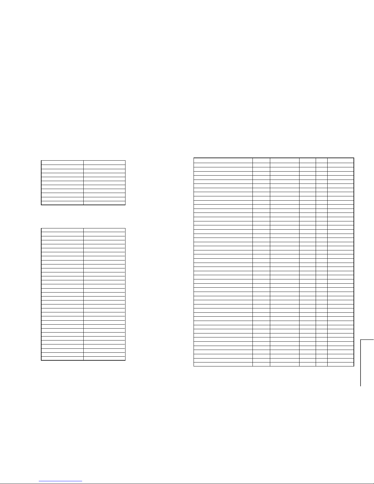
MODE USER DATA
CONTRAST MAX
COLOUR CENTER
BRIGHTNESS CENTER
TINT CENTER
SHARPNESS CENTER
WHITE TEMP STANDARD
S-VOLUME MAX
BLUE BACK OFF
C SYSTEM AUTO
S SYSTEM B/G
The flow of Mode lists as following,
* Direct Key-in Step1 Mode
RC COMMAND SERVICE-ITEM
STANDBY/ON STANDBY
TV/VIDEO NEXT SOURCE
DIGIT 0…9 DIGIT 0….9
AV1 SELECT AV1
AV2 SELECT AV2
-/-- 1/2 DIGIT ENTRY
FUNCTION FSET AGC
TIMER TSET SUB-VOL
TXT/MIX DRI-GS
PIC DRI-BS
HOLD DRI-GC
CANCEL DRI-GW
SIZE DRI-RC
REVEAL DRI-BW
RED CUT-R
GREEN CUT-G
BLUE BACK S-COR
S-SYSTEM HB
CONTRAST + SUB-CON
CONTRAST - V-LIN
COLOUR + SUB-COL
COLOUR - V-AMP
BRIGHTNESS + SUB-BRI
BRIGHTNESS - V-CENT
TINT + SUB-TINT
TINT - H-CENT
SHARPNESS + SUB-SHP
SHARPNESS - EW//
BASS + FM_LV
BASS - IGR_LV
TREBLE + IGR_STR
TREBLE - B/G_NLV
After short JA122 & JA124, and turn on the main power switch, read data from EEPROM
address 00H ~ 03H, and compare to the list below, if different, initialize the EEPROM.
Address : Data Address : Data
00H : 55H 02H : 53H
01H : 41H 03H : 36H
EEPROM ITEMS OSD DATA LENGTH
INITIAL DATA FIX/ADJ
REMARK
AGC TAKE OVER POINT AGC 0~63 14 ADJ
VERTICAL SLOPE V-LIN 0~63 32 ADJ
VERTICAL AMPLITUDE V-AMP 0~63 32 ADJ
VERTICAL SHIFT V-CENT 0~63 32 ADJ
HORIZONTAL SHIFT H-CENT 0~63 32 ADJ
HORIZONTAL SIZE H-SIZE 0~63 32 FIX NO EFFECT
HORIZONTAL PARALLELOGRAM EW// 0~63 32 FIX NO EFFECT
EAST-WEST PARABOLA/WIDTH PARA 0~63 32 FIX NO EFFECT
CORRECTION UPPER COR (U) 0~63 32 FIX NO EFFECT
CORRECTION LOWER COR (L) 0~63 32 FIX NO EFFECT
TRAPEZIUM TRAPE 0~63 32 FIX NO EFFECT
HORIZONTAL BOW HB 0~63 32 FIX NO EFFECT
S-CORRECTION S-COR 0~63 0 FIX
WHITE POINT RED STD WHITE TEMP DRI-RS 0~63 32 FIX
WHITE POINT GREEN STD WHITE TEMP DRI-GS 0~63 32 ADJ
WHITE POINT BLUE STD WHITE TEMP DRI-BS 0~63 32 ADJ
WHITE POINT RED COOL WHITE TEMP DRI-RC 0~63 25 FIX
WHITE POINT GREEN COOL WHITE TEMP DRI-GC 0~63 32 FIX (DRI-GS)-7 DATA
WHITE POINT BLUE COOL WHITE TEMP DRI-BC 0~63 32 FIX (DRI-BS)
SAME DATA
WHITE POINT RED WARM WHITE TEMP DRI-RW 0~63 32 FIX
WHITE POINT GREEN WARM WHITE TEMP DRI-GW 0~63 32 FIX (DRI-GS)-7 DATA
WHITE POINT BLUE WARM WHITE TEMP DRI-BW 0~63 32 FIX (DRI-BS)-7 DATA
MAX VOLUME SUB-VOL 0~60 60 FIX
SUB CONTRAST SUB-CON 0~63 63 FIX
SUB COLOUR SUB-COL 0~63 32 ADJ
SUB BRIGHTNESS SUB-BRI 0~63 32 ADJ
SUB TINT SUB-TINT 0~63 32 ADJ
SUB SHARPNESS SUB-SHP 0~63 32 FIX
MAX HOTEL VOLUME HTL-VOL 0~60 30 FIX *1
HOTEL PROGRAM NUMBER HTL-PRG
0~99 OR>99FOR NONE
255 FIX
BLUE BACK CONTRAST BB-CON 0~15 10 FIX
OSD RGB REFERENCE RGB 0~15 15 FIX
BLACK LEVEL OFF-SET R CUT-R 0~15 8 ADJ
BLACK LEVEL OFF-SET G C U T-G 0~15 8 ADJ
CATHODE DRIVE LEVEL CDL 0~15 0 FIX *2
Y-DELAY TIME FOR PAL(TV) [YD] DL-PT 0~15 12 FIX
Y-DELAY TIME FOR SECAM(TV) [YD] DL-ST 0~15 15 FIX
Y-DELAY TIME FOR N358 (TV) [YD] DL-3T 0~15 12 FIX
Y-DELAY TIME FOR N443 (TV) [YD] DL-4T 0~15 12 FIX
Y-DELAY TIME FOR B/W (TV) [YD] DL-TV 0~15 12 FIX
Y-DELAY TIME FOR PAL (AV) [YD] D L-PA 0~15 12 FIX
Y-DELAY TIME FOR SECAM (AV) [YD] DL-SA 0~15 15 FIX
Y-DELAY TIME FOR N358 (AV) [YD] DL-3A 0~15 12 FIX
Y-DELAY TIME FOR N443 (AV) [YD] DL-4A 0~15 12 FIX
Y-DELAY TIME FOR B/W (AV) [YD] DL-AV 0~15 12 FIX
COLOUR OFFSET (PAL) COL-OP 0~15 8 FIX
COLOUR OFFSET (SECAM) COL-OS 0~15 8 FIX
COLOUR OFFSET (NTSC358) COL-O3 0~15 4 FIX
COLOUR OFFSET (NTSC443) COL-O4 0~15 4 FIX
6
20U200, 20U250
51U200, 51U250
51U500, 51U550
6-1 6-2
NOTE ( * ) :
Fix data, please do not change without specific instruction.”
*1 : Unless customer request, or else please fix the adjustment
*2 : CDL data= ‘ 2 ‘.
*3 : Manual change to ‘ 0 ‘
*4 : Switch off AN5890 ( Manual change to ‘ 0 ‘ )
*5 : Switch on AN5891 ( Manual change to ‘ 1 ‘ )
*6 : Change FM-LV data from 15 to 21
Change IGR-LV data from 16 to 23
Change B/G-NLV data from 13 to 20
Change LOW ERR data from 35 to 20
*7 : Change to ‘1’ for NICAM and IGR model
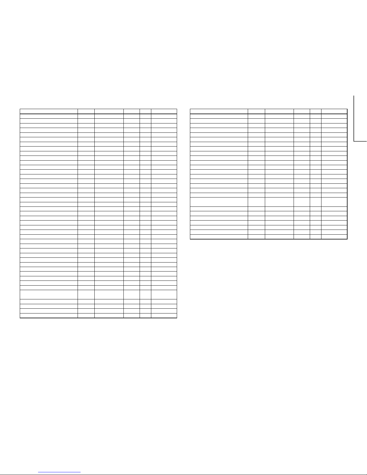
EEPROM ITEMS OSD DATA LENGTH
INITIAL DATA FIX/ADJ
REMARK
SHARPNESS OFFSET (PAL) SHP-OP 0~15 8 FIX
SHARPNESS OFFSET (SECAM) SHP-OS 0~15 4 FIX
SHARPNESS OFFSET (NTSC358) SHP-O3 0~15 12 FIX
SHARPNESS OFFSET (NTSC443) SHP-O4 0~15 8 FIX
BASS MIX FOR ANXXXX BM-ON
0(DISABLE)/1(ENABLE)
0 FIX
BASS MIX EFFECT FOR ANXXXX BM-EFF 0~3 2 FIX
AGC FOR ANXXXX AGC-ON
0(DISABLE)/1(ENABLE)
1 FIX
AGC ADJUST FOR ANXXXX AGC-ADJ 0~3 3 FIX
NICAM AGC AGC-N
0(ENABLE)/1(DISABLE)
0 FIX
NICAM AGC GAIN ADJ GAIN-N 0~31 0 FIX
FM OUTPUT LEVEL FM-LV 0~30 15 FIX *6
IGR OUTPUT LEVEL IGR-LV 0~30 16 FIX *6
NICAM OUTPUT LEVEL (B/G) BG-NLV 0~30 13 FIX *6
NICAM OUTPUT LEVEL (I) I-NLV 0~30 18 FIX
NICAM OUTPUT LEVEL (D/K) DK-NLV 0~30 13 FIX
NICAM LOWER ERROR LIMIT LOW-ERR 0~255 35 FIX *6
NICAM UPPER ERROR LIMIT UP-ERR 0~255 70 FIX
IGR STEREO R CH GAIN ADJUST IGR-STR 0~13 6 FIX
VERTICAL SCAN DISABLE VSD
0(DISABLE)/1(ENABLE)
0 FIX
BLACK STRETCH BKS
0(DISABLE)/1(ENABLE)
1 FIX
AUTOMATIC VOLUME LEVELING AVL
0(DISABLE)/1(ENABLE)
1 FIX
FAST FILTER IF-PLL FFI
0(DISABLE)/1(ENABLE)
0 FIX
ENABLE VERTICAL GUARD (RGB BLANKING) EVG
0(DISABLE)/1(ENABLE)
1 FIX ONLY BLK
EHT TRACKING MODE (HCO) EHT
0(DISABLE)/1(ENABLE)
1 FIX
OVERSCAN SWITCH OFF OSO
0(DISABLE)/1(ENABLE)
0 FIX
AUTO COLOUR LIMIT ACL
0(DISABLE)/1(ENABLE)
0 FIX
FORCED COLOUR LIMIT FCO
0(DISABLE)/1(ENABLE)
0 FIX
SOUND SYSTEM M S-M
0(DISABLE)/1(ENABLE)
0 FIX
SOUND SYSTEM DK S-DK
0(DISABLE)/1(ENABLE)
1 FIX *3
SOUND SYSTEM I S-I
0(DISABLE)/1(ENABLE)
1 FIX *3
SOUND SYSTEM BG S-BG
0(DISABLE)/1(ENABLE)
1 FIX
PLAYBACK SECAM P-SECAM
0(DISABLE)/1(ENABLE)
1 FIX *3
FE (RF) NTSC 3.58 F-N358
0(DISABLE)/1(ENABLE)
0 FIX
FE (RF) NTSC 4.43 F-N443
0(DISABLE)/1(ENABLE)
1 FIX *3
FE (RF) SECAM F-SECAM
0(DISABLE)/1(ENABLE)
1 FIX *3
VIDEO MUTE AT IDENT LOSS VMI
0(DISABLE)/1(ENABLE)
1 FIX
VIDEO MUTE AT PROGRAM/SOURCE CHANGE
VMC
0(DISABLE)/1(ENABLE)
1 FIX
HOTEL MODE HTL
0(DISABLE)/1(ENABLE)
0 FIX
REDUCED FM DEMODULATOR GAIN BTSC
0(DISABLE)/1(ENABLE)
0 FIX
FOR BTSC SIGNAL
NUMBER OF EXTERNAL AV SOURCE AV 0 FOR1 AV/1 FOR 2AV 1 FIX
FM WINDOW SELECTION FMWS
0(DISABLE)/1(ENABLE)
0 FIX
SOUND MUTE BIT 0 SM0
0(DISABLE)/1(ENABLE)
1 FIX
SOUND MUTE BIT 1 SM1 0(DISABLE)/1(ENABLE) 0 FIX
EEPROM ITEMS OSD DATA LENGTH
INITIAL DATA FIX/ADJ
REMARK
THAI LANGUAGE THA
0(DISABLE)/1(ENABLE)
0 FIX
ARABIC LANGUAGE ARA
0(DISABLE)/1(ENABLE)
1 FIX *3
MALAY LANGUAGE MAL
0(DISABLE)/1(ENABLE)
1 FIX *3
CHINESE LANGUAGE CHI
0(DISABLE)/1(ENABLE)
1 FIX *3
FRENCH LANGUAGE FRE
0(DISABLE)/1(ENABLE)
1 FIX *3
RUSSIAN LANGUAGE RUS
0(DISABLE)/1(ENABLE)
1 FIX *3
FORCED V-SYNC SLICING LEVEL FSL
0(DISABLE)/1(ENABLE)
0 FIX
SYNC OF OSD HP2
0(DISABLE)/1(ENABLE)
0 FIX
IF AGC SPEED BIT 0 AGC0
0(DISABLE)/1(ENABLE)
1 FIX
IF AGC SPEED BIT 1 AGC1
0(DISABLE)/1(ENABLE)
0 FIX
PHI-1 TIME CONSTANT (RF) FOA-FE
0(DISABLE)/1(ENABLE)
0 FIX
PHI-1 TIME CONSTANT (RF) FOB-FE
0(DISABLE)/1(ENABLE)
0 FIX
PHI-1 TIME CONSTANT (OFF AIR) FOA-AV
0(DISABLE)/1(ENABLE)
1 FIX
PHI-1 TIME CONSTANT (OFF AIR) FOB-AV
0(DISABLE)/1(ENABLE)
1 FIX
TELETEXT TXT
0(DISABLE)/1(ENABLE)
0 FIX
TELETEXT WESTERN OR EASTERN CHAR TXT-WE
0(WESTERN)/1(EASTERN)
0 FIX
TELETEXT PAN-EURO LANG TXT-EUR 0(EURO)/1(OTHER) 0 FIX
IF FREQ SELECTION IF-38.0 0(38.9)/1(38.0) 0 FIX
CHARGE PUMP CP 0(FAST TUNE)/ 0 FIX
1(MODERATE TUNE)
AN5890 PRESENT AN5890
0(DISABLE)/1(ENABLE)
1 FIX *4
AN5891 PRESENT AN5891
0(DISABLE)/1(ENABLE)
0 FIX *5
AN7396 PRESENT AN7396
0(DISABLE)/1(ENABLE)
0 FIX
NICAM DECODING ENABLED NICAM
0(DISABLE)/1(ENABLE)
0 FIX *7
IGR DECODING ENABLED IGR
0(DISABLE)/1(ENABLE)
0 FIX *7
GAME MODE ENABLED GAME
0(DISABLE)/1(ENABLE)
0 FIX
BILINGUAL BIL
0(DISABLE)/1(ENABLE)
0 FIX
7
20U200, 20U250
51U200, 51U250
51U500, 51U550
7-1 7-2
SHIPPING SETTING & CHECKING
(1)The following default data has been factory-set for the E2PROM.
(By press factory setting 3 key)
ITEMS DATA SETTING
LAST PROGRAM/CHANNEL 1
FLASHBACK PROGARM/CH 1
DIGIT 2
C-SYSTEM AUTO
S-SYSTEM B/G
SKIP OFF
AFC ON
VOLUME 1
CONTRAST 60 (MAX)
COLOUR 0 (CENTER)
BRIGHTNESS 0 (CENTER)
TINT 0 (CENTER)
SHARPNESS 0 (CENTER)
WHITE TEMP STANDARD
REMINDER TIMER In-active, "--:--"
ON TIMER In-active, "--:--"
OFF TIMER In-active, "--:--"
LAST POWER POWER-ON
LANGUAGE ENGLISH
BLUE BACK MUTE ON
HOTEL MODE OFF
0 CHANNEL SKIP ON
LAST TV/AV TV
BASS/TRE/BAL CENT
SURROUND OFF
SURROUND LEVEL CENT
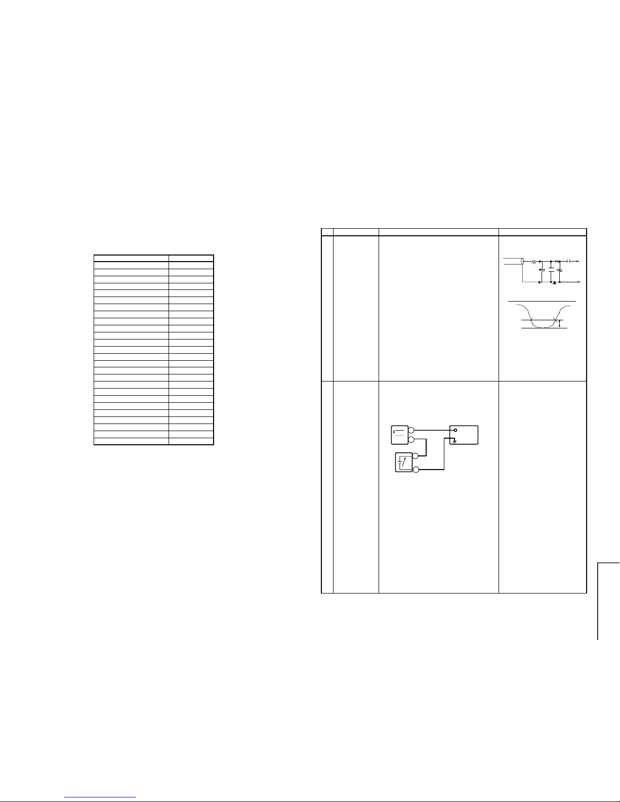
PIF ADJUSTMENT
NO. Adjustment part Adjusting procedure and conditions Waveform and others
1
Fig. 1
2 RF-AGC
TAKE OVER
POINT
ADJUSTMENT
(I2C BUS
CONTROL)
1. Receive "PAL COLOUR BAR" signal.
» Signal Strength: 57 ±1 dBµV (75 ohm open)
2. Connect the oscilloscope to TP201 (Tuner’s
AGC Terminal) as shown in Fig. 3.
3. Call "AG" mode in service mode. Adjust the
"AG" bus data to obtain the Tuner output pin
drop 0.1 V below maximum voltage .
4. Change the antenna input signal to
63~67dBµV , and make sure there is no noise .
5. Turn up the input signal to 90~95 dBµV to be
sure that there is no cross modulation beat.
Note:
For the 50 ohm signal strength
gauge, when not using 50/75
impedance adapter, signal
strength is 52 ±1 dBµV(75 ohm
open), instead of 57 ±1 dBµV
(75 ohm open).
For the 50 ohm signal strength
gauge,
Precaution:
The loss of using impedance
adapter.
» Bias box: About 4.5 V
Oscilloscope
0.1V
TV Set
Bias box
TP201+
+
–
–
Tuner IFT
(PRESET)
1. Get the tuner ready to receive the E-9 CH
signal, but with no signal input.
Adjust the PLL data.
2. Connect the sweep generator's output cable
to the tuner antenna. (RF SWEEP)
3. Adjust the sweep generator's to 80dBµV.
4. Connect the response lead (use LOW IMPEDANCE probe with wave detector; see Fig.1) to
the tuner's IF output terminal. (This terminal
must have the probe alone connected).
5. Set the RF AGC to 0 - 6 V with no saturation
with the waveform.
6. Adjust the tuner IF coil to obtain the waveform
as shown in Fig. 2.
Note:Be sure to keep the tuner cover in
position during this adjustment.
E-9 CH
P C
10k
100k
1n60
75ohm
IF OUT
-1.5+/-0.8dB
1000p
Oscilloscope
Fig. 2
Fig. 3
Note: After pressing MODEL setting. 0 channel will be skipped.
8
20U200, 20U250
51U200, 51U250
51U500, 51U550
8-1 8-2
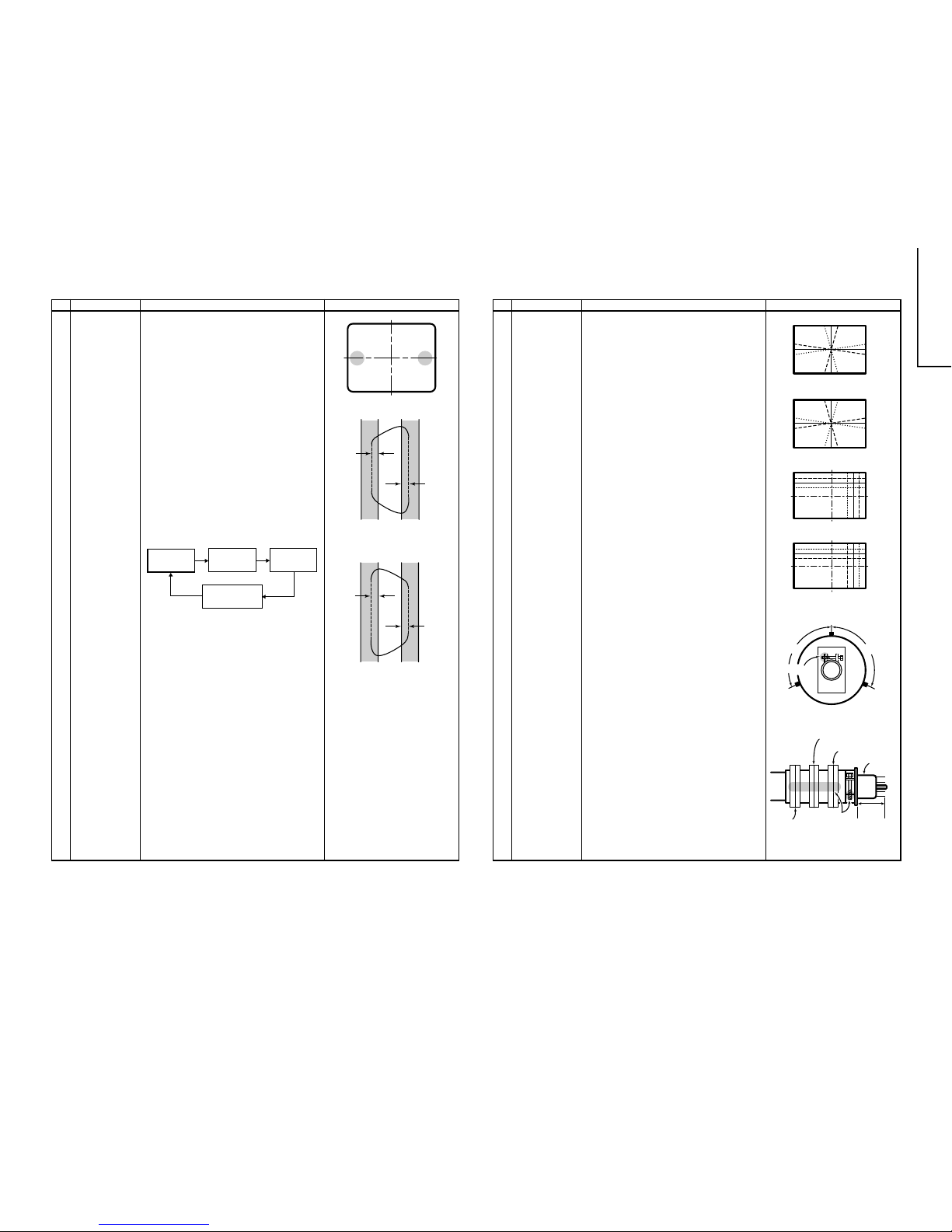
PURITY ADJUSTMENT
NO. Adjustment par t Adjusting procedure and conditions Waveform and others
1
PURITY ADJ. 1. Receive the GREEN-ONLY signal. Adjust the
beam current to about 700 mA.
2. Degauss the CRT. Maintain the purity magnet
at the zero magnetic field and keep the static
convergence roughly adjusted.
3. Observe the points a, b as shown in Fig. 4-1
through the microscope. Adjust the landing to
the rank A requirements.
4. Orient the raster rotation to 0 eastward.
5. Tighten up the deflection coil screws.
» Tightening torque: 108 ± 20 N (11 ±2 kgf)
6. Make sure the CRT corners landing meet the
A rank requirements. If not, stick the magnet
sheet to correct it.
Note: This adjustment must be done after
warming up the unit for 30 minutes
or longer with a beam current over
700 µA.
* For the f ollowing colours press R/C RGB k ey
to change.
* Press R/C RGB key for a sec-
ond in NORMAL MODE, the
colour will change to RGB mono
colour mode.
a
b
A
B
A
B
A = B
A = B
Rank "A"
(on the right of the CRT)
Rank "A"
(on the left of the CRT)
Red-only
Green-only
Blue-only
Signal-colour
screen cleared
Fig. 4-1
Fig. 4-2
Fig. 4-3
RGB
BGR
R
G
B
R
G
B
B
G
R
B
G
R
RGB
BGR
Lacquer
Wedge "a"
Wedge
"b"
Wedge
"c"
About
100°
About
100°
4-pole magnet
6-pole magnet
CRT neck
20mm
Lacquer
Purity magnet
CONVERGENCE ADJUSTMENT
NO. Adjustment part Adjusting procedure and conditions Waveform and others
1 CONVERGENC
ADJ.
(To be done
after the purity
adjustment.)
1. Receive the "Crosshatch Pattern" signal.
2. Using the remote controller, call NORMAL
mode.
Static Convergence
1. Turn the 4-pole magnet to a proper opening
angle in order to superpose the blue and red
colours.
2. Turn the 6-pole magnet to a proper opening
angle in order to superpose the green colour
over the blue and red colours.
Dynamic Convergence
1. Adjust the convergence on the fringes of the
screen in the following steps.
a) Fig. 5-1: Drive the wedge at point "a" and
swing the deflection coil upward.
b) Fig. 5-2: Drive the wedge at points "b"
and "c", and swing the deflection coil
downward.
c) Fig. 5-3: Drive the "c" wedge deeper and
swing the deflection coil rightward.
d) Fig. 5-4: Drive the "b" wedge deeper and
swing the deflection coil leftward.
2. Fix all the wedges on the CRT and apply glass
tape over them.
3. Apply lacquer to the deflection yok e lock screw ,
magnet unit (purity, 4-pole, 6-pole magnets)
and magnet unit lock screw.
Finally received the Red-only and Blue-only
signals to make sure there is no other colours
on the screen.
Fig. 5-2
Fig. 5-1
Fig. 5-3
Fig. 5-4
Fig. 5-5
Fig. 5-6
9
20U200, 20U250
51U200, 51U250
51U500, 51U550
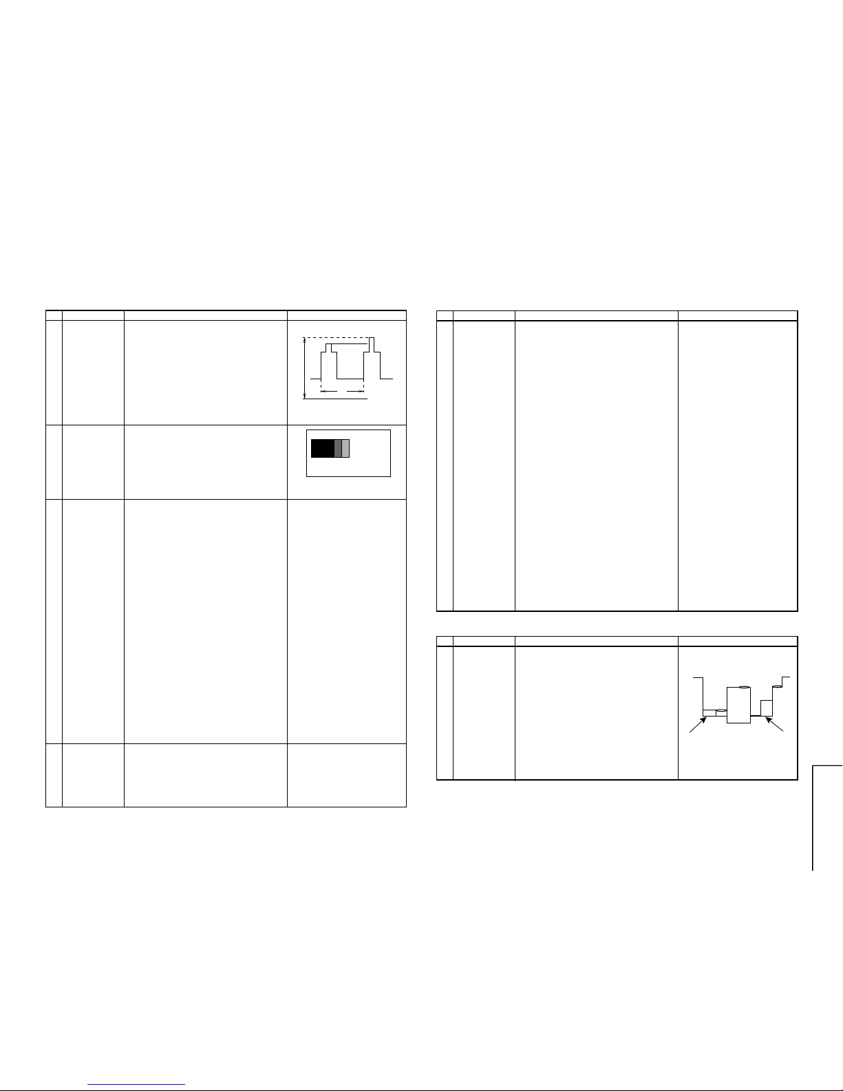
9-1 9-2
1. Call "SUB-BRI" in service mode. (Receive
Crosshatch pattern with 5 black level windows)
2. Adjust the "SUB BRIGHT" bus data in order
that the line 1, 2 and 3 have the same darkness
wherelse line 4 is slightly brighter than line 1,
2 and 3 and finally line 5 will be the brighter
than line 4.
1. Switch TV to VIDEO mode, BLUE BACK OFF
with NO VIDEO signal.
2. Press R/C to set Picture Normal condition.
3. Connect the oscilloscope to Red OUT from
IC801. (TP851)
Range : 1 V/Div (DC)
Sweep : 5 msec/Div
4. Adjust SCREEN VR, so that the tip of signal
reach 3.0 ±0.1 Vdc.
CUT-OFF, B ACKGROUND AND SUB-CONTRAST ADJUSTMENT
NO. Adjustment part Adjusting procedure and conditions Waveform and others
1
2 SUB-
BRIGHTNESS
ADJUSMENT
(I
2
C BUS
CONTROL)
1, 2 and 3 are in same black level.
CRT CUTOFF
ADJUSTMENT
(I
2
C BUS
CONTROL)
Fig. 6
3 WHITE
BALANCE
SERVICE
MODE ADJ.
(I2C BUS
CONTROL)
1. Receive the "Monoscope Pattern with BURST"
signal.
2. Press R/C to set Picture NORMAL condition.
3. Connect the DC miliammeter between TP602
(-) and TP603 (+).
4. Check Beam current should be around 1,100 µA.
5. Set it to service mode and adjust the " DRIGS" & "DRI-BS" data to have a colour
temperature of 12,300°K. (Note.)
6. Receive "White" pattern, with BURST Signal, and
set Brightness Y by generator, to** 10 cd/m
2
(Minolta CA-100) by reducing Luminate Y signal.
7. Adjust "CUT -R" & "CUT-G" to get 12,300°K. Then
go back normal mode (High Bright)** to check
colour temperature. If out of range, back to 1.
Note: This adjustment must be done after
warming up the unit for 30 minutes
or longer with a beam current over
700µA).
* Adjust DRI-GC/GW, DRI-BC/BW as following
data after finishing DRI-GS and DRI-BS.
DRI-GC/GW DATA="DRI-GS" -7 DATA
DRI-BC=DRI-BS
DRI-BW DATA="DRI-BS" -7 DATA
** Low=10 cd/m
2
: High=120 cd/m
2
Refer to Page 7.
* 12,300°K X : 0.272
Y : 0.275
(MINOLTA COLOUR ANALYZER
CA-100)
(Note): Above Data can be UP/
DOWN by Volume key.
4 Maximum
beam check
1. Receive the "Monoscope Pattern" signal.
2. Press R/C to set Picture NORMAL condition.
3. Connect the DC miliammeter between TP603
(+) and TP602 (–).
(Full Scale: 3 mA Range)
4. Beam current must be within 1,100 ±100 µA.
1 V
3.0Vdc
0
1 2 3 4 5
Fig. 7
HORIZONTAL, VERTICAL, DEFLECTION LOOP AND FOCUS ADJUSTMENT
NO. Adjustment part Adjusting procedure and conditions Waveform and others
1
2
3
4
5
6
V-SLOPE
(I
2
C BUS
CONTROL)
V-SHIFT
(I
2
C BUS
CONTROL
V-AMP
(I
2
C BUS
CONTROL)
S-CORRECTION (I
2
C
BUS CONTROL)
H-SHIFT (50)
(H - CENTER)
(I
2
C BUS
CONTROL)
FOCUS
1. Receive "PAL 50Hz Monoscope Pattern"
Signal.
2. Call the "V-LIN" mode.
3. Increase or decrease "V-LIN" by Volume key till
the horizontal line in the center of monoscope is
just at the position where the blanking starts.
1. Call the "V-CENT" mode.
2. Increase or decrease "V -CENT" b y V olume k e y
till the picture is centered.
1. Call the "V-AMP" mode.
2. Increase or decrease "V- AMP" by Volume k e y
to set overscan of 8.5% typical.
Adjustment Spec 8.5% range +1% -0%.
FIXED DA TA, NO NEED TO ADJUST.
1. Call the "H-CENT" mode.
2. Increase or decrease "H-CENT" by V olume ke y
to center the picture horizontal.
1. Receive the "Monoscope Pattern" signal.
2. Press R/C to set Picture NORMAL condition.
3. Adjust the focus control to get the best
focusing.
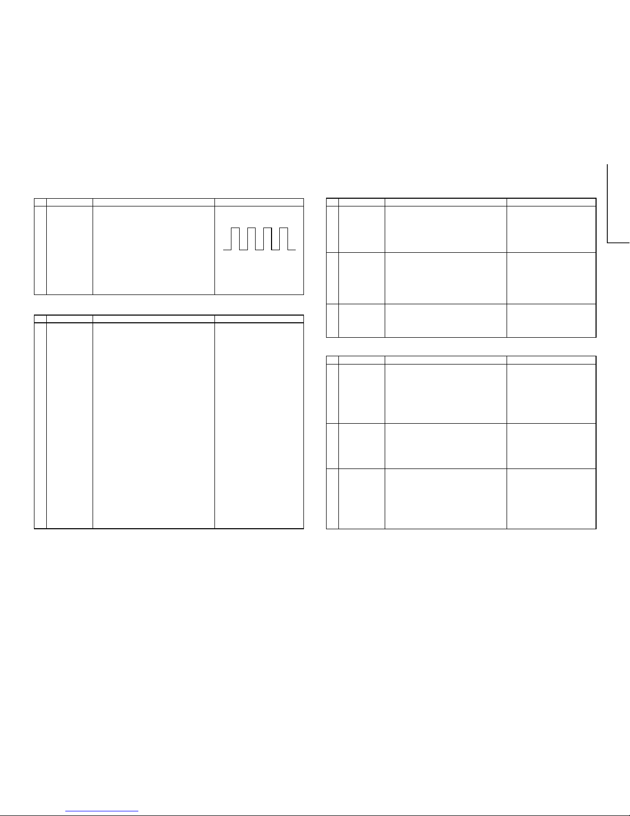
PAL CHROMA ADJUSTMENT
NO. Adjustment part Adjusting procedure and conditions Waveform and others
1
SUB COLOUR
(I
2
C BUS
CONTROL)
1. Receive the "PAL Colour Bar" signal.
2. Press R/C to set Picture Normal condition.
3. Connect the oscilloscope to Red cathode
(Between C881 and R885).
» Range : 20 V/div. (AC) (Using 10:1 probe)
» Sweep time : 10 µsec/div.
4. Using the R/C call "SUB COL" in SERVICE
mode. Adjust SUB COLOUR bus data, so that
the 75% White & Red portions of PAL Colour
Bar be at the same level shown as Fig. 8.
5. Clear the SERVICE mode.
Cy
G
B
W
Y 100%W
75%
Mg R
Fig. 8
10
20U200, 20U250
51U200, 51U250
51U500, 51U550
10-1 10-2
NTSC CHROMA ADJUSTMENT
NO. Adjustment par t Adjusting procedure and conditions Waveform and others
1 SUB-TINT (I
2
C
BUS
CONTROL)
1. Receive the "NTSC3.58 Colour Bar" signal
through AV in.
2. Connect the oscilloscope to TP853 (Pin (5) of
P882) BLUE-OUT.
» Range : 100mV/div . (A C)(Use Probe 10:1)
» Sweep time: 10 µsec/div.
3. Call the "SUB-TINT" mode in service mode.
Adjust the "SUB-TINT" bus data to obtain the
waveform shown as Fig. 9.
4. Clear the SERVICE mode.
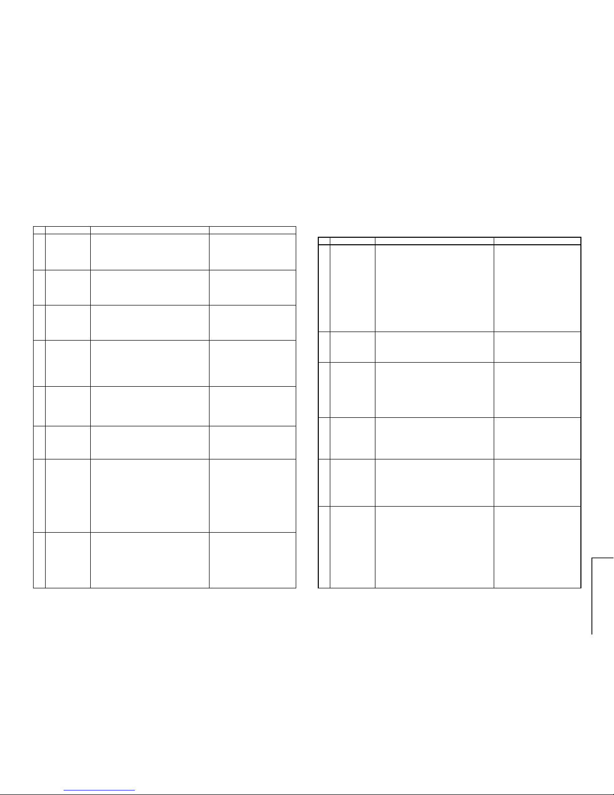
PROTECTOR OPERATION CHECKING
NO. Adjustment par t Adjusting procedure and conditions Waveform and others
1 BEAM
Protector
1. Receive "Monoscope Pattern" signal.
2. Set CONTRAST MAX.
3. Set BRIGHT MAX.
4. During the Collector & Emitter of Q883/5/7
short, make sure the protector ON and switch
to standby mode.
* Select one of Q883/5/7 to do each
short test.
2 H, V Protector 1. Receive "Monoscope Pattern" signal.
2. Connect output of Bias Box to D607 cathode
(R606 side).
3. Set voltage of Bias Box to 18V and make sure
the protector is not work.
4. Set voltage of Bias Box to 27V, and make sure
the protector is work.
A/V INPUT AND OUTPUT CHECKING
NO. Adjustment par t Adjusting procedure and conditions Waveform and others
1 VIDEO AND
AUDIO OUTPUT Check
1. Receive the "PAL Colour Bar" signal (100%
White Color Bar, Sound 400 Hz 100% Mod.)
2. Terminate the Video output with a 75 ohm impedance. Make sure the output is as specified
(1.0 Vp-p ±3 dB).
3. Terminate the Audio output with a 10k ohm impedance. Make sure the output is as specified
(1.76 Vp-p ±3 dB).
2 VIDEO AND
AUDIO INPUT
Check
1. Using the TV/AV key on the remote controller,
make sure that the modes change in order of
TV , A V1, A V2 & TV again and the video & audio
output are according to the input terminal for
each mode.
3 Other
Protectors
1. Once finish rectified Electrolytic Capacitor short
testing in +B line, check all possible damaged
components on +B line.
(Use random selected set for inspection)
WYCy G Mg R
B
Fig. 9
SIF (NICAM/IGR) ADJUSTMENT (51R500/550 ONLY)
NO. Adjustment par t Adjusting procedure and conditions Waveform and others
1 VCO COIL
T2300
1. Receive "PAL Colour Bar" signal.
(Set AFT OFF, 203.25 MHz frequency)
2. Connect DC Voltmeter to Pin (1) of P2301
(Main Unit). (TP2300 in NICAM/IGR Unit)
3. Check and turn T2300 counter-clockwise (Left)
to 0V and then turn it clockwise (Right) until
TP2300 become 5V.After that, turn T2300
counter-clockwise (Left) until TP2300 become
2.5 ± 0.1 Vdc.
* UNIT BOARD ADJUSTMENT
Vcc 5.0 ± 0.1 Vdc
IF Input Frequency 38.9 MHz ± 10 KHz
Adjust T2300 until TP2300 (NICAM/IGR Unit)
become 2.5 ± 0.1 Vdc.
Check after assembly NICAM Board
Test Point: Pin (1) of P2301 (Main Unit)
Preset selected reception frequency (AFT
OFF)
Check Voltage 2.5 ± 1.0 Vdc.
Precaution: The Vcc, f0 and other factors are
considered in the unit board of the
1.0 V tolerance which differ from the
adjustment accuracy.
3 SUBWOOFER
OUTPUT
Check
1. Receive "PAL Colour Bar" signal ( Sound
400Hz, 100% Mod.)
2. Set the sound output to 2 Vrms by volume key.
(Speaker Impedance: 8 Ohm, Sound Output:
500mW)
3. Terminate the "Sub - Woofer" output with a 22
kΩ impedance.Make sure that the output is
5.6Vp-p ± 3dB.
11
20U200, 20U250
51U200, 51U250
51U500, 51U550
11-1 11-2
FUNCTION OPERATION CHECKING (VIDEO AND AUDIO)
NO. Adjustment part Adjusting procedure and conditions Waveform and others
1
2 COLOUR Key 1. Receive "Colour Bar" signal.
2. Set PICTURE MENU to select COLOUR.
3. Press Volume Up/Down key to check whether
the COLOUR effect is OK or not.
CONTRAST
Key
1. Receive "Monoscope Pattern" signal.
2. Set PICTURE MENU to select CONTRAST.
3. Press Volume Up/Down key to check whether
the CONTRAST effect is OK or not.
3 BRIGHTNESS
Key
1. Receive "Monoscope Pattern" signal.
2. Set PICTURE MENU to select BRIGHTNESS.
3. Press Volume Up/Down key to check whether
the BRIGHTNESS effect is OK or not
4 TINT key 1. Receive the "NTSC Colour Bar" signal through
AV in.
2. Set PICTURE MENU to select TINT.
3. Press Volume Up/Down key to check TINT, UP
for GREEN direction and DOWN for PURPLE
direction whether is OK or not.
5 SHARPNESS
Key
1. Receive "Monoscope Pattern" signal.
2. Set PICTURE MENU to select SHARPNESS.
3. Press Volume Up/Down key to check whether
the SHARPNESS effect is OK or not.
6 CH DISPLAY
COLOUR
1. All Ch (1~99) will have an OSD display of the
channel number in green colour under AFT ON
condition.
7 NORMAL Key 1. Once in PICTURE / SOUND MENU and the
NORMAL key is pressed, all the settings will
be present to normal setting. (Normal setting
value for every mode).
CONTRAST : MAX TREBLE : CENTER
COLOUR : CENTER BASS : CENTER
BRIGHTNESS
:CENTER SURROUND :OFF
TINT :CENTER
SURROUND LEVEL
: CENTER
SHARPNESS
:CENTER BALANCE : CENTER
8 WHITE TEMP 1. Receive "Monoscope P attern" signal.
2. Set PICTURE MENU to select WHITE TEMP.
3. Press Volume Up/Down key to check WHITE
TEMP Option, STANDARD:
NORMAL SETTING, WARM for more
REDDISH direction changing, COOL for more
BLUISH direction changing.
FUNCTION OPERATION CHECKING (VIDEO AND AUDIO)
(Continued)
NO. Adjustment part Adjusting procedure and conditions Waveform and others
9
COLOUR
SYSTEM
1. Receive the "PAL COLOUR BAR" signal, press
the COLOUR SYSTEM key to select modes
except P AL, check the COLOUR is not working
properly. Then, select the "PAL" mode. Check
again its colour so that it is working properly.
2. Receive "NTSC 4.43/3.58 COLOUR BAR" signal thru AV, press COLOUR SYSTEM key to
select modes except N4.43/3.58, check the
COLOUR is not working properly. Then, select
the "NTSC 4.43/3.58" mode. Check again its
colour so that it is working properly.
10 SOUND
SYSTEM
1. Receive "PAL-B/G" signal, check the sound
output is working properly or not.
11 NOISE MUTE
CHECKING
1. Receive "PAL COLOUR BAR" signal.
2. Turn up the volume control to maximum, make
sure the sound is heard from the speakers.
Then put the unit in no signal state.
3. Check the sound mute is effective.
4. Finally turn sound level of CTV to minimum.
12 OSD
LANGUAGE
QUANTITY
CHECK
Check OSD LANGUAGE quantity and type.
13 SOUND
CONTROL
(BASS/TRE/
BAL)
1. Receive "Monoscope Pattern" signal.
2. Set SOUND MENU to select BASS/TRE/BAL.
3. Select each item, and press Volume Up/Down
Key to check the sound effect.
14 SURROUND
FUNCTION
CHECKING
1. Receive STEREO Music signal thru AV.
2. Press SURROUND Key to select following
mode
SURROUND OFF
↓
SURROUND 1
(Check SURROUND sound effect)
Check the level of SURROUND 1 effect by
increasing and decreasing the level control
3. Receive MONO Music signal and press
SURROUND Key to select following mode.
SURROUND 2
(Check MONO sound effect)
12
20U200, 20U250
51U200, 51U250
51U500, 51U550
12-1 12-2
FUNCTION OPERATION CHECKING (VIDEO AND AUDIO)
(Continued)
NO. Adjustment part Adjusting procedure and conditions Waveform and others
15
OTHER
(NICAM/IGR/
TEXT)
1. Check Normal operation of each model of
different features.
Model
NICAM
IGR TEXT
20U200/250, 51U200/250 X X X
51U500/550 B/G B/G X
HEADPHONE JACK CHECKING
NO. Adjustment par t Adjusting procedure and conditions Waveform and others
1
HEADPHONE
OUTPUT
CHECKING
1. Receive PAL Colour Bar with SOUND 400Hz,
100% MODULATION (± 50kHz Dev)
2. Maximum volume, and check the headphone
output with 400Hz sound and no sound out
from speaker.
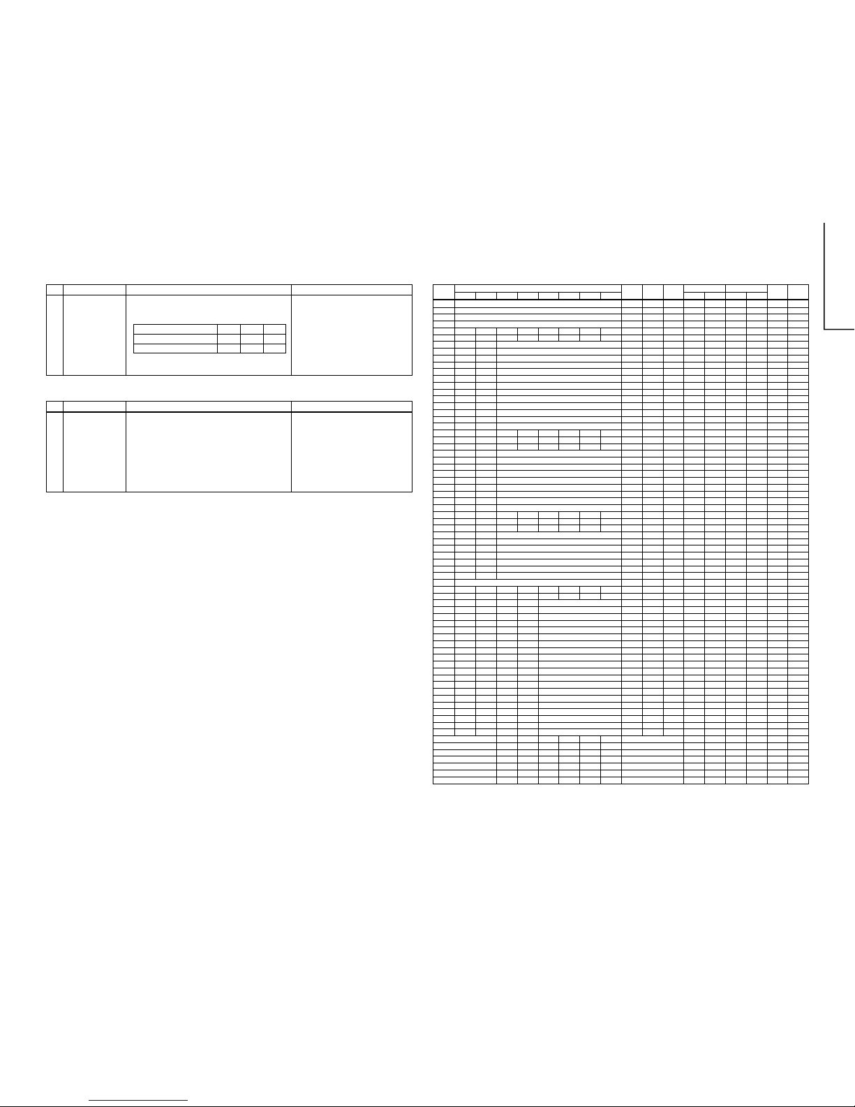
MEMORY MAP
ADDRESS
DATA
MICON EEPROM EEPROM CHASSIS CTV FINAL
LAST INTIAL
(HEX)
D7 D6 D5 D4 D3 D2 D1 D0
DEFAULT RANGE
WRITE (CPU)
CHECK DATA CHECK TYPE CHECK DATA CHECK TYPE
SETTING DATA
REMARK
00 PASS WORD 55 00-FF
01 PASS WORD 41 00-FF
02 PASS WORD 53 00-FF
03 PASS WORD 36 00-FF
04
05
06 AGC TAKE-OVER 0E 00-3F
07 V-SLOPE 20 00-3F
08 V-AMPLITUDE 20 00-3F
09 V-CENTER 20 00-3F
0A H-CENTER 20 00-3F
0B H-SIZE 20 00-3F
0C EW-PARALLELOGRAM 20 00-3F
0D EW -PARABOLA/WIDTH 20 00-3F
0E EW-UPPER CORNER 20 00-3F
0F EW-LOWER CORNER 20 00-3F
10 EW-TRAPEZIUM 20 00-3F
11 HORIZONTAL-BOW 20 00-3F
12 S-CORRECTION 00 00-3F
13
14
15
16 DRIVE-R (STANDARD) 20 00-3F
17 DRIVE-G (STANDARD) 20 00-3F
18 DRIVE-B (STANDARD) 20 00-3F
19 DRIVE-R (WARM) 20 00-3F
1A DRIVE-G (WARM) 20 00-3F
1B DRIVE-B (WARM) 20 00-3F
1C DRIVE-R (COOL) 19 00-3F
1D DRIVE-G (COOL) 20 00-3F
1E DRIVE-B (COOL) 20 00-3F
1F
20
21
22 SUB-VOLUME 3C 00-3C
23 SUB-CONTRAST 3F 00-3F
24 SUB-COLOUR 20 00-3F
25 SUB-BRIGHTNESS 20 00-3F
26 SUB-TINT 20 00-3F
27 SUB-SHARPNESS 20 00-3F
28 HTL-VOLUME 20 00-3C
29 HTL-PROGRAM NUMBER FF 00-FF
2A
2B
2C BLUE BACK CONTRAST 0A 00-0F
2D OSD-REFERENCE 0F 00-0F
2E CUTOFF LEVEL -OFFSET R 08 00-0F
2F CUTOFF LEVEL -OFFSET G 08 00-0F
30 CATHODE DRIVE LEVEL 00 00-0F
31 Y-DELAY (TV PAL) 0C 00-0F
32 Y-DELAY (TV SECAM) 0F 00-0F
33 Y-DELAY (TV N358) 0C 00-0F
34 Y-DELAY (TV N443) 0C 00-0F
35 Y-DELAY (TV BW) 0C 00-0F
36 Y-DELAY (AV PAL) 0C 00-0F
37 Y-DELAY (AV SECAM) 0F 00-0F
38 Y-DELAY (AV N358) 0C 00-0F
39 Y-DELAY (AV N443) 0C 00-0F
3A Y-DELAY (AV BW) 0C 00-0F
3B COLOUR-OFFSET (PAL) 08 00-0F
3C COLOUR-OFFSET (SECAM) 08 00-0F
3D COLOUR-OFFSET (N358) 04 00-0F
3E COLOUR-OFFSET (N443) 04 00-0F
3F SHARPNESS-OFFSET (P AL) 08 00-0F
MODEL MODEL
LETTER NO. LETTER NO.
13
20U200, 20U250
51U200, 51U250
51U500, 51U550
13-1 13-2
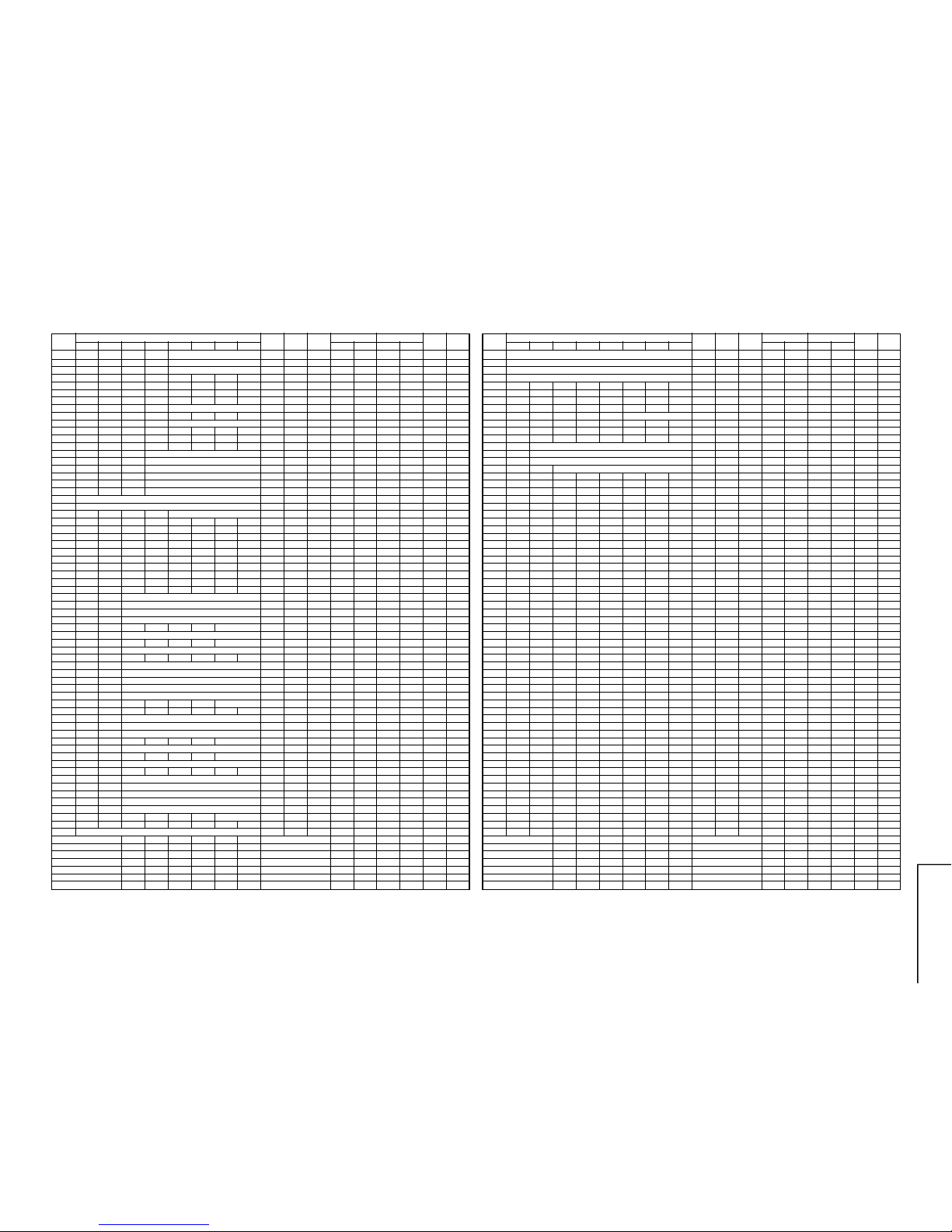
80 FAVOURITE PROGRAM RED 0A 00-FF
81 FAV OURITE PROGRAM GREEN 14 00-FF
82 FAVOURITE PROGRAM YELLOW 1E 00-FF
83 FAVOURITE PROGRAM CYAN 28 00-FF
84 POWER
85 B_BACK
86 POWER 01 00-01
87 B_BACK 00 00-01
88 LANGUAGE 00 00-06
89 DIGIT 80 00-01
8A
8B
8C ON TIMER 00 00-4D
8D OFF TIMER 00 00-4D
8E REMINDER 00 00-4D
8F FADE IN VOLUME FF 00-FF
90 TMR_FLAG 00 00-01
91
92
93 SKIP 0 SKIP 1 SKIP 2 SKIP 3 SKIP 4 SKIP 5 SKIP 6 SKIP 7 80 00-FF
94 SKIP 8 SKIP 9 SKIP 10 SKIP 11 SKIP 12 SKIP 13 SKIP 14 SKIP 15 00 00-FF
95 SKIP 16 SKIP 17 SKIP 18 SKIP 19 SKIP 20 SKIP 21 SKIP 22 SKIP 23 00 00-FF
96 SKIP 24 SKIP 25 SKIP 26 SKIP 27 SKIP 28 SKIP 29 SKIP 30 SKIP 31 00 00-FF
97 SKIP 32 SKIP 33 SKIP 34 SKIP 35 SKIP 36 SKIP 37 SKIP 38 SKIP 39 00 00-FF
98 SKIP 40 SKIP 41 SKIP 42 SKIP 43 SKIP 44 SKIP 45 SKIP 46 SKIP 47 00 00-FF
99 SKIP 48 SKIP 49 SKIP 50 SKIP 51 SKIP 52 SKIP 53 SKIP 54 SKIP 55 00 00-FF
9A SKIP 56 SKIP 57 SKIP 58 SKIP 59 SKIP 60 SKIP 61 SKIP 62 SKIP 63 00 00-FF
9B SKIP 64 SKIP 65 SKIP 66 SKIP 67 SKIP 68 SKIP 69 SKIP 70 SKIP 71 00 00-FF
9C SKIP 72 SKIP 73 SKIP 74 SKIP 75 SKIP 76 SKIP 77 SKIP 78 SKIP 79 00 00-FF
9D SKIP 80 SKIP 81 SKIP 82 SKIP 83 SKIP 84 SKIP 85 SKIP 86 SKIP 87 00 00-FF
9E SKIP 88 SKIP 89 SKIP 90 SKIP 91 SKIP 92 SKIP 93 SKIP 94 SKIP 95 00 00-FF
9F SKIP 96 SKIP 97 SKIP 98 SKIP 99 00 00-FF
A0
A1
A2 IGR 0 IGR 1 IGR 2 IGR 3 IGR 4 IGR 5 IGR 6 IGR 7 FF 00-FF
A3 IGR 8 IGR 9 IGR 10 IGR 11 IGR 12 IGR 13 IGR 14 IGR 15 FF 00-FF
A4 IGR 16 IGR 17 IGR 18 IGR 19 IGR 20 IGR 21 IGR 22 IGR 23 FF 00-FF
A5 IGR 24 IGR 25 IGR 26 IGR 27 IGR 28 IGR 29 IGR 30 IGR 31 FF 00-FF
A6 IGR 32 IGR 33 IGR 34 IGR 35 IGR 36 IGR 37 IGR 38 IGR 39 FF 00-FF
A7 IGR 40 IGR 41 IGR 42 IGR 43 IGR 44 IGR 45 IGR 46 IGR 47 FF 00-FF
A8 IGR 48 IGR 49 IGR 50 IGR 51 IGR 52 IGR 53 IGR 54 IGR 55 FF 00-FF
A9 IGR 56 IGR 57 IGR 58 IGR 59 IGR 60 IGR 61 IGR 62 IGR 63 FF 00-FF
AA IGR 64 IGR 65 IGR 66 IGR 67 IGR 68 IGR 69 IGR 70 IGR 71 FF 00-FF
AB IGR 72 IGR 73 IGR 74 IGR 75 IGR 76 IGR 77 IGR 78 IGR 79 FF 00-FF
AC IGR 80 IGR 81 IGR 82 IGR 83 IGR 84 IGR 85 IGR 86 IGR 87 FF 00-FF
AD IGR 88 IGR 89 IGR 90 IGR 91 IGR 92 IGR 93 IGR 94 IGR 95 FF 00-FF
AE IGR 96 IGR 97 IGR 98 IGR 99 FF 00-FF
AF
B0
B1 NICAM 0 NICAM 1 NICAM 2 NICAM 3 NICAM 4 NICAM 5 NICAM 6 NICAM 7 FF 00-FF
B2 NICAM 8 NICAM 9 NICAM 10 NICAM 11 NICAM 12 NICAM 13 NICAM 14 NICAM 15 FF 00-FF
B3 NICAM 16 NICAM 17 NICAM 18 NICAM 19 NICAM 20 NICAM 21 NICAM 22 NICAM 23 FF 00-FF
B4 NICAM 24 NICAM 25 NICAM 26 NICAM 27 NICAM 28 NICAM 29 NICAM 30 NICAM 31 FF 00-FF
B5 NICAM 32 NICAM 33 NICAM 34 NICAM 35 NICAM 36 NICAM 37 NICAM 38 NICAM 39 FF 00-FF
B6 NICAM 40 NICAM 41 NICAM 42 NICAM 43 NICAM 44 NICAM 45 NICAM 46 NICAM 47 FF 00-FF
B7 NICAM 48 NICAM 49 NICAM 50 NICAM 51 NICAM 52 NICAM 53 NICAM 54 NICAM 55 FF 00-FF
B8 NICAM 56 NICAM 57 NICAM 58 NICAM 59 NICAM 60 NICAM 61 NICAM 62 NICAM 63 FF 00-FF
B9 NICAM 64 NICAM 65 NICAM 66 NICAM 67 NICAM 68 NICAM 69 NICAM 70 NICAM 71 FF 00-FF
BA NICAM 72 NICAM 73 NICAM 74 NICAM 75 NICAM 76 NICAM 77 NICAM 78 NICAM 79 FF 00-FF
BB NICAM 80 NICAM 81 NICAM 82 NICAM 83 NICAM 84 NICAM 85 NICAM 86 NICAM 87 FF 00-FF
BC NICAM 88 NICAM 89 NICAM 90 NICAM 91 NICAM 92 NICAM 93 NICAM 94 NICAM 95 FF 00-FF
BD NICAM 96 NICAM 97 NICAM 98 NICAM 99 FF 00-FF
BE
BF
MODEL MODEL
LETTER NO. LETTER NO.
40 SHARPNESS-OFFSET (SECAM) 04 00-0F
41 SHARPNESS-OFFSET (N358) 0C 00-0F
42 SHARPNESS-OFFSET (N443) 08 00-0F
43
44
45
46 BM-ON 00 00-01
47 BM-EFFECT 02 00-0F
48 AGC-ON 01 00-01
49 AGC ADJUST 03 00-0F
4A
4B
4C AGC-N 00 00-01
4D GAIN-N 00 00-1F
4E FM OUTPUT LEVEL 0F 00-1E
4F IGR OUTPUT LEVEL 10 00-1E
50 NICAM OUTPUT LEVEL (B/G) 0D 00-1E
51 NICAM OUTPUT LEVEL (I) 12 00-1E
52 NICAM OUTPUT LEVEL (D/K) 0D 00-1E
53 NICAM LOWER ERROR LIMIT 23 00-FF
54 NICAM UPPER ERROR LIMIT 46 00-FF
55 IGR STEREO R CH GAIN ADJ. 06 00-0F
56 0A 00-FF
57 14 00-FF
58 OP_FCO OP_ACL OP_OSO OP_EHT OP_EVG OP_FFI OP_AVL OP_BKS 1B 00-FF
59
OP_FSECAM
OP_FN443 OP_F358
OP_PSECAM
OP_S_BG OP_S_I OP_S_DK OP_S_M DE 00-FF
5A OP_SM1 OP_SM0 OP_FMWS OP_AV OP_BTSC OP_HTL OP_VMC OP_VMI 53 00-FF
5B OP_HP2 OP_FSL OP_RUS OP_FRE OP_CHI OP_MAL OP_ARA OP_THA 3E 00-FF
5C
OP_TXT_WE
OP_TXT
OP_FOB_AV OP_FOA_AV OP_FOB_FE OP_FOA_FE
OP_AGC1 OP_AGC0 31 00-FF
5D OP_IGR OP_NICAM
OP_AN7396 OP_AN5891 OP_AN5890
OP_CP OP_IF38_0
OP_TXT_EU
08 00-FF
5E OP_GAME 00 00-01
5F
60 LAST VOLUME 01 00-3C
61 LAST BALANCE 1E 00-3C
62 LAST BASS 1E 00-3C
63 LAST TREBLE 1E 00-3C
64 LAST SURR ON/OFF 00 00-02
65 LAST SURROUND LEVEL 1E 00-3C
66 LAST SPAT ON/OFF 00 00-02
67 LAST SPATIALIZER LEVEL 1E 00-3C
68
69 LAST CONTRAST 3C 00-3C
6A LAST COLOUR 1E 00-3C
6B LAST BRIGHTNESS 1E 00-3C
6C LAST TINT 1E 00-3C
6D LAST SHARPNESS 1E 00-3C
6E LAST WHITE_TEMP 00 00-02
6F
70 LAST BALANCE-G 1E 00-3C
* 71 LAST BASS-G 1E 00-3C
72 LAST TREBLE-G 1E 00-3C
73 LAST SURR ON/OFF-G 00 00-02
74 LAST SURROUND LEVEL-G 1E 00-3C
75 LAST SPAT ON/OFF-G 00 00-02
76 LAST SPATIALIZER LEVEL-G 1E 00-3C
77
78 LAST CONTRAST-G 3C 00-3C
79 LAST COLOUR-G 1E 00-3C
7A LAST BRIGHTNESS-G 1E 00-3C
7B LAST TINT -G 1E 00-3C
7C LAST SHARPNESS-G 1E 00-3C
7D LAST WHITE_TEMP-G 00 00-02
7E
7F LAST PROGRAM/SOURCE 01 00-FF
MODEL MODEL
LETTER NO. LETTER NO.
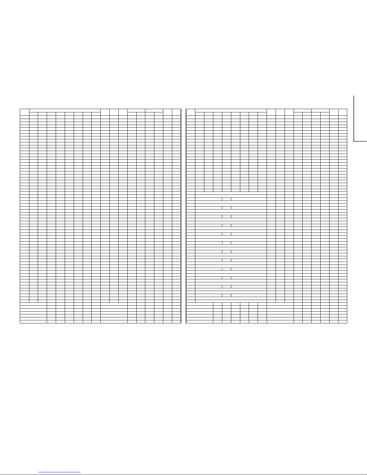
ADDRESS
DATA
MICON EEPROM EEPROM CHASSIS CTV FINAL
LAST INTIAL
(HEX)
D7 D6 D5 D4 D3 D2 D1 D0
DEFAULT RANGE
WRITE (CPU)
CHECK DATA CHECK TYPE CHECK DATA CHECK TYPE
SETTING DATA
REMARK
ADDRESS
DATA
MICON EEPROM EEPROM CHASSIS CTV FINAL
LAST INTIAL
(HEX)
D7 D6 D5 D4 D3 D2 D1 D0
DEFAULT RANGE
WRITE (CPU)
CHECK DATA CHECK TYPE CHECK DATA CHECK TYPE
SETTING DATA
REMARK
14
20U200, 20U250
51U200, 51U250
51U500, 51U550
14-1 14-2
100 NIC_3D 32 NIC_3D 33 NIC_3D 34 NIC_3D 35 NIC_3D 36 NIC_3D 37 NIC_3D 38 NIC_3D 39 00 00-FF
101 NIC_3D 40 NIC_3D 41 NIC_3D 42 NIC_3D 43 NIC_3D 44 NIC_3D 45 NIC_3D 46 NIC_3D 47 00 00-FF
102 NIC_3D 48 NIC_3D 49 NIC_3D 50 NIC_3D 51 NIC_3D 52 NIC_3D 53 NIC_3D 54 NIC_3D 55 00 00-FF
103 NIC_3D 56 NIC_3D 57 NIC_3D 58 NIC_3D 59 NIC_3D 60 NIC_3D 61 NIC_3D 62 NIC_3D 63 00 00-FF
104 NIC_3D 64 NIC_3D 65 NIC_3D 66 NIC_3D 67 NIC_3D 68 NIC_3D 69 NIC_3D 70 NIC_3D 71 00 00-FF
105 NIC_3D 72 NIC_3D 73 NIC_3D 74 NIC_3D 75 NIC_3D 76 NIC_3D 77 NIC_3D 78 NIC_3D 79 00 00-FF
106 NIC_3D 80 NIC_3D 81 NIC_3D 82 NIC_3D 83 NIC_3D 84 NIC_3D 85 NIC_3D 86 NIC_3D 87 00 00-FF
107 NIC_3D 88 NIC_3D 89 NIC_3D 90 NIC_3D 91 NIC_3D 92 NIC_3D 93 NIC_3D 94 NIC_3D 95 00 00-FF
108 NIC_3D 96 NIC_3D 97 NIC_3D 98 NIC_3D 99 00 00-FF
109
10A
10B NIC_MO 0 NIC_MO 1 NIC_MO 2 NIC_MO 3 NIC_MO 4 NIC_MO 5 NIC_MO 6 NIC_MO 7 FF 00-FF
10C NIC_MO 8 NIC_MO 9 NIC_MO 10 NIC_MO 11 NIC_MO 12 NIC_MO 13 NIC_MO 14 NIC_MO 15 FF 00-FF
10D NIC_MO 16 NIC_MO 17 NIC_MO 18 NIC_MO 19 NIC_MO 20 NIC_MO 21 NIC_MO 22 NIC_MO 23 FF 00-FF
10E NIC_MO 24 NIC_MO 25 NIC_MO 26 NIC_MO 27 NIC_MO 28 NIC_MO 29 NIC_MO 30 NIC_MO 31 FF 00-FF
10F NIC_MO 32 NIC_MO 33 NIC_MO 34 NIC_MO 35 NIC_MO 36 NIC_MO 37 NIC_MO 38 NIC_MO 39 FF 00-FF
110 NIC_MO 40 NIC_MO 41 NIC_MO 42 NIC_MO 43 NIC_MO 44 NIC_MO 45 NIC_MO 46 NIC_MO 47 FF 00-FF
111 NIC_MO 48 NIC_MO 49 NIC_MO 50 NIC_MO 51 NIC_MO 52 NIC_MO 53 NIC_MO 54 NIC_MO 55 FF 00-FF
112 NIC_MO 56 NIC_MO 57 NIC_MO 58 NIC_MO 59 NIC_MO 60 NIC_MO 61 NIC_MO 62 NIC_MO 63 FF 00-FF
113 NIC_MO 64 NIC_MO 65 NIC_MO 66 NIC_MO 67 NIC_MO 68 NIC_MO 69 NIC_MO 70 NIC_MO 71 FF 00-FF
114 NIC_MO 72 NIC_MO 73 NIC_MO 74 NIC_MO 75 NIC_MO 76 NIC_MO 77 NIC_MO 78 NIC_MO 79 FF 00-FF
115 NIC_MO 80 NIC_MO 81 NIC_MO 82 NIC_MO 83 NIC_MO 84 NIC_MO 85 NIC_MO 86 NIC_MO 87 FF 00-FF
116 NIC_MO 88 NIC_MO 89 NIC_MO 90 NIC_MO 91 NIC_MO 92 NIC_MO 93 NIC_MO 94 NIC_MO 95 FF 00-FF
117 NIC_MO 96 NIC_MO 97 NIC_MO 98 NIC_MO 99 FF 00-FF
118
119
11A TUNING FREQUANCY (HIGHER PART) S-SYS POS 0
11B TUNING FREQUANCY (LOWER PART) 000:BG
11C S-SYS AFT (auto) C-SYS 10 001:I
11D TUNING FREQUANCY (HIGHER PART) O1O:DK POS 1
11E TUNING FREQUANCY (LOWER PART) 011:M
11F S-SYS AFT (auto) C-SYS 10
120 TUNING FREQUANCY (HIGHER PART) AFT POS 2
121 TUNING FREQUANCY (LOWER PART) 0:OFF
122 S-SYS AFT (auto) C-SYS 10 1:ON
123 TUNING FREQUANCY (HIGHER PART) POS 3
124 TUNING FREQUANCY (LOWER PART)
125 S-SYS AFT (auto) C-SYS 10
126 TUNING FREQUANCY (HIGHER PART) POS 4
127 TUNING FREQUANCY (LOWER PART)
128 S-SYS AFT (auto) C-SYS 10
129 TUNING FREQUANCY (HIGHER PART) POS 5
12A TUNING FREQUANCY (LOWER PART)
12B S-SYS AFT (auto) C-SYS 10
12C TUNING FREQUANCY (HIGHER PART) POS 6
12D TUNING FREQUANCY (LOWER PART)
12E S-SYS AFT (auto) C-SYS 10
12F TUNING FREQUANCY (HIGHER PART) POS 7
130 TUNING FREQUANCY (LOWER PART)
131 S-SYS AFT (auto) C-SYS 10
132 TUNING FREQUANCY (HIGHER PART) POS 8
133 TUNING FREQUANCY (LOWER PART)
134 S-SYS AFT (auto) C-SYS 10
135 TUNING FREQUANCY (HIGHER PART) POS 9
136 TUNING FREQUANCY (LOWER PART)
137 S-SYS AFT (auto) C-SYS 10
138 TUNING FREQUANCY (HIGHER PART) POS 10
139 TUNING FREQUANCY (LOWER PART)
13A S-SYS AFT (auto) C-SYS 10
13B TUNING FREQUANCY (HIGHER PART) POS 11
13C TUNING FREQUANCY (LOWER PART)
13D S-SYS AFT (auto) C-SYS 10
13E TUNING FREQUANCY (HIGHER PART) POS 12
13F TUNING FREQUANCY (LOWER PART)
MODEL MODEL
LETTER NO. LETTER NO.
C0 IGR_ST 0 IGR_ST 1 IGR_ST 2 IGR_ST 3 IGR_ST 4 IGR_ST 5 IGR_ST 6 IGR_ST 7 FF 00-FF
C1 IGR_ST 8 IGR_ST 9 IGR_ST 10 IGR_ST 11 IGR_ST 12 IGR_ST 13 IGR_ST 14 IGR_ST 15 FF 00-FF
C2 IGR_ST 16 IGR_ST 17 IGR_ST 18 IGR_ST 19 IGR_ST 20 IGR_ST 21 IGR_ST 22 IGR_ST 23 FF 00-FF
C3 IGR_ST 24 IGR_ST 25 IGR_ST 26 IGR_ST 27 IGR_ST 28 IGR_ST 29 IGR_ST 30 IGR_ST 31 FF 00-FF
C4 IGR_ST 32 IGR_ST 33 IGR_ST 34 IGR_ST 35 IGR_ST 36 IGR_ST 37 IGR_ST 38 IGR_ST 39 FF 00-FF
C5 IGR_ST 40 IGR_ST 41 IGR_ST 42 IGR_ST 43 IGR_ST 44 IGR_ST 45 IGR_ST 46 IGR_ST 47 FF 00-FF
C6 IGR_ST 48 IGR_ST 49 IGR_ST 50 IGR_ST 51 IGR_ST 52 IGR_ST 53 IGR_ST 54 IGR_ST 55 FF 00-FF
C7 IGR_ST 56 IGR_ST 57 IGR_ST 58 IGR_ST 59 IGR_ST 60 IGR_ST 61 IGR_ST 62 IGR_ST 63 FF 00-FF
C8 IGR_ST 64 IGR_ST 65 IGR_ST 66 IGR_ST 67 IGR_ST 68 IGR_ST 69 IGR_ST 70 IGR_ST 71 FF 00-FF
C9 IGR_ST 72 IGR_ST 73 IGR_ST 74 IGR_ST 75 IGR_ST 76 IGR_ST 77 IGR_ST 78 IGR_ST 79 FF 00-FF
CA IGR_ST 80 IGR_ST 81 IGR_ST 82 IGR_ST 83 IGR_ST 84 IGR_ST 85 IGR_ST 86 IGR_ST 87 FF 00-FF
CB IGR_ST 88 IGR_ST 89 IGR_ST 90 IGR_ST 91 IGR_ST 92 IGR_ST 93 IGR_ST 94 IGR_ST 95 FF 00-FF
CC IGR_ST 96 IGR_ST 97 IGR_ST 98 IGR_ST 99 FF 00-FF
CD
CE
CF IGR_MA 0 IGR_MA 1 IGR_MA 2 IGR_MA 3 IGR_MA 4 IGR_MA 5 IGR_MA 6 IGR_MA 7 FF 00-FF
D0 IGR_MA 8 IGR_MA 9 IGR_MA 10 IGR_MA 11 IGR_MA 12 IGR_MA 13 IGR_MA 14 IGR_MA 15 FF 00-FF
D1 IGR_MA 16 IGR_MA 17 IGR_MA 18 IGR_MA 19 IGR_MA 20 IGR_MA 21 IGR_MA 22 IGR_MA 23 FF 00-FF
D2 IGR_MA 24 IGR_MA 25 IGR_MA 26 IGR_MA 27 IGR_MA 28 IGR_MA 29 IGR_MA 30 IGR_MA 31 FF 00-FF
D3 IGR_MA 32 IGR_MA 33 IGR_MA 34 IGR_MA 35 IGR_MA 36 IGR_MA 37 IGR_MA 38 IGR_MA 39 FF 00-FF
D4 IGR_MA 40 IGR_MA 41 IGR_MA 42 IGR_MA 43 IGR_MA 44 IGR_MA 45 IGR_MA 46 IGR_MA 47 FF 00-FF
D5 IGR_MA 48 IGR_MA 49 IGR_MA 50 IGR_MA 51 IGR_MA 52 IGR_MA 53 IGR_MA 54 IGR_MA 55 FF 00-FF
D6 IGR_MA 56 IGR_MA 57 IGR_MA 58 IGR_MA 59 IGR_MA 60 IGR_MA 61 IGR_MA 62 IGR_MA 63 FF 00-FF
D7 IGR_MA 64 IGR_MA 65 IGR_MA 66 IGR_MA 67 IGR_MA 68 IGR_MA 69 IGR_MA 70 IGR_MA 71 FF 00-FF
D8 IGR_MA 72 IGR_MA 73 IGR_MA 74 IGR_MA 75 IGR_MA 76 IGR_MA 77 IGR_MA 78 IGR_MA 79 FF 00-FF
D9 IGR_MA 80 IGR_MA 81 IGR_MA 82 IGR_MA 83 IGR_MA 84 IGR_MA 85 IGR_MA 86 IGR_MA 87 FF 00-FF
DA IGR_MA 88 IGR_MA 89 IGR_MA 90 IGR_MA 91 IGR_MA 92 IGR_MA 93 IGR_MA 94 IGR_MA 95 FF 00-FF
DB IGR_MA 96 IGR_MA 97 IGR_MA 98 IGR_MA 99 FF 00-FF
DC
DD
DE NIC_ST 0 NIC_ST 1 NIC_ST 2 NIC_ST 3 NIC_ST 4 NIC_ST 5 NIC_ST 6 NIC_ST 7 FF 00-FF
DF NIC_ST 8 NIC_ST 9 NIC_ST 10 NIC_ST 11 NIC_ST 12 NIC_ST 13 NIC_ST 14 NIC_ST 15 FF 00-FF
E0 NIC_ST 16 NIC_ST 17 NIC_ST 18 NIC_ST 19 NIC_ST 20 NIC_ST 21 NIC_ST 22 NIC_ST 23 FF 00-FF
E1 NIC_ST 24 NIC_ST 25 NIC_ST 26 NIC_ST 27 NIC_ST 28 NIC_ST 29 NIC_ST 30 NIC_ST 31 FF 00-FF
E2 NIC_ST 32 NIC_ST 33 NIC_ST 34 NIC_ST 35 NIC_ST 36 NIC_ST 37 NIC_ST 38 NIC_ST 39 FF 00-FF
E3 NIC_ST 40 NIC_ST 41 NIC_ST 42 NIC_ST 43 NIC_ST 44 NIC_ST 45 NIC_ST 46 NIC_ST 47 FF 00-FF
E4 NIC_ST 48 NIC_ST 49 NIC_ST 50 NIC_ST 51 NIC_ST 52 NIC_ST 53 NIC_ST 54 NIC_ST 55 FF 00-FF
E5 NIC_ST 56 NIC_ST 57 NIC_ST 58 NIC_ST 59 NIC_ST 60 NIC_ST 61 NIC_ST 62 NIC_ST 63 FF 00-FF
E6 NIC_ST 64 NIC_ST 65 NIC_ST 66 NIC_ST 67 NIC_ST 68 NIC_ST 69 NIC_ST 70 NIC_ST 71 FF 00-FF
E7 NIC_ST 72 NIC_ST 73 NIC_ST 74 NIC_ST 75 NIC_ST 76 NIC_ST 77 NIC_ST 78 NIC_ST 79 FF 00-FF
E8 NIC_ST 80 NIC_ST 81 NIC_ST 82 NIC_ST 83 NIC_ST 84 NIC_ST 85 NIC_ST 86 NIC_ST 87 FF 00-FF
E9 NIC_ST 88 NIC_ST 89 NIC_ST 90 NIC_ST 91 NIC_ST 92 NIC_ST 93 NIC_ST 94 NIC_ST 95 FF 00-FF
EA NIC_ST 96 NIC_ST 97 NIC_ST 98 NIC_ST 99 FF 00-FF
EB
EC
ED NIC_MA 0 NIC_MA 1 NIC_MA 2 NIC_MA 3 NIC_MA 4 NIC_MA 5 NIC_MA 6 NIC_MA 7 FF 00-FF
EE NIC_MA 8 NIC_MA 9 NIC_MA 10 NIC_MA 11 NIC_MA 12 NIC_MA 13 NIC_MA 14 NIC_MA 15 FF 00-FF
EF NIC_MA 16 NIC_MA 17 NIC_MA 18 NIC_MA 19 NIC_MA 20 NIC_MA 21 NIC_MA 22 NIC_MA 23 FF 00-FF
F0 NIC_MA 24 NIC_MA 25 NIC_MA 26 NIC_MA 27 NIC_MA 28 NIC_MA 29 NIC_MA 30 NIC_MA 31 FF 00-FF
F1 NIC_MA 32 NIC_MA 33 NIC_MA 34 NIC_MA 35 NIC_MA 36 NIC_MA 37 NIC_MA 38 NIC_MA 39 FF 00-FF
F2 NIC_MA 40 NIC_MA 41 NIC_MA 42 NIC_MA 43 NIC_MA 44 NIC_MA 45 NIC_MA 46 NIC_MA 47 FF 00-FF
F3 NIC_MA 48 NIC_MA 49 NIC_MA 50 NIC_MA 51 NIC_MA 52 NIC_MA 53 NIC_MA 54 NIC_MA 55 FF 00-FF
F4 NIC_MA 56 NIC_MA 57 NIC_MA 58 NIC_MA 59 NIC_MA 60 NIC_MA 61 NIC_MA 62 NIC_MA 63 FF 00-FF
F5 NIC_MA 64 NIC_MA 65 NIC_MA 66 NIC_MA 67 NIC_MA 68 NIC_MA 69 NIC_MA 70 NIC_MA 71 FF 00-FF
F6 NIC_MA 72 NIC_MA 73 NIC_MA 74 NIC_MA 75 NIC_MA 76 NIC_MA 77 NIC_MA 78 NIC_MA 79 FF 00-FF
F7 NIC_MA 80 NIC_MA 81 NIC_MA 82 NIC_MA 83 NIC_MA 84 NIC_MA 85 NIC_MA 86 NIC_MA 87 FF 00-FF
F8 NIC_MA 88 NIC_MA 89 NIC_MA 90 NIC_MA 91 NIC_MA 92 NIC_MA 93 NIC_MA 94 NIC_MA 95 FF 00-FF
F9 NIC_MA 96 NIC_MA 97 NIC_MA 98 NIC_MA 99 FF 00-FF
FA
FB
FC NIC_3D 0 NIC_3D 1 NIC_3D 2 NIC_3D 3 NIC_3D 4 NIC_3D 5 NIC_3D 6 NIC_3D 7 00 00-FF
FD NIC_3D 8 NIC_3D 9 NIC_3D 10 NIC_3D 11 NIC_3D 12 NIC_3D 13 NIC_3D 14 NIC_3D 15 00 00-FF
FE NIC_3D 16 NIC_3D 17 NIC_3D 18 NIC_3D 19 NIC_3D 20 NIC_3D 21 NIC_3D 22 NIC_3D 23 00 00-FF
FF NIC_3D 24 NIC_3D 25 NIC_3D 26 NIC_3D 27 NIC_3D 28 NIC_3D 29 NIC_3D 30 NIC_3D 31 00 00-FF
MODEL MODEL
LETTER NO. LETTER NO.
ADDRESS
DATA
MICON EEPROM EEPROM CHASSIS CTV FINAL
LAST INTIAL
(HEX)
D7 D6 D5 D4 D3 D2 D1 D0
DEFAULT RANGE
WRITE (CPU)
CHECK DATA CHECK TYPE CHECK DATA CHECK TYPE
SETTING DATA
REMARK
ADDRESS
DATA
MICON EEPROM EEPROM CHASSIS CTV FINAL
LAST INTIAL
(HEX)
D7 D6 D5 D4 D3 D2 D1 D0
DEFAULT RANGE
WRITE (CPU)
CHECK DATA CHECK TYPE CHECK DATA CHECK TYPE
SETTING DATA
REMARK
15
20U200, 20U250
51U200, 51U250
51U500, 51U550
15-1 15-2
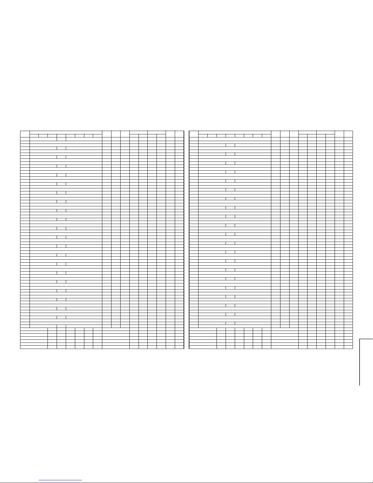
140 S-SYS AFT (auto) C-SYS 10
141 TUNING FREQUANCY (HIGHER PART) POS13
142 TUNING FREQUANCY (LOWER PART)
143 S-SYS AFT (auto) C-SYS 10
144 TUNING FREQUANCY (HIGHER PART) POS 14
145 TUNING FREQUANCY (LOWER PART)
146 S-SYS AFT (auto) C-SYS 10
147 TUNING FREQUANCY (HIGHER PART) POS 15
148 TUNING FREQUANCY (LOWER PART)
149 S-SYS AFT (auto) C-SYS 10
14A TUNING FREQUANCY (HIGHER PART) POS 16
14B TUNING FREQUANCY (LOWER PART)
14C S-SYS AFT (auto) C-SYS 10
14D TUNING FREQUANCY (HIGHER PART) POS 17
14E TUNING FREQUANCY (LOWER PART)
14F S-SYS AFT (auto) C-SYS 10
150 TUNING FREQUANCY (HIGHER PART) POS 18
151 TUNING FREQUANCY (LOWER PART)
152 S-SYS AFT (auto) C-SYS 10
153 TUNING FREQUANCY (HIGHER PART) POS 19
154 TUNING FREQUANCY (LOWER PART)
155 S-SYS AFT (auto) C-SYS 10
156 TUNING FREQUANCY (HIGHER PART) POS 20
157 TUNING FREQUANCY (LOWER PART)
158 S-SYS AFT (auto) C-SYS 10
159 TUNING FREQUANCY (HIGHER PART) POS 21
15A TUNING FREQUANCY (LOWER PART)
15B S-SYS AFT (auto) C-SYS 10
15C TUNING FREQUANCY (HIGHER PART) POS 22
15D TUNING FREQUANCY (LOWER PART)
15E S-SYS AFT (auto) C-SYS 10
15F TUNING FREQUANCY (HIGHER PART) POS 23
160 TUNING FREQUANCY (LOWER PART)
161 S-SYS AFT (auto) C-SYS 10
162 TUNING FREQUANCY (HIGHER PART) POS 24
163 TUNING FREQUANCY (LOWER PART)
164 S-SYS AFT (auto) C-SYS 10
165 TUNING FREQUANCY (HIGHER PART) POS 25
166 TUNING FREQUANCY (LOWER PART)
167 S-SYS AFT (auto) C-SYS 10
168 TUNING FREQUANCY (HIGHER PART) POS 26
169 TUNING FREQUANCY (LOWER PART)
16A S-SYS AFT (auto) C-SYS 10
16B TUNING FREQUANCY (HIGHER PART) POS 27
16C TUNING FREQUANCY (LOWER PART)
16D S-SYS AFT (auto) C-SYS 10
16E TUNING FREQUANCY (HIGHER PART) POS 28
16F TUNING FREQUANCY (LOWER PART)
170 S-SYS AFT (auto) C-SYS 10
171 TUNING FREQUANCY (HIGHER PART) POS 29
172 TUNING FREQUANCY (LOWER PART)
173 S-SYS AFT (auto) C-SYS 10
174 TUNING FREQUANCY (HIGHER PART) POS 30
175 TUNING FREQUANCY (LOWER PART)
176 S-SYS AFT (auto) C-SYS 10
177 TUNING FREQUANCY (HIGHER PART) POS 31
178 TUNING FREQUANCY (LOWER PART)
179 S-SYS AFT (auto) C-SYS 10
17A TUNING FREQUANCY (HIGHER PART) POS 32
17B TUNING FREQUANCY (LOWER PART)
17C S-SYS AFT (auto) C-SYS 10
17D TUNING FREQUANCY (HIGHER PART) POS 33
17E TUNING FREQUANCY (LOWER PART)
17F S-SYS AFT (auto) C-SYS 10
MODEL MODEL
LETTER NO. LETTER NO.
ADDRESS
DATA
MICON EEPROM EEPROM CHASSIS CTV FINAL
LAST INTIAL
(HEX)
D7 D6 D5 D4 D3 D2 D1 D0
DEFAULT RANGE
WRITE (CPU)
CHECK DATA CHECK TYPE CHECK DATA CHECK TYPE
SETTING DATA
REMARK
180 TUNING FREQUANCY (HIGHER PART) POS 34
181 TUNING FREQUANCY (LOWER PART)
182 S-SYS AFT (auto) C-SYS 10
183 TUNING FREQUANCY (HIGHER PART) POS 35
184 TUNING FREQUANCY (LOWER PART)
185 S-SYS AFT (auto) C-SYS 10
186 TUNING FREQUANCY (HIGHER PART) POS 36
187 TUNING FREQUANCY (LOWER PART)
188 S-SYS AFT (auto) C-SYS 10
189 TUNING FREQUANCY (HIGHER PART) POS 37
18A TUNING FREQUANCY (LOWER PART)
18B S-SYS AFT (auto) C-SYS 10
18C TUNING FREQUANCY (HIGHER PART) POS 38
18D TUNING FREQUANCY (LOWER PART)
18E S-SYS AFT (auto) C-SYS 10
18F TUNING FREQUANCY (HIGHER PART) POS 39
190 TUNING FREQUANCY (LOWER PART)
191 S-SYS AFT (auto) C-SYS 10
192 TUNING FREQUANCY (HIGHER PART) POS 40
193 TUNING FREQUANCY (LOWER PART)
194 S-SYS AFT (auto) C-SYS 10
195 TUNING FREQUANCY (HIGHER PART) POS 41
196 TUNING FREQUANCY (LOWER PART)
197 S-SYS AFT (auto) C-SYS 10
198 TUNING FREQUANCY (HIGHER PART) POS 42
199 TUNING FREQUANCY (LOWER PART)
19A S-SYS AFT (auto) C-SYS 10
19B TUNING FREQUANCY (HIGHER PART) POS 43
19C TUNING FREQUANCY (LOWER PART)
19D S-SYS AFT (auto) C-SYS 10
19E TUNING FREQUANCY (HIGHER PART) POS 44
19F TUNING FREQUANCY (LOWER PART)
1A0 S-SYS AFT (auto) C-SYS 10
1A1 TUNING FREQUANCY (HIGHER PART) POS 45
1A2 TUNING FREQUANCY (LOWER PART)
1A3 S-SYS AFT (auto) C-SYS 10
1A4 TUNING FREQUANCY (HIGHER PART) POS 46
1A5 TUNING FREQUANCY (LOWER PART)
1A6 S-SYS AFT (auto) C-SYS 10
1A7 TUNING FREQUANCY (HIGHER PART) POS 47
1A8 TUNING FREQUANCY (LOWER PART)
1A9 S-SYS AFT (auto) C-SYS 10
1AA TUNING FREQUANCY (HIGHER PART) POS 48
1AB TUNING FREQUANCY (LOWER PART)
1AC S-SYS AFT (auto) C-SYS 10
1AD TUNING FREQUANCY (HIGHER PART) POS 49
1AE TUNING FREQUANCY (LOWER PART)
1AF S-SYS AFT (auto) C-SYS 10
1B0 TUNING FREQUANCY (HIGHER PART) POS 50
1B1 TUNING FREQUANCY (LOWER PART)
1B2 S-SYS AFT (auto) C-SYS 10
1B3 TUNING FREQUANCY (HIGHER PART) POS 51
1B4 TUNING FREQUANCY (LOWER PART)
1B5 S-SYS AFT (auto) C-SYS 10
1B6 TUNING FREQUANCY (HIGHER PART) POS 52
1B7 TUNING FREQUANCY (LOWER PART)
1B8 S-SYS AFT (auto) C-SYS 10
1B9 TUNING FREQUANCY (HIGHER PART) POS 53
1BA TUNING FREQUANCY (LOWER PART)
1BB S-SYS AFT (auto) C-SYS 10
1BC TUNING FREQUANCY (HIGHER PART) POS 54
1BD TUNING FREQUANCY (LOWER PART)
1BE S-SYS AFT (auto) C-SYS 10
1BF TUNING FREQUANCY (HIGHER PART) POS 55
MODEL MODEL
LETTER NO. LETTER NO.
ADDRESS
DATA
MICON EEPROM EEPROM CHASSIS CTV FINAL
LAST INTIAL
(HEX)
D7 D6 D5 D4 D3 D2 D1 D0
DEFAULT RANGE
WRITE (CPU)
CHECK DATA CHECK TYPE CHECK DATA CHECK TYPE
SETTING DATA
REMARK
 Loading...