


20MR10M
1
COLOR TELEVISION
Chassis No. CD-A
In the interests of user-safety (Required by safety regulations in some countries) the set should be restored to its
original condition and only parts identical to those specified should be used.
» ELECTRICAL SPECIFICATIONS......................................................................................................... 1
» IMPORT ANT SERVICE SAFETY PRECAUTION................................................................................. 2
»LOCATION OF USER'S CONTROL.....................................................................................................4
»INSTALLATION AND SERVICE INSTRUCTIONS................................................................................5
»CHASSIS LAYOUT............................................................................................................................10
»BLOCK DIAGRAM.............................................................................................................................11
»SCHEMATIC DIAGRAMS..................................................................................................................12
»PRINTED WIRING BOARD ASSEMBLIES........................................................................................15
»REPLACEMENT PARTS LIST...........................................................................................................18
»PACKING OF THE SET.....................................................................................................................23
Page
SHARP CORPORATION
This document has been published to be used for after
sales service only.
The contents are subject to change without notice.
CONTENTS
SERVICE MANUAL
POWER INPUT................................120 V AC 60 Hz
POWER RATING .............................................69 W
PICTURE SIZE.......................1,194cm
2 (185sq inch)
CONVERGENCE........................................Magnetic
SWEEP DEFLECTION................................Magnetic
FOCUS...........................Hi-Bi-Potential Electrostatic
INTERMEDIATE FREQUENCIES
Picture IF Carrier Frequency ................. 45.75 MHz
Sound IF Carrier Frequency .................. 41.25 MHz
Color Sub-Carrier Frequency ................ 42.17 MHz
(Nominal)
ELECTRICAL SPECIFICATIONS
AUDIO POWER
OUTPUT RATING...........1.0 W (at 10% distortion)
SPEAKER
SIZE .................................................. 8 cm (Round)
VOICE COIL IMPEDANCE...........8 ohm at 400 Hz
ANTENNA INPUT IMPEDANCE
VHF/UHF................................ 75 ohm Unbalanced
TUNING RANGES
VHF-Channels.......................................... 2 thru 13
UHF-Channels........................................ 14 thru 69
CATV Channels...................................... 1 thru 125
(EIA, Channel Plan U.S.A.)
Specifications are subject to change without
prior notice.
MODELS
20MR10M
20MR10M
2
IMPORT ANT SER VICE SAFETY PRECAUTION
Ë
Service work should be performed only by qualified service technicians who are thoroughly
familiar with all safety checks and the servicing guidelines which follow:
4A 125V
SERVICING OF HIGH VOL T AGE SYSTEM
AND PICTURE TUBE
When servicing the high voltage system,
remove the static charge by connecting a
10k ohm resistor in series with an insulated
wire (such as a test probe) between the pic-
ture tube ground and the anode lead. (AC
line cord should be disconnected from AC
outlet.)
1. Picture tube in this receiver employs integral
implosion protection.
2. Replace with tube of the same type number for
continued safety .
3. Do not lift picture tube by the neck.
4. Handle the picture tube only when wearing
shatterproof goggles and after discharging the high
voltage anode completely .
X-RADIA TION AND HIGH VOL TAGE LIMITS
1. Be sure all service personnel are aware of the
procedures and instructions covering X-radiation.
The only potential source of X-ray in current solid
state TV receivers is the picture tube. However, the
picture tube does not emit measurable X-Ray
radiation, if the high voltage is as specified in the
"High Voltage Check" instructions.
It is only when high voltage is excessive that X-
radiation is capable of penetrating the shell of the
picture tube including the lead in the glass material.
The important precaution is to keep the high voltage
below the maximum level specified.
2. It is essential that servicemen have available at all
times an accurate high voltage meter.
The calibration of this meter should be checked
periodically.
3. High voltage should always be kept at the rated value
-no higher. Operation at higher voltages may cause
a failure of the picture tube or high voltage circuitry
and;also, under certain conditions, may produce
radiation in exceeding of desirable levels.
4. When the high voltage regulator is operating properly
there is no possibility of an X-radiation problem.
Every time a color chassis is serviced, the brightness
should be tested while monitoring the high voltage
with a meter to be certain that the high voltage does
not exceed the specified value and that it is regulating
correctly .
5. Do not use a picture tube other than that specified
or make unrecommended circuit modifications to the
high voltage circuitry .
6. When troubleshooting and taking test measurements
on a receiver with excessive high voltage, avoid being
unnecessarily close to the receiver.
Do not operate the receiver longer than is necessary
to locate the cause of excessive voltage.
WARNING
1. For continued safety, no modification of any circuit
should be attempted.
2. Disconnect AC power before servicing.
3. Semiconductor heat sinks are potential shock
hazards when the chassis is operating.
4. The chassis in this receiver has two ground systems
which are separated by insulating material. The non-
isolated (hot) ground system is for the B+ voltage
regulator circuit and the horizontal output circuit. The
isolated ground system is for the low B+ DC voltages
and the secondary circuit of the high voltage
transformer.
To prevent electrical shock use an isolation
transformer between the line cord and power
receptacle, when servicing this chassis.
CAUTION: FOR CONTINUED
PROTECTION AGAINST A
RISK OF FIRE, REPLACE
ONLY WITH SAME TYPE 4A-
125V FUSE.
20MR10M
3
234567890123456789012345678901212345678901234567890123456789012123456789012345678901234567890121
2
234567890123456789012345678901212345678901234567890123456789012123456789012345678901234567890121
2
SAFETY NOTICE
Many electrical and mechanical parts in television
receivers have special safety-related characteristics.
These characteristics are often not evident from visual
inspection, nor can protection afforded by them be
necessarily increased by using replacement components
rated for higher voltage, wattage and etc.
Replacement parts which have these special safety
characteristics are identified in this manual; electrical
components having such features are identified by "å"
and shaded areas in the Replacement Parts Lists and
Schematic Diagrams.
IMPORTANT SERVICE SAFETY PRECAUTION
(Continued)
1. Inspect all lead dress to make certain that leads are
not pinched or that hardware is not lodged between
the chassis and other metal parts in the receiver.
2. Inspect all protective devices such as non-metallic
control knobs, insulating materials, cabinet backs,
adjustment and compartment covers or shields,
isolation resistor-capacity networks, mechanical
insulators and etc.
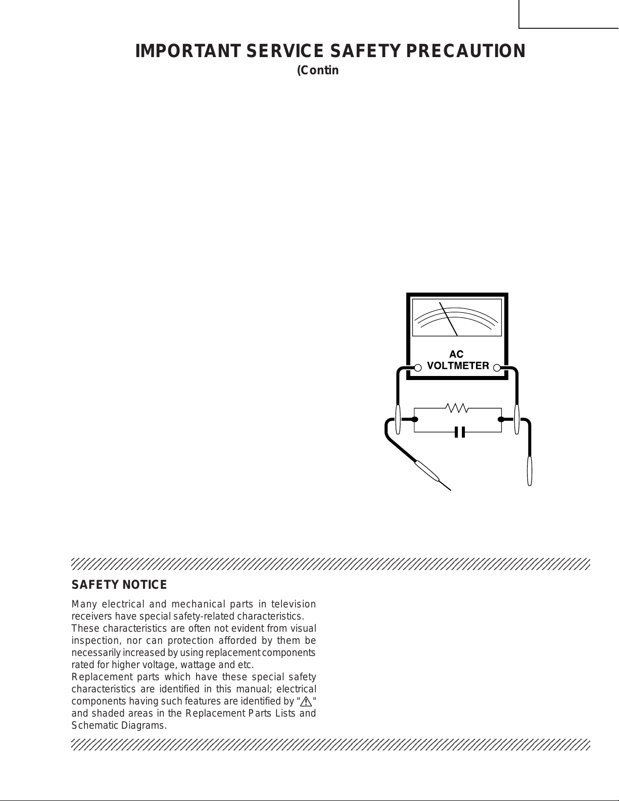
3. To be sure that no shock hazard exists, check for
leakage current in the following manner.
» Plug the AC cord directly into a 120 volt AC outlet,
(Do not use an isolation transformer for this test).
» Using two clip leads, connect a 1.5k ohm, 10 watt
resistor paralleled by a 0.15mF capacitor in series
with all exposed metal cabinet parts and a known
earth ground, such as electrical conduit or electrical
ground connected to earth ground.
» Use an AC voltmeter having with 5000 ohm per volt,
or higher, sensitivity to measure the AC voltage drop
across the resistor.
For continued protection, replacement parts must be
identical to those used in the original circuit. The use of
substitute replacement parts which do not have the same
safety characteristics as the factory recommended
replacement parts shown in this service manual, may
create shock, fire, X-radiation or other hazards.
BEFORE RETURNING THE RECEIVER
(Fire & Shock Hazard)
Before returning the receiver to the user, perform
the following safety checks.
» Connect the resistor connection to all exposed metal
parts having a return to the chassis (antenna, metal
cabinet, screw heads, knobs and control shafts,
escutcheon and etc.) and measure the AC voltage
drop across the resistor.
AII checks must be repeated with the AC ine cord
plug connection reversed. (If necessary, a non-
polarized adapter plug must be used only for the
purpose of completing these check.)
Any current measured must not exceed 0.5 milliamp.
Any measurements not within the limits outlined
above indicate of a potential shock hazard and
corrective action must be taken before returning the
instrument to the customer.
1.5k ohm
10W
0.15µF
TEST PROBE
CONNECT TO
KNOWN EARTH
GROUND
TO EXPOSED
METAL PARTS
20MR10M
4
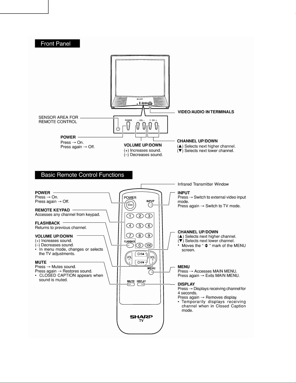
LOCATION OF USER'S CONTROL
20MR10M

5
CIRCUIT PROTECTION
The receiver is protected by a 4.0A fuse (F701),
mounted on PWB-A, wired into one side of the AC
line input.
X-RADIA TION PROTECTOR CIRCUIT TEST
After service has been performed on the horizontal
deflection system, high voltage system, +B system,
test the X-Radiation protection circuit to ascertain
proper operation as follows:
1) Apply 120V AC using a variac transformer for
accurate input voltage.
2) Allow for warm up and adjust all customer controls
for normal picture and sound.
3) Receive a good local channel.
4) Connect a digital voltmeter to TP653 and make sure
that the voltmeter reads 21.3 ±1.5 V.
5) Apply external 28.9V DC at TP653 by using an
external DC supply, TV must be shut off.
6) T o reset the protector, unplug the AC cord and make
a short circuit between TP651 and TP652. Now make
sure that normal picture appears on the screen.
7) If the operation of the horizontal oscillator does not
stop in step 5, the circuit must be repaired before
the set is returned to the customer.
HIGH VOL T AGE CHECK
High voltage is not adjustable but must be checked
to verify that the receiver is operating within safe
and efficient design limitations as specified checks
should be as follows:
1. Connect an accurate high voltage meter between
ground and anode of picture tube.
2. Operate receiver for at least 15 minutes at 120V AC
line voltage, with a strong air signal or a properly
tuned in test signal.
3. Enter the service mode and select the service
adjustment "S19" and Bus data "01" (Y-mute on).
4. The voltage should be approximately, 26.0kV (at zero
beam).
If a correct reading cannot be obtained, check
circuitry for malfunctioning components. After the
voltage test, make Y-mute off to the normal mode.
INSTALLATION AND SERVICE INSTRUCTIONS
Note: (1)When performing any adjustments to resistor controls and transformers use non-metallic
screwdrivers or TV alignment tools.
(2)Before performing adjustments, the TV set must be on at least 15 minutes.
20MR10M
6
Figure A.
S01
02
CHANNEL
SERVICE ADJUSTMENT NUMBER
DATA NUMBER
S01 D:00
For adjustments of this model, the bus data is converted to various analog signals by the D/A converter
circuit.
Note: There are still a few analog adjustments in this series such as focus and master screen voltage.
Follow the steps below whenever the service adjustment is required. See "Table-B" to determine, if serv-
ice adjustments are required.
1. Service mode
Before putting unit into the service mode, check that
customer adjustments are in the normal mode. Use
the reset function in the video adjustment menu to
ensure customer controls are in their proper (reset)
position.
2. Service number selection
Once in the service mode, press the Ch-up or Ch-
down button on the remote controller or at the set.
The service adjustment number will vary in
increments of one, from "S01" to "OP". Select the
item you wish to adjust.
3. Data number selection
Press the Vol-up or down button to adjust the data
number.
To enter the service mode and exit service
mode.
While pressing the Vol-up and Ch-up buttons at the
sametime, plug the AC cord into a wall socket.
Now the TV set is switched on and enters the service
mode.
To exit the service mode, turn the television off by
pressing the power button.
55(085)
20MR10M
7
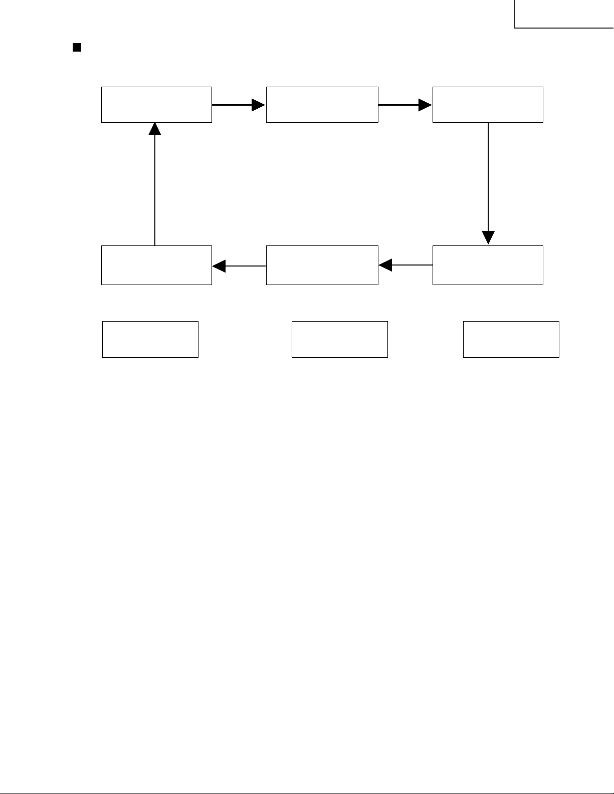
SERVICE MODE
(1) In the Service Mode, Key is used to select the mode in the following oreder.
AGC & WHITE POINT SUB
GEOMETRIC ADJ. ADJ.
MODE MODE MODE
OFFSET
ADJ.
MODE
FEATURE IC
OPTION OPTION
MODE MODE
AGC &
GEOMETRIC
MODE
↓
AGC TAKE OVER POINT (AGC)
↓
VERTICAL SLOPE (V-LIN)
↓
VERTICAL AMP (V-AMP)
↓
VERTICAL SHIFT (V-CENT)
↓
VERTICAL ZOOM (V-ZOOM)
↓
HORIZONTAL SHIFT (H-CENT)
↓
EAST-WEST WIDTH (H-SIZE)
↓
HORIZONTAL PARALLELOGRAM (EW//)
↓
EAST-WEST PARABOLA / WIDTH (PARA)
↓
EAST-WEST UPPER CORNER
PARABOLA (COR(U))
↓
EAST-WEST LOWER CORNER
PARABOLA (COR(L))
↓
EAST-WEST TRAPEZIUM (TRAPE)
↓
HORIZONTAL BOW (HB)
↓
S-CORRECTION (S-COR)
WHITE POINT
ADJ.
MODE
↓
W.P. RED OFFSET HIGH /
OFFSET BLUE TONE (DRI-R-HI)
↓
W.P. GREEN OFFSET HIGH /
OFFSET BLUE TONE (DRI-G-HI)
↓
W.P.BLUE OFFSET HIGH /
OFFSET BLUE TONE (DRI-B-HI)
↓
W.P. RED MH / STD (DRI-R-MH)
↓
W.P. GREEN MH / STD (DRI-G-MH)
↓
W.P. BLUE MH / STD (DRI-B-MH)
↓
W.P. RED OFFSET ML /
OFFSET RED TONE (DRI-R-ML)
↓
W.P. GREEN OFFSET ML /
OFFSET RED TONE (DRI-G-ML)
↓
W.P. BLUE OFFSET ML /
OFFSET RED TONE (DRI-B-ML)
↓
W.P. RED OFFSET LOW (DRI-R-LO)
↓
W.P. GREEN OFFSET LOW (DRI-G-LO)
↓
W.P. BLUE OFFSET LOW (DRI-B-LO)
SUB
ADJ.
MODE
↓
MAX VOLUME (SUB-VOL)
↓
SUB CONTRAST (SUB-CON)
↓
SUB TINT (SUB-TINT)
↓
SUB COLOUR (SUB-COL)
↓
SUB BRIGHTNESS (SUB-BRI)
↓
SUB SHARPNESS (SUB-SHP)
↓
MAX HOTEL VOLUME (HTL-VOL)
↓
HOTEL PROGRAM NO(HTL-PRG)
↓
BLUE BACK CONTRAST (BB-CON)
↓
OSD GRB REFERENCE (RGB)
↓
BLACK LEVEL OFFSET R(CUT-R)
↓
BLACK LEVEL OFFSET G(CUT-G)
↓
CATHODE DRIVE LEVEL(CDL)
20MR10M
 Loading...