


21HM-10F
SERVICE MANUAL
SEJB21HM10F00
Issued: 31st October 2001
GA-1E CHASSIS
SECAM B/G, L/L’ - PAL B/G SYSTEM COLOUR TELEVISION
MODEL 21HM-10F
In the interests of user safety (required by safety regulations in some countries) the set should restored to its original condition and only parts identical to those specified should be used.
CONTENTS
ELECTRICAL SPECIFICATION......................... |
3 |
PRINTED WIRING BOARDS........................... |
14 |
IMPORTANT SERVICING NOTES ................... |
4 |
ICs ADITIONAL INFORMATION...................... |
19 |
CONTROLS & TERMINALS.............................. |
5 |
SCHEMATIC DIAGRAM, WAVE FORMS........ |
25 |
SERVICE ADJUSTMENTS................................ |
6 |
BLOCK DIAGRAM........................................... |
32 |
CHASSIS LAYOUT........................................... |
12 |
TROUBLESHOOTING TABLES...................... |
35 |
LED FLASHING CODE.................................... |
13 |
PARTS LISTING............................................. |
38 |
SHARP CORPORATION
1 |
This document has been published to |
be used for after sales service only. |

21HM-10F
ELECTRICAL SPECIFICATIONS
•Power Input ....................... |
220V-240 Volts AC 50Hz |
•Sound Carrier Trap |
|||
|
|
|
L’.......................................................... |
|
40.4MHz |
•Power Consumption |
|
|
L........................................................... |
|
32.4MHz |
|
|
B/G |
|
33.4MHz |
|
Normal Operation |
|
43W |
|
||
|
•Adjacent |
Sound Carrier Trap |
|||
Stand-by Operation |
|
3W |
|||
|
L’ |
|
32.4MHz |
||
|
|
|
|
||
|
|
|
L, B/G................................................... |
40.4MHz |
|
•Audio Power Output Rating ..................... |
4W (MPO) |
•Adjacent |
Picture |
Carrier Trap |
|
Speaker................................ |
16Ω 4W, 9 x 5 cm, 1pc |
L’.......................................................... |
|
41.9MHz |
|
|
|
|
L........................................................... |
|
30.9MHz |
Convergence |
Self Converging System |
B/G....................................................... |
|
30.9MHz |
|
|
|
|
|||
Focus.................................... |
Bi-Potencial Electrostatic |
•Aerial Input Impedance |
|||
Sweep Deflection |
|
Magnetic |
|||
|
VHF/UHF |
75 ohm Unbalanced |
|||
|
|
|
|||
• |
|
38.9MHz |
•Tuning Ranges |
|
|
Picture Intermediate Frecuency.............. |
L/L’ |
|
55.75MHz thru 855.25 MHz |
||
|
|
|
|
||
|
|
|
B/G......................... |
|
48.25MHz thru 855.25 MHz |
|
|
|
|
CATV Special Channels |
|
•White Level
Set the brightness control, with no signal connected, so that the CRT cathode current is 600mA. The maximum correction applied to each cathode current to achieve a screen temperature of 8900 degrees K-20 MPCD should
not exceed 15% of its original value.
X |
Y |
Screen temperature |
0.290 ± 0.015 |
0.284 ± 0.015 |
8900º K-20 MPCD |
|
|
|
Specifications are subject to change without prior notice.
WARNING
The chassis in this receiver is partially hot. Use an isolation transformer between the line cord plug and power receptacle, when servicing this chassis.
To prevent electric shock, do not remove cover. No user-serviceable parts inside. Refer servicing to qualified service personnel.
3

21HM-10F
IMPORTANT SERVICING NOTES
Only qualified service personnel are allowed to carry out maintenance and repair of this receiver.
SERVICING OF HIGH VOLTAGE SYSTEM AND CRT
It is important that the static charge is removed from the high voltage system when carrying out work on the receiver. This can be achieved by connecting a 10K resistor (with a suitably insulated lead) from the CRT cavity connector to the CRT ground tag. This must be carried out with the AC supply disconnected from the receiver.
Note the following:
•The CRT in this receiver employs Integral Implosion Protection.
•If the CRT has to be changed it MUST be replaced with the correct type for continued safe working
•DO NOT lift the CRT by its neck.
•When handing the CRT, ensure that shatterproof goggles are worn.
•Ensure that the CRT is discharge before handling.
X-RAY
This receiver is designed to keep any x-ray emission to an absolute minimum. Some fault conditions and servicing procedures may produce potentially hazardous x-ray radiation levels. This is a problem when in close proximity to the receiver for long periods of time. To reduce any risks associated with this, please observe the following precautions:
1.When undertaking any servicing on this chassis, DO NOT increase the EHT to more than 30.5 KV, (at a instantaneous beam current of 1300µΑ).
2.Ensure that during normal operation the EHT does not exceed 25.0 KV±1.5KV (at a beam current of 1100µΑ). This level has been preset in the factory. Always check that this level has not been ex-
ceeded after carrying out any repair on the receiver.
3. DO NOT replace the CRT with any other type than that specified in the parts listing as this may cause excessive x-ray radiation.
BEFORE RETURNING THE RECEIVER TO THE CUSTOMER
In addition to the above checks, the following should also be carried out before returning the receiver to the customer.
1.Inspect all the leads to ensure that they are dressed correctly and that they are not obstructed or pinched by any other parts.
2.Ensure that all protective devices are in good condition. These will include nonmetallic control knobs, insulating fish papers, cabinets backs, compartment covers or shields, mechanical insulators,
etc.
4

21HM-10F
 Location of Controls
Remote Control
POWER/STANDBY (  ) button
Programme Select buttons
FLASHBACK (  ) buttons Returns to previously viewed programme
VOLUME UP ( )/DOWN ( ) buttons ( ) Increases sound
() Decreases sound
(These are also used for menu set up)
TV/VIDEO
1 2 3
4 5 6
7 8 9
0
CH
CH
MENU
Infrared Transmitter Window
Aim this window at the infrared sensor on your TV set
TV/VIDEO Select button
Single/Double Entry button ( )
)
CHANNEL (PROGRAMME) UP ( )/ DOWN ( ) buttons
( ) Selects next higher programme ( ) Selects next lower programme (These are also used for menu
set up)
|
MENU button |
SOUND MUTE ( ) button |
CHILD LOCK ( ) button |
CALL button ( )
)
TV
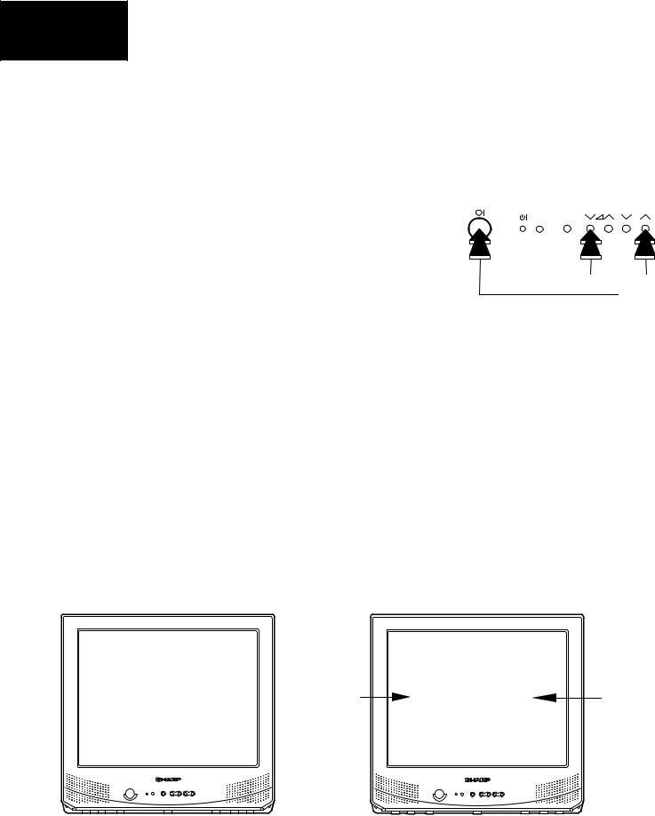
TV Front
MENU |
CH |
|
|
|
|
|
|
|
|
|
|
|
|
|
|
|
|
|
|
|
|
|
|
|
|
|
|
|
|
|
|
|
|
|
|
|
|
|
|
|
|
|
|
|
|
|
|
|
|
|
|
|
|
|
|
Power ( ) button |
|
|
|
|
|
|
|
|
|
|
|
|
|
|
Channel Up ( |
)/Down ( ) buttons |
|
Power/On Timer indicator |
|
|
|
|
|
|
|
|
|
|
|
|
|||||
|
|
|
|
|
|
|
|
|
|
|
|
||||||
|
|
|
|
|
|
|
|
|
|
|
|||||||
Remote Control Sensor |
|
|
|
|
|
|
|
Volume Up ( )/Down ( |
) buttons |
||||||||
|
|
|
|
|
|
|
|||||||||||
|
|
|
|
|
|
Menu button |
|
|
|||||||||
Euro-SCART 21-Pin Terminal
21-Pin Euro-
For greater A/V enjoyment, various audio and video devices may be connected via the Euro-SCART 21-Pin Terminal.
1. |
Audio right output |
8. |
Audio-video control |
15. |
Red input |
18. |
Earth for video |
2. |
Audio right input |
9. |
Earth for green |
16. |
Red/Green/Blue |
19. |
VIDEO output |
3. |
Audio left output |
10. |
Not used |
|
control |
20. |
VIDEO input |
4. |
Common earth for audio |
11. |
Green input |
17. |
Earth for video |
21. |
Common earth |
5. |
Earth for blue |
12. |
Not used |
|
|
|
|
6. |
Audio left input |
13. |
Earth for red |
|
|
|
|
7. |
Blue input |
14. |
Not used |
Audio: Mono Input/Output. |
|
|
|
5
21HM-10F
SERVICE ADJUSTMENT
• SERVICE MODE FUNCTION
All required adjustments for servicing this TV set, may be done in “service mode”, excepting G2 and FOCUS.
HOW TO ACCESS THE SERVICE MODE
1.Turn the receiver on and ensure that it is tuned into a test pattern.
2.Turn the receiver off using the mains switch.
MENU |
CH |
3. |
Press the volume down and channel up buttons together. See Fig.1. |
3 |
||
4. |
Continue pressing the volume down and channel up buttons while turning |
4 |
|
|
|
|
|
||
|
the mains on using the mains switch. See Fig.1. |
|
Fig.1 |
|
5.Keep pressing the volume down and channel up buttons until the picture appears.
6.When <<SHARPX X VXX.XX>> appears on the screen, release the two buttons.
7.The receiver is now in the service mode. See Fig. 2.
To move between the various service mode functions, use the channel up and down buttons. See Fig. 3.
Use the volume buttons to change the data to the desired value. See Fig. 3.
The data will be stored automatically when exiting the service mode. To exit the service mode press the standby button on the remote control or turn the receiver off with the mains switch.
Fig. 2
SHARP X X VXX.XX
STS0: XXXX XXXX
STS1: XXXX XXXX
STS2: XXXX XXXX
Fig. 3
Adjustment |
XXXX: |
XX: |
Value |
(Yellow) |
|
|
(Green) |
6

21HM-10F
• SERVICE ADJUSTMENTS AND DATA LIST
The table below shows the various service mode positions, range of values and default value. The columns are headed as follows.
Heading: |
Description: |
OSD |
This is what will appear on the screen when at this position |
Function |
This is the description of the mode’s function |
Range |
This is the range of values that can be entered while in this mode |
Initial |
This is the initial value, i.e. just after changing the NVM |
Default |
This is the recommended default value for this mode |
FIX/ADJ |
If this is ADJ, then it may be necessary to adjust this value away from the default |
No. |
OSD |
Function |
Range |
Initial |
Default |
FIX/ADJ |
|
|
|
|
|
|
|
|
|
1 |
AGC |
AGC Take Over Point |
0...63 |
14 |
14 |
ADJ |
|
|
|
|
|
|
|
|
|
2 |
V-LIN |
Vertical Slope [VS] |
0...63 |
32 |
32 |
ADJ |
|
|
|
|
|
|
|
|
|
3 |
V-AMP |
Vertical Amplitude [VA] |
0...63 |
32 |
32 |
ADJ |
|
|
|
|
|
|
|
|
|
4 |
V-CENT |
Vertical Shift [VSH] |
0...63 |
32 |
32 |
ADJ |
|
|
|
|
|
|
|
|
|
5 |
H-CENT |
Horizontal shift [HS] |
0...63 |
32 |
32 |
ADJ |
|
|
|
|
|
|
|
|
|
6 |
H-CENT60 |
offset to H-CENT for60 Hz |
0...31 data(-16..+15) |
16 |
20 |
FIX |
|
7 |
EW / / |
Horizontal Parallelogram [HP] |
0...63 |
32 |
32 |
FIX |
|
|
|
|
|
|
|
|
|
8 |
HB |
Horizontal Bow |
0...63 |
32 |
32 |
FIX |
|
|
|
|
|
|
|
|
|
9 |
S-COR |
S-Correction [SC] |
0...63 |
0 |
22 |
FIX |
|
10 |
DRI-RS |
White point Red Standard white temp. |
0...63 |
32 |
42 |
ADJ |
|
11 |
DRI-GS |
White point Green Standard white temp. |
0...63 |
32 |
42 |
ADJ |
|
12 |
DRI-BS |
White point Blue Standard white temp |
0...63 |
32 |
42 |
ADJ |
|
13 |
DRI-RW |
White point Red Warm white temp. |
0...32 |
16 |
16 |
FIX |
|
|
|
|
|
|
|
|
|
14 |
DRI-GW |
White point Green Warm white temp. |
0...32 |
16 |
9 |
FIX |
|
15 |
DRI-BW |
White point Blue Warm white temp. |
0...32 |
16 |
9 |
FIX |
|
16 |
DRI-RC |
White point Red Cold white temp. |
0...32 |
16 |
9 |
FIX |
|
17 |
DRI-GC |
White point Green Cold white temp. |
0...32 |
16 |
9 |
FIX |
|
18 |
DRI-BC |
White point Blue Cold white temp. |
0...32 |
16 |
16 |
FIX |
|
|
|
|
|
|
|
|
|
19 |
SUB-VOL |
Max Volume |
0...63 |
60 |
60 |
FIX |
|
|
|
|
|
|
|
|
|
20 |
SUB-CON |
Sub Contrast |
0...63 |
63 |
63 |
FIX |
|
|
|
|
|
|
|
|
|
21 |
SUB-COL |
Sub Colour |
0...63 |
32 |
18 |
FIX |
|
22 |
SUB-BRI |
Sub Brightness |
0...63 |
32 |
36 |
FIX |
|
23 |
TINT |
Sub Tint |
0...63 |
32 |
32 |
FIX |
|
|
|
|
|
|
|
|
|
24 |
SUB-SHP |
Sub Sharpness |
0...63 |
32 |
18 |
FIX |
|
|
|
|
|
|
|
|
|
7

21HM-10F
No. |
OSD |
Function |
Range |
Initial |
Default |
FIX/ADJ |
|
|
|
|
|
|
|
|
|
25 |
HTL-VOL |
Max Hotel Volume |
0...63 |
30 |
30 |
FIX |
|
26 |
HTL-PRG |
Hotel Program number |
0...99 or > 99 for none |
255 |
255 |
FIX |
|
27 |
RGB |
OSD RGB Reference |
0...15 |
15 |
0 |
FIX |
|
28 |
SEARCH-SYS |
Sound system for auto turning |
0(L-BG),1(BG),2(I),3(DK) |
1 |
0 |
FIX |
|
29 |
CUT-R |
Black Level off-set R [BLR] |
0...63 |
0 |
0 |
FIX |
|
30 |
CUT-G |
Black Level off-set G [BLB] |
0...63 |
0 |
10 |
FIX |
|
31 |
CDL |
Cathode Drive Level [CL] |
0...15 |
0 |
5 |
FIX |
|
32 |
DL-PT |
Y-Delay time for PAL (TV) [YD] |
0...15 |
12 |
4 |
FIX |
|
33 |
DL-ST |
Y-Delay time for SECAM (TV) [YD] |
0...15 |
15 |
8 |
FIX |
|
34 |
DL-4T |
Y-Delay time for N443 (TV) [YD] |
0...15 |
12 |
8 |
FIX |
|
35 |
COL-OP |
COLOUR OFFSET (PAL) |
0...15 |
8 |
8 |
FIX |
|
36 |
COL-OS |
COLOUR OFFSET (SECAM) |
0...15 |
8 |
8 |
FIX |
|
37 |
COL-O4 |
COLOUR OFFSET (NTSC443) |
0...15 |
4 |
4 |
FIX |
|
38 |
SHP-OP |
SHARPNESS OFFSET(PAL) |
0...15 |
8 |
8 |
FIX |
|
39 |
SHP-OS |
SHARPNESS OFFSET(SECAM) |
0...15 |
4 |
4 |
FIX |
|
40 |
SHP-O4 |
SHARPNESS OFFSET(NTSC443) |
0...15 |
8 |
8 |
FIX |
|
41 |
SC-VOL |
SCART volume |
0..255 |
115 |
115 |
FIX |
|
42 |
PRE-SC |
Prescaler SCART input |
0..127 |
25 |
25 |
FIX |
|
43 |
PRE-FM |
Prescaler FM/AM |
0..127 |
72 |
72 |
FIX |
|
44 |
PRE-NICAM |
Prescaler SCART input |
0..127 |
0 |
0 |
FIX |
|
45 |
AVC-DKY |
AVC Decay |
0...3 data(1.2.4.8.) |
2 |
2 |
FIX |
|
46 |
AC-OFF-TIM |
Time to set the AC-OFF |
0..15 |
0 |
0 |
FIX |
|
|
|
timer is in steps of 10minutes |
|
|
|
|
|
47 |
DISP |
Language or symbols |
0(symboles), |
0 |
2 |
FIX |
|
|
|
|
1(English), |
|
|
|
|
|
|
|
2(French) |
|
|
|
|
48 |
TXT-EUR |
Teletext pan-European language |
0 (teletext pan-european language) |
0 |
0 |
FIX |
|
|
|
|
1 |
(second language;cyrillic) |
|
|
|
|
|
|
2(third language;Greek) |
|
|
|
|
49 |
BKS |
Black Stretch |
0 |
(disable) or 1 (enable) |
1 |
1 |
FIX |
50 |
AVC |
Automatic Volume Control(AVL) |
0 (disable) or 1 (enable) |
0 |
1 |
FIX |
|
51 |
FFI |
Fast Filter IF-PLL |
0 |
(disable) or 1 (enable) |
0 |
0 |
FIX |
52 |
ACL |
Auto Colour Limit |
0 |
(disable) or 1 (enable) |
0 |
1 |
FIX |
53 |
S-L |
Sound system L |
0 (disable) or 1 (enable) |
0 |
1 |
FIX |
|
54 |
S-DK |
Sound system DK |
0 |
(disable) or 1 (enable) |
1 |
0 |
FIX |
55 |
S-I |
Sound system I |
0 |
(disable) or 1 (enable) |
1 |
0 |
FIX |
56 |
S-BG |
Sound system BG |
0 |
(disable) or 1 (enable) |
1 |
1 |
FIX |
57 |
BLUE-BACK |
Video mute at Ident loss |
0 |
(disable) or 1 (enable) |
1 |
1 |
FIX |
58 |
VMC |
Video Mute at program/source Change |
0 (disable) or 1 (enable) |
1 |
1 |
FIX |
|
59 |
HTL |
Hotel mode |
0 |
(disable) or 1 (enable) |
0 |
0 |
FIX |
60 |
BTSC |
Reduced FM demodulator Gain (for BTSC sig) |
0 (disable) or 1 (enable) |
0 |
0 |
FIX |
|
61 |
AV |
Number of external AV sources |
0 for 1 AV or 1 for 2 AV |
1 |
0 |
FIX |
|
62 |
FMWS |
FM Window Selection |
0 |
(disable) or 1 (enable) |
0 |
0 |
FIX |
63 |
SM0 |
Sound Mute bit 0 |
0 (disable) or 1 (enable) |
1 |
1 |
FIX |
|
64 |
SM1 |
Sound Mute bit 1 |
0 (disable) or 1 (enable) |
0 |
0 |
FIX |
|
65 |
AGC0 |
IF AGC speed bit0 |
0 |
(disable) or 1 (enable) |
1 |
0 |
FIX |
66 |
AGC1 |
IF AGC speed bit1 |
0 |
(disable) or 1 (enable) |
0 |
0 |
FIX |
67 |
FOA-FE |
Phi 1 time constant for FE(RF) |
0 (disable) or 1 (enable) |
0 |
0 |
FIX |
|
68 |
FOB-FE |
Phi 2 time constant for FE(RF) |
0 (disable) or 1 (enable) |
0 |
0 |
FIX |
|
69 |
FOA-AV |
Phi 1 time constant for AV |
0 (disable) or 1 (enable) |
1 |
1 |
FIX |
|
70 |
FOB-AV |
Phi 2 time constant for AV |
0 (disable) or 1 (enable) |
1 |
1 |
FIX |
|
71 |
TXT |
Teletext |
0 (disable) or 1 (enable) |
0 |
0 |
FIX |
|
72 |
TXT-WE |
Teletext Western or Eastern characters |
0 |
(westem) or 1 (eastem) |
0 |
0 |
FIX |
73 |
FSL |
Forced V-SYNC slicing level |
0 |
(disable) or 1 (enable) |
0 |
0 |
FIX |
74 |
HP2 |
Sync of OSD |
0 for Ph1 or 1 for Ph2 |
0 |
0 |
FIX |
|
75 |
CP |
Charge pump |
0 |
(fast tuning) or |
0 |
0 |
FIX |
|
|
|
1 |
(moderate speed tuning) |
|
|
|
76 |
NICAM |
NICAM decoding enabled |
0 |
(disable) or 1 (enable) |
0 |
0 |
FIX |
77 |
IGR |
IGR decoding enabled |
0 |
(disable) or 1 (enable) |
0 |
0 |
FIX |
78 |
AUTO |
Start auto tuning at POWER-ON |
0 |
(disable) or 1 (enable) |
0 |
0 |
FIX |
79 |
TXT-TGL |
Function of TXT key |
0 or 1 |
0 |
1 |
FIX |
|
80 |
EVG |
Enable Vertical Guard |
0 |
(disable) or 1 (enable) |
1 |
1 |
FIX |
8
21HM-10F
• SCREEN ADJUSTMENT
1.G2 Adjustment
1.Enter the service mode (see page 6).
2.Use the channel up or channel down buttons to enter the << BLUE-BACK >>
function. |
|
|
3.Set this to << BLUE-BACK: 0 >>, i.e. blue background is turned off.
4.Turn the set off at the mains.
5.Turn the set back on.
6.Set the picture control settings to normal.
7.Select the SCART input by pressing the TV/SCART button on the remote control. Do not connect an input to the SCART socket. A blank raster will appear.
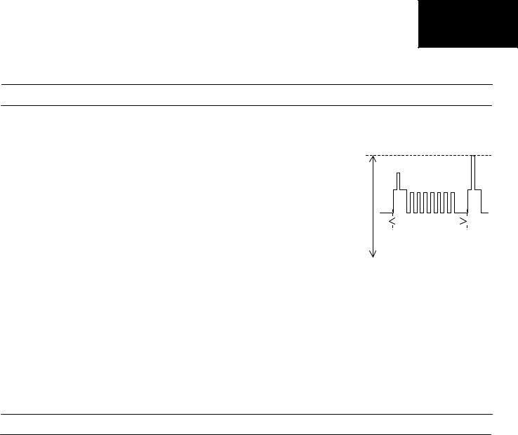
8.Connect an oscilloscope to TP851 on the CRT PWB. The waveform as in figure 4 should be displayed.
9.Adjust the G2 control (screen voltage) so that the peak of this waveform is 3.0V +/-0.1V above the zero volt line.
10.Enter the service mode.
11.Turn the blue background function back on again - set << BLUE-BACK: 1 >>.
12.Turn off the receiver using the mains button.
13.The G2 adjustment is now complete.


Fig. 4
2. Focus Adjustment
1.Receive a monoscope pattern signal at a level of 60 to 80 dB V.
2.Set the picture settings to normal.
3.Adjust the focus potentiometer to obtain maximum definition.
•AGC ADJUSTMENT
1.Tune the receiver into a colour bar signal on channel E-12.
2.Set the RF generator to an output signal strength of 57dB V (+/-1dB V) –50 Ohms unbalanced.
3.Connect an oscilloscope to TP201. TP201 is one end of R201.
4.Enter the service mode (see page 6).
5.Use the channel up and channel down buttons to enter the AGC mode.
6.By using the volume up and the volume down buttons, adjust the AGC until the voltage on TP201 drops by 0.1V to 0.3V below its maximum value.
7.Change the input signal strength to 66-70dB V and make sure that there is no noise apparent in the picture.
8.Turn the receiver off at the mains, this will exit the service mode and store the adjustment.
9
21HM-10F
• GEOMETRY ADJUSTMENT PROCEDURE
To adjust the geometry, follow the procedure outlined below:
1.Tune the set into a Philips test pattern.
2.Enter the service mode as described on page 6.
3.Use the channel up or channel down buttons to enter the desired mode 4.Use the volume buttons to achieve correct setting.
5.When adjustments are complete, use the standby button to turn off the set. The adjustment values will be stored at this point.
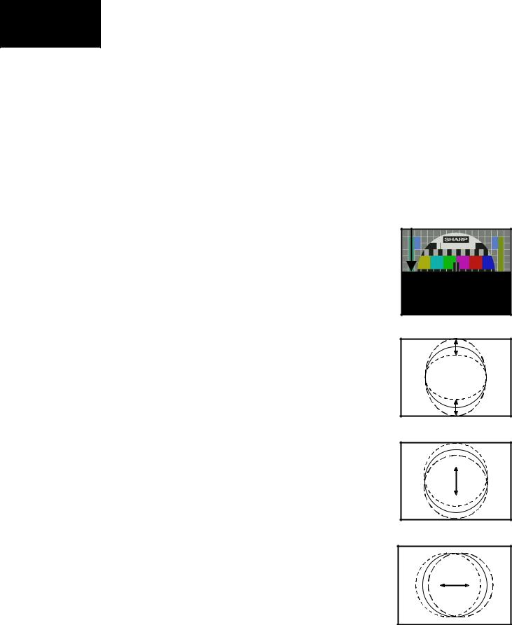
V-LIN
Adjust the vertical linearity control so that the picture centring is as shown in figure 5.
Fig. 5
V-AMP
Adjust the vertical amplitude control so that the picture overscans as shown in figure 6.
Fig. 6
V-CENT
Adjust the vertical centring control so that the picture is centred as shown in figure 7.
Fig. 7
H-CENT
Adjust the horizontal centring control so that the picture is centred as shown in figure 8.
Fig. 8
10

21HM-10F
•COLOUR ADJUSTMENT PROCEDURE
The following adjustments should only be carried out when the CRT or IC801 are replaced.
NOTES:
•This adjustment must be done after warming up the unit for 30 minutes or longer with a beam current over 700 µA.
•The red value «DRI-RS» should be fixed to 42. (Refer to “How to access service mode” section).
•«DRI-GS» adjustment alters “Y” co-ordinate.
•«DRI-BS» adjustment alters “X” and “Y” co-ordinates.
ADJUSTMENT METHOD 1 (using the signal generator, varying the picture signal)
1.Adjust G2.
2.Input a white pattern with burst signal from SCART.
3.Position the colorimeter in the centre of screen.
4.Adjusting input signal level, select a luminance of 70 nits.
5.Operate again in “service mode“ and select «DRI-GS» and/or «DRI-BS» locations to obtain colour co-ordinates:
X |
Y |
Screen temperature |
0.290 ± 0.015 |
0.284 ± 0.015 |
8900º K-20 MPCD |
|
|
|
6.Re-set the TV with the mains switch button to store the adjustment and exit service mode.
7.Check colour co-ordinates “X” and “Y” at 20 a 120 Nits. It may be necessary to repeat the same procedure to obtain the above values.
ADJUSTMENT METHOD 2 (using the signal generator, with a fixed picture signal)
1.Adjust G2.
2.Tune a white pattern with burst signal.
3.Operate in “service mode”:
4.Using «SUB-CON», select a luminance of 70 nits.
5.Operate again in “service mode“ and select «DRI-GS» and/or «DRI-BS» locations to obtain colour co-ordinates:
X |
Y |
Screen temperature |
0.290 ± 0.015 |
0.284 ± 0.015 |
8900º K-20 MPCD |
|
|
|
6.Select «SUB-CON». Return data to “63”.
7.Re-set the TV with the mains switch button to store the adjustment and exit service mode.
8.Check colour co-ordinates “X” and “Y” at 20 a 120 Nits. It may be necessary to repeat the same procedure to obtain the above values.
11
 Loading...