

Page 1
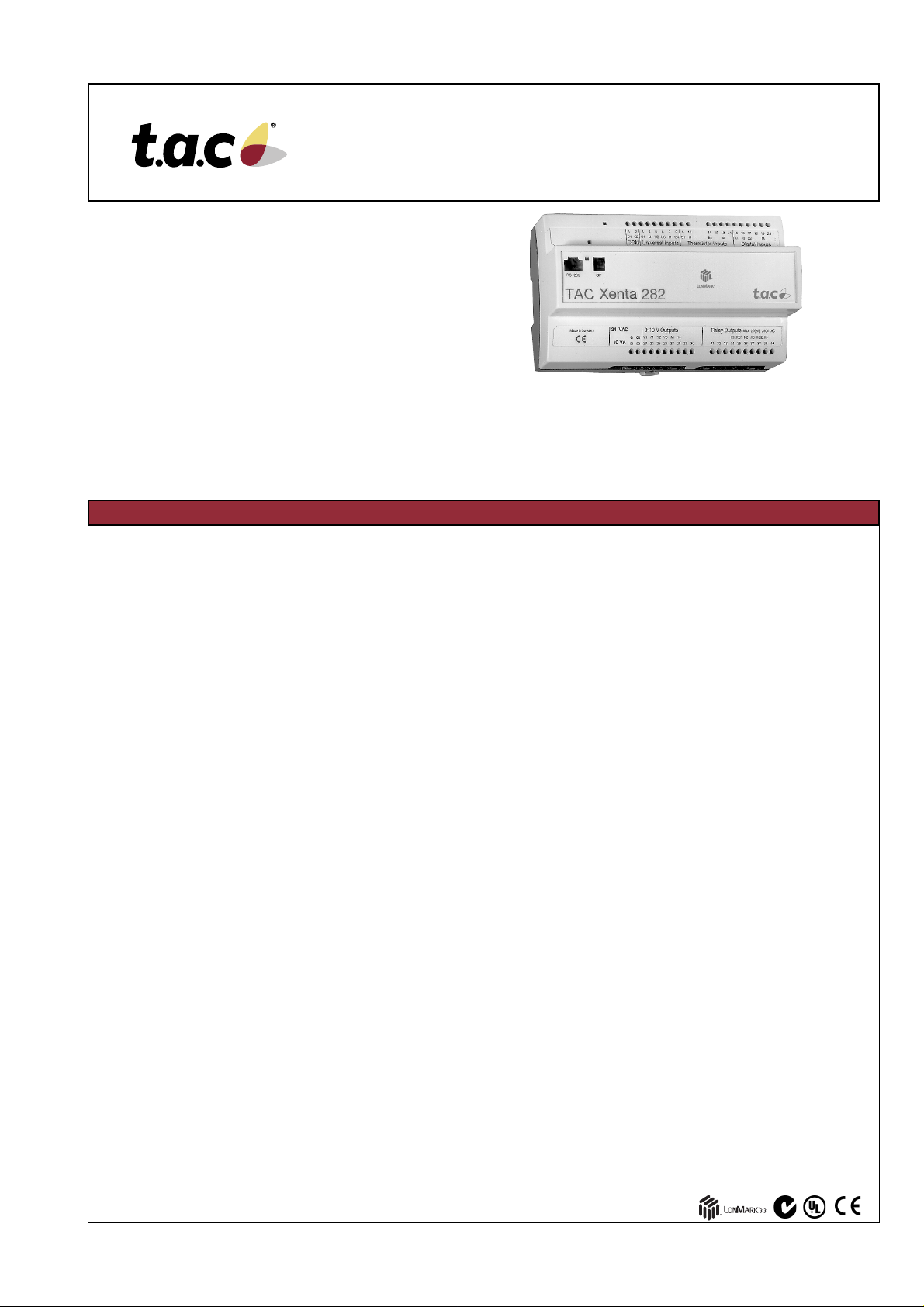
TAC Xenta® 280
Programmable Controller
The TAC Xenta® 280 is a family of programmable
controllers designed for zone control or small-sized
heating and air handling systems.
A TAC Xenta 280 controller contains basic HVAC
functionality including control loops, curves, time control,
alarm handling etc. The TAC Xenta 283 has a LONMARK
Real Time Keeper object.
The Xenta 280 controller is available with three different
I/O configurations, the TAC Xenta 281, 282 and 283.
The controllers are designed for cabinet mounting.
They are simple to program and put into operation,
using the TAC Menta® graphical software tool.
The controller communicates on a LONTALK® TP/FT-10
network via a twisted-pair, unpolarized cable. It is able
to operate as a stand-alone unit and can be easily
connected to a large LONWORKS based network.
TECHNICAL DATA
Supply voltage .... 24 V AC ±20%, 50/60 Hz or 19–40 V DC
Power consumption .............................................. max. 5 W
Transformer sizing ......................................................10 VA
Ambient temperature:
Storage ..............................–20 to +50 °C (–4 to +122 °F)
Operation.............................0 to +50 °C (+32 to +122 °F)
Humidity .............................. max. 90% RH non-condensing
Mechanical:
Enclosure............................................................. ABS/PC
Enclosure rating........................................................IP 20
Dimensions, mm (in.).......180 x 110 x 75 (7.1 x 4.3 x 3.0)
Weight ...................................................... 1.0 kg (2.2 lbs)
Real time clock:
Accuracy at +25 °C (77 °F)............. ±12 minutes per year
Power failure protection............................................. 72 h
Digital inputs (Xenta 281, 282, 283: X1–X2)
Voltage across open contact ............................... 33 V DC
Current through closed contact ................................ 4 mA
Pulse input duration ........................................ min. 20 ms
Universal inputs (Xenta 281, 282: U1–U4)
– as Digital inputs;
Voltage across open contact ............................... 26 V DC
Current through closed contact ................................ 4 mA
Pulse input duration ........................................ min. 20 ms
– as Thermistor inputs;
TAC thermistor sensor............ 1800 ohm at 25 °C (77 °F)
Measuring range...........–50 to +150 °C (–58 to +302 °F)
– as Voltage inputs;
Input signal ......................................................0–10 V DC
Input resistance ................................................ 100 kohm
........................................ accuracy within 1% of full scale
Sensor inputs (B1–B2, only TAC Xenta 282)
TAC thermistor sensor.......... 1800 ohm at 25 °C (+77 °F)
Measuring range...........–50 to +150 °C (–58 to +302 °F)
Sensor inputs (B1–B4, only TAC Xenta 283)
TAC thermistor sensor.......... 1800 ohm at 25 °C (+77 °F)
......or (individually selectable) 10 kohm at 25 °C (+77 °F)
Measuring range.............–20 to +120 °C (–4 to +248 °F)
10 Oct 2003
®
For local use, the TAC Xenta OP operator panel can be
connected. The OP has a display and push buttons for
navigating and altering settings.
The operator panel can be snapped onto the
TAC Xenta controller unit, mounted on the front of
the cabinet, or used as a portable terminal.
Digital outputs (relays; Xenta 281: K1–K3, Xenta 282: K1–K4)
Control voltage, relay outputs................... up to 230 V AC
Ctrl curr., to be protected by max. 10 A fuse, ..... max. 2 A
Outputs V1–V6 (triac; TAC Xenta 283 only):
Control voltage ........................................... max. 30 V AC
Control current ................................................. max. 0.8 A
Total control current............................................ max. 3 A
Analog outputs (Xenta 281: Y1–Y3, Xenta 282: Y1–Y4)
Control voltage ................................................0–10 V DC
Control current, short-circuit proof ................... max. 2 mA
Deviation............................................................ max ±1%
Communication:
TAC Menta ................................. 9600 bps, RS232, RJ45
TAC Vista, also for application program download
..................................................TP/FT-10, screw terminal
TAC Xenta OP.............................TP/FT-10, modular jack
®
ONMARK
L
TAC Xenta 281, 282:
Interoperability ............ L
Application .. L
TAC Xenta 283:
Interoperability ............ LONMARK Interop. Guidelines v 3.3
Application ..... L
Agency Compliances:
Emission .....................C-Tick, EN 50081-1, FCC Part 15
Immunity ........................................................ EN 50082-1
Safety:
Part numbers:
Electronics part TAC Xenta 281/N/P .............. 0-073-0030
Electronics part TAC Xenta 282/N/P .............. 0-073-0031
Electronics part TAC Xenta 283/N/P .............. 0-073-0032
Terminal part TAC Xenta 280/300..................0-073-0901
Operator terminal TAC Xenta OP................... 0-073-0907
TAC Xenta: Programming Serial Kit ...............0-073-0920
standard:
ONMARK Interop. Guidelines v 3.0
ONMARK Functional Profile: Plant Controller
ONMARK Funct. Profile: Real Time Keeper
CE ............................................................. EN 61010-1
UL 916 (Xenta 283 pending).Energy Mngmnt Equipm.
Flammability class, materials ....................... UL 94 V-0
ETL listing ................................ UL 3111-1, first edition
...................................CAN/CSA C22.2 No. 1010.1-92
Subject to modification.
1 (4) 0-003-2248-4 (EN)
Page 2

DESIGN
The TAC Xenta 280 controller has been
designed as a general purpose unitary
(one-to-one) controller. Thus it can be mounted
in close proximity to the controlled equipment,
minimizing the wiring required.
The TAC Xenta 280 is microprocessor
based. It consists of a terminal and electronics fitted together (Figure 1).
The Xenta 280 can be interfaced with a
wide variety of field sensors/transducers
and controlled devices. All terminations of
field wires are done on the terminal part
only. Thus the electronics part may be
removed for service without affecting the
terminal connections.
Local operator terminal
The TAC Xenta OP is a small operator
terminal which can be connected to the
unit through its enclosure. The operator
can read the point status, perform manual
override, read measured values, alter set
points etc., from the TAC Xenta OP.
Functions are selected from menus. Access to the unit is enabled by using an
access code. It is possible to access other
TAC Xenta units on the same network.
Real-time clock
The clock provides data such as the year,
month, date, day, hour, minute and second.
A built-in capacitor guarantees
operation of the clock for at least 72
hours in the event of a power outage.
The TAC Xenta 283 is intended to be
used as a Real Time Keeper. Real time
is exposed as an output network
variable, SNVT_time_stamp, which can
be bound to other LonWorks devices.
Daylight Saving Time: European,
Australian or USA/Canada
Once set, Daylight Saving Time (DST) is
fully automatic. The change-over date and
the number of hours to change are
programmable. This function can also be
disabled.
Digital Inputs
The DIs are used to sense alarm contacts,
status indications, pulse counting, etc.
Each digital input can be used as a pulse
counter (e.g. for flow measurement).
Another application is alarm monitoring.
Each time an alarm is tripped, the corresponding counter can be incremented,
providing data for operating statistics. The
digital input circuits are internally powered.
Universal Inputs
The universal inputs can be individually
configured as analog or digital inputs.
A high and a low limit can be set for each
universal input. If configured as digital
inputs, the universal inputs may be used,
for example, for sensing switch positions.
The universal input types are selected via
the application program.
Figure 1
Thermistor Inputs
The TAC Xenta 282 and 283 have
thermistor inputs, 1800 ohm at 25 °C
(+77 °F).
In the Xenta 283, these inputs are also
individually configurable for 10 kohm at
25 °C (+77 °F).
Digital Outputs
There are digital outputs for controlling
equipment such as fans, pumps or similar
devices. The output signal can be pulsewidth modulated.
In the TAC Xenta 283, the DOs are designed as TRIAC outputs.
Analog Outputs
There are analog outputs for controlling
actuators or connections with controllers.
ONWORKS
L
®
SNVT support
The use of Standard Network Variable
Types, in accordance with the Echelon
specification, makes it possible to communicate with nodes made by other manufacturers.
Power outage protection
Using non-volatile (flash) memory, the
unit will start up with user settings and
work normally after a power outage.
®
I/O CONFIGURATIONS
The Xenta 280 controller is available
with three different I/O configurations,
the TAC Xenta 281, 282 and 283.
The table gives an overview of the
different numbers of inputs and outputs.
No external I/O modules are used with
TAC Xenta DI UI TI DO AO
281 2 4 - 3 3
282 24244
283 2 - 4 6 -
the TAC Xenta 280.
SOFTWARE FEATURES
With the assistance of TAC Menta (4.0
or higher; for Xenta 283 4.10 or higher),
a graphical programming tool using
Functional Block Diagrams (FBDs), the
TAC Xenta 280 may be easily adapted to
different control and monitoring tasks.
The basic software includes preprogrammed routines for:
– reading Digital Inputs (alarms, pulse counting,
interlocks)
– reading Universal Inputs (individually selectable
as analog or digital)
– controlling Digital Outputs
– controlling Analog Outputs
0-003-2248-4 (EN) 2 (4)
– on and off delays
– pulse counting (Digital Inputs only)
– alarm handling; alarm conditions may be de-
tected via the digital or analog inputs.
– equipment run time totals, on selected objects.
– one-time schedule block with four entries (start
and stop times in hours and minutes): weekly
and/or holidays
– programs for optimum start/stop
– outdoor temp. compensating control curves
– PID control loops (loops may be connected in
cascade)
– trend logging (max. 5 kB)
– local level operator interface via TAC Xenta OP
– network communication according to the
L
ONTALK
®
protocol
DI (Xn): Digital input
UI (Un): Universal input
TI (Bn): Thermistor input
DO (Kn,Vn): Digital output
AO (Yn): Analog output
The basic software is adapted to the
current application by connecting preprogrammed Functional Blocks and by
adjusting the relevant parameters.
These connections and parameters are
stored in non-volatile memory.
The parameters may be changed
during operation either from the Central
System or locally from the TAC Xenta
Operator Panel.
Page 3

COMMUNICATION
2
M
l
A
l
F
l
Communication capabilities
The TAC Xenta 280 has several communication capabilities: within the network, with
a central presentation system and with a
hand-held Operator Panel.
ONWORKS connection
L
TAC Xenta controllers communicate with
each other using a common network,
ONWORKS TP/FT-10, 78 kbps. A number
L
of controllers can form a network and
exchange data.
The LONTALK protocol makes it possible to
use Network Variables defined in equipment made by other manufacturers.
The Functional Block applications are
modeled as true LONMARK® Controller
Objects.
The Network Variable interface (including
the Standard Network Variable Types,
SNVTs) can be customized, and External
Interface Files (XIFs) can be generated in
the field using the TAC Menta tool.
SYSTEM CONFIGURATIONS
TAC Vista presentation system
When connected to a TAC Vista Central
System (version 4.0 or higher, for
Xenta 283 version 4.10 or higher), the
operating conditions of the fans, pumps,
recovery units etc. can be monitored via
color graphics or printed reports.
Temperatures and alarms can be read,
while setpoints and time settings may
be altered as required.
TAC Xenta controllers can be reached
from TAC Vista in one of the following
ways.
1 Any controller in the network via a
PCLTA card.
2 A specific controller via the RS232
connection.
3 Any controller in the network via the
TAC Xenta 901 LonTalk adapter.
Application programs generated in
TAC Menta may be downloaded from
TAC Vista via the network.
TAC Xenta OP port
The operator panel is also connected to
the network and can thus act as an operator panel for other units in the network.
The connection is made via the modular
jack on the front of the controller or directly, using the network cable.
RS232 port
The TAC Xenta 280 controller has an
RS232 port. This port is intended for connection to a PC using the TAC Menta
programming tool for loading and commissioning the application program.
The port can also be used for connecting between TAC Vista and specific
TAC Xenta 280 units (see above).
Connection via a modem is not
supported.
The TAC Xenta 280 controllers can be
used in different configurations.
• Stand-alone.
• Controllers and OPs in a network.
anagement
evel
TAC
Vista
TAC
Vista
IP Network
Web
browser
• Controllers, OPs and other equipment
in a full network with suitable adapters,
possibly connected to a TAC Vista Central System.
Figure 2 shows an example of a
TAC Xenta network configuration.
utomation
evel
PCLTA
card
or
TAC Xenta 901
TP/FT-10
TAC Xenta 511
Sensors and actuators on the field level
are mostly connected to the conventional
inputs/outputs of the controllers.
TAC Xenta OP
TAC Xenta 281
TAC Xenta OP
TAC Xenta 28
Some external units, however, may be
connected directly to the network to communicate input/output data, using Standard Network Variables (SNVTs).
ield
evel
+
-
Figure 2
TAC XENTA NETWORK AND UNIT PERFORMANCE
No. of TAC Xenta controllers .......... 400
No. of I/O modules .......................... 200
No. of Operator Panels ................... 100
No. of TAC Xenta Groups ................. 30
No. of Xenta controllers per Group ... 30
Trend logging in the TAC Xenta 280
Channels ............................... 1 – 50
Interval................. 10 s – 530 weeks
Total logging cap. .. ~ 650 float. no.s
..........................or ~ 1,300 integers
................or ~ 10,000 digital values
Optimized storage ..................... Yes
No. of subscriptions *
In ........................................ max. 15
Out...................................... max. 30
Time Channels.................................... 1
Application size
program and data .......... max. 56 kB
parameters .................... max. 64 kB
3 (4) 0-003-2248-4 (EN)
* Subscriptions can utilize standard SNVTs
or TACNVs (TAC Network Variables). These
can be combined if the following restrictions
are observed: the sum of the TACNV
subscriptions and the number of SNVT
members (no. of values in structured SNVTs)
does not exceed the stated figures.
Page 4

MOUNTING
)
The TAC Xenta 280 controller is cabinetmounted on a TS 35 mm Norm rail EN 50 022.
The controller consists of two parts; a
terminal part with the screw terminals,
and an electronics part with the circuit
boards. To simplify installation, the terminal can be pre-mounted in the cabinet
(see Figure 1).
If the Xenta 280 controller is to be wallmounted, a wide range of standardized
boxes are available.
CABLES
G and G0:
Min. wire gauge 0.75 and 1.5 mm²
(19 and 16 AWG).
Cable with modular jack for the RS232
serial communication port: Max. 10 m
(32 ft.).
Terminals X:
Min. wire gauge 0.25 mm² (23 AWG).
Max. cable length 200 m (650 ft.).
180 (7.1)
148 ± 2.0 (5.8 ± 0.1)
180 + 0.4 (7.1 + 0.02) to the next TAC Xenta 280/300/3000
174 + 0.4 (6.9 + 0.02) to the next TAC Xenta 400/500/900
110
(4.3)
Ø 4.0
(0.2)
48 ± 0,5
(1.9±0.02)
16.1
(0.6)
Terminals U, B, Y:
Min. wire gauge 0.25–0.75 mm²
(23–19 AWG).
Max. cable length 20–200 m
(65 to 650 ft.) (see TAC Xenta 280/
300/401 manual for details).
Terminals K, V:
Wire gauge 0.75–1.5 mm² (19–16 AWG).
Max. cable length 200 m (650 ft.).
45
(1.8
77.4 (3.1)
C1 and C2:
TP/FT-10 allows the user to wire the
control devices with virtually no
topology restrictions. The max. wire
distance in one segment depends on
the type of wire and the topology, see
the table below.
Cable doubly terminated distance, singly termi- singly terminated
Belden 85102, single twisted pair 2700 (9000) 500 (1600) 500 (1600)
Belden 8471, single twisted pair 2700 (9000) 400 (1300) 500 (1600)
UL Level IV 22 AWG, twisted pair 1400 (4600) 400 (1300) 500 (1600)
Connect-Air 22 AWG, one or two pairs 1400 (4600) 400 (1300) 500 (1600)
Siemens J-Y(st)Y 2x2x0.8 900 (3000) 320 (1000) 500 (1600)
4-wire helical twist, solid, shielded
TIA568A Cat. 5 24 AWG, twisted pair 900 (3000) 250 (820) 450 (1500)
Max. bus length, Max. node-to-node Max. length,
bus topology m (ft.) nated free topology m (ft.) free topology m (ft.)
INSTALLATION
The three TAC Xenta 280 controllers have different inputs and outputs. The adjacent table
shows the terminal connections of the three
TAC Xenta controllers.
There is a label on the front of the controller
with the numbers and the names of the terminals (1 C1, 2 C2 and so on). The numbers are
also moulded in the plastic of the terminal part.
Note! The installation of high voltage cables must be performed by
qualified personnel!
For detailed information, please refer to the
TAC Xenta 280/300/401 Handbook.
Operator Panel
The Operator Panel can easily be connected
to the network by means of the modular
socket on the front of the controller.
LED indicator
An indicator on the electronic unit of the
TAC Xenta 280 indicates when the application
program is running.
Terminal connections: Inputs
Term. Term.name Description
no. 281 282 283
1C1C1C1LONWORKSTP/FT-10
2C2C2C2
3 U1 U1 – Universal
4 M M M Msrmnt. neutral
5 U2 U2 – Universal
6 U3 U3 – Universal
7 M M M Msrmnt. neutral
8 U4 U4 – Universal
9 – B1 B1 Thermistor
10 – M M Msrmnt. neutral
11 – B2 B2 Thermistor
12 – – B3 Thermistor
13 – M M Msrmnt. neutral
14 – – B4 Thermistor
15 X1 X1 X1 Digital
16 M M M Msrmnt. neutral
17 X2 X2 X2 Digital
18 – – –
19 M M M Msrmnt. neutral
20 – – –
Service pin
To simplify network commissioning, there is
a service pin on the electronic unit which,
when pressed, identifies the unit on the
network.
TAC and TAC products are trademarks and/or registered trademarks of TAC AB.
All other trademarks belong to their respective owners. Copyright 2003 ã TAC AB. All rights reserved.
0-003-2248-4 (EN) 4 (4)
MAINTENANCE
The only care necessary is to keep the
controller dry and to clean it externally
with a dry cloth.
Terminal connections: Outputs
Term. Term.name Description
no. 281 282 283
21 G G G 24 V AC (or DC+)
22 G0 G0 G0 24 V AC common
23 Y1 Y1 – 0–10 V
24 M M – Output neutral
25 Y2 Y2 – 0–10 V
26 Y3 Y3 – 0–10 V
27 M M – Output neutral
28 – Y4 – 0–10 V
29–––
30–––
31 – – V5 TRIAC out
32–––
33 – – V6 TRIAC out
34 K1 K1 V1 Relay; TRIAC out
35 KC1 KC1 – K1, K2 common
36 K2 K2 V2 Relay; TRIAC out
37 K3 K3 V3 Relay; TRIAC out
38 KC2 KC2 – K3, K4 common
39 – K4 V4 Relay; TRIAC out
40 – – VC 24 V AC, TRIACs
 Loading...