

TAC Vista
TAC Xenta® 121-HP
Programmable Heat Pump Application
TAC Xenta 121-HP is an easily programmable controller intended for heat pumps, with or without re-heat. It can be configured for
use with 1, 2, or 3 compressor heat pumps and for a multitude of re-heat types, such as electrical and gas heaters. The controller has
different types of fan control and advanced fan control functions, including on/off delays, boosting, and conditioning.
The sequences for cooling, heating, and fan are completely user-programmable, allowing for numerous applications. For energy
savings, the controller has built-in economizer functionality. Use TAC Xenta 121-HP with any TAC STR (1.8 kohm) room unit.
Set-up is done using the programming tool TAC ZBuilder, which can be run stand-alone or as a device plug-in to either TAC Vista®
or an LNS-based tool. Using Vista or an LNS-based tool, the configuration settings are downloaded into a TAC Xenta 121, prepared
with the necessary basic application software.
The controller is a LonMark® compliant device aimed at communicating on a LonTalk® TP/FT-10 channel. It is able to operate both
as a stand-alone device and as part of a system. In- and output net work variables can be monitored via the TAC Xenta OP, but
programming relies on the use of the TAC ZBuilder.
TECHNICAL DATA
Supply Voltage
HP/24 .....................24 V AC ±20%, 50–60 Hz
HP/230 ....................230 V AC ±10%, 50–60 Hz
Power Consumption
HP/24:
Controller with TAC Xenta OP ....................5 VA
Digital outputs ..................max. 4×19 VA = 76 VA
Total...................................max. 81 VA
HP/230:
Controller with TAC Xenta OP ....................5 VA
Digital outputs, individual outputs, and total ....max. 12 VA
Total...................................max. 20 VA
Ambient Temperature
Operation ................0 °C to +50 °C (32 °F to 122 °F)
................ –20 °C to +50 °C (–4 °F to 122 °F)
Storage
Humidity
Enclosure
Material................................ABS/PC plastic
Enclosure rating
Flammability class, materials
Color
Dimensions, mm (in.)
Weight, kg (lb..)
Inputs X1–X3
Voltage across open contact .............23 V DC ± 1 V DC
Current through closed contact
Minimum pulse input duration
Inputs for Sensors B1–B2
Thermistor type ..............NTC, 1800 W at 25 °C (77 °F)
Measuring range
Accuracy
Universal Input U1
As temperature input..................... same as B(1–2)
As digital input
As analog input
Input R1
Type ........................10 kW linear potentiometer
Adjustment range
..................max. 90% RH non-condensing
.................................IP 20
...................UL 94 5VB
...................................... gray/red
............. 122×126×50 (4.8x5.0x2)
....... HP/24: 0.3 (0.66), HP/230: 0.6 (1.3)
.....................4 mA
................... 250 ms
.........–10 °C to +50 °C (14 °F to 122 °F)
.............................±0.2 °C (±0.4 °F)
.........................same as X(1–3)
............................ 0–10 V DC
.................. software configurable
Triac Outputs V1–V4 for heating/cooling valve actuators, 24 V
AC Internally Supplied
Maximum load per output...... HP/24: 0.8 A, HP/230: 0.5 A
Total output load
Relay Outputs K1–K3
Maximum voltage
Maximum resistive load
Relay Output K4
Maximum voltage
Maximum resistive load
Voltage Output Y1
................................... 0–10 V DC
Range
Maximum load
Indication LED Colors
Power ........................................green
..........................................red
Service
Interoperability
Standard ................. TAC Xenta 121-HP conforms to
o n Ma r k Interoperability Guidelines 3.4 and
L
o n Ma r k Functional Profile: 8503 SCC – Heat Pump
L
Communication protocol
Physical channel
Neuron® type
Agency Compliances
Emission: CE ............EN 61000-6-3, C-Tick, FCC Part 15
Immunity: CE
Safety: CE
RoHS directive
UL 916, C-UL US, Open Energy Management Equipment (TAC
Xenta 121-HP/24)
Approved for plenum installations
Part Numbers
Contr Zone TAC Xenta 121-HP/24 .............007306310
Contr Zone TAC Xenta 121-HP/230
..................................0-004-7692
Manual
Plug-in Terminal Blocks TAC Xenta 100
Adapter RJ10 to Terminals
............. HP/24: 3.2 A, HP/230: 0.5 A
........................... 250 V AC
............................ 3 A
.......HP/24: 24 V AC, HP/230: 250 V AC
.......... HP/24: 3 A, HP/230: 12 A
.................................2 mA
........................LonTalk
......................TP/FT-10, 78 kbps
......................... 3150®, 10 MHz
............................EN 61000-6-1
................................EN 61010-1
............................2002/95/EG
............007306320
..........007309140
....................007309210
03-00135-04-en
2
03-00135-04-en
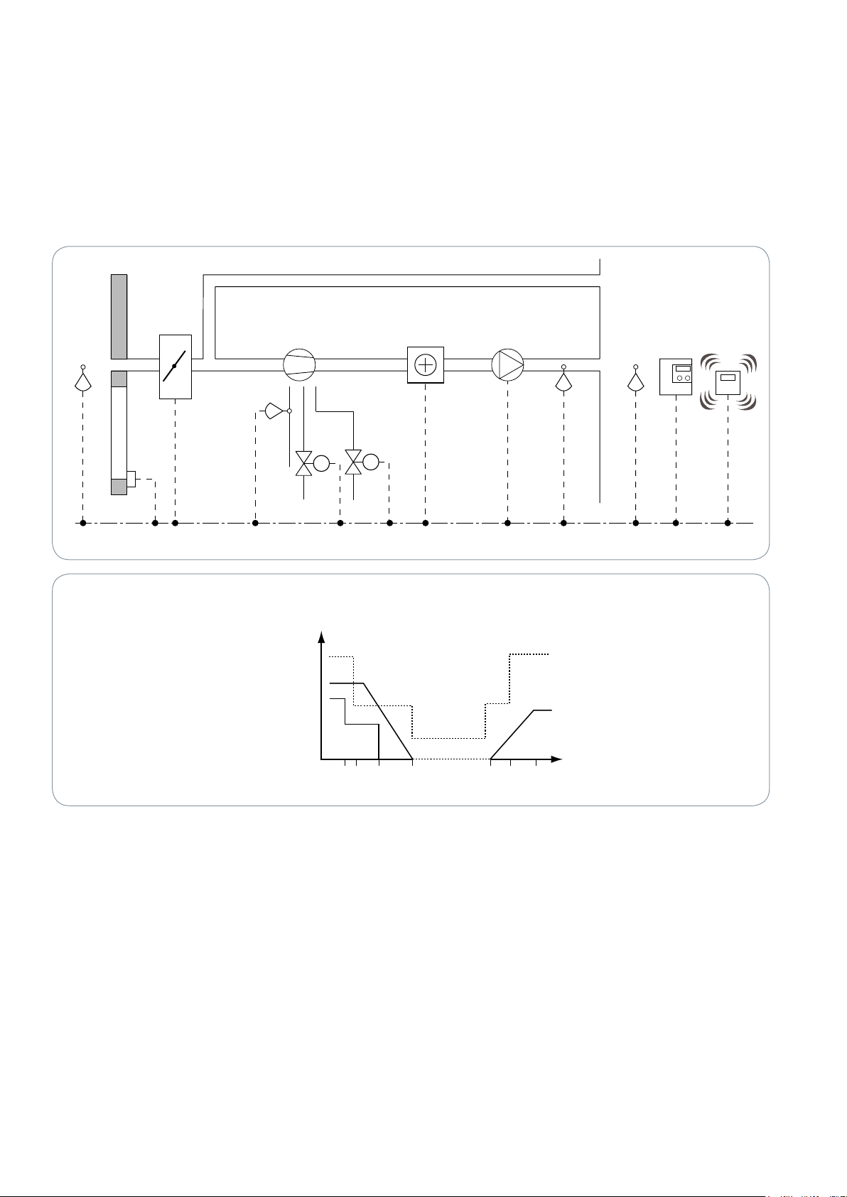
APPLICATION EXAMPLES
Window sensor
1-, 2- or
3-speed fan
Wall module
Occupancy sensor
Discharge air sensor
Reheating stage
Outside temp. sensor
Economizer
Heating/Cooloing
compressor
Isolation
valve
CO
2
sensor
Reversing
valve
Water temp.
sensor
Control sequence heat pump (example)
-100 -83 -50 0
0 33 100
Fan
Primary Heating
Secondary Heating
Output
signal
Cooling
Terminal
Load
TAC Xenta 121-HP can be programmed
to work with 1-3 compressors and an
optional second heating device, which
can have multistage, pwm, analog, or
increase/decrease control.
A Heat Pump unit can have a reversing
valve and an isolation valve (Fig. 1).
An electrical heater is common as the
second device.
The user defines the sequence; there are
no restrictions that a specific device be
activated first, in parallel, in series, or so
on.
Fan control outputs are always multi stage
output (1, 2 or 3 stages) or an analog
output.
Economizer control using an outside air
damper, as well as CO2 control and %RH
control are available.
When the temperature in the zone increa ses, the heat pump effect decreases,
see Fig. 2. If there is still a cooling demand, the reversing valve changes, the
heat pump effect increases, and the fan
speed increa ses in steps until the highest
fan speed is reached.
This sequen ce is reversed when the temperature drops.
Figure 1: HP with isolation and reversing valves
Figure 2

3
03-00135-04-en
CONTROL OPTIONS
The physical control options are as follows:
Multistage: up to three compressors
1–3 digital outputs are used to give up to
three levels of control. A special case of
this is one stage, which is just on/off.
Each stage is initiated at a configurable
load. Other configuration parameters
are: hysteresis, minimum cycle time, and
minimum inter-stage time.
It is configurable whether a lower stage
shall remain active when the next stage
is activated. To achieve an even wear, the
stages can be cycled.
The following options are mainly intended for the secondary heating, but may
also be used for the primary heating:
Analog, 0–10V
Incr/Decr (3-point)
Pulse Width Modulation
One digital signal gives a modulating
signal by using a variable duty cycle.
General
For the different types of control, different set-ups like scaling or signal limitation
values, hysteresis, timing, and so on can
be given.
Any type of control can be used with any
equipment, but some types are more suitable than others.
All control can be done either over physical outputs of the controller or on other
devices connected to the controller over a
LON® network.
Available I/O
3 digital inputs (X)
2 temperature inputs (B) NTC 1.8 kohm
1 universal input (U), temperature or
digital
1 pot.meter input (R) linear 10 kohm
4 Triac outputs (V): valve actuators or
other devices
4 relay outputs (K): Fan or other devices
1 analog output, 0-10 V (Y): analog or
LED
INSTALLATION
To satisfy regulatory safety requirements,
the controller must be built-in when line
voltage is connected.
It may be mounted on a DIN rail or
fastened onto a surface with screws.
There are two sockets provided for that
purpose.
Cable lengths
Communication cables: please refer to
the TAC Xenta Network Guide, part no.
0-004-7460.
CONFIGURATION OPTIONS
By selecting among the Configuration
Modules in the TAC ZBuilder, it is possible
to achieve diffe rent options in TAC Xen ta
121-HP for the following:
Space (Wall module) and outside tem-
perature sensors
Discharge (Supply) Air temperature sen-
sor
Water temperature sensor
Setpoint adjustment
Outside air damper (Economizer control)
Relative Humidity sensors, space and
outside
CO2 sensor
Bypass or On/Off button
Room temperature offset scaling
Occupancy sensor
Fan status
Window contact
Freeze protection
Alarm output
TAC Xenta OP can be used to inspect nvi
and nvo values. Due to the many configuration possibilities, it cannot be used
to configure the controller.
OTHER FUNCTIONS
Exception Modes
Exception Mode is a common name for
all kinds of situations where normal control no longer can be used.
Up to eight different exception modes
can be configured.
Each mode will have its predefined values
on heating devices one and two, cooling
device, fan status, speed, and outside air
damper. If applicable, it can also be connected to a digital output.
Each of the eight exception modes has its
own indicator in nvoSystemStatus.
When the exception mode situation
clears, it is possible to configure if it is
allowed to go out of the exception mode
and, if so, the delay before normal control
is resumed.
Examples where exception modes are
useful:
Window contact
Smoke input
Freeze protection
Morning warm-up
Compressor (abort)
Resync
All outputs configured as inc/dec outputs
will have a cyclic resync interval of 18 h.
Resync can also be initiated via nviDOResync. It is configurable to synchronize toward open or closed position.
Installations Test – Checkout Mode
To facilitate the testing and installation,
it is possible to override the physical outputs. By setting a certain status override
SNVT, all outputs will be controlled by
the user, who can test them freely. No fan
interlock or other logical conditions will
be activated.
Forcing the Space temp makes it possible
to verify the sequence.
Unused Digital Inputs and Outputs
Some digital outputs will have a SNVT
input, which allows any other LON device
to control these digital outputs.
A condition is that the application is not
using the output. Some unused inputs
will have the same functionality, using a
SNVT output.
Not all digital inputs/outputs can have a
mirror SNVT, due to the limitation of the
SNVTs. If feasible, the same will be applied for analog in/outputs.
Flexible Combinations
By using TAC ZBuilder stand-alone on
a PC, you can easily explore the many
features and the great versatility of this
product.
Please refer to the TAC ZBuilder data
sheet 0-003-3010 for further details
about the easy way to program your
TAC Xenta 121.

4
03-00135-04-en
Lo n Ma r k OBJECTS AND NETWORK VARIABLES
0 - Node Object
Object Type: 0
Mandatory
Network
Variables
Optional
Network
Variables
Configuration Properties
(The Configuration parameters are all handled by the Tool.)
nviRequest
SNVT_obj_request
nvoStatus
SNVT_obj_status
nvoFileDirectory
SNVT_address
nv1
nv2
nv8
Additionally, the following objects are used, all with their configuration parameters handled by TAC ZBuilder:
Config. Param. Description
20023 Application Object
20024 Control Object
20026 Fan Object
20028 I/O Object
20025 Temperature Control Device Object
20027 Exception Mode Object
Figure 3
Figure 4

5
03-00135-04-en
HARDWARE INTERFACE
mm (in.)
No. Designation Description
1 X2 Input, digital
2 M Measurement neutral
3 X3 Input, digital
4 B2 Input, temperature sensor
5 Y1 Output, analog
6 M Measurement neutral
7 X1 Input, digital
8 R1 Input, setpoint offset dial on wall module
9 M Measurement neutral
10 B1 Input, temperature sensor
11 K4 Output, relay 4
12 KC2 Relay 4, common
13 G0 or N See 14
14 G or L HP/24: 24 V AC Supply
HP/230: Mains Supply
OP TAC Xenta OP RJ-10 access
connector
DIMENSIONS
No. Designation Description
15 C1 TP/FT-10 communication channel
16 C2 See above
17 M Measurement neutral
18 U1 Input, temp. sensor/digital/analog
19 V1 Output, Triac 24 V AC
20 G 24 V AC (L) output for V1 and V2
21 V2 Output, Triac 24 V AC
22 V3 Output, Triac 24 V AC
23 G 24 V AC (L) output for V3 and V4
24 V4 Output, Triac 24 V AC
25 K3 Output, relay 3
26 K2 Output, relay 2
27 K1 Output, relay 1
28 KC1 Relay 1-3, common
Figure 5
ROOM UNITS
The STR is a series of wall modules optimized for public facilities such as office buildings, hotels, hospitals, schools, and shopping malls.
The following room units can be configured with the TAC Xenta 121-HP.
Model Temp.
Sensor
STR100 X
Mode
Indicator
Setpoint
Offset
Bypass
Button
Fan
Speed
Control
Back
Light
SNVT
Binding
Required
STR101 X X
STR102 X X X
STR103 X X X
STR104 X X X X
STR106 X X X X X*
STR107 X X X X X**
STR150 X X X X X***
STR350 X X X X X*** X
STR351 X X X X X*** X X
PART NUMBERS
STR100 .................004600100
STR100-W (White) ........004600110
STR101 .................004600200
STR102 .................004600300
STR103 .................004600700
STR104 .................004600400
STR106 .................004600500
STR107 .................004600600
STR150 .................004602800
LON Modules
STR350 .................004605000
STR351 .................004605100
* STR106 Fan speed: Auto-0-I-II-III
** STR107 Fan speed: Auto-Off-On
*** STR150, 350/351 Fan speed: configurable

Copyright © 2008-2012, Schneider Electric
All brand names, trademarks and registered trademarks are
the property of their respective owners. Information contained
within this document is subject to change
without notice. All rights reserved.
03-00135-04-en Feb 2012
 Loading...