

Page 1

TAC Vista
TAC Pangaea
WorkStation
TAC Xenta 120
Technical Manual
Page 2

Page 3

TAC Vista
TAC Xenta 120
Technical Manual
Page 4

Copyright © 2011 Schneider Electric Buildings. All rights reserved.
This document, as well as the product it refers to, is only intended for licensed users. Schneider Electric Buildings owns the copyright of this
document and reserves the right to make changes, additions or deletions. Schneider Electric Buildings assumes no responsibility for possible
mistakes or errors that might appear in this document.
Do not use the product for other purposes than those indicated in this document.
Only licensed users of the product and the document are permitted to use the document or any information therein. Distribution, disclosure,
copying, storing or use of the product, the information or the illustrations in the document on the part of non-licensed users, in electronic or
mechanical form, as a recording or by other means, including photo copying or information storage and retrieval systems, without the express
written permission of Schneider Electric Buildings, will be regarded as a violation of copyright laws and is strictly prohibited.
Trademarks and registered trademarks are the property of their respective owners.
Page 5

TAC Xenta, TAC Xenta 120 Contents
Contents
INTRODUCTION
1 About this Manual 11
1.1 Structure..................................................................................................................... 11
1.2 Typographic Conventions.......................................................................................... 12
1.3 Prerequisites............................................................................................................... 12
1.4 Terminology............................................................................................................... 13
GETTING STARTED
2 Planning the Project 19
2.1 Folder Structure.......................................................................................................... 19
2.1.1 Creating a Project Folder ........................................................................................... 19
2.2 Case Study.................................................................................................................. 20
2.2.1 Description of Facility................................................................................................ 20
2.2.2 Device Description and Naming Convention ............................................................ 21
2.2.3 Devices in the Example.............................................................................................. 22
2.2.4 Network Structure and Naming Convention in the Example..................................... 23
3 Creating the TAC Xenta 120 Configuration 25
3.1 ZBuilder Example Overview ..................................................................................... 25
3.2 Starting ZBuilder.......................................................................................... .... ..... ..... 25
3.3 Selecting a Template.................................................................................................. 26
3.4 Adjusting the Configuration....................................................................................... 26
3.4.1 Adjusting the Heating/Cooling Parameters................................................................ 27
3.4.2 Adjusting the Fan Parameters .................................................................................... 29
3.4.3 Adding a Room Unit.................................................................................................. 30
3.4.4 Adding an Occupancy Signal..................................................................................... 31
3.4.5 Adding a Window Contact......................................................................................... 32
3.4.6 Adjusting the Control Parameters for the Fan............................................................ 33
3.5 Specifying an Exception Mode.................................................................................. 34
3.6 Changing the Inputs/Outputs configuration............................................................... 35
3.7 Documenting and Saving the Configuration.............................................................. 37
3.7.1 Documenting the Configuration on a Printout........................................................... 37
3.7.2 Saving the Configuration File.................................................................................... 38
4 Installing TAC Xenta 120 in a Classic Network 39
4.1 Adding and Configuring the TAC Xenta 120............................................................ 39
4.1.1 Adding a LonWorks Group........................................................................................ 39
4.1.2 Adding a TAC Xenta 120 .......................................................................................... 40
4.1.3 Configuring a TAC Xenta 120................................................................................... 42
Schneider Electric Buildings, Dec 2011 5 (126)
04-00035-02-en (EN)
Page 6

Contents TAC Xenta, TAC Xenta 120
4.2 Commissioning and Downloading ............................................................................. 45
REFERENCE
5 ZBuilder - the Configuration Tool 49
5.1 Usage.......................................................................................................................... 49
5.2 ZBuilder Overview........................................................................................ .... ..... .... 49
5.3 Templates and Applications ....................................................................................... 52
5.3.1 Selecting a File ...........................................................................................................52
5.4 The Configuration Window........................................................................................ 52
5.5 Documenting the Configuration................................................................................. 53
5.5.1 Printing the Configuration Parameters....................................................................... 53
5.5.2 Associating a Graphic with the Configuration........................................................... 54
5.5.3 Saving the Configuration............................................................................................ 55
6 TAC ZBuilder as a Plug-in 57
6.1 As a Plug-in in TAC Vista.......................................................................................... 57
6.1.1 Starting ZBuilder from TAC Vista............................................................................. 57
6.1.2 Resetting a Neuron ..................................................................................................... 58
6.2 As a Plug-in in LonMaker.......................................................................................... 58
6.2.1 Starting ZBuilder from LonMaker ............................................................................. 58
6.2.2 Configuring a TAC Xenta 120................................................................................... 59
6.2.3 Updating a LonMaker Device Shape ......................................................................... 60
6.2.4 Registering ZBuilder as a Plug-in ............................................... ............................... 61
6.2.5 Resetting a Neuron ..................................................................................................... 62
7 Application Types (Configuration) 63
7.1 Terminal Load and the Heating/Cooling Sequence.................................................... 63
7.2 The 4-pipe Fan-Coil ................................................................................................... 64
7.3 The 2-pipe Fan-Coil ................................................................................................... 64
7.4 The Heat Pump........................................................................................................... 65
7.5 Different Control Signals ........................................................................................... 66
7.6 Peripheral Units and Additional Functions ................................................................ 70
8 Fan Control 71
8.1 General ....................................................................................................................... 71
8.2 Analog Control........................................................................................................... 71
8.3 On/off and Multistage Control ............................................... ..... .... ..... ...................... 72
8.4 Fan Hysteresis ............................................................................................................ 72
8.5 Other Fan Parameters ................................................................................................. 72
8.5.1 Boost........................................................................................................................... 72
8.5.2 Conditioning...............................................................................................................72
8.5.3 Cooling delays........................... ..... .... ...................................................... .................. 73
8.5.4 Heating delays ............................................................................................................ 73
8.5.5 Feedback..................................................................................................................... 73
8.5.6 Interlock...................................................................................................................... 73
8.5.7 Run in deadband................................. ..... .... ...................................................... ..... .... 74
8.6 Fan Control from STR Wall units .............................................................................. 74
9 Connected Devices and Network Parameters 75
9.1 Room Unit .................................................................................................................. 75
9.1.1 STR Modules: I/O Usage ........................................................................................... 76
6 (126) Schneider Electric Buildings, Dec 2011
04-00035-02-en (EN)
Page 7

TAC Xenta, TAC Xenta 120 Contents
9.1.2 STR Modules: Additional functions .......................................................................... 76
9.2 Occupancy sensor....................................................................................................... 76
9.3 Window Contact......................................................................................................... 77
9.4 Air Quality Equipment............................................................................................... 77
9.4.1 OAD, Outside Air Damper ........................................................................................ 78
9.4.2 CO
Control......................................................................................... .... ..... .............. 78
2
9.4.3 Dehumidification, %RH............................................................................................. 78
9.4.4 Economizer ................................................................................................................ 79
9.5 Free I/O ...................................................................................................................... 80
9.5.1 General....................................................................................................................... 80
9.5.2 Push-button Signals.................................................................................................... 81
9.6 L
ON Properties.......................................................... .... ..... ......................................... 82
9.6.1 Node........................................................................................................................... 82
9.6.2 SNVT ......................................................................................................................... 83
9.6.3 Common SNVT Properties .......................................................................... .... ..... ..... 84
10 Control Issues 85
10.1 Room Temperature Setpoints..................................................................................... 85
10.2 PI parameters........................................................................................... ..... .... .......... 86
10.3 Cascade control.......................................................................................................... 88
10.4 Master-Slave Considerations ..................................................................................... 89
10.5 Actuator Resync and End-points Adjustment............................................................ 90
11 Exception Modes 93
11.1 General....................................................................................................................... 93
11.2 Exception Mode Activation ....................................................................................... 93
11.3 Status when Active..................................................................................................... 95
11.4 Reset Condition.......................................................................................................... 96
11.5 “Other events” explained ........................................................................................... 96
11.5.1 Compressor Lock-out................................................................................................. 96
11.5.2 Fan feedback failure................................................................................................... 96
11.5.3 Flow feedback error ................................................................................................... 97
11.5.4 Loss of space temp input signal ................................................................................. 97
11.5.5 Loss of water temp input signal ................................................................................. 97
11.5.6 Bypass button used as on/off set to off ...................................................................... 97
11.5.7 Exception Mode status............................................................................................... 97
11.6 Some Exception Mode Examples .............................................................................. 98
12 I/O Setup 103
12.1 Hardware Platforms ................................................................... .... ............................ 103
12.2 Digital Input Polarity.................................................................................................. 103
12.3 I/O Ports ..................................................................................................................... 104
12.3.1 Default Usage.............................................................................................................104
12.3.2 Re-arranging the Ports................................................................................................ 104
12.4 Functions Bound to SNVTs....................................................................................... 104
12.5 Temperature Offsets................................................................................................... 105
Schneider Electric Buildings, Dec 2011 7 (126)
04-00035-02-en (EN)
Page 8

Contents TAC Xenta, TAC Xenta 120
APPENDIX
A Setpoint Calculation 109
B SNVT-lists 113
B.1 The Node Object Inputs and Outputs (nvi, nvo) ........................................................ 113
B.2 The Control Object Inputs (nvi)................................................................................. 113
B.3 The Control Object Outputs (nvo).............................................................................. 117
Index 121
8 (126) Schneider Electric Buildings, Dec 2011
04-00035-02-en (EN)
Page 9

INTRODUCTION
1 About this Manual
Page 10

Page 11

TAC Xenta, TAC Xenta 120 1 About this Manual
1 About this Manual
This manual describes a particular process. For information on certain
products, we refer you to the manual or the Help for the product in question.
For information on how to install software, we refer you to the instructions delivered with the software.
For information on third party products, we refer you to the instructions
delivered with the third party product.
If you discover errors and/or unclear descriptions in this manual, please
contact your TAC representative.
Note
1.1 Structure
We are continuously improving and correcting our documentation.
This manual may have been updated.
Please check our product documentation site at www.tac.com for the
latest version.
The manual is divided into the following parts:
• Introduction
The Introduction section contains information on how this manual
is structured and how it should be used to find information in the
most efficient way.
• Getting Started
The Getting Started section contains a step-by-step description of
how to engineer or carry out different tasks. It also gives you
guided instructions on how to complete a sample project. If you
want more information, see the corresponding chapter in the Reference section of the manual.
• Reference
The Reference section contains more comprehensive information
about various parts of the Getting Started section. It also provides
you with information on alternative solutions not covered by the
Getting Started section.
• Appendix
At the end of the manual we have collected some detailed descrip-
Schneider Electric Buildings, Dec 2011 11 (126)
04-00035-02-en (EN)
Page 12
1 About this Manual TAC Xenta, TAC Xenta 120
!
tions and lists. This information may be useful during special circumstances, but is normally not required.
1.2 Typographic Conventions
Throughout the manual the following specially marked texts may occur.
Warning
Alerts you that failure to take, or avoid, a specific action might result
in physical harm to you or to the hardware.
Caution
Alerts you to possible data loss, breaches of security, or other more
serious problems.
Important
Alerts you to supplementary information that is essential to the completion of a task.
Note
Alerts you to supplementary information.
Tip
Alerts you to supplementary information that is not essential to the
completion of the task at hand.
Advanced
Alerts you that the following information applies to complex tasks or
tasks restricted by access.
1.3 Prerequisites
To be able to profit from the contents in this manual, it is recommended
that you read the following documentation:
• TAC ZBuilder Programming Tool for TAC Xenta 120, Datasheet,
0-003-3010.
12 (126) Schneider Electric Buildings, Dec 2011
04-00035-02-en (EN)
Page 13

TAC Xenta, TAC Xenta 120 1 About this Manual
• TAC Xenta 121-FC Programmable Fan Coil Application,
Datasheet, 0-003-3057.
• TAC Xenta 121-HP Programmable Heat Pump Application,
Datasheet, 0-003-3058.
• TAC Xenta 121/24 24 VAC Hardware Platform Installation
Instruction, 0FL-4234.
• TAC Xenta 121/230 230 VAC Hardware Platform Installation
Instruction, 0FL-4235.
• TAC Vista IV Engineering Classic Networks, manual, 0-004-7841.
• TAC Vista IV Engineering LNS Network, manual, 0-004-7842.
1.4 Terminology
TAC Xenta Devices
• All programmable T AC Xentas, 280/300/401, will be called Xenta
devices throughout this manual.
• The Xenta 422, 452, and so on will be referred to as I/O modules.
LonWorks Devices
• All other devices will be called LonWorks devices, including the
Xenta 100.
Classic Network
•A Classic Network refers to a TA C Vista system with a Lon-
Works network, TAC Xenta devices and/or LonWorks devices,
using an LTA port connection/communication to the network and
no LNS database. A Classic Network does NOT use any SNVT
bindings.
LNS Network
•An LNS Network refers to a TAC Vista system with a LonWorks
network, TAC Xenta devices and/or LonWorks devices, using an
LTA port with a VNI as the Network Interface (NI) application,
LonMaker 3 and an LNS database. This type of LTA port is
referred to as an LNS port in TAC Vista IV.
TAC Vista Modes
• Engineering Mode. This mode is used when commissioning the
network. In this mode, you can send information to the network
devices as well as service pin each device.
• Operating Mode. This mode provides full communication
between the server and the network device. If the connection
between the server and the device on the network is disrupted, you
will receive an alarm.
Schneider Electric Buildings, Dec 2011 13 (126)
04-00035-02-en (EN)
Page 14

1 About this Manual TAC Xenta, TAC Xenta 120
Some useful terms and abbreviations regarding the zone controller's
application and network communication are explained in the table
below.
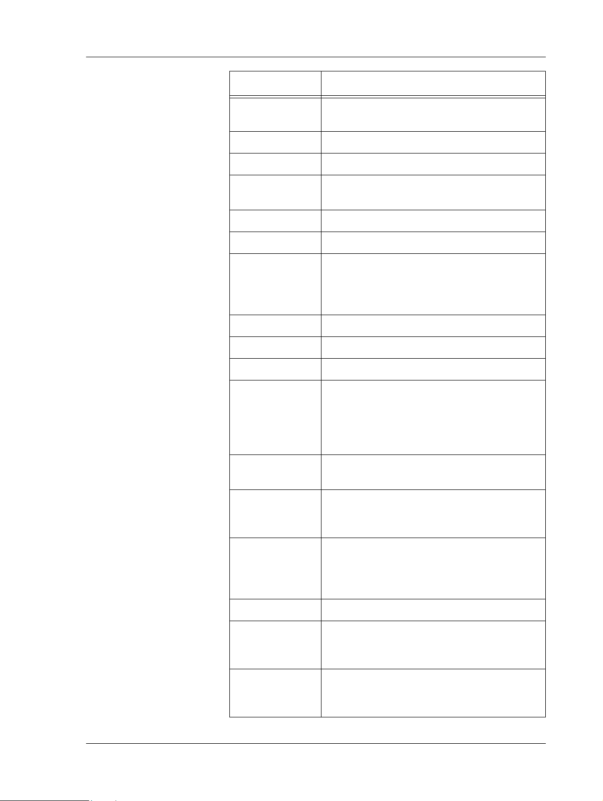
Term Description
ASC Application Specific Controller
CCD Climate Control Device
CFR Configuration record, a file included with the
XIF file for devices with many configuration
parameters. Example: TAC Xenta 120 series.
configuration Procedure to design the software for an ASC
DAT Discharge Air Temperature
device plug-in TAC Vista: controller configuration tool
LNS: application to provide custom user inter-
face for devices.
FB Functional Block
Exception Mode Special, configurable behavior of the controller
triggered by certain events.
hardwired an I/O that is physically connected, as opposed
to a SNVT binding
HP Heat Pump
FC Fan Coil
I/O Input/Output
LNS L
ONWORKS Network Servic es; network man-
agement software for L
ONWORKS networks
MS MultiStage
nci configuration parameter; variable that gets its
value from a configuration tool and keeps it
during a power failure
Neuron A microprocessor optimized for control net-
works. Neuron chips have three 8-bit inline
processors: two are dedicated to the communi-
cations protocol and one is a general-purpose
applications processor.
nvi variable that normally gets its value from
another unit on the network through binding
14 (126) Schneider Electric Buildings, Dec 2011
04-00035-02-en (EN)
Page 15
TAC Xenta, TAC Xenta 120 1 About this Manual
Term Description
nvo variable that is sent to another unit on the net-
work
OAD Outside Air Damper
OAT Outside Air Temperature
PWM (Pulse Width Modulat ion) One type of actuator
control signal
SCC Space Comfort Controller
scpt Standard Configuration Property Type
sequence dia-
gram
A diagram with the Terminal Load on the x-
axis and the (symbolical) controller output sig-
nals on the y-axis. The principal usage of the
TCDs depending on the TL value is shown.
SPID Standard Program ID
SNVT Standard Network Variable Type
STR Room temperature sensor (STR series)
stand-alone The T AC ZBuilder does not run directly ag ainst
a controller or as a plug-in. Generated configu-
rations can only be saved to a file, not down-
loaded to a physical controller or saved to a
database.
TCD Temperature Control Device - Heating and/or
cooling equipment
template A standard configuration file that can be used
as a starting-point for a specific ZBuilder appli-
cation. File name: *.zbt.
TL,
Terminal Load
Terminal Load is a value in the range –100% to
+100%. The value indicates the amount of
power (<0: heating, >0: cooling), needed to
reach the required temperature.
ucpt User Configuration Property Type
XFB-file / XFO-
file
When the XIF-file is imported to L
ONMAKER
Integration Tool it is compiled into two files:
the XFB-file and the XFO-file.
XIF file eXternal InterFace file is a file that, in short,
describes which network variables the device
can handle.
Schneider Electric Buildings, Dec 2011 15 (126)
04-00035-02-en (EN)
Page 16

1 About this Manual TAC Xenta, TAC Xenta 120
Term Description
.zbc File name extension for ZBuilder configuration
files.
.zbt File name extension for ZBuilder template
files. See also template.
16 (126) Schneider Electric Buildings, Dec 2011
04-00035-02-en (EN)
Page 17

GETTING STARTED
2 Planning the Project
3 Creating the TAC Xenta 120 Con-
figuration
4 Installing TAC Xenta 120 in a
Classic Network
Page 18

Page 19
TAC Xenta, TAC Xenta 120 2 Planning the Project
2 Planning the Project
Planning the LonWorks Network in advance saves a lot of time and
effort later in the process. Issues like network structure (groups),
device-naming conventions, and so on should be considered before
actually creating the network.
2.1 Folder Structure
Another consideration is the location(s) on the hard drive where files are
stored. A well-organized project requires a well-organized file structure.
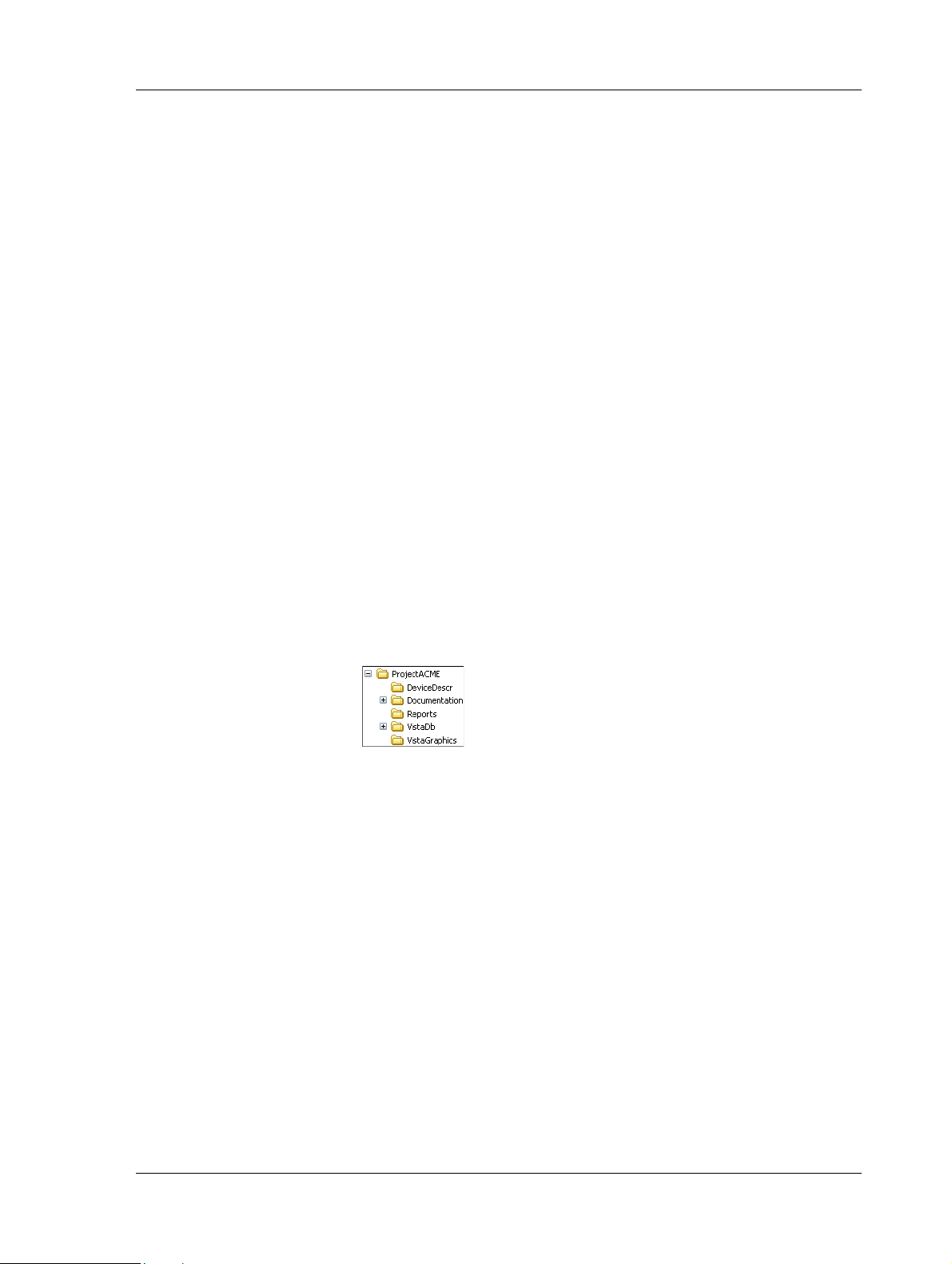
2.1.1 Creating a Project Folder
When starting a new project, you should prepare a directory containing
folders and subfolders as shown below. In this example, we call our
project ACME.
A short description of their intended use and content:
• DeviceDescr – *.mta-files and *.xif-files for the LonWorks net-
work devices.
• Documentation – subfolder with more general information. For
example, useful manuals, data sheets, and technical product information (TPI). I/O-lists, functional descriptions, and other files created by DesignBuilder could also be saved here.
• Reports – reports from Vista Server.
• VistaDb – the Vista database.
• VistaGraphics – Vista graphics files.
Once the engineering work is finished, the complete project folder is
transferred from the engineering PC to the site PC. Save the folder
structure as a compressed file (*.zip) to avoid problems with the readonly attributes when storing on a CD.
Schneider Electric Buildings, Dec 2011 19 (126)
04-00035-02-en (EN)
Page 20

2 Planning the Project TAC Xenta, TAC Xenta 120
2.2 Case Study
The following chapters describe how to configure and add a TAC Xenta
120 to a LonWorks network using TAC ZBuilder. Our network example is based on the case described below.
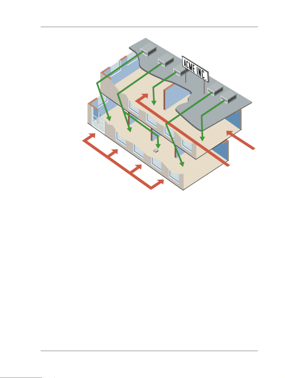
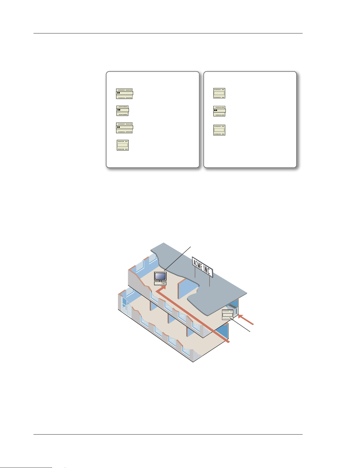
2.2.1 Description of Facility
We are creating a system for a fictional company that we call ACME
Inc.
The facility is a typical, small two-story office building, served by packaged rooftop equipment. The first floor area serves Marketing,
Accounts, Senior Management and the entrance lobby. The second
floor area serves Engineering and Customer Support.
Within the first floor area, the Accounting area is served by a constant
volume rooftop air handling unit. This unit has central station cooling
and central station heating. The space is divided into control zones; the
Accounting area and a conference room with secondary air handling.
The Marketing and Senior Management areas are served by a single
rooftop variable air volume (VAV) air handling unit. The first floor
lobby area is served by a rooftop constant-volume single zone air handling unit.
On the second floor, the Customer Support area is served by a single
zone, rooftop constant-volume air handling unit. The Engineering area
is served by a Rooftop VAV air handling unit. A laboratory within the
engineering area is temperature-controlled by a fan-coil unit. The staff
can supervise the system from a PC-based presentation system.
20 (126) Schneider Electric Buildings, Dec 2011
04-00035-02-en (EN)
Page 21
TAC Xenta, TAC Xenta 120 2 Planning the Project
RTU1
RTU3
RTU2
RTU4
Engineering
Support
Lobby
Accounts
Conference Room
Marketing and Management
Lobby
Conf_Room
2.2.2 Device Description and Naming Convention
Within the first floor area, the rooftop unit serving the Accounting area
is controlled by a Xenta 301, called RTU1.
The secondary air handling unit serving Marketing and Senior Management is controlled by a Xenta 281, called Conf_Room.
The rooftop unit serving Marketing and Senior Management is controlled by a Xenta 401, called RTU2, using four I/O modules.
The air handling unit serving the lobby area is controlled by a Xenta
104, called Lobby.
Within the second floor area, the rooftop unit serving the Customer Support area will be controlled by a Xenta 104, named RTU3.
The rooftop unit serving the Engineering area is controlled by a Xenta
401, called RTU4, using five I/O modules.
The fan-coil unit in the engineering lab area is controlled by a Xenta
121-FC, called Engr_Lab, configured with TAC ZBuilder.
Schneider Electric Buildings, Dec 2011 21 (126)
04-00035-02-en (EN)
Page 22
2 Planning the Project TAC Xenta, TAC Xenta 120
First Floor Second Floor
RTU1
Xenta 301
Conf_Room
Xenta 281
Lobby
Xenta 104
RTU3
Xenta 104
RTU4
Xenta 401
RTU2
Xenta 401
Engr_Lab
Xenta 121-FC
VistaSRV1
Engr_lab
The PC where the presentation system is installed is called VistaSRV1
(in some pictures called VistaSrv_1, but the character “_” should be
avoided) and is located in the Support area.
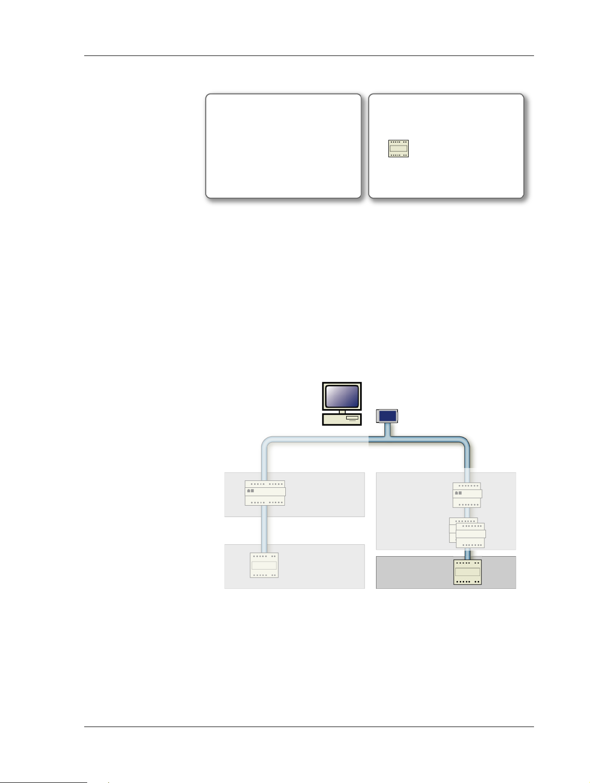
2.2.3 Devices in the Example
In our example, we use a part of the above network to illustrate how a
Xenta 120 is added.
On the second floor, we have selected the engineering lab fan-coil unit
to illustrate how to configure and install a TAC Xenta 120.
22 (126) Schneider Electric Buildings, Dec 2011
04-00035-02-en (EN)
Page 23
TAC Xenta, TAC Xenta 120 2 Planning the Project
First Floor Second Floor
Engr_Lab
Xenta 121-FC
RTU4
Xenta 401
VistaSRV1
LTA Card
I/O Modules
(1 & 3)
Conf_Room
Lobby
LonWorks Group 1st_Floor_LW
Xenta Group 1st_Floor
Xenta Group 2nd_Floor
LonWorks Group 2nd_Floor_LW
Engr_Lab
We work with the following device:
2.2.4 Network Structure and Naming Convention in the Example
When adding the Xenta 120 using Vista Workstation, the name of the
network is the name of the company – ACME_Inc. Since the building
has two floors, the network is built with the devices divided into two
Xenta groups called 1st_Floor and 2nd_Floor.
Xenta devices placed on the first floor belong to the Xenta group
1st_Floor and Xenta devices placed on the second floor belong to the
Xenta group 2nd_Floor.
The Xenta 104 is a member of the LonWorks group 1st_Floor_LW and
the Xenta 121-FC is a member of the LonWorks group 2nd_Floor_LW.
Schneider Electric Buildings, Dec 2011 23 (126)
04-00035-02-en (EN)
Page 24

2 Planning the Project TAC Xenta, TAC Xenta 120
24 (126) Schneider Electric Buildings, Dec 2011
04-00035-02-en (EN)
Page 25

TAC Xenta, TAC Xenta 120 3 Creating the TAC Xenta 120 Configuration
3 Creating the TAC Xenta 120
Configuration
3.1 ZBuilder Example Overview
ZBuilder is a software tool designed to create a set of configuration
parameters for a specific application, for example a fan-coil with an
electric reheater or a heat pump with a reversing valve.
The parameters are saved in a configuration file which is used by TAC
Vista or LonMaker to install and commission the corresponding TAC
Xenta 120 controller.
For a thorough description of the tool and the working methods, please
refer to Chapter 5, “ZBuilder - the Configuration Tool”, on page 49, and
the other chapters in the Reference section of the manual.
In this chapter you will learn how to use ZBuilder to:
• Start ZBuilder stand-alone
• Select a configuration template
• Adjust the Configuration
• Specify an Exception Mode
• Configure the Inputs/Outputs
• Save and Document the Configuration
3.2 Starting ZBuilder
ZBuilder can be run stand-alone, but can also be started as a plug-in
from TAC Vista or L
To start ZBuilder as a plug-in, the Xenta 120 must be added to a LonWorks network:
• For more information on how to start ZBuilder as a plug-in from
Vista Workstation, see Section 6.1.1, “Starting ZBuilder from
TAC Vista”, on page 57.
• For more information on how to start ZBuilder as a plug-in from
LonMaker, see Section 6.2.1, “Starting ZBuilder from LonMaker”, on page 58.
ONMAKER.
Schneider Electric Buildings, Dec 2011 25 (126)
04-00035-02-en (EN)
Page 26
3 Creating the TAC Xenta 120 Configuration TAC Xenta, TAC Xenta 120
In the example, we start ZBuilder stand-alone to create the configuration file before the Xenta 120 is added to the Lonworks network.
To start ZBuilder as a stand-alone tool
• Click Start, point to All Programs, point to T A C, point to
TAC ZBuilder, and then click TAC ZBuilder.
The TAC ZBuilder Select File window now opens.
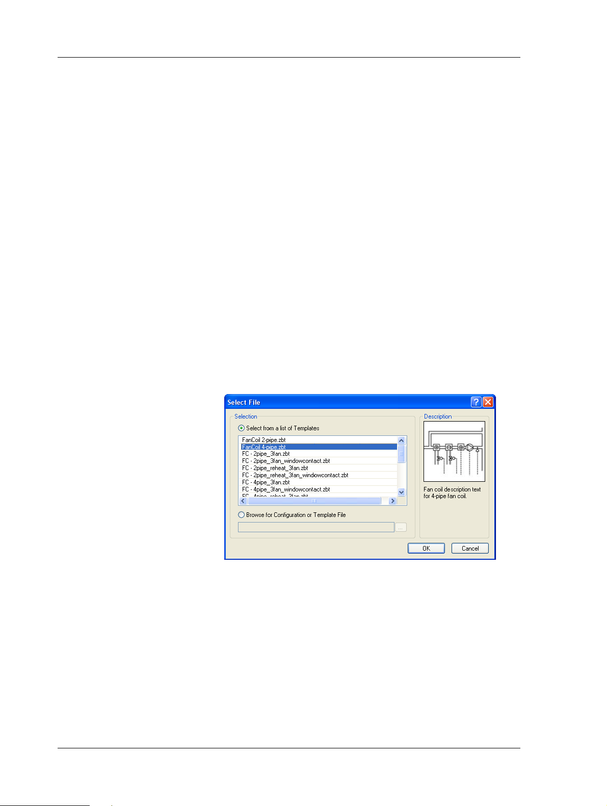
3.3 Selecting a Template
To simplify the configuration procedure, you start with a template or
another configuration file similar to the application that you are going
to create.
For more information on how to select files, see Chapter 5.3.1, “Selecting a File”, on page 52.
In the example, you will start with a template for a 4-pipe fan-coil.
To select a Template
1 In the Select File dialog box, make sure the Select from a list of
Templates option is selected.
2 In the templates list select the required template. In the example,
FanCoil 4-pipe.zbt.
3 Click OK.
3.4 Adjusting the Configuration
Normally you need to adjust the default configuration for the current
application.
In the example, we will adjust the settings to achieve the following:
• The fan will always run for at least 30 seconds when the second
heating stage is turned off.
• When the window is opened, the controller will be turned off.
26 (126) Schneider Electric Buildings, Dec 2011
04-00035-02-en (EN)
Page 27
TAC Xenta, TAC Xenta 120 3 Creating the TAC Xenta 120 Configuration
• The secondary heating will start at 80% Terminal Load.
• The second fan stage will start at 70% Terminal Load in cooling.
• The Occupancy state will be signalled via a SNVT; all other
inputs/outputs will be hardwired, that is, physically connected.
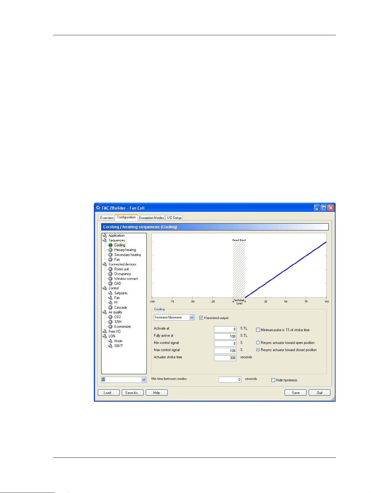
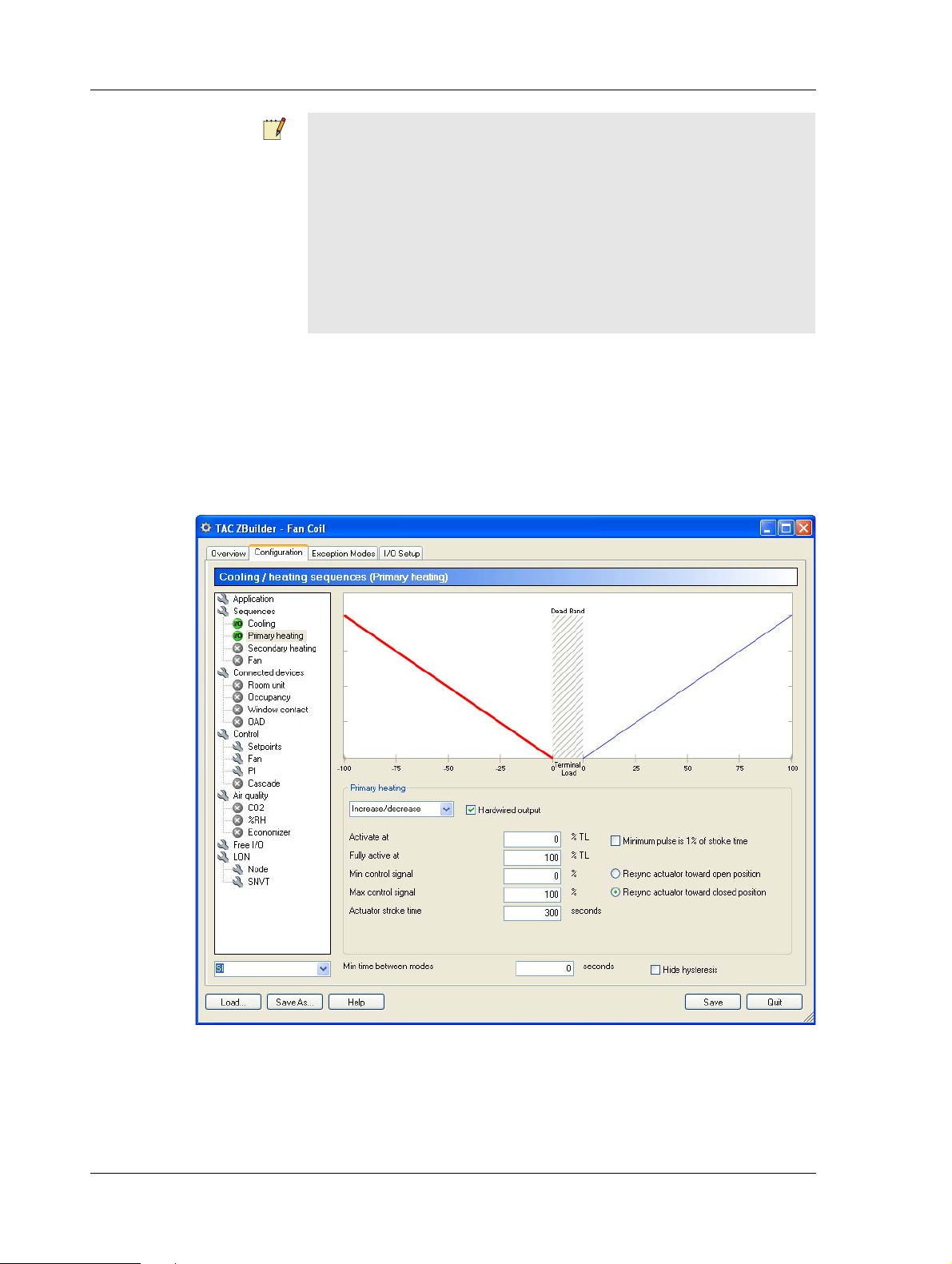
3.4.1 Adjusting the Heating/Cooling Parameters
For more information on the control sequence, see Chapter 7.1, “Terminal Load and the Heating/Cooling Sequence”, on page 63.
To adjust the Heating/Cooling Parameters
1 Click the Configuration tab.
2 In the tree structure, select Sequences\Cooling.
3 In the Cooling area, in the device type list, select the required
device type. In the example, Increase/decrease
4 Make sure the Hardwired output checkbox is selected.
Schneider Electric Buildings, Dec 2011 27 (126)
04-00035-02-en (EN)
Page 28
3 Creating the TAC Xenta 120 Configuration TAC Xenta, TAC Xenta 120
Notes
• Increase/decrease actuators need to be resynchronized. This can
be done towards the open or closed position. The specified direction will be used for all active increase/decrease actuators in the
configuration. The default value is Resync actuator towa rd
closed position. For more information, see Section 10.5, “Actuator Resync and End-points Adjustment”, on page 90.
• The Cooling icon in the tree to the left has been changed to a
green I/O icon.
You will now have a blue sloping line, showing how the valve will
open with increasing Terminal Load (increasing need of cooling).
5 In the tree structure, select Sequences\Primary heating.
6 In the Primary heating area, in the device type list, select the
required device type. In the example, Increase/decrease.
7 Make sure the Hardwired output checkbox is selected.
Note that you will get a red sloping line, showing how the valve
will close with increasing Terminal Load (decreasing need of heating).
28 (126) Schneider Electric Buildings, Dec 2011
04-00035-02-en (EN)
Page 29
TAC Xenta, TAC Xenta 120 3 Creating the TAC Xenta 120 Configuration
8 In the Fully active at box, enter the required value. In the exam-
ple, “80”.
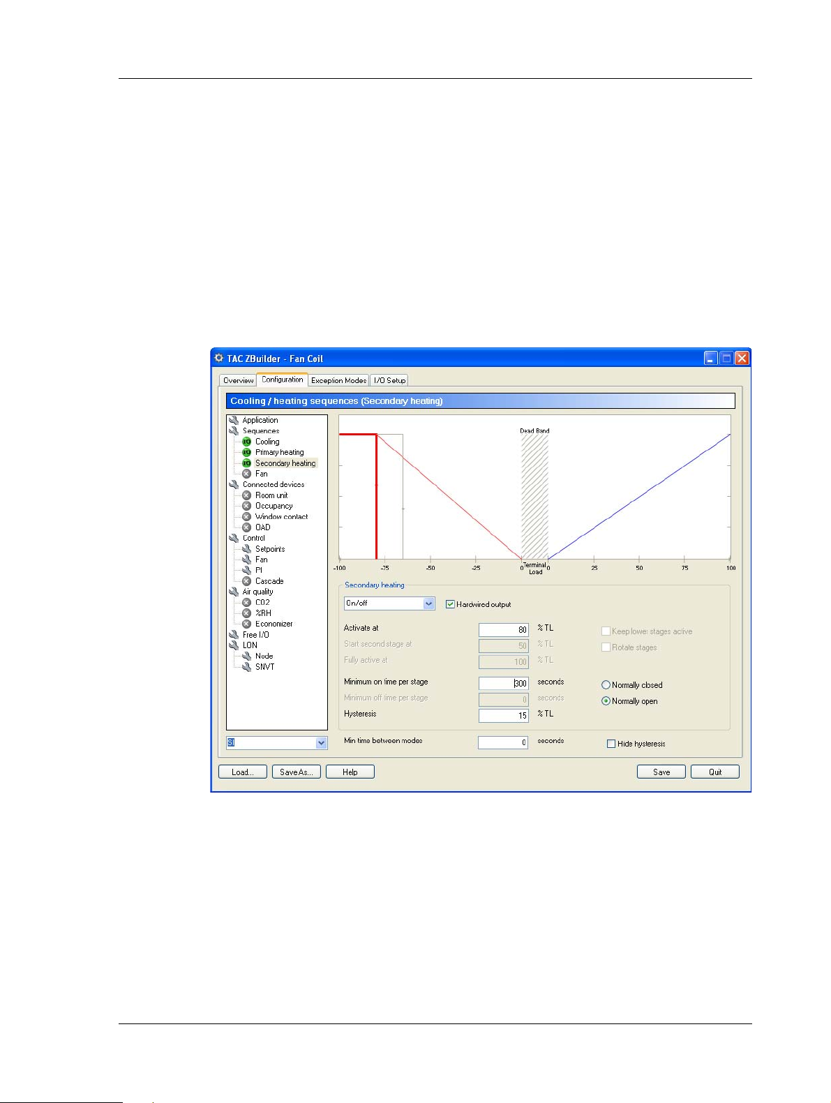
9 In the tree structure, select Sequences\Secondary heating.
10 In the Secondary heating area, in the device type list, select the
required device type. In the example, On/off to include the On/off
reheater.
11 Select the Hardwired output checkbox.
12 In the Activate at box, enter the required value. In the example,
“80”, to determine at what point the reheater will turn on.
13 In the Hysteresis box, enter the required value. In the example,
“15”, to determine the hysteresis before the reheater is turned off.
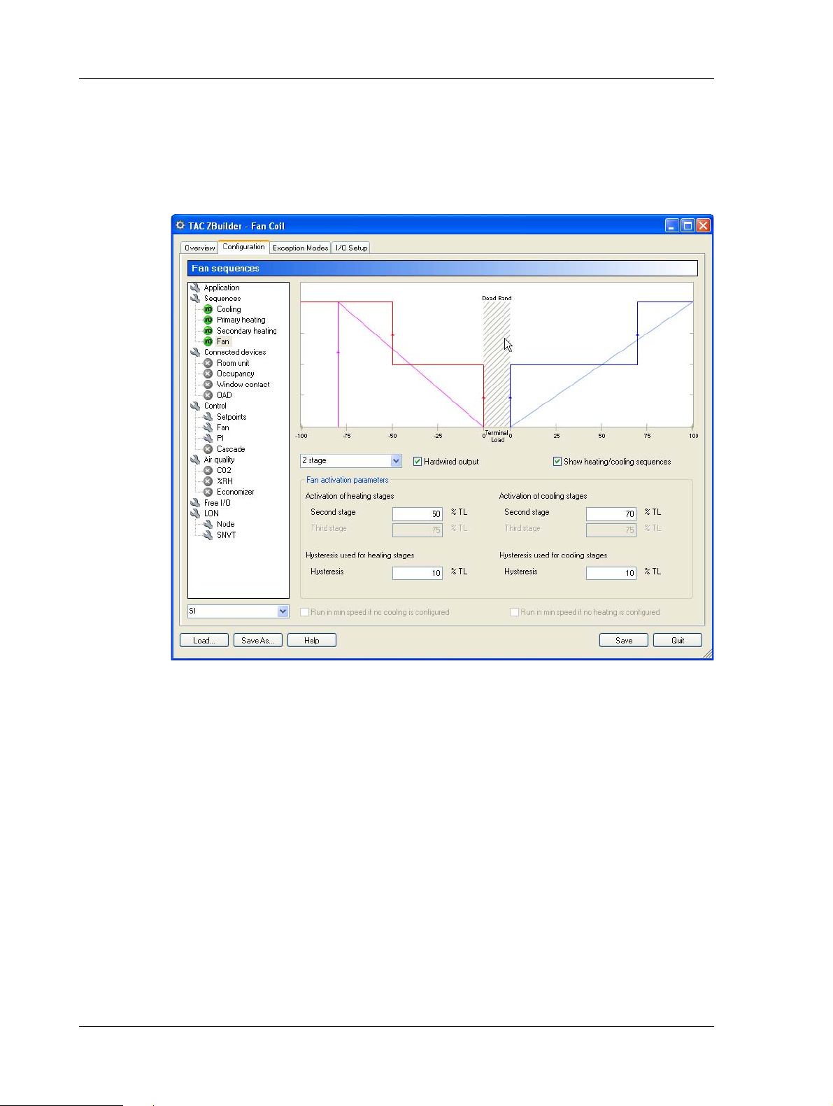
3.4.2 Adjusting the Fan Parameters
In the example, we use the template’s 2-stage fan, but adjust the on/off
delay times and the deadband.
To adjust the Fan parameters
1 In the tree structure, select Sequences\Fan.
2 In the fan type list, select the required fan type. In the example,
2 stage.
Schneider Electric Buildings, Dec 2011 29 (126)
04-00035-02-en (EN)
Page 30
3 Creating the TAC Xenta 120 Configuration TAC Xenta, TAC Xenta 120
3 Make sure the Hardwired output checkbox is selected.
4 In the Activation of cooling stages, Second stage box, enter the
required value. In the example, “70”.
5 Select the Show heating/cooling sequence checkbox, to superim-
pose the heating/cooling sequence on the fan sequence.
3.4.3 Adding a Room Unit
Several types of room temperature sensor units can be connected to the
TAC Xenta 120 controller series.
In the example, we want to add the STR 106 to the controller.
To add a Room unit
1 In the tree structure, select Connected devices/Room unit.
30 (126) Schneider Electric Buildings, Dec 2011
04-00035-02-en (EN)
Page 31

TAC Xenta, TAC Xenta 120 3 Creating the TAC Xenta 120 Configuration
2 In the Select hardwired room unit area, click the required room
unit. In the example, STR 106 to include that room unit.
3.4.4 Adding an Occupancy Signal
In order to let the controller change between occupancy modes, an occupancy signal must be activated.
In the example, we specify an occupancy signal via a SNVT.
To add an Occupancy Signal
1 In the tree structure, select Connected devices\Occupancy.
2 Select the Active checkbox.
3 Make sure the Hardwired occupancy sensor checkbox is cleared ,
which means the SNVT will be used.
Schneider Electric Buildings, Dec 2011 31 (126)
04-00035-02-en (EN)
Page 32

3 Creating the TAC Xenta 120 Configuration TAC Xenta, TAC Xenta 120
Note that the Occupancy icon in the tree to the left has been
changed to a yellow ‘SNVT’ icon.
3.4.5 Adding a Window Contact
In order to define an Exception Mode, the corresponding hardware
device must be activated.
In the example, we specify a hardwired window contact.
To add a window contact
1 In the tree structure, select Connected devices\Window contact.
2 Select the Active checkbox.
32 (126) Schneider Electric Buildings, Dec 2011
04-00035-02-en (EN)
Page 33

TAC Xenta, TAC Xenta 120 3 Creating the TAC Xenta 120 Configuration
3 Select the Hardwired window contact checkbox.
3.4.6 Adjusting the Control Parameters for the Fan
To protect the reheater, it is common to let the fan run some time after
the reheater has been turned off.
In the example, we increase the Off delay time.
To adjust the control parameters for the fan
1 In the tree structure, select Control\Fan.
2 Click the Heating delays text to display the parameters.
Tip
Y ou can also click the + -icon next to the text to display the parameters.
3 In the Off delay heating mode box, enter the required value. In
the example, “30”.
4 Click the Run in deadband text to display the parameters.
Schneider Electric Buildings, Dec 2011 33 (126)
04-00035-02-en (EN)
Page 34

3 Creating the TAC Xenta 120 Configuration TAC Xenta, TAC Xenta 120
5 Select the Run in deadband when in occupied mode checkbox.
3.5 Specifying an Exception Mode
Exception Modes are used to describe a number of events which in
some way may interfere with normal control.
In the example, we want to turn off all heating/cooling if the window
has been left open for more than two minutes. We describe this case in
an Exception Mode.
To specify an Exception mode
1 Click the Exception Modes tab.
2 Click the Exception Mode 1 text to display the parameters.
3 In the left Activation input list, select the required input. In the
example, Window contact.
4 In the right Activation input list, select the required condition. In
the example, Input is inactive.
5 In the Delays area, in the Delay on box, enter the required value.
In the example, “120”.
34 (126) Schneider Electric Buildings, Dec 2011
04-00035-02-en (EN)
Page 35

TAC Xenta, TAC Xenta 120 3 Creating the TAC Xenta 120 Configuration
6 In the Exception mode description area, enter a descriptive text.
In the example, “Window contact”.
Note
The information text can display max. 110 characters.
7 Click the Exception Mode 1 text to hide the parameters.
The information text is now displayed as a label for this exception.
3.6 Changing the Inputs/Outputs configuration
When hardwired inputs and outputs are used in the application,
ZBuilder automatically selects suitable I/O terminals on the controller.
Schneider Electric Buildings, Dec 2011 35 (126)
04-00035-02-en (EN)
Page 36

3 Creating the TAC Xenta 120 Configuration TAC Xenta, TAC Xenta 120
However, the inputs and outputs can be manually changed to other suitable ports, if that is required.
ZBuilder also lists SNVTs for functions that you have enabled, but chosen not to use hardwired I/O for. These SNVTs need to be bound.
In the example, we choose relay contact K4 for our Secondary heating.
To change the Inputs/Outputs configuration
1 Click the I/O Setup tab.
2 In the IO ports area, in the Output list, click the suggested output
port. In the example, K1, Sec. Heating 1 - 1st stage.
3 Point at K1 and drag the output to the required port. In the exam-
ple to K4.
In the Functions bound to SNVTs list, used SNVTs are displayed as a
reminder that they need to be bound.
In the example, the SNVT nviOccSensor is displayed since the occupancy sensor is not hardwired but is signalled via a SNVT.
36 (126) Schneider Electric Buildings, Dec 2011
04-00035-02-en (EN)
Page 37

TAC Xenta, TAC Xenta 120 3 Creating the TAC Xenta 120 Configuration
3.7 Documenting and Saving the Configuration
The configuration process is now complete. Only documenting and saving the result remains. The saved file is later used for download of the
configuration into the controller.
In the example, this is done in Chapter 4, “Installing TAC Xenta 120 in
a Classic Network”, on page 39.
3.7.1 Documenting the Configuration on a Printout
For archiving purposes, the I/O Setup and some other details of the configuration can be easily printed in a standardized form.
To learn more about how to document the configuration, see
Chapter 5.5, “Documenting the Configuration”, on page 53.
In the example, we add some lines of description and make a standard
printout.
To print out the Configuration
1 Click the Overview tab. In the Selected devices area an overview
of the application is shown.
2 In the Description box, enter a descriptive text. In the example,
“4-pipe fan-coil application for the lab in the Engineering area”.
Schneider Electric Buildings, Dec 2011 37 (126)
04-00035-02-en (EN)
Page 38

3 Creating the TAC Xenta 120 Configuration TAC Xenta, TAC Xenta 120
3 Click Print preview.
A Print preview window opens, showing the configuration name,
date and time, the descriptive comment, the I/O connections, and a
list of the used user configuration parameters (UCPTs).
4 Click the Print button in the tool bar to get a printout on the default
printer.
5 Click Close.
3.7.2 Saving the Configuration File
The current configuration may be saved either as an ordinary configuration file (*.zbc), or as a configuration template (*.zbt), but in the latter
case only by using the Save as button.
To learn more about how to save the configuration file, see
Chapter 5.5.3, “Saving the Configuration”, on page 55.
In the example, we will save the application as an ordinary configuration file.
To save the configuration file
1 Click the Overview tab, click Save.
2 Browse to the folder where the file will be saved. In the example,
C:\ProjectACME\DeviceDescr .
3 Enter the configuration file name. In the example, Engr_Lab.zbc.
4 Click Quit to quit ZBuilder.
38 (126) Schneider Electric Buildings, Dec 2011
04-00035-02-en (EN)
Page 39

TAC Xenta, TAC Xenta 120 4 Installing TAC Xenta 120 in a Classic Network
4 Installing TAC Xenta 120 in a Classic
Network
The Xenta 120 has to be added to the LonWorks network to be able to
download the parameters from the configuration file to the TAC Xenta
120 using ZBuilder. The Xenta 120 can be added at the same time as the
other devices on the LonWorks network, or it can be added later to an
existing network.
For more information on how to create LonWorks networks, see the
Engineering Classic Networks and/or Engineering LNS Networks.
Before downloading the parameters, you load an already created configuration into ZBuilder. At this stage you can make changes to the configuration file and save them to the configuration file if required.
The configuration file is then transferred to the Vista database and from
there downloaded to the Xenta 120.
2a. Load
Config files
(2b. Save as)
ZBuilder
Fig. 4.1: Using ZBuilder as a plug-in for TAC Vista
1. Edit
TAC Xenta 120
3. OK or Apply
Engineering
(and Operating)
TAC Vista
Vista db
Operating
(online)
In the example, we will add one TAC Xenta 120 to an existing Classic
network.
4.1 Adding and Configuring the TAC Xenta 120
You can add and configure Xenta 120 devices in Vista without be ing
connected to the devices.
From the Vista point of view, TAC Xenta 120 is like a LonWorks
device with configuration parameters that can be edited.
TAC Xenta 121
with basic
application sw
4.1.1 Adding a LonWorks Group
The Xenta 120 is added to a LonWorks group in the LonWorks network.
Schneider Electric Buildings, Dec 2011 39 (126)
04-00035-02-en (EN)
Page 40

4 Installing TAC Xenta 120 in a Classic Network TAC Xenta, TAC Xenta 120
In the example, we add the LonWorks group, 2nd_Floor_LW to the
LonWorks network, ACME_Inc.
To add a LonWorks group
1 In Vista workstation, change the Vista mode to Engineering.
2 In the Folders pane, right-click the LonWorks network object that
the LonWorks group belongs to. In the example, VistaSRV1ACME_Inc.
3 Point to New, point to Device, and then click LonWorks Group.
4 Name the LonWorks group. In the example, 2nd_Floor_LW.
4.1.2 Adding a TAC Xenta 120
You need to add the Xenta 120 to a LonWorks gro up on the LonWork s
network.
In the example, we name the Xenta 120 “Engr_Lab” and add it to the
LonWorks group 2nd_Floor_LW on the ACME_Inc Lonworks network.
To add a TAC Xenta 120
1 In Vista Workstation, in the Folders pane, right-click the Lon-
Works group the Xenta 120 belongs to. In the example,
VistaSRV1-ACME_Inc-2nd_Floor_LW.
2 Point to New, point to Device, and then click on TAC Xenta 120.
3 Click Next.
40 (126) Schneider Electric Buildings, Dec 2011
04-00035-02-en (EN)
Page 41

TAC Xenta, TAC Xenta 120 4 Installing TAC Xenta 120 in a Classic Network
4 In the Name box, enter a name for the Xenta 120. In the example,
Engr_Lab.
5 Click Next.
6 In the Neuron ID box, enter the neuron ID of the Xenta 120.
7 In the File system box, browse to the Xenta 120 external interface
file (.xif). In the example,
C:\ProjectACME\DeviceDescr\X120FCw1.xif.
Notes
• The external interface files used together with Xenta 120 are
delivered with V ista. If Vista is installed in the default folder, the
files are found in the C:\Program Files\TAC\TAC Vista [version]\$ini folder.
• For a Xenta 121-HP (Heat Pump), the external interface file
X120HPw1.xif is used.
Schneider Electric Buildings, Dec 2011 41 (126)
04-00035-02-en (EN)
Page 42

4 Installing TAC Xenta 120 in a Classic Network TAC Xenta, TAC Xenta 120
8 Click Finish.
9 Click Close.
The TAC Xenta 120 device has now been added to the network .
4.1.3 Configuring a TAC Xenta 120
We need to start ZBuilder from TAC Vista and load a configuration file
in order to transfer the parameters from the configuration file to the
Vista database.
In the example, we load the configuration file, Engr_Lab.zbc, created in
the previous chapter.
To configure a TAC Xenta 120
1 In TAC Vista, right-click the new Xenta 120 device. In the exam-
ple, VistaSRV-2nd_Floor_LW-Engr _Lab.
2 Click Edit.
TAC ZBuilder starts.
3 In ZBuilder click Load.
4 In the Select File dialog box, click Browse for Configuration or
Template File.
42 (126) Schneider Electric Buildings, Dec 2011
04-00035-02-en (EN)
Page 43

TAC Xenta, TAC Xenta 120 4 Installing TAC Xenta 120 in a Classic Network
5 In the Browse for Configuration or Template File, browse to the
configuration file. In the example,
C:\ProjectAcme\DeviceDescr\Engr_Lab.zbc.
6 Click OK.
Schneider Electric Buildings, Dec 2011 43 (126)
04-00035-02-en (EN)
Page 44

4 Installing TAC Xenta 120 in a Classic Network TAC Xenta, TAC Xenta 120
7 Click OK.
Note
The contents of the configuration file have now been loaded into
ZBuilder. Last minute changes may be done in ZBuilder and if so,
you may want to Save as these changes to the existing configuration file, or to a new configuration file.
8 Click OK to transfer the configuration parameters to the Vista
database and close ZBuilder.
Tip
You can click Apply to transfer the configuration parameters to the
Vista database without closing ZBuilder.
44 (126) Schneider Electric Buildings, Dec 2011
04-00035-02-en (EN)
Page 45

TAC Xenta, TAC Xenta 120 4 Installing TAC Xenta 120 in a Classic Network
Note
When editing the configuration file for a Xenta 120 that is already
installed on the LonWorks network and Vista is in Operating mode,
the configuration download to the Xenta 120 will have already
occurred at the ZBuilder Apply/OK command and no download and
commission is needed.
A reset of the neuron of the Xenta 120 is performed by Vista after a
configuration change to make the changes valid. If the reset fails, you
have to perform a manual restart. For more information on how to
reset a neuron, see Section 6.1.2, “Resetting a Neuron”, on page 58.
4.2 Commissioning and Downloading
The configuration parameters have to be downloaded from the Vista
database to the TAC Xenta 120. To be able to do a commission and
download, you have to be connected to the LonWorks network.
To Commission and Download
1 In Vista Workstation, in the folders pane, right-click the Xenta
120. In the example, VistaSRV1-2nd_Floor-Engr_Lab.
2 Click Commission and Download.
3 Click Download parameters from Vista to device.
4 Click OK.
Schneider Electric Buildings, Dec 2011 45 (126)
04-00035-02-en (EN)
Page 46

4 Installing TAC Xenta 120 in a Classic Network TAC Xenta, TAC Xenta 120
5 In the TAC Vista Load – Upload Parameters dialog, click .
6 Click Continue.
7 Click Close.
8 Change the Vista mode to Operating.
9 In the folders pane, refresh the tree structure and check that the
Xenta 120 is online.
Important
A reset of the neuron of the Xenta 120 is performed by Vista after a
configuration change to make the changes valid. If the reset fails, you
have to perform a manual restart. For more information on how to
reset a neuron, see Section 6.1.2, “Resetting a Neuron”, on page 58
46 (126) Schneider Electric Buildings, Dec 2011
04-00035-02-en (EN)
Page 47

REFERENCE
5 ZBuilder - the Configuration Tool
6 TAC ZBuilder as a Plug-in
7 Application Types (Configuration)
8 Fan Control
9 Connected Devices and Network
Parameters
10 Control Issues
11 Exception Modes
12 I/O Setup
Page 48

Page 49

TAC Xenta, TAC Xenta 120 5 ZBuilder - the Configuration Tool
Fan-Coil
or
Heat pump
Room temperature
Offset temp. dial
Bypass button
Occupancy sensor
CO
2
sensor
%RH sensor
Outdoor
temp.
sensor
Duct temp.
sensor
Water temp.
sensor
Outside Air
Damper
Electrical
Heater
Door/
Window
contact
Glass break
sensor
TAC Xenta 120
5 ZBuilder - the Configuration Tool
5.1 Usage
The TAC Xenta 120 series controllers are used for applications that can
be designed and configured in a very flexible way, using ZBuilder.
The tool is a software package that can be run stand-alone or as a device
plug-in to TAC Vista® or L
ONMAKER®.
Fig. 5.1: A TAC Xenta 120 series controller and examples of peripherals
The configuration created by this tool is transferred to LNS or Vista and
is loaded into a TAC Xenta® 120 controller, which has the required set
of Inputs and Outputs and the basic software for the relevant applica-
5.2 ZBuilder Overview
tion.
The purpose of the ZBuilder is to create a software configuration file,
where hardware and/or SNVT input signals are used to affect a specific
Climate Control Device (CCD), resulting in signals directed to hardware and/or SNVT outputs.
Schneider Electric Buildings, Dec 2011 49 (126)
04-00035-02-en (EN)
The contents of the configuration file are used by TAC Vista or L
M
AKER to download the configuration in a Xenta 120 unit, which
ON-
Page 50

5 ZBuilder - the Configuration Tool TAC Xenta, TAC Xenta 120
Template
(*.zbt)
Config
parameters
Config file
(*.zbc)
TAC Vista/
LNS
Modified
config file
ZBuilder
TAC Xenta 121
with basic
application sw
already contains the required software for the intended application (for
example Fan-Coil or Heat Pump).
.
Fig. 5.2: Creating and downloading a modified configuration file for a
TAC Xenta 121 application.
ZBuilder has a start page, where the user can start with a template
(*.zbt) or edit a previously saved configuration file (*.zbc).
The configuration is then customized in three tabbed pages:
• Configuration
• Exception Modes
• I/O Setup
The Configuration page lists the available Configuration Modules and
the corresponding parameters.
In the Exception Modes page, up to eight exceptions can be defined, that
is, special action at certain events, for example the desired action when
a window is opened.
The I/O Setup page shows how the inputs and outputs for the selected
Xenta 120 hardware are used. This can also be reconfigured here.
A fourth page, Overview is a graphic presentation of the application,
with a list of the most important parameters and a print function for documentation purposes.
The result is saved as a customized Configuration file.
TAC Vista or LonMaker is used to download the configuration file in
the TAC Xenta 120.
TAC Xenta OP can be used to inspect nvi and nvo values. Due to the
many configuration possibilities, the OP cannot be used to configure the
controller.
50 (126) Schneider Electric Buildings, Dec 2011
04-00035-02-en (EN)
Page 51

TAC Xenta, TAC Xenta 120 5 ZBuilder - the Configuration Tool
About TAC ZBuilder
The current version of TAC ZBuilder is found in the About TAC
ZBuilder window, which appears if you click on the icon in the upper
left corner.
Fig. 5.3: Finding version information of TAC ZBuilder
Terminal Load
In the Xenta the control program calculates the Terminal Load, a value
in the range –100% to +100%. This value indicates the amount of heating or cooling power required at the moment.
A negative Terminal Load means that heating is required.
A positive Terminal Load means that cooling is required.
The configuration procedure tells the controller how the CCD (Climate
Control Device) should act at different levels of Terminal Load.
This is shown in a sequence diagram, with the Terminal Load on the X-
axis and the output signals to the CCD on the Y-axis.
In ZBuilder a CCD can consist of up to three heating or cooling devices:
• Primary heating
• Secondary heating
• Cooling
Schneider Electric Buildings, Dec 2011 51 (126)
04-00035-02-en (EN)
Page 52

5 ZBuilder - the Configuration Tool TAC Xenta, TAC Xenta 120
Item tree
Units selection:
SI (metric) or
US (inch-pound)
5.3 Templates and Applications
5.3.1 Selecting a File
At start-up, a template (*.zbt) from a list or a configuration file (*.zbc;
or another template) is selected:
The modified result can then be saved as a new template or file.
There are two basic templates: Fan-Coil and Heat pump.
Once an application type (F-C or HP) has been selected, it is not possi-
ble to Load another type.
If you need another type, you will first have to Save the current type or
restart the tool.
5.4 The Configuration Window
In the left part of the Configuration window, there are an item tree and
a drop-down Units selection menu.
52 (126) Schneider Electric Buildings, Dec 2011
04-00035-02-en (EN)
Page 53

TAC Xenta, TAC Xenta 120 5 ZBuilder - the Configuration Tool
By clicking on a menu in the list, you will be able to inspect and modify
different parameters of the application.
The icons in the tree indicate what kind of parameters are displayed and
some of the properties for the configured devices.
Table 5.1: Icons in Menu tree
Icon Meaning
‘Main’ window, or
Window with additional functions and settings
Window for a configured device that has a hardwired
connection
Window for a configured device that is connected via a
SNVT
Window for a non-used device
5.5 Documenting the Configuration
For documentation and future use, the configuration can be:
• exported as a text file
• printed as a parameter list in a pre-defined format
• associated with a graphical description
• saved as a configuration or a template file
5.5.1 Printing the Configuration Parameters
For documenting and future use, the I/O Setup and other parameter
details of the configuration can be easily printed.
To print the Configuration parameters
1 Click the Overview tab.
2 In the Description field, enter a suitable text.
3 Click Content to select which parts to include with the printout
(or text file export).
4 Click Print preview.
A Print preview window will open, showing the following
(depending on the Content selection):
• Header (application type, configuration file name, and date
and time of preview)
• Description: the text from the Description field.
• Connections: the IO Ports from the I/O Setup.
Schneider Electric Buildings, Dec 2011 53 (126)
04-00035-02-en (EN)
Page 54

5 ZBuilder - the Configuration Tool TAC Xenta, TAC Xenta 120
• SNVTs expected to be bound: the list of SNVTs from the I/O
Setup.
• Exception Mode descriptions: for each defined Exception
Mode the Information text is presented.
• Configuration parameters: a list of the used UCPTs (user configuration parameters), their Name, Position (order in table),
Index (bit no., 0 is most significant), and Value.
5.5.2 Associating a Graphic with the Configuration
To give a quick visual cue, a graphic can be shown in the Description
area of the Select File window. Below the picture, the descriptive text
from the Overview Description field also appears.
Fig. 5.4: Graphic and text description of selected Configuration file
Any .jpg-file with the same name and residing in the same folder will
appear in the window.
Example: If the configuration file resides as
C:\Program Files\TAC\TAC ZBuilder\Templates\HeatPump2.zbc
then the graphic
C:\Program Files\TAC\TAC ZBuilder\Templates\HeatPump2.jpg
will appear in the square Description window.
The resolution of the .jpg file should not exceed 120x120 pixels.
Note
In the Overview window there is a graphical view of the Selected
devices. This is a dynamically drawn graphic, updated with any
change in the configuration. This graphic cannot be saved separately
at this stage.
54 (126) Schneider Electric Buildings, Dec 2011
04-00035-02-en (EN)
Page 55

TAC Xenta, TAC Xenta 120 5 ZBuilder - the Configuration Tool
5.5.3 Saving the Configuration
The current configuration can be saved
• as an ordinary configuration file (*.zbc), or
• as a configuration template (*.zbt),
but in the latter case only by using the Save as button.
Zbuilder is always started with a configuration selected by the user. As
soon as a change has been made, the Save button is made available.
Clicking on Save will immediately overwrite the selected configuration
(unless a template has been used).
In order to preserve the original configuration, use the Save as button,
as this will ask for a file name, folder, and format (.zbc or .zbt). After
this, Save can be used.
Before making the final Save or Save as, you may consider these
points:
•In Overview, enter a descriptive text in the Description field. This
text will appear in the Configuration Parameters printout and the
Select File window described above.
• Associate a descriptive graphic with the same name as the configuration file, as shown above.
• Decide if the current configuration shall be used as a template or
an ordinary file.
Schneider Electric Buildings, Dec 2011 55 (126)
04-00035-02-en (EN)
Page 56

5 ZBuilder - the Configuration Tool TAC Xenta, TAC Xenta 120
56 (126) Schneider Electric Buildings, Dec 2011
04-00035-02-en (EN)
Page 57

TAC Xenta, TAC Xenta 120 6 TAC ZBuilder as a Plug-in
6 TAC ZBuilder as a Plug-in
TAC Xenta 120 can be treated as a LONWORKS device with configuration parameters that can be edited, using ZBuilder as a plug-in to
TAC Vista or L
6.1 As a Plug-in in TAC Vista
ZBuilder is used as a Plug-in in Vista when Xenta 120 devices are
installed on a classic network.
6.1.1 Starting ZBuilder from TAC Vista
As described in Chapter 4, “Installing TAC Xenta 120 in a Classic Network”, on page 39, we start ZBuilder from TAC Vista in order to transfer the parameters from the existing configuration file to the Vista
database.
ONMAKER.
To start ZBuilder from TAC Vista
1 In TAC Vista, right-click the new Xenta 120 device and select
Edit.
Fig. 6.1: Starting ZBuilder with an Edit command
TAC ZBuilder should now start.
2 In the ZBuilder Select File window, click Browse for Configura-
tion or Template File and select the configuration file from the
previous chapter, Engr_Lab.zbc.
The contents of the configuration file are now loaded into ZBuilder.
Last minute changes may be done in ZBuilder and, if so, you may
want to Save as these changes to the existing configuration file or
to a new configuration file.
Schneider Electric Buildings, Dec 2011 57 (126)
04-00035-02-en (EN)
Page 58

6 TAC ZBuilder as a Plug-in TAC Xenta, TAC Xenta 120
6.1.2 Resetting a Neuron
A reset of the neuron of the Xenta 120 is performed by Vista after a configuration change to make the changes valid. If the reset fails, you must
perform a manual reset.
To reset the neuron
1 In Vista Workstation, in the folders pane, right-click the Xenta 120
device.
2 Point to Advanced Operations and then click Reset Neuron.
3 Click Yes.
6.2 As a Plug-in in LonMaker
ZBuilder is used as a Plug-in in LonMaker when Xenta 120 devices are
installed on an LNS network.
6.2.1 Starting ZBuilder from LonMaker
ZBuilder is started from LONMAKER in order to transfer the parameters
from the existing configuration file to the LNS database.
Important
Do not use the LonMaker Browser to inspect or change the nci, scpt,
or ucpt values. These values can be interpreted in different ways and
only ZBuilder has the logic to interpret the Xenta 120 applications.
To start ZBuilder from LonMaker
1 In LonMaker, in the drawing, right-click the Xenta 120 device.
58 (126) Schneider Electric Buildings, Dec 2011
04-00035-02-en (EN)
Page 59

TAC Xenta, TAC Xenta 120 6 TAC ZBuilder as a Plug-in
2 Click Configure.
Fig. 6.2: Starting ZBuilder from LonMaker with a Configure command
TAC ZBuilder should now start.
Tips
• Y o u can also click System Plug-Ins on the LonMaker menu and
start TAC ZBuilder from the Plug-Ins window
• If ZBuilder does not start (LonMaker Browser starts instead),
you must register ZBuilder as a plug-in. For more information on
how to register a plug-in, see Section 6.2.4, “Registering
ZBuilder as a Plug-in”, on page 61.
6.2.2 Configuring a TAC Xenta 120
Configuration of the Xenta 120 in ZBuilder transfers the parameters to
the LNS database. If the device is commissioned at the time, the parameters will also be downloaded to the Xenta 120; otherwise, the parameters will be downloaded when the Xenta 120 is commissioned.
For information on how to commission a device, see the Engineering
LNS Networks manual.
To configure a TAC Xenta 120
1 In ZBuilder, in the Select File dialog box, click Browse for Con-
figuration or Template File.
2 Select the required template or browse to the required configura-
tion file.
Schneider Electric Buildings, Dec 2011 59 (126)
04-00035-02-en (EN)
Page 60

6 TAC ZBuilder as a Plug-in TAC Xenta, TAC Xenta 120
The contents of the template/configuration file are now loaded into
ZBuilder. Last minute changes may be done in ZBuilder and, if so,
you may want to Save as these changes to the existing configura-
tion file or to a new configuration file.
3 Edit the configuration parameters as required.
4 Click Save as.
5 Browse to a suitable folder.
6 Click Save.
7 Click OK to transfer the parameters to the LNS database and close
ZBuilder.
If several Xenta 120 devices are to have the same configuration, there
is a great advantage in updating the LonMaker device shape with the
complete configuration. For more information on how to Update a LonMaker device shape, see Section 6.2.3, “Updating a LonMaker Device
Shape”, on page 60.
Tip
You can click Apply to transfer the configuration parameters to the
LNS database without closing ZBuilder.
Note
When editing the configuration file for a Xenta 120 that is installed on
the LonWorks network and commissioned, the configuration download to the Xenta 120 will occur at the ZBuilder Apply/OK command.
A reset of the neuron of the Xenta 120 is performed by LonMaker after
a configuration change to make the changes valid. If the reset fails, you
must perform a manual restart. For more information on how to reset
a neuron, see Section 6.2.5, “Resetting a Neuron”, on page 62.
6.2.3 Updating a LonMaker Device Shape
If several Xenta 120 controllers are to use the same configuration, you
should use the complete, updated LonMaker Xenta 120 device template
to simplify the download procedure.
To use the LonMaker template for Configuration Download
1 Start ZBuilder from the configured device in LonMaker.
2 Click the Configuration tab.
3 In the tree structure, select LON.
4 Click Update Template.
60 (126) Schneider Electric Buildings, Dec 2011
04-00035-02-en (EN)
Page 61

TAC Xenta, TAC Xenta 120 6 TAC ZBuilder as a Plug-in
The LonMaker Xenta 120 device template is now updated with the
complete configuration, including the extension records (the specified STR, the Exception Modes texts, and so on).
5 In LonMaker, drag the required number of Xenta 120 shapes to the
drawing. Select Default values as Configuration property source.
The correct parameters will be associated with the new Xenta 120
devices.
6 Commission each Xenta 120 device.
7 Perform a node reset, see Section 6.2.5, “Resetting a Neuron”, on
page 62.
Important
When this configuration method is used, the last step is mandatory to
complete the commissioning procedure.
Note
In order to streamline the work with multiple devices, the Xenta 120
shapes do not contain any Functional Blocks with nvi:s/nvo:s
included. The reason is that the Update Template button does not
update the nci:s connected to that/those FBs that exist in the shape.
To create your own shape containing FBs, make sure the device is configured in ZBuilder and that the LNS database is updated (Update
Template), before the shape is created. An SCC FanCoil FB, containing the required variables for binding, can easily be created using the
LonMaker basic Shapes.
6.2.4 Registering ZBuilder as a Plug-in
Normally, TAC ZBuilder is registered together with all other plug-ins
when the network drawing is created. However, it may be necessary to
repeat the registration.
To register ZBuilder as a Plug-in
1 In LonMaker, on the LonMaker menu, click Network Pr operties
2 Click the Plug-in Registry tab.
3 In Already Registered list, select TAC ZBuilder (Version x.x.x).
Schneider Electric Buildings, Dec 2011 61 (126)
04-00035-02-en (EN)
Page 62

6 TAC ZBuilder as a Plug-in TAC Xenta, TAC Xenta 120
4 Click Add.
5 Click OK.
6 Wait until the ZBuilder is registered.
6.2.5 Resetting a Neuron
A reset of the neuron of the Xenta 120 is performed by LonMaker after
a configuration change to make the changes valid. If the reset fails, you
will need to perform a manual reset.
To reset a neuron
1 In LonMaker, in the drawing, right-click the Xenta 120 device.
2 Click Manage.
3 Click Reset.
4 Quit the LonMaker Device Manager dialog box.
62 (126) Schneider Electric Buildings, Dec 2011
04-00035-02-en (EN)
Page 63

TAC Xenta, TAC Xenta 120 7 Application Types (Configuration)
-100 -83 -50 0
0 33 100
Output
signal
Terminal
Load
Cooling
Fan
Primary
Secondary
heating
7 Application Types (Configuration)
7.1 Terminal Load and the Heating/Cooling Sequence
The function of the TAC Xenta 120 is determined by the Terminal
Load, that is, how much of the heating/cooling power is needed at each
point in time.
It is possible to configure up to two heating devices and one cooling
device. Each of these can be a multistage, pwm, analog, or increase/
decrease device.
The user defines the sequence in relation to the Terminal Load, and the
resulting process is displayed in a diagram with the Terminal Load on
the x-axis and the output signal on the y-axis.
An example of a Heating/Cooling sequence is shown below.
Fig. 7.1: The Heating/Cooling sequence as a function of the Terminal
Load
Schneider Electric Buildings, Dec 2011 63 (126)
04-00035-02-en (EN)
Page 64

7 Application Types (Configuration) TAC Xenta, TAC Xenta 120
Window contact
Heating
coil
1-, 2- or
3-speed Fan
Wall module
Occupancy
sensor
Discharge air
sensor
Incr./decr. or
thermal actuators
Reheating
stage
Economizer Cooling
coil
Humidity
sensor
Outside temp.
sensor
Window contact
Heating/cooling
coil
1-, 2- or
3-speed Fan
Wall module
Occupancy
sensor
Discharge air
sensor
Incr./decr. or
thermal actuator
Water temp.
sensor
Reheating
stage
Economizer
CO2 sensor
Outside temp.
sensor
7.2 The 4-pipe Fan-Coil
An example of a 4-pipe Fan-Coil system:
Fig. 7.2: 4-pipe Fan-Coil
7.3 The 2-pipe Fan-Coil
An example of a 2-pipe Fan-Coil system:
Fig. 7.3: 2-pipe Fan-Coil
Change-over Temperature
In a 2-pipe Fan-Coil unit there is a water temperature sensor for the
incoming flow. When the controller is in Auto mode it will change
between heating and cooling, based on a configurable change-over tem-
64 (126) Schneider Electric Buildings, Dec 2011
perature level.
There is a heating/cooling change-over hysteresis. With the change-
over temperature at 20 °C (68 °F) and change-over hysteresis of 3 °C
(5.4 °F), the fan-coil, coming from heating, will change to cooling at
04-00035-02-en (EN)
Page 65

TAC Xenta, TAC Xenta 120 7 Application Types (Configuration)
2726252423222120191817161514
C
o
13
heating start
change-over temp.
cooling start
change-over
hysteresis
(from cooling)
(from heating)
Window contact
Heating/cooling
compressor
1-, 2- or
3-speed Fan
Wall module
Occupancy
sensor
Discharge air
sensor
Isolation
valve
Water temp.
sensor
Reheating
stage
Economizer
CO2 sensor
Outside temp.
sensor
Reversing
valve
21.5 °C (70.7 °F). Coming from cooling it will start heating at 18.5 °C
(65.3 °F).
Fig. 7.4: 2-pipe Fan-Coil changeover temperature parameters
If no water temperature sensor is used, the mode has to be set to HEAT
or COOL by a superior system.
Note
It is possible to allow heating by a secondary heating stage, even if the
mode indicates that the water temperature is too low to allow heating
by the fan-coil itself.
7.4 The Heat Pump
An example of a Heat Pump system.
Fig. 7.5: Heat Pump with isolation and reversing valves
Isolation valve
Schneider Electric Buildings, Dec 2011 65 (126)
04-00035-02-en (EN)
In water-sourced heat pumps, the surrounding water flow can be shut
off for energy saving purpose. This is done via an isolation valve connected to a digital output.
Page 66

7 Application Types (Configuration) TAC Xenta, TAC Xenta 120
The isolation valve will open when the application calls for the compressor, but the compressor itself is not activated until the configured
delay time has expired.
Reversing valve
A reversing valve is used to set a heat pump in heating or cooling mode.
The valve is controlled by a digital output and there are configurable
restrictions on how the valve is operated in relation to the compressor
operation.
The position is defined by the heating/cooling mode. A delay can be set
defining the time from when the reversing valve is switched until the
compressor may start.
Note
It is possible to allow heating by a secondary heating stage, even if the
mode indicates that the heat pump output is too low to allow heating
by itself.
7.5 Different Control Signals
The following control signals are available:
•On/off
• Multistage: 2 stage, 3 stage
• Increase/decrease
• Pulse Width Modulation (PWM)
•Analog
Note
Normally, the heating and cooling sequences and their control signals
are totally independent of each other. However, because the same
valves and actuators are used, the following two application types use
the same control signals for Primary Heating and Cooling:
• 2-pipe Fan-Coil
• Heat Pump with Reversing valve
66 (126) Schneider Electric Buildings, Dec 2011
04-00035-02-en (EN)
Page 67

TAC Xenta, TAC Xenta 120 7 Application Types (Configuration)
On/off
Fig. 7.6: An example of an On/off heating sequence
1 Activates device at this Terminal Load, normally 0.
2 Hysteresis value. For the output to go back to off, the Terminal
Load has to decrease to –(20% – 15%) = –5% in this example.
3 Minimum time the output will be on when it is activated.
4 Select which type of device is connected. For a normally closed
device, the output will be off when the device is set to off.
A summary is shown in the table below.
Table 7.1: Output to control different types of devices
Output
Device off Device on
Normally closed off on
Normally open on off
Schneider Electric Buildings, Dec 2011 67 (126)
04-00035-02-en (EN)
Page 68

7 Application Types (Configuration) TAC Xenta, TAC Xenta 120
Multistage
Fig. 7.7: An example of a 3 stage cooling sequence
1 Activates device at this Terminal Load
2 Activates second stage at this load
3 Device fully active at this load
4 Hysteresis value, same for all stages. Note, however, that the
resulting control signal cannot reach into the Dead Band.
5 Minimum time in seconds for ON time in each stage. (The stage
cannot be passed too quickly.)
6 Minimum time in seconds for OFF time in each stage.
7 Lower stages should keep work ing when higher stages are started.
Valid for Multistage applications.
8 Cycle stages (1 => 2 => 3 etc.). If no stage is active, at the next
activation the controller will select the next stage.
The purpose of this function is to achieve a more distributed usage
of the different stages.
68 (126) Schneider Electric Buildings, Dec 2011
04-00035-02-en (EN)
Page 69

TAC Xenta, TAC Xenta 120 7 Application Types (Configuration)
Incr/decr, PWM (’Duty Cycle’), Analog
Fig. 7.8: An example of an adjusted heating sequence
1 Activates device at this Terminal Load
2 Device fully active at this load
3 Minimum control signal, that is, signal cannot become less.
4 Maximum control signal, that is, signal cannot become greater.
For the Increase/decrease type of control, the actuator stroke time also
has to be specified; from fully closed to fully open.
For the PWM (’Duty Cycle’) type of control, one additional value must
be specified:
•the complete Period (cycle time, the time for one full period)
An output pulse, proportional in length to the control signal, is sent each
period. The ‘duty cycle’ is the ratio between the on-time and the period.
Configurable items:
•Period.
• % of width correlating to 0% control signal (scaling, minimum
duty cycle).
• % of width correlation to 100% control signal (scaling, maximum
duty cycle).
• Delta (if change is less, the value is not repeated for each cycle).
Schneider Electric Buildings, Dec 2011 69 (126)
04-00035-02-en (EN)
Page 70

7 Application Types (Configuration) TAC Xenta, TAC Xenta 120
PWM, US-type
In the US another type of PWM control is sometimes used, applicable
only for actuators giving a position directly proportional to the pulse
width, and not dependant of cyclic updates.
A PWM ‘pulse’ is sent only once, when a change occurs.
In such cases it is beneficial to send an update pulse only when the
width-change is greater than a threshold value, specified in another
parameter:
• Pulse only if change is greater or equal to
7.6 Peripheral Units and Additional Functions
The remaining chapters of the Reference section treat various types of
devices that are normally used with Fan-Coil or Heat Pump applications.
There are also chapters for the Exception Modes and I/O Setup functions of the tool.
The devices and parameters are basically presented in chapters with
headings that follow the ZBuilder tabs and windows.
70 (126) Schneider Electric Buildings, Dec 2011
04-00035-02-en (EN)
Page 71

TAC Xenta, TAC Xenta 120 8 Fan Control
8 Fan Control
8.1 General
The connected fan can be either analog, on/off controlled (1-speed fan
device), or multistage controlled (2 or 3 speeds).
It is also possible to configure in which occupancy modes the fan shall
run. The default setting means the fan will be activated in occupied and
bypass mode, and off in all other occupancy modes, except when there
is a heating or cooling demand.
Important
For devices that can have either hardwired or SNVT input, the SNVT
value, if it is valid, will always take precedence.
This applies even when the Hardwired box is selected!
8.2 Analog Control
With analog control a continuous increase of the fan speed is achieved.
Fig. 8.1: Analog fan control
Schneider Electric Buildings, Dec 2011 71 (126)
04-00035-02-en (EN)
Page 72

8 Fan Control TAC Xenta, TAC Xenta 120
8.3 On/off and Multistage Control
On/off is the same as 1 stage control. In 1 and Multistage control, the
fan speed is increased in steps.
Fig. 8.2: 3 stage fan control
8.4 Fan Hysteresis
The hysteresis value (separate for heating and cooling) applies to all
stages, but can never reach into the Dead Band area.
8.5 Other Fan Parameters
8.5.1 Boost
Boost is used for fans requiring a large torque to start.
The Boost time defines how many seconds the fan will run at maximum
speed, before normal application value is used.
8.5.2 Conditioning
Conditioning means that the fan will always be motioned after a specified interval, if not used before.
The Fan conditioning active time is given in minutes. If the fan always
runs at minimum speed, fan boost will be used.
Inactive time is the maximum interval in hours before the fan is activated, if it has not been used before.
72 (126) Schneider Electric Buildings, Dec 2011
04-00035-02-en (EN)
Page 73

TAC Xenta, TAC Xenta 120 8 Fan Control
8.5.3 Cooling delays
To prolong the fan effect, there are some different delay times.
The On delay time keeps the fan from blowing before the temperature
control device has reached a suitable temperature.
It is not used if the fan is defined to be running in dead band.
There is also an Off delay time between the fan being forced Off (and
interlocked temperature control device is shut down) and the fan actually is shut off.
If set, the Off delay time also applies to normal control, that is, when the
temperature control device goes below the TL deactivation level.
Not applicable, though, if fan is defined to be running in dead band.
8.5.4 Heating delays
Similarly, there are delay times in heating mode.
The On delay time keeps the fan from blowing before the temperature
control device has reached a suitable temperature.
8.5.5 Feedback
It is not used if the fan is defined to be running in dead band.
There is also an Off delay time between the fan being forced Off (and
interlocked temperature control device is shut down) and the fan actually is shut off. Often this is used to cool a secondary electrical heater.
If set, the Off delay time also applies to normal control, that is, when the
temperature control device goes below the TL deactivation level.
Not applicable, though, if fan is defined to be running in dead band.
If a fan feedback signal, either connected to an I/O port or via a SNVT,
is used, it must be activated here.
A Proof time can be defined, that is, a minimum number of seconds,
after a fan start, until the feedback status should be on. (Otherwise, an
alarm should be considered.)
Important
For devices that can have either hardwired or SNVT input, the SNVT
value, if it is valid, will always take precedence.
This applies even when the Hardwired box is selected!
8.5.6 Interlock
Primary/secondary heating or cooling interlocked to fan.
Schneider Electric Buildings, Dec 2011 73 (126)
04-00035-02-en (EN)
Page 74

8 Fan Control TAC Xenta, TAC Xenta 120
If interlocked to fan, the heating/cooling device is automatically shut
down in case of a fan failure.
The interlocked devices will also be shut down at a fan off signal from
the room unit or by a nviFanSpeedCmd command.
8.5.7 Run in deadband
The fan can be set to run in dead band when in Occupied, Standby ,
or Unoccupied mode.
8.6 Fan Control from STR Wall units
The fan may also be controlled using the fan mode switch on the wall
modules:
• STR106 (with five modes: Auto, Off, Speeds 1, 2, and 3),
• STR107 (with three modes: Auto, Off, On), or
• STR150, 350/351 (free choice of selectable modes can be configured).
This function is only available when the zone is in Occupied mode.
74 (126) Schneider Electric Buildings, Dec 2011
04-00035-02-en (EN)
Page 75

TAC Xenta, TAC Xenta 120 9 Connected Devices and Network Parameters
9 Connected Devices and Network
Parameters
Some additional devices can be connected to improve the system performance.
They can be connected to the physical inputs of the controller or be
received as SNVT inputs.
Important
For devices that can have either hardwired or SNVT input, the SNVT
value, if it is valid, will always take precedence.
This applies even when the Hardwired box is selected!
9.1 Room Unit
T A C Xenta 121 can be connected to any of the following temperature sensors.
• Room units STR 100/101/102/103/104/106/107/150
• Any 1.8 kohm TAC sensor
• Room unit STR350/351 over a LonWorks network
• Any other Lon sensor
In case several (max 3) space temperature sensors are used, the control-
ler will average their values.
Lon temperature sensors will all be bound to nviSpaceTemp; the system
will separate them internally.
Lon and physically connected devices can be used in parallel or sepa-
rately; their values will be averaged.
For Lon sensors the Offset is set internally in the sensor device. For
other sensors there is a temperature offset input field.
The resulting offset is a numeric addition between the nviSetpntOffset
value and the room unit setting.
Note
For the space temperature and offset values, both hardwired and
SNVT values are used. This is an exception to the general rule about
SNVTs taking precedence over hardwired values.
Some of the sensors require some extra pieces of information.
Schneider Electric Buildings, Dec 2011 75 (126)
04-00035-02-en (EN)
Page 76

9 Connected Devices and Network Parameters TAC Xenta, TAC Xenta 120
9.1.1 STR Modules: I/O Usage
By default, certain ports of the controller will be assigned to certain
STR functions
Hardwired status LED
In STR101/102/103/104/106/107 the status LED can be hardwired to
the controller and is then allocat ed to an out put (an alog Y1 or, as a second alternative, to a relay output, K).
(In STR150 the status LED is replaced by a ‘Man’ symbol in the LCD
display. Also, in STR150 the uncalibrated temperature values are
shown.)
The LED output can be moved to another port (except for STR150!) in
the I/O Setup window. Note, however, that external power supply will
be necessary (24 VAC or any DC voltage 5–24 V).
9.1.2 STR Modules: Additional functions
Bypass button used as on/off
The Bypass button can be used to toggle between Occupied and Unoccupied, or to switch mode to Occupied/Bypass for a specified time.
Activate STR150 reset offset function
There is a so-called hotel reset function for room unit STR150. When
activated, an ‘old’ offset value is not taken into account when going
from Unoccupied to Occupied until the Offset is changed (probably by
a new hotel guest).
Temperature Offset Wheel Scaling
STR102/104/106/107 have plastic pegs on the rear of the offset wheel
to limit the wheel stroke and thus the possible offset values.
In order to allow a full wheel stroke, but still limit the offset values, the
controller can be configured to scale the full stroke according to the settings of the two input fields.
9.2 Occupancy sensor
If an occupancy sensor is connected, it can decide the mode of the controller. It is possible to define delay times both for switching to occupied
and from occupied. If you walk into a room just to pick something up,
there is no need to switch to occupied (Occupancy sensor on time).
Conversely, if you leave for just a short period of time there is no need
to leave occupied mode (Occupancy sensor off time).
There is also a delay time (Delay before leaving occupancy mode) to
let the Xenta stay in Occupied mode for some minutes after no occupancy has been signalled.
76 (126) Schneider Electric Buildings, Dec 2011
04-00035-02-en (EN)
Page 77

TAC Xenta, TAC Xenta 120 9 Connected Devices and Network Parameters
If no occupancy sensor is connected, the controller assumes that the
room is occupied.
The sensor can be connected either directly to the controller, or via the
network, nviOccSensor. When nviOccSensor has received a valid value,
this is used – whether there is a hardwired sensor or not.
The hardwired sensor value is sent out on the network in nvoOccSensor.
If no sensor is connected, the value OC_NUL is sent out. There is a
definable delay before the operation mode is changed from occupied to
standby in nvoEffectOccup. The change in nvoOccSensor only takes
500 ms in order to make other uses of the occupancy sensor possible
(lighting, alarm, and so on.)
9.3 Window Contact
If a window contact is used to activate an Exception Mode, it has to be
defined as one of the Connected devices.
Select Activate and Hardwired window contact, if applicable.
See also Section 11.6, “Some Exception Mode Examples”, on page 98.
9.4 Air Quality Equipment
The air quality is affected by a number of factors, among them:
•the CO
• the relative humidity, %RH
• outside air via an Economizer
To improve the air quality of the zone, the CO
and fresh outdoor air can be supplied when needed.
An outside air damper can be used to minimize energy consumption by
using outside air to assist in achieving the desired temperature. It can
also be used to maintain the CO
If the temperature of the outside air has a value that enables it to assist
in cooling, the economizer control is activated. A PI controller controls
the outside air damper while the control is in the dead band. When there
is a demand for cooling, the outside air damper is fully opened if the outside air can assist in controlling the space temp. In heating, the outside
air damper is held at minimum position.
The %RH/CO
If the decision to use the outside air damper is taken elsewhere, this is
signaled to the application via either:
level
2
control may restrict the economizer operation.
2
level can be monitored
2
level in the zone.
2
• Outside air enthalpy level. If the enthalpy is higher than the configured
value, no economizer control is allowed.
• On/off. The state of an nvi determines whether control is allowed.
Schneider Electric Buildings, Dec 2011 77 (126)
04-00035-02-en (EN)
Page 78

9 Connected Devices and Network Parameters TAC Xenta, TAC Xenta 120
• In both cases above, a configuration will specify the position (in per-
cent) the damper should go to if control is not allowed. This since the
normal minimum position can have different usage.
In unoccupied mode, the outside air damper is always fully closed.
9.4.1 OAD, Outside Air Damper
If an Outside Air Damper is used, it can be controlled to minimize the
energy consumption by using outside air to assist in achieving the
desired temperature.
It can also be used to keep the CO
limit.
Only a few parameters are required, among them the OAD minimum
and maximum positions, the TL activation level, and the hysteresis
value.
9.4.2 CO2 Control
The OAD function has limits for its max and min positions. However,
when in CO
control mode, it is possible to allow a position lower than
2
the minimum position. The reason is that if the CO
setpoint (the air quality is sufficient), closing the damper even
CO
2
more may help in saving energy.
9.4.3 Dehumidification, %RH
An indoor %RH senor can be connected. This can work in two configurable ways.
1 If no external dehumidification equipment is present, the device
can dehumidify the air itself. When the %RH reaches a certain
level, cooling will be forced according to two configurations:
level in the zone within an acceptable
2
value is below the
2
• Start cooling
• Full cooling
The heating control is not forced, which will lead the P/PI control
to maintain the room temperature. If there is an outside air damper,
it will be controlled towards specified minimum position before
cooling is started.
Cooling
%RH
start
Fig. 9.1: Dehumidification by cooling
78 (126) Schneider Electric Buildings, Dec 2011
full
04-00035-02-en (EN)
Page 79

TAC Xenta, TAC Xenta 120 9 Connected Devices and Network Parameters
For a heat pump with reversing valve, the compressor will go to
cooling mode. The secondary heating, if present, will be activated
as soon as there is a heating requirement (TL turns negative).
2 The dehumidification is controlled externally. Measured value
together with configured %-level and hysteresis controls a digital
output.
9.4.4 Economizer
The economizer can be controlled in two ways:
• The space temperature is controlled against a cooling setpoint.
• The mixed air temperature is controlled against a specified setpoint.
Lockout
Economizer lockout can be used to block usage at unfavorable conditions.
Mixed air temperature
If the mixed air temperature is too low, it is an advantage to block the
cool outside air.
Outside humidity
If the outside air humidity is too high, condensation may occur if the air
is cooled.
Outside enthalpy
The outdoor enthalpy level (energy contents of the outdoor air) might
affect economizer cooling capability.
If this level (received as a SNVT) is higher than a specified value, no
economizer control is allowed.
Note
For a Heat Pump that uses air as the heating/cooling source, the OAT
(outside air temperature) value can be used both for the application
and for economizer control.
In this case, the OAT sensor input can be indicated as hardwired or
not, both on the Application page and the Air quality - Economizer
page. However, the selection ‘Hardwired OAT sensor input’ on the
Application page takes precedence over any ‘OAT sensor input’ selection made on the Economizer page.
Schneider Electric Buildings, Dec 2011 79 (126)
04-00035-02-en (EN)
Page 80

9 Connected Devices and Network Parameters TAC Xenta, TAC Xenta 120
9.5 Free I/O
9.5.1 General
Sometimes there is a need to connect digital or analog inputs to SNVT
output signals or vice versa.
Example: hardware input values distributed to SNVTs, but not used for
temperature control (CO
The Free I/O sheet is divided into four groups:
• Hardwired input connected to network output
• Network input connected to hardwired output
• Function input connected to hardwired output
• Hardwired input connected to hardwired output
In all cases, ZBuilder assigns inputs and outputs according to type and
availability. The assigned inputs/outputs are shown in the I/O Setup
page and can be reassigned there.
, %RH).
2
Note
The digital input X2 is treated in a special way. The input is scanned
for status change approximately twice per second. The value after a
status change is kept internally for about 5 seconds. In this way a brief
signal will not be lost to the application.
Hardwired input connected to network output
The following physical inputs can be connected to the following
SNVTs:
• DI (X or digital U) to nvoGenericDI1
• DI (X or digital U) to nvoGenericDI2
• Thermistor input (B or thermistor U) to nvoGenericTemp1
• AI (analog U) to nvoGenericAI
The following connections are available only if they have not already
been used by the application (otherwise they are dimmed):
• AI (B or thermistor U) to nvoWaterTemp
• AI (B or thermistor U) to nvoDischAirTemp
• AI (analog U) to nvoSpaceRH
• AI (analog U) to nvoOutdoorRH
• AI (analog U) to nvoSpaceCO2
For the last three, scale factors are supplied to convert the input voltage
to %RH and ppm respectively.
80 (126) Schneider Electric Buildings, Dec 2011
04-00035-02-en (EN)
Page 81

TAC Xenta, TAC Xenta 120 9 Connected Devices and Network Parameters
Network input connected to hardwired output
The value in nviDO1 or nviDO2 (0, 0 for open and 1, >0 for close) is set
on a digital output K or V, as assigned in I/O Setup.
Function input connected to hardwired output
Two dedicated functions can be used.
1 Activate Main Switch function (Fan Coil only)
A typical use for this function would be a main switch in a hotel
room, controlled by the room key. The switch can be a digital input
or a SNVT. When the main switch input is active, the occupancy
mode is Occupied. When the input is not active, the occupancy
mode is Standby. A digital output can be made to follow the main
switch status.
2 Activate Aux Pump function (Fan Coil only)
In some cases it may be required to run an auxiliary pump, for
example a circulation pump, as soon as the Terminal Load has a
value not equal to 0, that is, during heating and/or cooling. This is
easily configured here.
Hardwired input connected to hardwired output
Here, two digital outputs can be activated by the status of two digital
inputs (Direct Control1 and Direct Control2); either to follow or to toggle at a rising edge of the input.
Example: turn on the light by a light switch.
The input/output assignments will appear in the I/O Setup page.
9.5.2 Push-button Signals
Connecting a Push-button to a Digital Output
1 In the Configuration window, click Free I/O.
2 Expand Hardwired input
nvoGenericDI1.
3 Move to the Exception Modes window and expand a suitable
Exception Mode
4 In the Exception mode is activated when box, select
Generic DI 1 in the drop-down box.
5 In the Status when active box, select one of the Generic DO in
the Sets digital output drop-down box.
and select Connect digital input to
.
Schneider Electric Buildings, Dec 2011 81 (126)
04-00035-02-en (EN)
Page 82

9 Connected Devices and Network Parameters TAC Xenta, TAC Xenta 120
9.6 LON Properties
When the Xenta 121 controller is used in a LonWorks network,
some additional parameters are required.
9.6.1 Node
The node object parameter list describes the configuration parameters
specific to the device as a node object. The node object contains parameters that define the controller’s general behavior.
Location
A free text field for up to 30 characters to describe, for example, where
the node is located.
Send heartbeat
The minimum send time for the following nvo:s can be specified.
nvoSpaceTemp
nvoUnitStatus
nvoHeatPrimary
nvoHeatSecondary
nvoCoolPrimary
nvoEffectOccup
nvoTerminalLoad
nvoEffectSetpt
nvoFanSpeed
nvoEnergyHoldOff
nvoOccSensor
nvoRawDOStatus
Receive heartbeat
If any of the following nvi:s do not receive an update within a specified
time, this nvi is set to invalid.
nviApplicMode
nviSetPtOffset
nviEnegyHoldOff
nviFanProof
nviOccSensor
nviSpaceRH
nviOutdoorRH
nviSpaceIAQ
nviOutdoorTemp
nviSourceTemp
nviAuxHeatEnable
nviSourceFlow
nviComprEnable
82 (126) Schneider Electric Buildings, Dec 2011
04-00035-02-en (EN)
Page 83

TAC Xenta, TAC Xenta 120 9 Connected Devices and Network Parameters
Space temperature deviation
The smallest deviation from the current setpoint that causes an alarm bit
to be set in nvoSystemStatus. The current setpoint is either the cooling
or the heating setpoint. If normalized setpoint is selected, this is used.
A reset hysteresis value of 0.5 is used.
9.6.2 SNVT
For a number of SNVTs, the difference in value to cause propagation
can be set.
nvoSpaceTemp
A greater difference will send the averaged value of one, two, or three
measured values.
nvoTerminalLoad
A greater difference will propagate the current heat (negative value) or
cool load. If the value has been 100 for more than 15 minutes, the value
101 shall be used (and propagated directly). When value falls below
100, this is disabled.
nvoSetpntOffset
A greater difference will propagate the sum of the local offset and the
nviSetptOffset.
nvoDischAirTemp
A greater difference will propagate the output of the Lon va lue or the
local discharge air temp sensor.
nvoSpaceRH
A greater difference will propagate the output of the Lon va lue or the
local RH space sensor.
nvoOutdoorRH
A greater difference will propagate the output of the Lon va lue or the
local RH outdoor sensor.
nvoSpaceCO2
A greater difference will propagate the output of the Lon va lue or the
local CO
sensor.
2
nvoOADamper
A greater difference of the actual position of the OAD will propagate
the output of the Lon value or the current true position (if SNVT input
says 10% and the configured minimum is 20, then this will be 20).
For all other nvo temperature values the difference value for propagation is 1 °C (1.8 °F). Exception: nvoEffectSetpt uses 0.1 °C (0.2 °F).
Schneider Electric Buildings, Dec 2011 83 (126)
04-00035-02-en (EN)
Page 84

9 Connected Devices and Network Parameters TAC Xenta, TAC Xenta 120
For all other nvo percentage values the difference value for propagation
is 1 %-unit.
9.6.3 Common SNVT Properties
All SNVT inputs are polled at start-up.
The input/output default service type is Acknowledged.
SNVT override
The analog outputs Y1 and Y2 can be overridden using nvoOvrAO1 and
nvrOvrAO2.
The digital outputs K and V can be overriden using the corresponding
bits of nviOvrDO.
For more information about the use of these SNVTs, see the appendix,
Chapter B, “SNVT-lists”, on page 113.
84 (126) Schneider Electric Buildings, Dec 2011
04-00035-02-en (EN)
Page 85

TAC Xenta, TAC Xenta 120 10 Control Issues
10 Control Issues
The Xenta 120 controller is based on internal PI software controllers,
separate for heating and cooling.
Additional PI controllers are used for cascade control, humidity, CO
and economizer control.
10.1 Room Temperature Setpoints
For each mode – occupied/bypass, standby, and unoccupied – there are
two setpoints: one for the cooling mode and one for the heating mode.
Room Temperature Setpoint Offset
The temperature setpoint can be adjusted, offset, by means of a wheel
or buttons (STR102/104/106/107 or STR150), over the network
(nviSetPntOffset), or a combination of both.
The range of a setpoint wheel (10 kohm on R1) can be scaled, so that
even if you want to limit the offset to +/-1 °C (+/-1.8 °F), it is possible
to use the full potentiometer angle of a STR102/104/106/107 sensor.
This will have the same effect as applying the physical limitation pins
in the STR, but will give the customer the perception of a wider control
span.
For adjustment over the network, both method A and method B of the
L
ONMARK profile are supported, as this is defined in the Space Comfort
Controller functional profile. See the appendix, Chapter A, “Setpoint
Calculation”, on page 109.
,
2
Modifying the setpoint offset effects the occupied and stand-by mode
setpoints, but not the unoccupied. The adjustment will effect both the
heating and cooling setpoints simultaneously.
Important
If the integral time I for PI control is set to 0, the default setpoints
should not be used. For an explanation, see the next section.
Ignore offset in Standby mode
If selected, the offset will only affect the setting in Occupied mode.
Schneider Electric Buildings, Dec 2011 85 (126)
04-00035-02-en (EN)
Page 86

10 Control Issues TAC Xenta, TAC Xenta 120
Expose normalized effective setpoint
The averaged/normalized value of the current heating and cooling setpoints can be displayed, instead of one of the two separate (heating/
cooling) setpoints. The normalized value is sent out on nvoEffectSetpt.
10.2 PI parameters
The characteristics of the Terminal Load are different in different
regions. This is also true for how the control sequences should behave
for different temperature control devices.
For example, with a modulating output it is better to use PI control,
while with multistage (on/off) it is sometimes preferable to have proportional control.
To allow the user to choose, the PI parameters can be specified individually for:
• cascade control (see below)
•CO
2
• cooling
• economizer
• heating
Considerations when I=0
Setting the integral time to 0 results in pure P control.
Note
Setting the integral time to 0 for heating/cooling, will affect the width
of the deadband, see the examples below.
First, consider the situation when I>0.
The setpoints for heating and cooling determine the width of the dead-
band. The gain determines the slope of the control ramp.
Terminal
Load
100%
Heating
Cooling
0%
SP
H
C
ΔT
19 21 23 25
100
=
G
= 50
H
ΔT
GC=
ΔT
100
ΔT
= 50
°C
SP
Fig. 10.1: I>0, Setpoints and Gain for Heating and Cooling
86 (126) Schneider Electric Buildings, Dec 2011
04-00035-02-en (EN)
Page 87

TAC Xenta, TAC Xenta 120 10 Control Issues
19 21 23 25
100%
0%
ΔT
ΔT
G
H
=
100
ΔT
= 50
GC=
100
ΔT
= 50
50%
Terminal
Load
Cooling
SP
H
Heating
SP
C
°C
Here we have a sufficient deadband between heating and cooling.
When I=0, the controller “Gain ramps” are placed so that the SP values
will be situated at the 50% TL value, which is in the middle of the
ΔT
interval.
So, to get the same TL behavior when I=0, the two setpoints have to be
separated, each with
Fig. 10.2: I=0, Setpoints separated, Gain as before
ΔT/2, as shown in Fig. 10.2.
If we had failed to do so, we would have got the station in Fig. 10.3.
Terminal
Load
C
ΔT
100
ΔT
Cooling
°C
= 50
100%
50%
0%
Heating
SP
SP
H
ΔT
20 21 22 23 24
100
G
=
= 50
H
ΔT
GC=
Fig. 10.3: I=0, Setpoints and Gain unchanged, as in the first case
The deadband has decreased to half of its first value. The dashed line
shows the behavior with decreasing need of cooling.
The corresponding behavior will occur with decreasing need of heating.
Important
Setpoints that are too close, combined with an insufficient slope (gain)
may lead to the disappearance of the deadband, and an undesired
behavior of the heating/cooling device, see Fig. 10.4.
This implies that when I=0, the default setpoint values probably
should be adjusted, to new, more separated values.
Schneider Electric Buildings, Dec 2011 87 (126)
04-00035-02-en (EN)
Page 88

10 Control Issues TAC Xenta, TAC Xenta 120
100%
0%
ΔT
ΔT
G
H
=
100
ΔT
= 25
GC=
100
ΔT
= 25
50%
19 20 21 22 23 24 25
Terminal
Load
Cooling
SP
H
Heating
SP
C
°C
Setpoint
Zone temperature
Discharge air
temperature
Controller zone
temperature
Device
Controller
heating/cooling
nvoSupplySetpt
nvoDischAirTemp
Fig. 10.4: I=0, Same Setpoints, but lower Gain: no deadband at all!
10.3 Cascade control
It is possible to configure the temperature control to use cascade control,
that is, controlling the space temperature in cascade with the discharge
air temperature.
The discharge air temperature sensor has two purposes:
• To restrict the discharge air temperature to be within a certain range.
Even if there is a substantial need for cooling in the room, it would be
uncomfortable for the people in the room if the discharge air temperature were too low.
• To achieve better temperature control by means of cascade PI control.
When cascade control is enabled, the controller uses an additional PI
controller to calculate the discharge air temperature setpoint (nvoSuppl-
ySetpt) based on the current zone temperature.
Fig. 10.5: Cascade control with valid discharge air temperature
The controller sends the discharge air temperature in the variable
nvoDischAirTemp. If the controller does not have a sensor, the invalid
value is sent. The variable is sent on the network when the temperature
value has changed more than a specified amount since the last sendout.
04-00035-02-en (EN)
88 (126) Schneider Electric Buildings, Dec 2011
Page 89

TAC Xenta, TAC Xenta 120 10 Control Issues
Setpoint
Zone temperature
Discharge air
temperature
Device
Controller
heating/cooling
If no valid discharge air temperature is available, normal heating/cooling control will rule, until a valid temperature value returns.
Fig. 10.6: Normal control when discharge air temperature is invalid
10.4 Master-Slave Considerations
If one or several identical temperature control devices are to be controlled in parallel with a master, some special considerations must be
observed.
1 The slave configuration must be of the same type as the master; in
principle, the same configuration file should be used.
2 There is one important exception from 1), though: You are not
allowed to define Exception Modes for the slave!
Reason: Exception Modes have higher priority than nviUnitOver-
ride (see the next point).
3 All relevant control signals are sent from the master to the slave
when nvoUnitStatus (master) is bound to nviUnitOverride (slave).
4 Resync on the master (see the following section) will not affect the
slave; each controller has to get its own Resync command.
When a chain of controllers are installed, it is possible to give feedback
to the master through nvoEnergyHoldOff. In the example below, the signal nvoEnergyHoldOff is set by the SNVT nviEnergyHoldOff, or if the
window contact is opened.
Schneider Electric Buildings, Dec 2011 89 (126)
04-00035-02-en (EN)
Page 90

10 Control Issues TAC Xenta, TAC Xenta 120
The number of slaves are not limited, the illustration below is only an
example.
Slave 2
nv59 nviUnitOverride
nv14 nviEnergyHoldOff
Window
contact
NC
nv49
nviUnitOverride
nv59
nv14 nviEnergyHoldOff
Window
contact
NC
nv59
nv14 nviEnergyHoldOff
nvoEnergyHoldOff
Slave 1
nv49
nviUnitOverride
nvoEnergyHoldOff
Master
Window
contact
NC
nv27
nvoUnitStatus
Fig. 10.7: An example of a master with two slave controllers.
10.5 Actuator Resync and End-points Adjustment
Resync
All outputs configured as inc/dec actuators need to be resynchronized to
establish their true position. The resync occurs on three occasions:
1 At restart of the controller
2 Thereafter, at a cyclic interval of 18 hours
3 Initiated via the network (nviDOResync)
90 (126) Schneider Electric Buildings, Dec 2011
04-00035-02-en (EN)
Page 91

TAC Xenta, TAC Xenta 120 10 Control Issues
Resync can be made towards the open or the closed position, see
Section 3.4.1, “Adjusting the Heating/Cooling Parameters”, on
page 27.
1) is performed at a randomly chosen point during the first 42 minutes
after the restart.
2) is repeated every 18 hours, using the resync in 1) as start-point.
3) is separated from the 18-hour cycle and is done by a request via the
nviDOResync variable. Its value must be >0 and state=1. When the
resync has been performed, state is set to state=FF.
Important
At a master-slave configuration, nviDOResync on the master will not
affect the slave controller. A separate nviDOResync has to be issued
for the slave.
Resync is not visible in the application, which retains its normal values.
Resync cannot be aborted.
End-point Adjustment
In addition to the resync process, an adjustment to the actuator position
is performed each time the actuator is controlled to an end-point position; open or closed.
If the position is set to be 0 (fully closed) or 100 (fully open), from an
arbitrary point in between, an extra 10% is added to the calculated runtime. In this way, the well-defined end position should be safely
reached. After that, if the signal remains at its end position, no signal is
active.
Important
If the min and max control signals are set to values away from the endpoints, this type of end-point adjustment will not be performed.
In such a case, the application has to rely on the 18-hour resync or the
forced nviDOResync signal.
Schneider Electric Buildings, Dec 2011 91 (126)
04-00035-02-en (EN)
Page 92

10 Control Issues TAC Xenta, TAC Xenta 120
92 (126) Schneider Electric Buildings, Dec 2011
04-00035-02-en (EN)
Page 93

TAC Xenta, TAC Xenta 120 11 Exception Modes
11 Exception Modes
11.1 General
Exception Modes are used to handle situations that arise at certain
events. Typical examples are: signals from a window contact, freeze
protection, and morning warm-up.
The eight Exception Modes can be defined in any order and there may
be unused Modes in between.
Note
Events that relate to inputs which can be hardwired need to first be
defined in the corresponding dialog window under the Conf iguration
tab (even if they use SNVT input instead).
11.2 Exception Mode Activation
An exception is a specified event which may interrupt normal control
and lead to some other action.
Schneider Electric Buildings, Dec 2011 93 (126)
04-00035-02-en (EN)
Page 94

11 Exception Modes TAC Xenta, TAC Xenta 120
The following events can be used:
Level, high or low, has been exceeded
• Space Temp above / below
• Water Temp above / below
• Discharge air Temp above / below
• Mixed/Supply air Temp above / below
• Outside Air Temp above / below
• Generic Temp 1 (no application) above / below
• Setpoint offset above / below
• CO2 sensor above / below
• Humidity sensor above / below
• GenericAI (0-100%) above / below
• TerminalLoad (0-100%) above / below, for example ABS (TerminalLoad), the numerical value only, since the TerminalLoad can
be -100% to +100%)
Note
A dimmed item in the list indicates that this event cannot be used. The
reason is that the event has not been defined in any dialog window
under the Configuration tab.
Contact opened or closed
• Window contact connected to ground / contact is open
• Occupancy sensor connected to ground / contact is open
• Generic DI1 or DI2 connected to ground / contact is open
SNVT input value
• NviEmergOverride = EMERG_PRESSURIZE*
• NviEmergOverride = EMERG_DEPRESSURIZE*
• NviEmergOverride = EMERG_PURGE
• NviEmergOverride = EMERG_SHUTDOWN
• NviApplicMode = HVAC_MRNG_WRMUP /
HVAC_NIGHT_PURGE / HVAC_PRE_COOL / HVAC_OFF /
HVAC_TEST / HVAC_EMERG_HEAT / HVAC_FAN_ONLY
All these modes can be used to activate an exception mode. By
treating these specific operations as exceptions, the user is free to
define the appropriate action.
• NviDO1 or NviDO2 (state = 1)
94 (126) Schneider Electric Buildings, Dec 2011
04-00035-02-en (EN)
Page 95

TAC Xenta, TAC Xenta 120 11 Exception Modes
Two digital input values, received as SNVTs (configured as free
I/O).
Other events
• Compressor lockout
• Fan feedback failure
• Flow feedback error
• Loss of space temp input signal
• Loss of water temp input signal
• Bypass button used as on/off set to off
For a discussion about these events, see below.
Activation allowed when
In addition to the event itself, some other conditions may be met to
allow the activation of the Exception mode; for example, if the controller is in cooling or heating mode, or if nviApplicMode is in
HVAC_COOL or HVAC_HEAT.
Note
The nviApplicMode settings overrule the Controller mode settings.
Delays
Delay times can be defined, both for activation and reset of the Exception mode.
11.3 Status when Active
The action list when the conditions for an Exception mode is fulfilled
includes the following:
• Restart requirement (see Chapter 11.4, “Reset Condition”, on
page 96)
• Cooling control
• Application mode override
• Primary and Secondary heating control
• Fan control
•OAD control
• Auxiliary pump (Fan-coil) / Isolation valve (Heat Pump) control
• Set generic digital output 1–4 (example: see Chapter 9.5.2, “Pushbutton Signals”, on page 81)
Schneider Electric Buildings, Dec 2011 95 (126)
04-00035-02-en (EN)
Page 96

11 Exception Modes TAC Xenta, TAC Xenta 120
Exception mode control
It is possible to specify normal control for one or more of the devices,
but it is also possible to configure a specific override condition.
Note
When a percentage value is entered, this value relates to the full, unscaled output signal.
11.4 Reset Condition
Normally, an Exception mode is reset when the defined reset condition
is obtained. However, it is possible to specify that the device needs a
restart (power cycle) to recover from the exception mode.
11.5 “Other events” explained
11.5.1 Compressor Lock-out
Compressor lock-out is an error state in a Heat Pump and is defined by
unacceptable temperature in the incoming medium (water or air) or
insufficient water flow.
Compressor lock-out can also be received as a digital input from the
device itself. This case is selected directly in the Application window
for the Heat Pump.
11.5.2 Fan feedback failure
The heating and cooling devices can be interlocked with the fan, which
means that the temperature control device cannot start unless the fan is
running. If the fan is forced to Off, or the feedback signal fails, this
could be treated as an exception.
If a fan status input signal is available, this is used for the interlock (if
configured). The status input could be a feedback signal from the fan or
an air flow switch. If no fan feedback is available, the system will work
as a supervisor so that there cannot be any situations where the temperature control device is running without a fan.
There is a configurable timer defining the allowed latency from fan start
to feedback. If a fan On delay timer is defined, the totally allowed
latency will be the sum of these times. Failing fan feedback within this
defined start up time, or in run-time, will cause an alarm condition and
turn all interlocked devices off. It will also turn off the fan signal.
The controller will then try to restart the fan every 30
out activating the temperature control device. If a feedback is received
within the configured latency, the fan will shut down, clear the alarm,
th
minute, but with-
96 (126) Schneider Electric Buildings, Dec 2011
04-00035-02-en (EN)
Page 97

TAC Xenta, TAC Xenta 120 11 Exception Modes
and leave the error state. Normal control will resume.The SNVT nvoSystemStatus.bit15 is set if condition “Fan interlock activated” is true.
11.5.3 Flow feedback error
For a heat pump, nvoSystemStatus bit 12 is set if an expected flow is
missing. For example, when the isolation valve is open there should be
a flow feedback, but when it is closed or opening , no signal is expected.
If a flow feedback error is active, then both heating and cooling valves
will shut down immideately, and when the flow feedback error is no
longer active, the valve(s) will assume operation.
11.5.4 Loss of space temp input signal
Obviously, loss of space temperature is a serious error for the temperature control.
An exception mode might set the control to some estimated medium
value.
11.5.5 Loss of water temp input signal
Loss of water temperature may or may not be a serious error for the temperature control, depending on other circumstances, which have to be
considered.
For example, if it is known that the cooling water temperature rarely
rises to unacceptable levels, a simple indication may be sufficient.
11.5.6 Bypass button used as on/off set to off
The button on the STR100 series or Lon devices can be configured
either as a Bypass button or an On/off button.
Pressing the Bypass button will take the controller to Occupied mode
for a configurable period of time. On time-out it will return to the mode
indicated in nviManOccCmd.
If configured for On/off, this will toggle the controller between Occupied and Unoccupied. This may be overridden by a superior system.
11.5.7 Exception Mode status
When an Exception Mode is activated, it sets its corresponding bit in
nvoSystemStatus. Bit 0 is set as soon as one or more Exception Modes
are active.
Schneider Electric Buildings, Dec 2011 97 (126)
04-00035-02-en (EN)
Page 98

11 Exception Modes TAC Xenta, TAC Xenta 120
11.6 Some Exception Mode Examples
Below we describe the settings for four common situations that are handled as Exception Modes.
Exception Mode 1 - Freeze Protection
In this example, cooling will be turned off (if it was active) and the primary heating will be set to 50% when the space temperature reaches
below 10 °C (50 °F), in order to prevent freezing in the space.
The fan will also be set to 50% speed. When the temperature reaches
above 13 °C (55 °F), normal control will be resumed.
To avoid the exception mode being activated due to temporary draft, the
temperature must be below 10 °C (50 °F) for 20 s to activate the freezing protection and the temperature must be above 13 °C (55 °F) for 30 s
to resume normal control.
The exception is enabled when the controller is cooling and heating.
Fig. 11.1: Exception Mode 1 - Freeze Protection
98 (126) Schneider Electric Buildings, Dec 2011
04-00035-02-en (EN)
Page 99

TAC Xenta, TAC Xenta 120 11 Exception Modes
Exception Mode 2 - Pressurize
This exception is controlled by the value of nviEmergOverride. When
it has the value EMMERG_PRESSURIZE, heating and cooling will be
turned off, the outside air damper will be fully opened, and the fan will
run at full speed.
This exception can be triggered in any mode.
Fig. 11.2: Exception Mode 2- Pressurize
Exception Mode 3 - Depressurize
This exception is controlled by the value of nviEmergOverride. When
it has value EMMERG_DEPRESSURIZE, heating and cooling will be
turned off, the outside air damper will be closed, and the fan will be
stopped.
Schneider Electric Buildings, Dec 2011 99 (126)
04-00035-02-en (EN)
Page 100

11 Exception Modes TAC Xenta, TAC Xenta 120
This exception can be triggered in any mode.
Fig. 11.3: Exception Mode 3- Depressurize
Exception Mode 4 – Window Contact
This exception is controlled by the windows contact. The window contact has been enabled in the Configuration tab, under “Connected
devices”.
When the window is detected as open for 120 s, heating, cooling, and
the fan will be turned off. When the window has been closed for 10 s,
normal climate control is resumed.
100 (126) Schneider Electric Buildings, Dec 2011
04-00035-02-en (EN)
 Loading...