

Page 1

TAC Vista
TAC Pangaea
WorkStation
TAC Xenta 104-A
Product Manual
Page 2

Page 3

TAC Vista
TAC Xenta 104-A
Product Manual
Page 4

Copyright © 2004-2010 Schneider Electric Buildings AB. All rights reserved.
This document, as well as the product it refers to, is only intended for licensed users. Schneider Electric Buildings AB owns the copyright of
this document and reserves the right to make changes, additions or deletions. Schneider Electric Buildings AB assumes no responsibility for
possible mistakes or errors that might appear in this document.
Do not use the product for other purposes than those indicated in this document.
Only licensed users of the product and the document are permitted to use the document or any information therein. Distribution, disclosure,
copying, storing or use of the product, the information or the illustrations in the document on the part of non-licensed users, in electronic or
mechanical form, as a recording or by other means, including photo copying or information storage and retrieval systems, without the express
written permission of Schneider Electric Buildings AB, will be regarded as a violation of copyright laws and is strictly prohibited.
Trademarks and registered trademarks are the property of their respective owners.
Page 5

Zone Controller, TAC Xenta 104-A Contents
Contents
INTRODUCTION
1 Documentation and Terminology 9
1.1 Documentation........................................................................................................... 9
1.2 Terminology............................................................................................................... 10
REFERENCE
2 Zone Controller TAC Xenta 104 13
2.1 General....................................................................................................................... 13
2.2 Wall Modules............................................................................................................. 14
2.2.1 STR350/351 ............................................................................................................... 14
2.2.2 STR150 ...................................................................................................................... 15
2.2.3 STR100-104............................................................................................................... 16
2.2.4 Wall Module Configuration....................................................................................... 17
2.2.5 General....................................................................................................................... 18
2.2.6 HVAC Controller, Network Installation.................................................................... 18
2.2.7 HVAC Controller, Stand-alone Installation............................................................... 19
3 Installation 21
3.1 Mechanical Installation.............................................................................................. 21
3.1.1 Fitting......................................................................................................................... 21
3.2 Electrical Installation ................................................................................................. 22
3.2.1 General....................................................................................................................... 22
3.2.2 Wiring of TAC Xenta 104 as Typical RTU or HVAC Unit ..................................... 25
3.2.3 Wiring of TAC Xenta 104 as Typical Packaged RTU.............................................. 26
3.2.4 Wiring of TAC Xenta 104 as Controller Applied to Small AHU............................. 27
3.2.5 Connecting to STR150............................................................................................... 28
3.3 Commissioning .......................................................................................................... 28
3.3.1 General....................................................................................................................... 28
3.3.2 Node Status ................................................................................................................29
3.3.3 Configuration Parameters (nci’s)............................................................................... 30
3.3.4 Network Installation.............................................................. ..... .... ............................ 30
3.3.5 Network Variable Binding.................................................... ..... .... ............................ 30
3.3.6 Function Test..............................................................................................................31
4 Configuration Parameters 33
4.1 Basic Parameters...................................................... .................................................. 34
4.2 Other Configuration Parameters ................................................................................ 35
5 Functional Description 39
5.1 General....................................................................................................................... 39
Schneider Electric Buildings AB, Mar 2010 5 (74)
04-00068-01-en
Page 6

Contents Zone Controller, TAC Xenta 104-A
5.2 The Controller’s Basic Functions............................................................................... 40
5.2.1 Operation Modes ......................................................................... .... ........................... 40
5.2.2 Application and Emergency Modes ........................................................................... 41
5.2.3 Measuring Zone Temperature .................................................................................... 42
5.2.4 Setpoint Calculation ................................................................................................... 43
5.2.5 Control Sequence with TAC Xenta 104-A................................................................. 44
5.2.6 Fan Control................................................................................................................. 44
5.3 More About Functions................................................................................................ 45
5.3.1 Heating ....................................................................................................................... 45
5.3.2 Cooling....................................................................................................................... 46
5.3.3 Economizer.................................................................................................................47
5.3.4 Cascade Control.......................................................................................................... 48
5.3.5 Networked Applications............................................................................................. 48
5.3.6 Stand-alone Applications............................................................................................ 49
5.3.7 Sensor Options............................................................................................................ 49
5.3.8 Auxiliary Alarm Contact............................................................................................ 50
5.3.9 Fan Status Contact...................................................................................................... 50
5.3.10 Alarm.......................................................................................................................... 51
6 Troubleshooting 53
6.1 General ....................................................................................................................... 53
6.2 Inputs and Outputs (nvi/nvo’s)................................................................................... 53
6.3 Troubleshooting Guide............................................................................................... 54
7 Technical Data 55
7.1 Technical Data............................................................................................................ 55
7.2 Dimensions................................................................................................................. 58
8 Communication 59
8.1 General ....................................................................................................................... 59
8.2 Default Settings and Power on................................................................................... 59
8.3 Monitoring Network Variables, Heartbeat................................................................. 60
8.4 Not Accepted Values.................................................................................................. 60
8.5 The Node Object......................................................................................................... 61
8.5.1 The Node Object’s Inputs (nvi).................................................................................. 62
8.5.2 The Node Object’s Outputs (nvo) .............................................................................. 62
8.5.3 The Node Object’s Configuration Parameters (nci)................................................... 62
8.6 The Controller Object................................................................................................. 62
8.6.1 The Controller Object’s Inputs (nvi).......................................................................... 64
8.6.2 The Controller Object’s Outputs (nvo)....................................................................... 65
8.6.3 The Controller Object’s Configuration Parameters (nci)........................................... 66
APPENDIX
A Commissioning Protocol 69
Index 71
6 (74) Schneider Electric Buildings AB, Mar 2010
04-00068-01-en
Page 7

INTRODUCTION
1 Documentation and Terminology
Page 8

Page 9

Zone Controller, TAC Xenta 104-A 1 Documentation and Terminology
1 Documentation and Terminology
1.1 Documentation
Enclosed Documentation
TAC Xenta 104 is delivered with an installation instruction:
• Installation instruction, TAC Xenta 104
Other Documentation
There is additional information about TAC Xenta 104 in the following
documents:
• Data sheet for TAC Xenta 104
• Data sheet for ZS 101–ZS 105
• Data sheet for STR100–STR107
• Data sheet for STR150
• Data sheet for STR350/351
• TAC Xenta Network Guide
• TAC Xenta OP Handbook
All the above mentioned documents can be found on the internet at
or can be ordered from your
nearest Schneider Electric service point.
Schneider Electric Buildings AB, Mar 2010 9 (74)
04-00068-01-en
Page 10

1 Documentation and Terminology Zone Controller, TAC Xenta 104-A
1.2 Terminology
This handbook contains some abbreviations and terms, which are specific for the zone controller’s applications and network communication.
The most common terms are explained in Table 1.1, “Terminology”.
Table 1.1: Terminology
neuron
A communication processor with built-in
protocol
node
A communication unit on the network
SNVT Standard Network Variable Type
nvixxx Variable that gets its value from another
unit on the network
nvoxxx Variable that is sent to another unit on the
network
ncixxx Configuration parameter; variable that
gets its value from another unit on the network and keeps it during a power failure
service pin Function that can be used during installa-
tion on the network
wink
A confirmation that the connection to a
controller via the network is working (a
LED is lit for appr. 20 seconds)
LNS
LonWork
®
Network Services. System tool
for installation, configuration and maintenance of LonWorks network
10 (74) Schneider Electric Buildings AB, Mar 2010
04-00068-01-en
Page 11

REFERENCE
2 Zone Controller TAC Xenta 104
3 Installation
4 Configuration Parameters
5 Functional Description
6 Troubleshooting
7 Technical Data
8 Communication
Page 12

Page 13

Zone Controller, TAC Xenta 104-A 2 Zone Controller TAC Xenta 104
2 Zone Controller TAC Xenta 104
2.1 General
The TAC Xenta® 104-A is a zone controller intended for roof top unit,
small AHU, and unit ventilator applications which have heating, cooling, and economizer functions. The controller maintains a constant zone
temperature by sequenced control of the heating, cooling, and OA/RA
dampers. By using a discharge air temperature sensor, the discharge and
zone temperatures may be controlled in cascade if the TAC Xenta 104A configuration properties are set accordingly.
Cascade control also allows minimum and maximum limiting of the discharge air temperature. The fan On/Off is controlled by a 24 VAC isolated relay contact. The fan mode may be selected to operate continuous
during the Occupied mode, or cycle with heating or cooling demand
from the zone.
The Controller’s Basic Functions
The controller has a number of built-in functions that are designed to
handle normal control situations. There are two operating modes to
choose from (occupied and unoccupied) and five application modes
(heating only, cooling only, auto changeover, fan only and off).
The zone temperature is measured using a permanent thermistor sensor
or a temperature node connected to the network. Setpoint calculations
are made in line with defined methods. Fan control during the comfort
mode can be either continuous or cycling with heating or cooling functions. The economizer will only function in the cooling or auto
changeover modes. If the outdoor air is useful for cooling, the economizer will use it and provide energy savings and prevent damper hunting when cooling is cycling on and off.
For a detailed functional description of all the basic please see
Chapter 5.2, “The Controller’s Basic Functions”, on page 40.
More About Functions
Apart from the controller’s basic functions, there are a number of other
functions for controlling the climate in the zone; these are described in
detail in Chapter 5.3, “More About Functions”, on page 45. Additional
external functions that can be connected are also described in this chapter, these include window contact sensor and occupancy sensor.
Schneider Electric Buildings AB, Mar 2010 13 (74)
04-00068-01-en
Page 14

2 Zone Controller TAC Xenta 104 Zone Controller, TAC Xenta 104-A
Communication
The controller can work either as a stand-alone unit, without being connected to a network during operation, or be a part of a larger system with
several other units such as TAC Xenta 300/400 and other zone controllers in the TAC Xenta family.
TAC Vista is an excellent tool for reading variables as well as a configuration tool for commissioning and/or operation purposes. When TAC
Vista is not part of the system, reading and configuration of variables
can be made from the operating panel TAC Xenta OP, version 3.11 or
later.
The controller is LonMark
®
TP/FT-10 network via a twisted-pair, unpolarized cable. If you
Talk
want to know more about the LonWorks
®
approved and communicates on a Lon-
®
technology visit www.eche-
lon.com or www.lonmark.org.
2.2 Wall Modules
A temperature sensor must be mounted within in the zone to be controlled. In the STR series of wall modules the temperature sensor is
combined with various types of user interface. Several STR models can
be used with the TAC Xenta 104-A; the choice is determined by the
desired functionality and user interface.
2.2.1 STR350/351
• STR350/351. Wall unit with temperature sensor and LCD display.
Extensive functionality for zone control. Communicates with the
controller over LonWorks.
• STR150. Wall unit with temperature sensor and LCD display.
Incorporates the most common functions for zone control. Oneway serial communication with the controller.
• STR100-104. Wall module with temperature sensor and controls
for the most common zone control functions. STR100-104 signals
are hard-wired to TAC Xenta 104-A I/O.
STR350/351 communicates over LonWorks. LonWorks is used for all
data exchanges between the room unit and the controller.
STR350/351 has the following functionality when used with
TAC Xenta 104-A:
• Temperature sensor . Use either the built in thermistor element or
any other temperature sensor available on the LonWorks network
• Actual temperature display. The actual zone temperature ca n be
displayed on the LCD. It can also be hidden if preferred.
• Temperature setpoint display. The temperature setpoint can be
displayed, either as an absolute value or as an offset.
14 (74) Schneider Electric Buildings AB, Mar 2010
04-00068-01-en
Page 15
Zone Controller, TAC Xenta 104-A 2 Zone Controller TAC Xenta 104
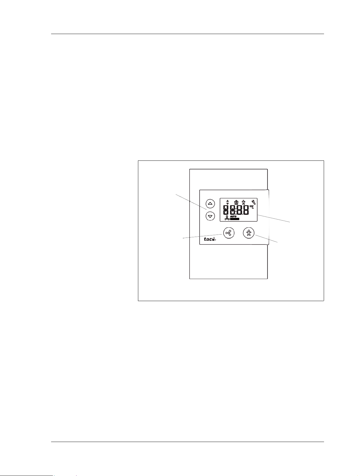
Fig. 2.1: Wall module STR150
Bypass button
Increase/Decrease
buttons
Fan speed control
Display
• Temperature setpoint adjustment. The temperature setpoint can
be adjusted, either as an absolute value or as an offset.
• Bypass or on/off button. The bypass function forces the control-
ler to comfort mode for a configurable period of time. The same
button can also be used as an on/off button.
• Mode Indicator. An On/Off symbol in the LCD indicates the
mode of the control.
See STR350/351 configuration and data sheets for more details about
the technical characteristics listed above, additional functions and configuration details.
Use the LNS plug-in to configure STR350/351.
2.2.2 STR150
STR150 is connected to TAC Xenta 104-A using two or three wires; the
third wire is used if mode indication in the LCD is required. On the other
two wires information is sent from the wall unit to the controller:
• Zone temperature. The temperature sensed by the thermistor ele-
ment.
• Temperature setpoint. The temperature setpoint is displayed as
an absolute temperature, but transmitted as an offset to the configured reference temperature.
• Bypass button. The bypass button forces the controller to comfort
mode for a fixed period of time (2h).
The mode indication signaled on the third wire is connected to the symbol of a man in the LCD:
• Comfort mode (On) is indicated by a steady symbol
Schneider Electric Buildings AB, Mar 2010 15 (74)
04-00068-01-en
Page 16
2 Zone Controller TAC Xenta 104 Zone Controller, TAC Xenta 104-A
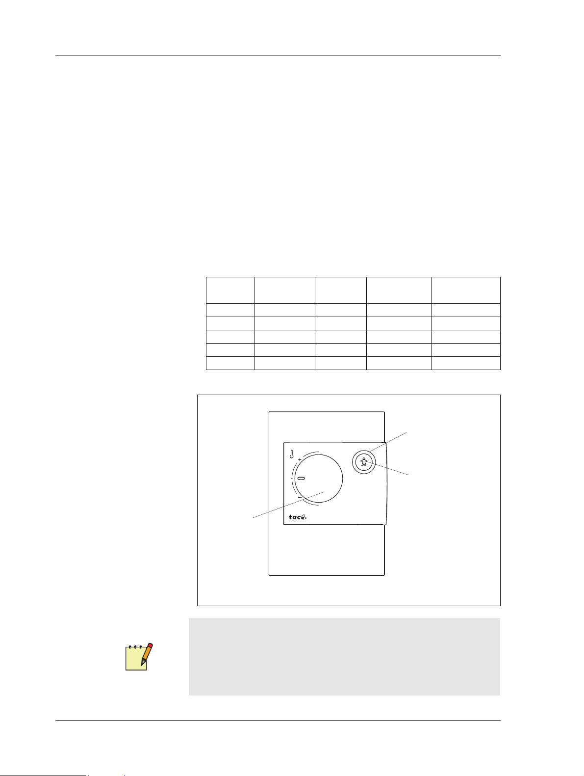
Fig. 2.2: Wall module STR104 as an example
Mode indicator
On/Off
Bypass button
Temperature
setting wheel
• Economy (Standby) mode is indicated by a flashing symbol.
• If the symbol is not shown (off) the zone is unoccupied.
There is no communication from the controller to the unit. This means
that if a setpoint is changed using TAC Vista, the new value cannot be
displayed on STR150.
STR150 is configured using the buttons and display on the unit. See
STR150 configuration and data sheets for details.
2.2.3 STR100-104
STR100-104 is a series of room units that connect to the I/O terminals
of TAC Xenta 104-A. The functionality of the various models are
shown in the Table 2.1, “STR100-104 functionality”.
Table 2.1: STR100-104 functionality
Model Temp Sensor
STR100 X
STR101 X X
STR102 X X X
STR103 X X X
STR104 X X X X
Mode
Indicator
Setpoint
Adjustment
Bypass Button
Note
• The TAC Xenta OP is normally connected directly to the controller, not the wall module. The TAC Xenta 101-VF has a TAC
Xenta OP access connecter (type RJ-10) on the controller instead
of dedicated terminals for the wall module.
16 (74) Schneider Electric Buildings AB, Mar 2010
04-00068-01-en
Page 17

Zone Controller, TAC Xenta 104-A 2 Zone Controller TAC Xenta 104
Depending on model the following functionality may also be present:
• Temperature Sensor. All models have a 1.8Kohms@25°C ther-
mistor element.
• Temperature Adjustment. The temperature setpoint can be
adjusted. Using the plastic keys on the rear of the core panel the
adjustment range can be set.
• Mode Indicator. The green LED indicates the control mode:
• Comfort mode (On) is indicated by a steady green light
• If the LED is off the zone is unoccupied.
• Bypass button. The bypass button forces the controller to comfort
mode for fixed period of time (2h).
Refer to STR100-107 data sheet and installation sheet for details.
2.2.4 Wall Module Configuration
Wall Module Choice
STR150 is enabled by nciAppOptions bit 14:
• 0 = ZS, STR100-104 or STR350/351 (default)
•1 = STR150
This can be set using the LonMaker Xenta100 plug-ins in Toolpack ver-
sion 2.01 or higher, or by means of TAC Xenta OP.
Initial Start Up Status
• SpaceTemp in the application is set to +20.00 Celsius (This can
not be read in the nviSpaceTemp, however it can be read in
nvoSpaceTemp)
• Fan is set to Fan Auto
TAC Xenta can now accept for data from the STR module.
If no room temperature readings are received within 10 minutes, the
SpaceTemp in the application is set to “invalid”. This is shown as
“invalid” in nvoSpaceTemp.
When the first update is received then the 10-minute limit is changed to
5 minutes.
Unless there is a restart, the Offset + Fan values are not cleared and the
last value is valid.
Note
• Fore more information on how to configure and engineer the
STR series of wall modules see respective product documents.
Schneider Electric Buildings AB, Mar 2010 17 (74)
04-00068-01-en
Page 18

2 Zone Controller TAC Xenta 104 Zone Controller, TAC Xenta 104-A
2.2.5 General
The controller is suitable for a variety of applications such as RTU
(Roof Top Units), small Unit Ventilators and small AHU (Air Handling
Units).
Cooling control is achieved by one or two cooling stages in sequence
based on zone temperature from the wall module.
Heating control is achieved by one or two heating stages based on zone
temperature or as an alternative tri-state valve control based on discharge air temperature.
For economizer control a sensor is connected in the mixed- or discharge
air stream depending of application.
A fan is controlled according to configuration settings.
Different configuration options can be chosen to fit both networked and
stand-alone applications.
The TAC Xenta 104 controller incorporates several features:
• a fan status switch to stop the heating and cooling functions, c an
be connected.
• an auxiliary alarm sensor can be connected.
• the fan can be configured to run continous or cycle on a call for
heating or cooling.
• A discharge air temperature sensor can be connected for controlling the discharge air temperature and the zone temperature in
cascade.
2.2.6 HVAC Controller, Network Installation
In networked applications a SNVT supplies the out-door air temperature for economizer and compressor lockout functions.
For economizer control a sensor is connected in the mixed air stream in
both two stage and tri-state modes.
For detailed description about networked applications, please see
Chapter 5.3.5, “Networked Applications”, on page 48.
In stand-alone applications the outdoor air temperature for economizer
and compressor lockout functions is supplied by a physical input.
For economizer control a sensor is connected in the discharge air stream
in both two stage and tri-state modes.
18 (74) Schneider Electric Buildings AB, Mar 2010
04-00068-01-en
Page 19
Zone Controller, TAC Xenta 104-A 2 Zone Controller TAC Xenta 104
H1 H2 C1 C2
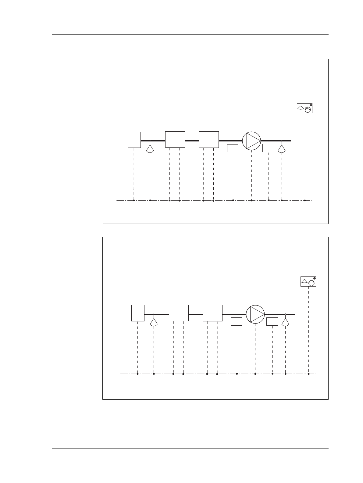
Fig. 2.3: RTU application for HVAC controller network installation
Economizer
Mixed air temperature sensor
(input B2)
Heating
stage
Cooling
stage
Alarm
Fan
Fan
Status
Discharge air temperature sensor
(optional at input U1)
Wall
module
Fig. 2.4: AHU or Unit Ventilator applications for HVAC controller
network installation
Economizer
Mixed air temperature sensor
(input B2)
Heating
stage
Cooling
stage
Alarm
Fan
Fan
Status
Discharge air temperature sensor
(input U1)
Wall
module
For detailed description about stand-alone applications, please see
Chapter 5.3.6, “Stand-alone Applications”, on page 49.
Inc. Dec. C1 C2
2.2.7 HVAC Controller, Stand-alone Installation
In stand-alone applications the outdoor air temperature for economizer
and compressor lockout functions is supplied by a physical input.
Schneider Electric Buildings AB, Mar 2010 19 (74)
04-00068-01-en
Page 20
2 Zone Controller TAC Xenta 104 Zone Controller, TAC Xenta 104-A
H1 H2 C1 C2
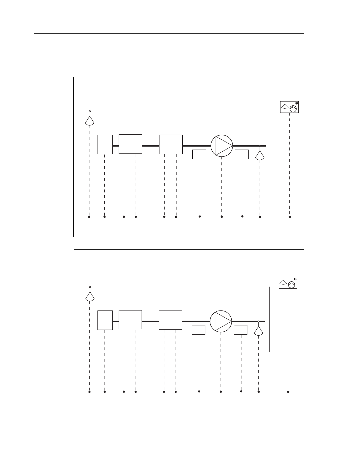
Economizer
Outdoor air
sensor
(input U1)
Heating
stage
Cooling
stage
Alarm
Fan
Fan
Status
Discharge air temperature
sensor (input B2)
Wall
module
Fig. 2.5: RTU application for HVAC controller, stand-alone
Economizer
Outdoor air
sensor
(input U1)
Heating
stage
Cooling
stage
Alarm
Fan
Fan
Status
Discharge air temperature
sensor (input B2)
Wall
module
Fig. 2.6: AHU or Unit Ventilator application for HVAC controller, stand-alone
For economizer control a sensor is connected in the discharge air stream
in both two stage and tri-state modes.
For detailed description about stand-alone applications, please see
Chapter 5.3.6, “Stand-alone Applications”, on page 49.
Inc. Dec. C1 C2
20 (74) Schneider Electric Buildings AB, Mar 2010
04-00068-01-en
Page 21
Zone Controller, TAC Xenta 104-A 3 Installation
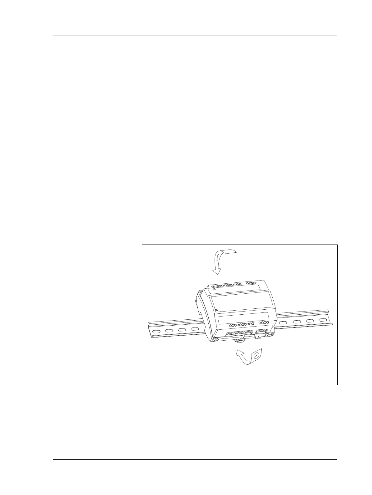
Fig. 3.1: TAC Xenta 104-A fixed on a DIN rail
3 Installation
3.1 Mechanical Installation
3.1.1 Fitting
The TAC Xenta 104-A can either be snapped onto a DIN rail (Fig. 3.1)
or fixed to a level surface with two screws. (Fig. 3.2).
Fastening the controller onto a DIN rail:
1 Place the controller on the top of the rail as shown by arrow 1.
2 Twist the controller downwards until it snaps onto the rail as
shown by arrow 2.
3 T o remove use place a screwdriver to locate the lock on the bottom
of the controller and pull down. Lift the controller diagonally
upwards and off the rail.
Schneider Electric Buildings AB, Mar 2010 21 (74)
04-00068-01-en
Page 22
3 Installation Zone Controller, TAC Xenta 104-A
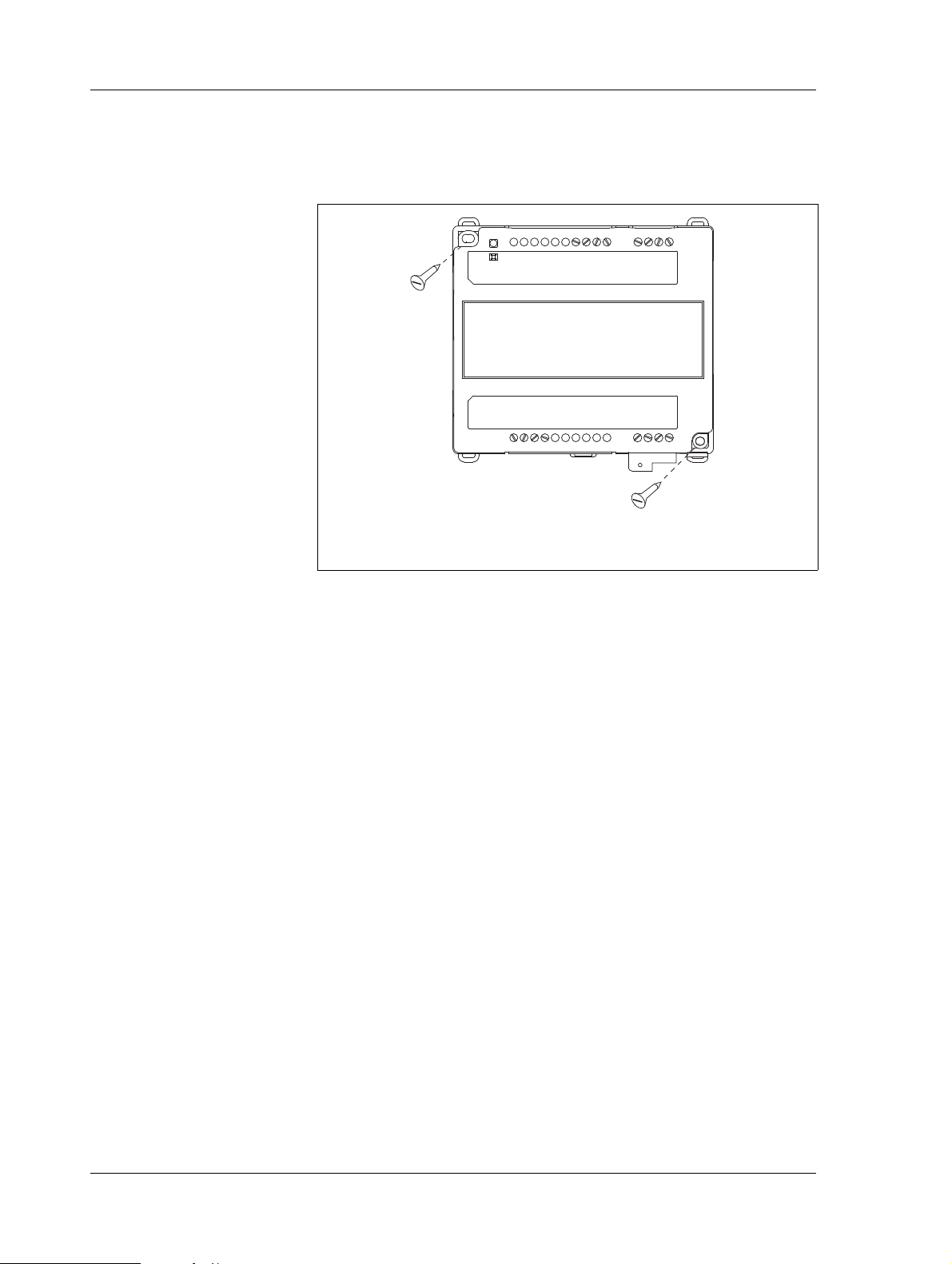
Fig. 3.2: TAC Xenta 104-A fixed to a level surface
Fixing the controller to a level surface:
Use the two sockets provided for fixing the controller; the maximum
screw size is M4 or ST 3,5 (Ø 0.15"). The head of the screw should not
exceed 7,5 mm (0.3") in diameter.
3.2 Electrical Installation
3.2.1 General
1 Each controller or group of controllers must use max. 6 A fuses.
2 Avoid hanging or loose cables by using clamps to secure them to
the controller.
3 A switch to cut off the power supply to the controller or compete
unit must be easily accessible.
4 Connect U1 and M with a jumper when not used.
5 When several Xenta controllers receive power from a common
transformer, it is important that all Gs are connected to each other
and that all G0s are connected to each other. They must not be
interchanged. An important exception: G0 on the wall module
should not be connected with the other G0’s. Instead it should be
connected to the terminal OP on the controller. At the transformer,
G0 should be connected to protective earth. This is to get an
grounding point for interference diversion.
6 To ensure that the specified measuring accuracy is achieved, the
two M terminals must be connected to the wall module.
NOTE: This equipment has been tested and found to comply with the
limits for a Class B digital device, pursuant to part 15 of the FCC Rules.
22 (74) Schneider Electric Buildings AB, Mar 2010
04-00068-01-en
Page 23

Zone Controller, TAC Xenta 104-A 3 Installation
These limits are designed to provide reasonable protection against
harmful interference in a residential installation. This equipment generates, uses and can radiate radio frequency energy and, if not installed
and used in accordance with the instructions, may cause harmful interference to radio communications. However, there is no guarantee that
interference will not occur in a particular installation. If this equipment
does cause harmful interference to radio or television reception, which
can be determined by turning the equipment off and on, the user is
encouraged to try to correct the interference by one or more of the following measures:
• Reorient or relocate the receiving antenna.
• Increase the separation between the equipment and receiver.
• Connect the equipment into an outlet on a circuit different from
that to which the receiver is connected.
• Consult the dealer or an experienced radio/TV technician for help.
Safety Standard
Transformers supplying the controller must comply to the safety standard EN 60 742 or any other relevant safety standard for ELV, 24 V AC.
ETL listing: UL 3111-1, first edition and CAN/CSA C22.2 No. 1010.1-
92. When connecting equipment that has an independent power supply,
the power supply must also comply with this norm.
Cable Lengths
For information on communication cable lengths, see TAC Xenta Network Guide, part number 0-004-7460. For all other cables, maximum
length is 30 m (100 feet) and min. area is 0,7 mm
2
(AWG-19).
The Wall Modules
The STR100-104 is primarily intended for use with the Xenta 104-A.
For more information about how to connect and configure wall modules, please refer to the documentation for each respective product.
Schneider Electric Buildings AB, Mar 2010 23 (74)
04-00068-01-en
Page 24

3 Installation Zone Controller, TAC Xenta 104-A
Connection Terminals
The designation of the connection terminals can be seen in two places
on the controller: on the edge of the printed circuit board, and on the
label on the front of the controller.
Table 3.1: Connection Terminals
Termin. Design. Function Type
1 C1 TP/FT-10 communication channel -
2 C2 TP/FT-10 communication channel -
3 X3 Alarm (option) Digital input
4 M Measurement neutral -
5 X2 Fan status Digital input
6 B2 Discharge/mixed air temperature sensor Thermistor input
7 M Measurement neutral -
8 U1 OA/discharge air temperature
9 D1 LED on wall module Digital output
10 M Measurement neutral -
11 X1 Bypass button on wall module Digital input
12 R1 Setpoint offset dial on wall module 10 k
sensor Thermistor input
Ω linear potentiometer
13 M Measurement neutral -
14 B1 Room temperature sensor Thermistor input
15 G 24 V AC (G) Input
16 G0 24 V AC (G0) Input
a
17
18 G 24 V AC supply for TAC Xenta OP -
19 V1 Heating actuator: increase Triac output
20 VC1 24 V AC (G) supply for V1, V2 -
21 V2 Heating actuator: decrease Triac output
22 V3 Cooling stage 1 1st stage output
23 VC2 24 V AC (G) supply for V3, V4 -
24 V4 Cooling stage 2 2nd stage output
25 M Measurement neutral -
26 Yl Economizer actuator Analog output
27 K1 Fan relay Relay output
28 KC1 Fan relay Relay output
OP 24 V AC supply for TAC Xenta OP -
a. Connected to G0 on the wall module. Do not connect to G0 on the controller.
24 (74) Schneider Electric Buildings AB, Mar 2010
04-00068-01-en
Page 25

Zone Controller, TAC Xenta 104-A 3 Installation
20
VC1
Junction Box
3
2
1
24 VAC
G0
C
Ty pical RTU
Te r minal Str
ip
R
G
15
16
Heat
Stage 1
W1
G
OP
17
18
19
V1
C2
TAC Xenta
104-A
C1
1
2
X3
3
4
X2
5
6
Lon Talk
TP/FT-10
FAN
24
Stage 1
Heat
Stage 2
W2
Cool
Y1
22
21
V2
23
V3
VC2
Efma24
actuator
Cool
Stage 2
Y2
econ
G
V4
25
Y1
26
27
K1
KC1
28
10
8
7
B2
9
U1
D1
X1
11
R1
12
13
B1
14
Alarm
Fan
Status
Mixed air*/Discharge air**
Fan
Relay
Typical RTU
or HVAC Unit Connections
* When networked
** When stand-alone
Discharge air*/Outdoor air**
M
M
M
M
M
STR101-1
04
G
OP
C1
C2
Wall Module
12
11
13
14
15
16
M
LED
Pot/Pot+R
Mx
Switch
Therm
23
24
21
22
Fig. 3.3: Wiring of TAC Xenta 104: typical RTU or HVAC unit
3.2.2 Wiring of TAC Xenta 104 as Typical RTU or HVAC Unit
Read Chapter 3.2.1, “General”, on page 22 before you connect the
cables as shown in the wiring diagram in Fig. 3.3.
Schneider Electric Buildings AB, Mar 2010 25 (74)
04-00068-01-en
Page 26

3 Installation Zone Controller, TAC Xenta 104-A
15
G
16
G0
17
OP
18
G
19
V1
20
VC1
21
V2
22
V3
23
VC2
24
V4
25
26
Y1
27
K1
28
KC1
1
2
3
4
5
6
7
8
9
10
12
13
14
C1
C2
X3
X2
B2
U1
D1
X1
R1
B1
G
R
C
Y1
Y2
Cool
Stage 2
Cool
Stage 1
Efma24
actuator
econ
FAN
Junction Box
COM
TAC Xenta
104-A
3
2
1
INC.
Actuator,
heating valve
DEC.
Alarm
Fan Status
Fan
Typical RTU
Terminal
Lon Talk
TP/FT-10
Typical Packaged RTU
Cooling only with reheat valve
24 VAC
* When networked
** When stand-alone
Discharge air*/Outdoor air**
Mixed air*/Discharge air**
M
M
M
M
M
11
STR101-104
G
OP
C1
C2
Wall Module
12
11
13
14
15
16
M
LED
Pot/Pot+R
Mx
Switch
Therm
23
24
21
22
Fig. 3.4: Wiring of TAC Xenta 104: typical packaged RTU
3.2.3 Wiring of TAC Xenta 104 as Typical Packaged RTU
Read section Chapter 3.2.1, “General”, on page 22 before you connect
the cablesas shown in the wiring diagram in Fig. 3.4.
26 (74) Schneider Electric Buildings AB, Mar 2010
04-00068-01-en
Page 27

Zone Controller, TAC Xenta 104-A 3 Installation
20
VC1
Junction Box
Actuator,
Heating v
alve
24 VAC
Size Transformer
For Total Load
G0
G
15
16
G
OP
17
18
19
V1
C2
C1
1
2
X3
3
4
X2
5
6
Lon Talk
TP/FT-10
FAN
24
Cond. Unit
COM
Y1
R
22
21
V2
23
V3
VC2
Efma24
actuator
Y2
econ
V4
25
Y1
26
27
K1
KC1
28
Controller Applied to Small AHU
or Unit Ventilator
10
8
7
B2
U1
D1
9
X1
1
1
R1
12
13
B1
14
3
2
1
DEC.
INC.
Alar
Fan
Status
Fan Relay
TAC Xenta
104-A
* When networked
** When stand-alone
Discharge air*/Outdoor air**
Mixed air*/Dischargeair**
STR101-104
G
OP
C1
C2
Wall Module
12
11
13
14
15
16
M
LED
Pot/Pot+R
Mx
Switch
Therm
23
24
21
22
Fig. 3.5: Wiring of TAC Xenta 104:
controller applied to small AHU
3.2.4 Wiring of TAC Xenta 104 as Controller Applied to Small AHU
Read section 3.2.1 “General” before you connect the cables as shown in
the wiring diagram in Fig. 3.5.
Schneider Electric Buildings AB, Mar 2010 27 (74)
04-00068-01-en
Page 28

3 Installation Zone Controller, TAC Xenta 104-A
Fig. 3.6: Connecting to STR150
3.2.5 Connecting to STR150
Wall Module
STR150
1
C1
TAC Xenta
104-A
G
15
3.3 Commissioning
3.3.1 General
Once the mechanical and electrical installations have been completed
the controller can be commissioned. This means:
• Installing the controller on the network, setting the node status and
giving it an address.
Mode
11 1213
4
3
2
C2
X3
OP
G0
17
16
5
X2
M
G
V1
19
18
7
6
M
B2
VC1
V2
20
21
9
8
D1
U1
VC2
V3
23
22
Data
M
12
11
10
M
V4
24
R1
X1
Y1
M
26
25
14
13
M
B1
KC1
K1
28
27
28 (74) Schneider Electric Buildings AB, Mar 2010
• Setting the controller's configuration parameters.
• Bind network variables.
• Test the functions.
Before commissioning a complete zone system, read the “TAC Xenta Zone Systems Guideline”.
The TAC Xenta OP can be used to set the basic parameters. Use a network management tool or TAC Vista for commissioning the controller
on the network.
How to use the TAC Xenta 100 as a stand-alone unit:
1 Use TAC Xenta OP to set the node status to "Configured".
2 Use TAC Xenta OP to set the basic parameters.
3 Use TAC Xenta OP to set all other parame ters and variables.
Commissioning can also be achieved using a network management tool.
04-00068-01-en
Page 29

Zone Controller, TAC Xenta 104-A 3 Installation
3.3.2 Node Status
The node status indicates which network configuration or program
mode the controller is in. The node status can be changed using
TAC Vista (version 3.1 or later) and the network management tool.
TAC Xenta OP can also be used on some occasions. The controller can
be in these states:
Unconfigured
The controller is not configured when it leaves the factory. Neither the
program nor the network communication are running. The service light
emitting diode is flashing.
The controller must be configured before it can operate in a network (on
line) see below.
You cannot set configuration parameters or network variables in this
state.
Configured, Online
Use the TAC Xenta OP, TAC Vista or a network management tool to
change the status to configured. When this has been done, the program
and the network communication will be fully operational. The service
LED is off. This is the normal state for a controller when it is operating.
The controller will use the address given by the tool during configuration. As TAC Xenta OP cannot be used to set an address, all controllers
are given a default address. Therefore all controllers get default
addresses. This means that TAC Xenta 100 can only be used as a standalone controller and cannot be used in a network.
The parameters and variables can now be set.
Configured, Soft Online
A network management tool is needed for this operation. The controller
is programed and configured for a network, but the program and communications are idle. The light emitting diode is off. If the controller is
reset, it will go into configured, online.
Configured, Hard Online
A network management tool is needed for this operation. The controller
is programed and configured for a network, but the program and communications are idle. The light emitting diode is off. If the controller is
reset, it will remain in this state.
Without a Program and Not Configured
This states indicates that there is something wrong with the controller.
No program can be detected. The light emitting diode is lit.
Schneider Electric Buildings AB, Mar 2010 29 (74)
04-00068-01-en
Page 30

3 Installation Zone Controller, TAC Xenta 104-A
3.3.3 Configuration Parameters (nci’s)
TAC Xenta 100 has a number of configuration parameters that can be
used to set the parameters of the controller. See Chapter 4, “Configuration Parameters”, on page 33. There are also network variables to control the controller during when it is operating.
Use the commissioning protocol in Appendix B to write down your settings when commissioning. Chapter 8, “Communication”, on page 59
contains information about all parameters and variables, such as their
index, accepted values, normal values. Detailed descriptions of the
parameters and variables can be found in Chapter 4, “Configuration
Parameters”, on page 33, in Chapter 5, “Functional Description”, on
page 39 and in Chapter 6, “Troubleshooting”, on page 53.
3.3.4 Network Installation
For network installation, you need either a network management tool
(LNS based or not) or TAC Vista. Examples of network management
tools are MetraVision and ICELAN-G. Here you find brief information
on how this is made.
The installation has two steps:
1 Feed information about the controllers’ unique neuron-ID into the
network management tool’s data base.
2 Allow the network management tool to install the controller on the
network. The controller will automatically be given an addre ss.
There are two ways to feed the neuron-ID into the data base:
1 Manually feed the neuron-ID into the network management tool.
To make this easier you can use a bar code reader to read the
detachable ID-neuron label that is attached to every controller. It
can be a good idea to collect these labels when you make the basic
configuration, and stick them to a form, drawing or similar. There
is a form for this purpose in the manual “TAC Xenta, Guidelines
for zone applications” .
2 Use the service pin function. You can only do this when the con-
troller is connected to the network. There is a service pin key in a
hole in the upper left hand corner of the controller by terminal C1.
Push the key to instruct the controller to send out its neuron-ID.
The network management tool can then read the neuron-ID from
the network and save it in its data base.
Fore more information see “TAC Xenta, Guidelines for zone applications”.
3.3.5 Network Variable Binding
The binding method is determined by the type of network management
tool to be used. Detailed information can be found in the tool’s docu-
30 (74) Schneider Electric Buildings AB, Mar 2010
04-00068-01-en
Page 31

Zone Controller, TAC Xenta 104-A 3 Installation
mentation. A description of how network variables are bound with
Metra Vision can be found in the "TAC Xenta Network manual".
Binding network variables is not an issue when the controller is used in
a stand-alone operation.
3.3.6 Function Test
Check that the controller works as intended.
All the controller’s functions are described in Chapter 5, “Functional
Description”, on page 39.
Trouble-shooting is described in Chapter 6, “Troubleshooting”, on
page 53.
Schneider Electric Buildings AB, Mar 2010 31 (74)
04-00068-01-en
Page 32

3 Installation Zone Controller, TAC Xenta 104-A
32 (74) Schneider Electric Buildings AB, Mar 2010
04-00068-01-en
Page 33

Zone Controller, TAC Xenta 104-A 4 Configuration Parameters
4 Configuration Parameters
All communication with the controller is made using network variables.
• nci’s are used to configure the controller. nci’s are normally set
during commissioning, and are not altered during normal operation (the parameters are stored in a special memory, and can be
changed a maximum of 10 000 times).
• nvi’s control the controller during operation,
• nvo’s are output variables, which the controller sends out on the
network.
Chapter 8, “Communication”, on page 59 contains detailed information
about accepted values and normal values for all parameters. All configuration parameters have default values on delivery.
Schneider Electric Buildings AB, Mar 2010 33 (74)
04-00068-01-en
Page 34

4 Configuration Parameters Zone Controller, TAC Xenta 104-A
4.1 Basic Parameters
nciAppOptions
These parameters are used to set selectable functions in the controller.
The parameter consists of 16 bits, where each bit represents one function choice. The bits 10 through 13 are not used. When you look at
nciAppOptions with TAC Xenta OP, bit 0 is shown to the left.
Table 4.1: The function of different bits in nciAppOptions.
Bit no. Function
Bit 0 Not used
Bit 1 Not used
Bit 2 0 2-stage heating
1 Tri-state heating
Bit 3 0 Fan cycling on room temperature
1 Continuous fan
Bit 4 0 Read outdoor temperature (U1)
1 Read SNVT nviOutsideTemp
Bit 5 0 Read outdoor or discharge temperature. Econo Lockout using nviOutsideTemp (Deg).
1 Read enthalpy value. Econo Lockout using nviOutsideTemp (Ent).
Bit 6 - 13 Not used
Bit 14 0 ZS, STR101-104 or STR350/351wall modules
1 STR150 wall module with display
Bit 15 Reserved for production test. Should not be altered!
Bit 6 through bit 13 are not used.
34 (74) Schneider Electric Buildings AB, Mar 2010
04-00068-01-en
Page 35

Zone Controller, TAC Xenta 104-A 4 Configuration Parameters
4.2 Other Configuration Parameters
The controller’s other configuration parameters are listed below
together with a short description. See also Chapter 8, “Communication”, on page 59.
Index Name Description
0 nciLocation Location label
18 nciSetpoints Occupancy temperature setpoints
19 nciSpaceTempLow Low limit of zone temperature
20 nciSpaceTempHigh High limit of zone temperature
21 nciSpaceTempOfst Offset of zone temperature
22 nciGainEcon Gain for economizer controller
23 nciItimeEcon Integral time economizer controller
24 nciGainHeat Gain for heating controller
25 nciItimeHeat Integral time heating controller
26 nciGainCool Gain for cooling controller
27 nciItimeCool Integral time cooling controller
28 nciClgLocStpt Cooling lock-out setpoint
29 nciEcoLocStptDeg Economizer lock-out setpoint degrees
30 nciEcoLocStptEnt Economizer lock-out setpoint enthalpy
31 nciEconoMin Minimum position economizer
32 nciHeatActStTime Stroke time for heating actuator
33 nciShrtCycleTime Minimum compressor intervals
34 nciMixAirTempLow Low limit of temperature for mixed air
35 nciDischAirMin Min. limit discharge air
36 nciDischAirMax Max. limit discharge air
37 nciInstallType Source for network configuration
38 nciSndHrtBt Send heartbeat
39 nciRcvHrtBt Receive heartbeat
nciLocation
nciLocation is used to make a label for the actual place where the controller is installed. In the operating panel, this parameter is shown as the
first variable.
nciSetpoints
nciSetpoints is used to set the setpoint temperatures for heating and
cooling in the different operation modes: occupied and off mode (see
section Section 5.2.1, “Operation Modes”, on page 40 and
Section 5.2.4, “Setpoint Calculation”, on page 43).
Schneider Electric Buildings AB, Mar 2010 35 (74)
04-00068-01-en
Page 36

4 Configuration Parameters Zone Controller, TAC Xenta 104-A
nciSpaceTempLow, nciSpaceTempHigh
nciSpaceTempLow and nciSpaceTempHigh are used to set an alarm setpoint, lowest and highest zone temperatures. Default value 50/86 °F
(10/30 °C).
nciSpaceTempOfst
nciSpaceTempOfst is used to adjust the reading from the temperature
sensor or nviSpaceTemp. Default value 0.
nciGainEcon, nciGainHeat, nciGainCool
nciGainEcon, nciGainHeat and nciGainCool are used for setting the
gain for the economizer and heating/cooling controllers. Default value
25.
nciItimeEcon, nciItimeHeat, nciItimeCool
nciItimeEcon, nciItimeHeat and nciItimeCool are used to sett the I-time
for the economizer and heating/cooling controllers. Default value 900 s
(15 min).
nciClgLocStpt
nciClgLocStpt is used to set the cooling lock-out setpoint.
nciEcoLocStptDeg, nciEcoLocStptEnt
nciEcoLocStptDeg and nciEcoLocStptEnt contains the lock-out setpoints for the economizer, in degrees and enthalpy. Default values 64 °F
/ 0 (18 °C / 0).
nciEconoMin
nciEconoMin contains the minimum position for the economizer
damper. Default value 0%.
nciHeatActStTime
nciHeatActStTime is set according to the stroke time of the actuator.
nciShrtCycleTime
nciShrtCycleTime is used to set a minimum allowed time between compressor run sessions.
nciMixAirTempLow
Alarm setpoint for low mixed air temp. Default value 46 °F (8 °C).
nciDischAirMin, nciDischAirMax
nciDischAirMin and nciDischAirMax are used to set the allowed maximum/minimum temperatures. Effective in cascade tri-state control as
well as two stage (see Section 5.3.2, “Cooling”, on page 46). Default
values 50/95 °F (10/35 °C).
36 (74) Schneider Electric Buildings AB, Mar 2010
04-00068-01-en
Page 37

Zone Controller, TAC Xenta 104-A 4 Configuration Parameters
nciInstallType
nciInstallType is only used during free-standing operation and is set to
show that the node itself should define its address (see Section 8.5.3,
“The Node Object’s Configuration Parameters (nci)”, on page 62).
nciSndHrtBt
nciSndHrtBt is used to decide how often the nvo’s, which are sent out
on the network regularly, should be sent (see Section 8.3, “Monitoring
Network Variables, Heartbeat”, on page 60).
nciRcvHrtBt
nciRcvHrtBt is used to decide the maximum time there can be between
updating the nvi’s, for which the controller expects continuous updating
(see Section 8.3, “Monitoring Network Variables, Heartbeat”, on
page 60).
Schneider Electric Buildings AB, Mar 2010 37 (74)
04-00068-01-en
Page 38

4 Configuration Parameters Zone Controller, TAC Xenta 104-A
38 (74) Schneider Electric Buildings AB, Mar 2010
04-00068-01-en
Page 39

Zone Controller, TAC Xenta 104-A 5 Functional Description
5 Functional Description
5.1 General
The controller’s function is determined by its node status (Section 3.3.2,
“Node Status”, on page 29), operations (Section 5.2.1, “Operation
Modes”, on page 40) and the methods used to force the controller
(Section 5.2.2, “Application and Emergency Modes”, on page 41) for
well-adapted zone temperature control.
The controller measures the zone temperature, the outside or mixed air
temperature and uses various methods to calculate setpoints. Apart from
the basic functions the controller can also use a variety of methods to
control the climate in the zone. These are described in Section 5.3,
“More About Functions”, on page 45.
Each section in this chapter ends with information about how network
variables are used in the current control situation. If you need details
about the network variables’ characteristics, such as default values and
accepted values see Chapter 8, “Communication”, on page 59.
Schneider Electric Buildings AB, Mar 2010 39 (74)
04-00068-01-en
Page 40

5 Functional Description Zone Controller, TAC Xenta 104-A
5.2 The Controller’s Basic Functions
5.2.1 Operation Modes
The controller has three operation modes:
•Occupied
• Bypass
• Unoccupied
The operation mode is controlled by nviManOccCmd, but is also influ-
enced by the bypass button on the wall module. The relationship
between operation modes is shown in Table 5.1, “The relationship
between desired operation, bypass timer and current operation mode.”
The controller’s values during stand-alone operation are also shown.
Table 5.1: The relationship between desired operation, bypass timer and current operation mode.
Desired operation
nviManOccCmd
Occupied OC_OCCUPIED
OC_OCCUPIED
Unoccupied Enabled OC_BYPASS
OC_UNOCCUPIED At a stand-still OC_UNOCCUPIED
Stand-alone OC_OCCUPIED
OC_NUL
a. Activated by the bypass button on the wall module
Bypass timer
a
nvoEffectOccup
Occupied Mode
Occupied Mode is default mode that is to say when someone is in the
zone the controller should ensure that the climate in the room is comfortable. The controller is in this mode when nviManOccCmd =
OC_OCCUPIED (or OC_NUL after a power down).
The LED on the wall module is lit with a steady red light and the setpoint knob on the wall module can be used to make manual settings. The
setpoints used are found in nciSetpoints (can be modified).
The fan is on continously or during heating/cooling.
Bypass Mode
Change temporarily from unoccupied to occupied mode using the
bypass button on the wall module.
The nviOccManCmd variable is used to bypass an old value, which is
stored, and start a timer, which will run according to nciBypassTime.
When nciBypassTime has elapsed, nviOccManCmd resumes it’s previous state.
40 (74) Schneider Electric Buildings AB, Mar 2010
04-00068-01-en
Page 41

Zone Controller, TAC Xenta 104-A 5 Functional Description
Heating
Case
Cooling
Case
Heating
Setpoint
Cooling
Setpoint
Cooling
Demand
Fig. 5.1: Changeover between heating and cooling cases
If the nviOccManCmd SNVT is updated thi s will have a higher priority,
and the Bypass mode is left.
To avoid this, the nvo bound to the nviOccManCmd should not propagate on periond (set to 0). Only on Delta.
Unoccupied Mode
When the zone is not used for a longer period of time, the controller can
be set in unoccupied mode. The controller is in this mode when nvi-
ManOccCmd = OC_UNOCCUPIED.
The light emitting diode on the wall module is out, and the fan is off, if
there is no demand for heating or cooling. In such cases, the fan is running. The setpoint knob is blocked, but the bypass button is not. The setpoints used are found in nciSetpoints, unoccupied mode.
Index Variable name Description
1 nvoEffectOccup Actual occupancy output
14 nviManOccCmd Occupancy scheduler input
18 nciSetpoints Occupancy temperature setpoints
5.2.2 Application and Emergency Modes
TAC Xenta 104-A is designed to control both heating, cooling, economizing, and to automatically change from heating to cooling as necessary..
You can force the controller to heat only or cool only, just as you can
force it to neither heat nor cool, and to run the fan only. This is achieved
using nviApplicMode, see Table 5.2, “The relation between nviApplicMode and forcing.”.
Table 5.2: The relation between nviApplicMode and forcing.
nviApplicMode Mode Description
HVAC_AUTO Automatic (no forcing) The controller automatically change s over b etween heating and cooling
HVAC_HEAT Heating only The controller can only heat. The cooling setpoint is neglected.
HVAC_COOL Cooling only The controller can only cool. The heating setpoint is neglected.
Schneider Electric Buildings AB, Mar 2010 41 (74)
04-00068-01-en
Page 42

5 Functional Description Zone Controller, TAC Xenta 104-A
Table 5.2: The relation between nviApplicMode and forcing.
nviApplicMode Mode Description
HVAC_FAN_ONLY Fan only The controller neither cools nor heats. The fan is running constantly.
HVAC_OFF Off The controller neither cools nor heats. The fan is at a stand-still.
Emergency Mode
In some situations, the damper has to be forced fully opened or closed.
This is done with nviEmergCmd. The heating and fan control are disabled in emergency mode. The emergency mode has higher priority
than all the other modes.
Table 5.3: The relation between nviEmergCmd and forcing.
nviEmergCmd Description
EMERG_NORMAL Normal control
EMERG_SMOKE_PURGE Fully open damper (100%)
EMERG_SHUTDOWN Fully closed damper (0%)
Index Variable name Description
10 nviApplicMode Application mode input
11 nviEmergCmd Emergency command input
5.2.3 Measuring Zone Temperature
You can measure the zone temperature either with a permanent thermistor sensor (usually the wall module) or with a LonTalk temperature
sensor node connected to nviSpaceTemp. If nviSpaceTemp has a valid
value the controller will use it, if it doesn't the thermistor value will be
used. The thermistor value (or a value from the network) can be
adjusted by nciSpaceTempOfst having received a value; the value is
added to the thermistor value. The value the controller uses is also put
out on nvoSpaceTemp. If neither value is valid, nvoSpaceTemp will
receive the off value.
nvoSpaceTemp is sent when it has changed by at least 0.1°C.
Table 5.4: Measuring Zone Temperature
Index Variable name Description
6 nvoSpaceTemp Zone temperature output
12 nviSpaceTemp Zone temperature input
21 nciSpaceTempOfst Zone temperature sensor adjustment
42 (74) Schneider Electric Buildings AB, Mar 2010
04-00068-01-en
Page 43

Zone Controller, TAC Xenta 104-A 5 Functional Description
5.2.4 Setpoint Calculation
Zone Temperature Setpoints
nciSetpoints define four temperature setpoints; heating setpoint occupied mode, cooling setpoint occupied mode, heating setpoint unoccupied mode and cooling setpoint unoccupied mode.
The smallest accepted deviation between the heating and cooling setpoints is 0.5 °C, and the heating setpoints must be lower than the cooling setpoints. If the heating setpoints are higher or equal to the cooling
setpoints, the controller resets the heating setpoint to 0,5 °C lower than
the cooling setpoint. Table 5.5, “The setpoints in nciSet points” shows
accepted values and default values for the four temperature setpoints in
nciSetpoints.
The setpoints for occupied mode are basic setpoints, which can be
changed with nviSetpoint, nviSetPntOffset and the setpoint knob. The
unoccupied mode setpoints are always valid.
Table 5.5: The setpoints in nciSetpoints
Setpoint Min. Max. Normal
Cooling setpoint occupied 10 °C 35 °C 24 °C
Heating setpoint occupied 10 °C
Cooling setpoint unoccupied 10 °C 35 °C 28 °C
Heating setpoint unoccupied 10 °C
a. If the cooling setpoint is 10 °C, the heating setpoint is set to 9,5 °C.
a
a
35 °C 22 °C
35 °C 16 °C
Calculation
The current setpoint, nvoEffectSetpt, depends on the current operation
mode, nvoUnitStatus, the desired operation mode, nviApplicMode, and
nviSetpoint, nviSetpntOffset, nciSetpoints and a possible local setpoint
adjustment via the wall module.
nviSetpoint is used to allow the temperature setpoints in occupied mode
to be changed via the network. If there is a valid value on nviSetpoint,
the controller uses this value as a new basic setpoint when calculating
effective setpoints. Heating and cooling setpoints will thus be half of the
deadband ((Occupied Heat – Occupied Cool)/2) apart from nviSetpoint.
nviSetPntOffset can be seen as a setpoint adjustment from a wall module
connected to the network. Its value is added to setpoints for occupied
mode.
Index Variable name Description
2 nvoUnitStatus Unit status output
5 nvoEffectSetpt Actual setpoint output
10 nviApplicMode Application mode input
13 nviSetPoint Temperature setpoint input
14 nviSetPntOffset Setpoint offset input
Schneider Electric Buildings AB, Mar 2010 43 (74)
04-00068-01-en
Page 44

5 Functional Description Zone Controller, TAC Xenta 104-A
Heating
Cooling
Cooling demand
100%
0%
Fig. 5.2: Control sequence for TAC Xenta 104-A without economizer
Neutral
zone
Heating
Cooling
Cooling demand
100%
0%
Economizer lockout
Economizer
Output
Fig. 5.3: Control sequence for TAC Xenta 104-A with economizer
Index Variable name Description
18 nciSetpoints Occupancy temperature setpoints
5.2.5 Control Sequence with TAC Xenta 104-A
Without Economizer
The zone temperature is controlled by one or two stages, which either
heats or cools. The fan is normally only on during heating or cooling,
but can also be configured to run continously. Figure 5.2 shows the control sequence:
5.2.6 Fan Control
With Economizer
The zone temperature is controlled by a combination of one or two
stages of heating and cooling aided by an economizer.
The fan can be in two different modes, chosen in bit 3 of
nciAppOptions:
Continuous Operation
The fan is on continuously during occupied and by pass modes.
44 (74) Schneider Electric Buildings AB, Mar 2010
Cycling with Heating/Cooling
When fan configuration is set for cycling, the fan will be off until the
zone temperature controller calls for heating or cooling and the zone
04-00068-01-en
Page 45

Zone Controller, TAC Xenta 104-A 5 Functional Description
Heating
Cooling
Cooling demand
100%
0%
Economizer lockout
Economizer
Output
Neutral zone
Fig. 5.4: Control sequence for TAC Xenta 104-A with economizer
temperature and effective setpoint deviates more than 0.5 °C. The fan
will be turned off when the deviation is less than 0.2 °C.
Index Variable name Description
17 nciAppOptions Application options
5.3 More About Functions
5.3.1 Heating
General
When the zone temperature falls below the present heating setpoint,
heating outputs will be staged On in sequence. If tri-state heating is
selected, the increase output will begin to pulse On to open the tri-state
heating valve. When the heating setpoint is satisfied, the two stage heating outputs will sequence off. If tri-state heating is selected, the
decrease output will begin to pulse On to close the tri-state heating
valve. When the zone temperature rises above the present cooling setpoint, cascade mixed air temperature control will modulate the economizer damper if the economizer is enabled via the floating lockout
setpoint. When the economizer reaches 100%, or if the economizer is
locked out, the two cooling outputs will be staged On in sequence. This
cooling sequence is reversed as the room temperature falls below the
cooling setpoint.
Staged Heating Control
The heating outputs are controlled by a PI regulator that looks at room
temperature as its input. If heating is allowed it will sequence on the two
outputs. The heating outputs do not have a fixed delay set point. The
timing and delay function is a result of the PI regulator.
Tri-state Heating Control
Schneider Electric Buildings AB, Mar 2010 45 (74)
04-00068-01-en
The heating outputs can be configured as tri-state control for controlling
a heating valve in Unit Ventilator or small AHU applications. When tristate is selected and the outdoor temp. is supplied as an NV (in a net-
Page 46

5 Functional Description Zone Controller, TAC Xenta 104-A
worked system), the heating controller looks at the sensor connected to
terminal U1.
When used as a stand alone controller (U1 used for outdoor air), the
heating controller instead looks at the sensor connected to terminal B2
and uses this value for heating as well as economizer control.
If a thermal actuator is used for heating and some modulation is desired
then it must be connected to the increase output. Also the P and I band
must be set very low to cause the output to be operating as soon as a
need for heat exists. When heating demand is 100% the output will be
on continually.
Lockout
The heating control is locked out on a loss of fan p roof. If tri-state heating control is selected, tri-state valve control remains enabled for heating coil protection.
Heating controller
Type: PI
Gain: 0-32,75; normal value: 25
I-time: 0-60 minutes; normal 15 minutes
Dead band: 0,2 °C
Run time: 5-600 s; normal 165 s
Control interval: 15 s
5.3.2 Cooling
Control
The cooling outputs are controlled by a PI regulator that uses room temperature as its input. If cooling is allowed and outdoor temperature is
above cooling lockout setpoint it will sequence on the two outputs. The
outputs have an adjustable anti-cycle timer for short cycle protection.
An NV is available to read on the network to indicate the percent of
cooling called for by the cooling regulator. The PI regulator tuning
parameters can be adjusted via the TAC Xenta OP or an NV.
Night Free Cooling Mode
This can be accomplished by sending the opertaing mode “cooling
only”, then sending an NV for reduced room temperature set-points, and
sending an NV for cooling lockout.
46 (74) Schneider Electric Buildings AB, Mar 2010
04-00068-01-en
Page 47

Zone Controller, TAC Xenta 104-A 5 Functional Description
Lockout
If the outdoor temperature sensor is connected and configured it will be
used to determine cooling lockout. Cooling is locked out on a loss of fan
proof.
Cooling controller
Type: PI
Gain: 0-32.75; normal value: 25
I-time: 0-60 minutes; normal 15 minutes
Dead band: 0.2 °C
Run time: 5-600 s; normal 165 s
Control interval: 15 s
5.3.3 Economizer
Control
The economizer will only function in the cooling or Auto changeover
modes. The economizer will stay at the minimum position setpoint
while heating in occupied or bypass mode. In unoccupied mode, the
damer is closed. The economizer output is controlled via a PI regulator
that normally uses the sensor connected to B2 as its input.
The economizer is active during cooling. There is a built in software
lock to hold the economizer at 100% outdoor air position if the outdoor
air is useful for cooling when any stage of mechanical cooling is on.
This will provide maximum energy savings and prevent economizer
damper hunting when the mechanical cooling is cycling on and off.
Lockout
There are three economizer lockout options. First, if the outdoor temperature sensor is connected and configured it will be used to determine
economizer lockout. Second, if the outdoor sensor is not connected, an
NV must be sent to give the controller the outdoor air temperature.
Third, an enthalpy NV may be sent to the controller and an enthalpy
lockout setpoint used to determine economizer operation. The economizer is also locked out on a loss of fan proof.
When the economizer reaches 100%, or if the economizer is locked out,
the two cooling outputs will be staged On in sequence. This cooling
sequence is reversed as the room temperature falls below the cooling
setpoint.
A minimum economizer damper position is set to maintain minimum
ventilation requirements.
Schneider Electric Buildings AB, Mar 2010 47 (74)
04-00068-01-en
Page 48

5 Functional Description Zone Controller, TAC Xenta 104-A
Controller zone
temperature
Controller
heat./econ.
Setpoint
Room temp.
Discharge air temp
Setpoint discharge
air temperature
Valve/
economizer
Fig. 5.5: Principal diagram cascade control
5.3.4 Cascade Control
Cascade temperature control allows the zone temperature setpoint deviation to establish an inversely reset discharge and/or mixed air temperature setpoint decrease and vice versa. The minimum and maximum
discharge and/or mixed air temperature setpoints can be adjusted using
configuration parameters. Economizer and tri-state heating control are
always based on cascade control.
Zone temperature controller
Type: PI
Gain: 0-32,75; normal value: 25
I-time: 0-60 minutes; normal 15 minutes
Dead band: 0,2 °C
Control interval: 15 s
5.3.5 Networked Applications
48 (74) Schneider Electric Buildings AB, Mar 2010
Index Variable name Description
7 nvoDischAirTemp Discharge air temperature output
24 nciAppOptions Application options
29 nciDischAirMax Max. limit discharge air
30 nciDischAirMin Min. limit discharge air
In networked applications the outdoor air temperature is fed to the controller by nviOutsideTemp. Configuration variable nciAppOptions bit 4
set to 1. The outdoor temperature controls the economizer and compressor lockout functions.
The input B2 is connected to a sensor in the mixed air stream for economizer control. The temperature value is presented in
nvoDischMixTemp.
Cooling control by stage 1 and stage 2 in sequence always use roomtemperature (input B1) as real value and controls against nvoEffectSetpt.
Two Stage-application (RTU)
Economizer control uses mixed air temperature (input B2) as real value
and controls against setpoint from the cascade controller (set-value discharge air).
04-00068-01-en
Page 49

Zone Controller, TAC Xenta 104-A 5 Functional Description
Heating control uses roomtemperature (input B1) as real value and controls against nvoEffectSetpt.
The input U1 can, if desired, be used for monitoring discharge air temperature in nvoDischAirTemp but no controlling functions will depend
on this input.
Tri-State-application (Small Unit Ventilator- or Small AHU)
Economizer control uses mixed air temperature (input B2) as real value.
Controls against setpoint from the cascade controller.
The input U1 should in this case be connected to a discharge air sensor.
The value will be presented in nvoDischAirTemp. Heating control uses
discharge air temperature as real value and controls against setpoint
from the cascade controller.
5.3.6 Stand-alone Applications
In stand-alone applications the input U1 is used for measuring outdoor
air temperature. This is selected by nciAppOptions bit 4 set to 0. The
purpose is to control the economizer and compressor lockout functions.
The outdoor temperature can be monitored (from software version 1.01
onwards) in nvoDischAirTemp.
Cooling control by stage 1 and stage 2 in sequence is always using
roomtemperature (input B1) as real value and controls against
nvoEffectSetpt.
Two Stage- application (RTU)
The input B2 is used for a discharge air sensor and can be monitored in
nvoDischMixTemp. It supplies real value for the economizer loop and
controls against setpoint from the cascade controller (set-value discharge air).Heating control uses roomtemperature (input B1) as real
value and controls against nvoEffectSetpt.
Tri-State- application (Small Unit Ventilator- or Small AHU)
The input B2 is used for a discharge air sensor and will be used as real
value for economizer control against setpoint from the cascade controller. The temperature value can be monitored in nvoDischMixTemp.
Heating control also uses discharge air temperature (input B2) as real
value and controls against setpoint from the cascade controller.
5.3.7 Sensor Options
If the controller is networked, the sensor connected to terminal B2
should be used as a mixed air sensor for economizer control and a sensor
connected to U1 should be used as a di scharge air sensor if set up for tristate heating control. Then an NV for outdoor air temperature has to be
used.
Schneider Electric Buildings AB, Mar 2010 49 (74)
04-00068-01-en
Page 50

5 Functional Description Zone Controller, TAC Xenta 104-A
If a controller is set up as a stand-alone RTU control, then the sensor
connected to terminal U1 must be outdoor air temperature. This is used
for economizer and compressor lockout. The sensor connected to terminal B2 is used for discharge air temperature.
If set up as a stand-alone small Unit Ventilator controller (tri-state), the
sensor connected to terminal B2 must be installed in the discharge air
stream since it will in this case be used as real value for both heating and
economizer control.
If the controller is set-up using an NV for outdoor air temperature, the
discharge air temperature can be monitored and displayed at the TAC
Xenta OP (nvoDischAirTemp), TAC Vista
®
or bound to a NV in a TAC
Xenta 300 or TAC Xenta 400.
This will allow you to provide a fully functional RTU control system
either stand-alone or networked. In a network system you can display
both the mixed and discharge air temperature for monitoring and diagnostics.
Index Variable name Description
7 nvoDischAirTemp Discharge air temperature
24 nciAppOptions Application options
5.3.8 Auxiliary Alarm Contact
TAC Xenta 104-A has an option for connecting an auxiliary alarm contact to input X3. An alarm is activated when the contact has been active
for more than 3 minutes. See nvoAlarmStatus, bit 3 (Table 5.6,
“nvoAlarmStatus”).
5.3.9 Fan Status Contact
To insure the function of the fan while heating and cooling, a fan status
contact can be connected to input X2. An alarm is activated when there
is no fan proof for more than 5 minutes while the fan is running. See
nvoAlarmStatus, bit 0 (Table 5.6, “nvoAlarmStatus”). The alarm is activated also if the the fan proof signal is present for more than 5 minutes
when the fan is supposed not to be running.
50 (74) Schneider Electric Buildings AB, Mar 2010
04-00068-01-en
Page 51

Zone Controller, TAC Xenta 104-A 5 Functional Description
5.3.10 Alarm
When TAC Xenta 104-A reports alarms to a monitoring systemit it is
achieved using the network variable nvoAlarmStatus. The variable has
16 bits, which corresponds to different alarm situations.
Table 5.6: nvoAlarmStatus
Bit no Alarm Cuts out when... Is reset when...
0 Fan failure No fan proof for more than 5 min.
while running (all modes).
1 High zone temperature The zone temp. is higher than the
value in nciSpaceTempHigh for more
than 60 min (all modes).
2 Low zone temperature The zone temp. is lower than the
value in nciSpaceTempLow for more
than 60 min (all modes).
3 Auxiliary alarm Alarm contact (X3) is active for more
than 3 min.
4 Low discharge air tem-
perature
10 Start not bound nvi:s Power on. When the first not bound network vari-
11 Adaptation of thermistor Internal writing error in the controller
12 Bound network variables
not received
13 Not valid value on input An input network variable gets out-
14 No application program No valid application program. The application program is loaded. Con-
15 Cannot write to
EEPROM
The mixed air temp. is lower than the
value in nciMixAirTempLow for more
than 5 min.
memory.
Bound network variables have not
been received within set time.
nciRcvHrtBt
side its accepted values.
The controller is faulty. The controller must be replaced.
Fan proof retains
The controller no longer detects the state.
The controller no longer detects the state.
The controller no longer detects the state.
The controller no longer detects the state.
ables are received.
The controller must be replaced.
When network variables have been
received.
The variable gets an accepted value.
tact the nearest Schneider El ectric se rvice
point.
Index Variable name Description
4 nvoAlarmStatus Alarm status output
19 nciSpaceTempLow Low limit of zone temperature
20 nciSpaceTempHigh High limit of zone temperature
34 nciMixAirTempLow Low limit of mixed air temperature
39 nciRcvHrtBt Receive heartbeat
Schneider Electric Buildings AB, Mar 2010 51 (74)
04-00068-01-en
Page 52

5 Functional Description Zone Controller, TAC Xenta 104-A
52 (74) Schneider Electric Buildings AB, Mar 2010
04-00068-01-en
Page 53

Zone Controller, TAC Xenta 104-A 6 Troubleshooting
6 Troubleshooting
6.1 General
The TAC Xenta 104-A is a very reliable controller. However if problems do occur use the trouble-shooting tips in this chapter. If you need
further help, please contact your nearest Schneider Electric service
point.
6.2 Inputs and Outputs (nvi/nvo’s)
The most important variables for information on the current status of the
controller during operation, are the nvo’s and the nvi’s.
You can use these to check the controller’s operation and remedy any
faults or disturbances.
A list and short description of all the nvi’s and the nvo’s can be found
below. In chapter 8, you can find comprehensive information about all
variables’ index, variable name, function, accepted values, normal values etc.
Index Name Description
1 nvoEffectOccup Effective occupancy output
2 nvoUnitStatus Unit status output
3 nvoTerminalLoad Heating/cooling demand output. Positive val ue=co oling, nega tive valu e=heating
4 nvoAlarmStatus Alarm status output (Table 5.6, “nvoAlarmStatus”)
5 nvoEffectSetpt Effective setpoint output
6 nvoSpaceTemp Zone temperature output, also on input B1
7 nvoDischAirT emp Discharge air temperature output, on input U1
8 nvoDischMixTemp Mixed air temperature output, on input B2
9 nviManOccCmd Occupancy scheduler input, choice of mode
10 nviApplicMode Application options input (forcing the controller)
11 nviEmergCmd Emergency command input
12 nviSpaceTemp Zone temperature input, replaces input B1 at a valid value
13 nviSetpoint Temperature setpoint input, which at a valid value, recalculates nciSetpoints
14 nviSetpntOffset Setpoint offset
15 nviOutsideTemp Outside temperature input, replaces input U1 at a valid value
16 nviEnthalpy Outside enthalpy value for economizer lockout
Schneider Electric Buildings AB, Mar 2010 53 (74)
04-00068-01-en
Page 54

6 Troubleshooting Zone Controller, TAC Xenta 104-A
6.3 Troubleshooting Guide
What affects... Check...
Operation?
Operation mode?
(Forcing of controller)
Control setpoint?
Read temperature?
• Bypass timer on wall module (X1). If you have pressed the bypass
key, it takes 2 hours before the time expires.
• How the content in nvoEffectOccup can be affected. See
Section 5.2.1, “Operation Modes”, on page 40 on operation modes.
• Order via network, nviManOccCmd.
• Chosen settings in nciAppOptions
• Order via network, nviApplicMode
• Outputs heating/cooling, nvoUnitStatus, nvoTerminalLoad, which are
affected by normal control.
• Current operation mode, nvoEffectOccup
• Current unit status, nvoUnitStatus
• Set basic setpoints, nciSetpoints together with nviSetpoint. A not valid
value in nviSetpoint gives the basic setpoints. See Section 5.2.4, “Setpoint Calculation”, on page 43.
• nviSetpntOffset and/or the setpoint knob on the wall module. Results
in +/- influence.
• Physical reading (B1) or similar network variable, nviSpaceTemp. A
valid value on the network overrides a physical reading.
nciSpaceTempOfst can displace the value.
Read discharge air/
mixed air temperature?
That an alarm is set?
The LED on the wall
module?
54 (74) Schneider Electric Buildings AB, Mar 2010
• Only physical input (B2). This input can be used for several different
sensor options (see Section 5.3.5, “Networked Applications”, on
page 48). For cascade control according to choice with nciAppOp-
tions , see Section 5.3.4, “Cascade Control”, on page 48.
• Current values in nciSpaceTempHigh and nciSpaceTempLow.
• That the controller receives power when the LED is out.
• The controller when the service LED is lit. This indicates that the
controller does not work correctly and should be replaced.
• The controller when the service LED is hit for 15 seconds and the
goes out. This is not a fault, but an indication that the controller
answers a “wink” command from the network.
• Current operation.
04-00068-01-en
Page 55

Zone Controller, TAC Xenta 104-A 7 Technical Data
7 Technical Data
7.1 Technical Data
Power
Supply voltage:
TAC Xenta 104-A 24 V AC –10% +20% 50–60 Hz
Power consumption:
Controller with TAC Xenta OP 4 VA
Actuator supply max. 12 VA
Digital outputs max. 4×19 VA = 76 VA
Total max. 92 VA
Ambient temperature:
Operation –13 °F – +122 °F (–25 °C – +50 °C)
Storage –13 °F – +122 °F (–25 °C – +50 °C)
Humidity max. 90% RH, non-condensating
Enclosure
Material ABS/PC-plastic
Protection IP 30
Color gray/red
Dimensions 126×122×50 mm (4.96"x4.80"x2")
Weight 0,4 kg (0.88 lb)
Schneider Electric Buildings AB, Mar 2010 55 (74)
04-00068-01-en
Page 56

7 Technical Data Zone Controller, TAC Xenta 104-A
Inputs/Outputs
Inputs X2–X3 for fan status and alarm sensor:
Voltage open contact 23 V DC ± 1 V DC
Current closed contact 4 mA
Min. pulse width 15 s
Outputs V1–V4, for heating/cooling (triac):
Type of actuator increase/decrease
Min. output voltage supply voltage – 1,5 V
Max. load 0,8 A
Relay output for fan on-off control, K1 and KC1:
Max. voltage 24 V AC
Max. load 2 A
Input for bypass button on wall module, X1:
Min. pulse width 250 ms
Inputs for zone temperature and discharge/mixed air temperature sensors,
B1,B2 and U1:
Thermistor type NTC 1800 W at 25 °C (77 °F)
Measuring range +14 °F – +122 °F (–10 °C – +50 °C
Accuracy ±0.4 °F (±0,2 °C)
Input setpoint adjustment on wall module, R1:
Type 10 kW linear potentiometer
Adjustment range ±9 °F (±5 °C)
Accuracy ±0,2 °F (±0,1 °C)
Application program:
Cycle time 15 s
LED (light emitting diode) colour:
Power green
Service red
56 (74) Schneider Electric Buildings AB, Mar 2010
04-00068-01-en
Page 57

Zone Controller, TAC Xenta 104-A 7 Technical Data
Compatibility:
Standard conforms to LonMark® Interoperability Guidelines and
LonMark Functional Profile: RTU Controller
Network protocol LonTalk
®
Channel TP/FT-10, 78 kbps
Neuron
®
type 3150
®
10 MHz
Standards/Norms:
Emission EN 50081-1
Immunity EN 50082-1
Safety EN 61010-1
ETL listing UL 3111-1 first edition
CAN/CSA C22.2 No. 1010.1-92
Flammability integrated materials UL 94 V-0
CE mark complies with requirements
Part number:
TAC Xenta 104-A 007305910
Terminal kit, TAC Xenta 100 007309140
Diskett with external interface files
(XIF) for
TAC Xenta 100 series
00085582
Schneider Electric Buildings AB, Mar 2010 57 (74)
04-00068-01-en
Page 58

7 Technical Data Zone Controller, TAC Xenta 104-A
126 (4.96")
110 (4.33")
112 (4.41")
98 (3.86")
118 (4.65")
122 (4.80")
50 (2")
Fig. 7.1: Dimensions for TAC Xenta 104
7.2 Dimensions
58 (74) Schneider Electric Buildings AB, Mar 2010
04-00068-01-en
Page 59

Zone Controller, TAC Xenta 104-A 8 Communication
8 Communication
8.1 General
The controller consists of two LonMark objects: the node object and the
controller object. These objects are monitored using the network variables nviRequest and nvoStatus.
The network variable nciLocation is used when configuring the basic
parameters to give a detailed description of the actual place where the
controller is fitted. The variable receives an arbitrary string of signs and
dividers as long as the string is no longer than 30 signs. You can program a specific location label for example.
TAMF.main.floor3.room343/RC40
A LNS based network management tool uses nciLocation when a data
base needs to be recreated. The monitoring of an installed network is
made by the LNS tool reading nciLocation, and then using the informa-
tion to give the node a subsystem name and a unit name. The string
should therefore consist of a name and a search path for the subsystem,
followed by a slash and the unit name, i.e.
system.subsystem[.subsystem...]/unit name
8.2 Default Settings and Power on
For all network variables the following settings are valid:
• Number of sent messages per time unit: NONE
• Service type: NOT CONFIRMED if not stated otherwise
• Access check: NO, possible to configure: YES.
• Polled: NO for all nvo and nci, YES for all nvi (starting up)
• Synchronized: NO
• Change/update only when the controller is not active on the network; flags = NO
• Restart of TAC Xenta 104 after change; flags = YES
All network variables have the same index as they have in the menu tree
in the operator panel TAC Xenta OP. They represent the order in which
they have been declared in the system program; as the order is important
for the variables’ self documentatory string. The variables are of a stan-
Schneider Electric Buildings AB, Mar 2010 59 (74)
04-00068-01-en
Page 60

8 Communication Zone Controller, TAC Xenta 104-A
dard type or so called SNVT The values that each SNVT can receive are
listed in the tables in this chapter. Apart from SNVT, there are also standard configuration parameters (SCPT) and parameter types for user
configuration (UCPT). To learn more about which SNVT/SCPT/UCPT
there are and the values they can receive, please see the “The SNVT
Master List and Programmer's Guide” on www.lonmark.org.
At power on, all variables for inputs and outputs (nvi and nvo) receive
their default values. On a restart, as the configuration parameters (nci)
retain their earlier set values. After a restart, every nvi’s will send a
request to all nvo’s they are bound to (a poll).
8.3 Monitoring Network Variables, Heartbeat
In TAC Xenta 104-A there is a function, called Heartbeat, which can be
configured to monitor input and output variables on the network.
In the overviews in this chapter, you can see whether the variable is
monitored with Heartbeat in the column Hb.
Inputs
Some of the inputs in TAC Xenta 104-A are monitored in a way that the
variable must receive values within a certain time for it to be regarded
as valid. If no value is received within this time, the variable will return
to its default value. An alarm will also be enabled, bit 12 in
nvoAlarmStatus.
Which outputs are monitored in this way, you find in the list of network
variables in Section 8.6.1, “The Controller Object’s Inputs (nvi)”, on
page 64.
The time is set with the variable nciRcvHrtBt. Its default value is 0.0,
which means that no monitoring is performed.
Outputs
The bound outputs are normally sent out when they are changed. Most
outputs in TAC Xenta 104-A are monitored, so even if the values are
not changed, they are sent out at even intervals.
Which outputs are monitored in this way, you find in the list of network
variables in Section 8.6.2, “The Controller Object’s Outputs (nvo)”, on
page 65.
The time is set with the variable nciSndHrtBt. Its normal value is 0.0,
which means that no monitoring is performed.
8.4 Not Accepted Values
All nvo’s are limited to their accepted values, an all nvi’s detect whether
the incoming value is within the accepted limits. If the value is not
accepted, the controller activates bit 13 in the variable for alarm han-
60 (74) Schneider Electric Buildings AB, Mar 2010
04-00068-01-en
Page 61

Zone Controller, TAC Xenta 104-A 8 Communication
nv1
nv2
nv6
nviRequest
SNVT_obj_request
nvoStatus
SNVT_obj_status
nvoFileStat
SNVT_file_status
nciInstallType SNVT_config_src
Configuration Properties
Mandatory
Network
Variables
Optional
Network
Variables
0 - Node Object
Object Type: 0
nv5
nviFileReq
SNVT_file_req
Fig. 8.1: The node object
dling, nvoAlarmStatus. For a nvi, the controller uses the off value,
which is also counted as an accepted value.
8.5 The Node Object
The variables in the node object (Fig. 8.1) are divided into three categories:
• Mandatory (M)
• Optional (O)
• Configuration properties (C)
The category “Mandatory” contains all compulsory variables
“Optional” contains selectable variables, and ”Configuration properties” contains the configuration parameters.
Note
• The network variables’ indeces are not the same as the figure in
“nv” in the figure.
1
,
Schneider Electric Buildings AB, Mar 2010 61 (74)
04-00068-01-en
1. According to LonMark standardized function profil for RTU controllers
Page 62

8 Communication Zone Controller, TAC Xenta 104-A
8.5.1 The Node Object’s Inputs (nvi)
Table 8.1: The Node Object’s Inputs (nvi)
Index Variable Hb
40 nviRequest No SNVT_obj_request 0=RQ_NORMAL
42 nviFileReq No SNVT_file_req see “SNVT Master List” FR_NUL
a. Hb=Heartbeat
a
SNVT
Accepted values
(Service type)
2=RQ_UPDATE_STATUS
5=RQ_REPORT_MASK
Default
value
RQ_NUL
(Confirmed)
(Confirmed)
8.5.2 The Node Object’s Outputs (nvo)
Table 8.2: The Node Object’s Outputs (nvo)
a
Index Variable Hb
41 nvoStatus No SNVT_obj_status invalid_id (0..1)
48 nvoFileStat Yes SNVT_file_status see ”SNVT Master List” FS_NUL
SNVT
Accepted values
(Service type)
invalid_request(0..1)
Default
value
Alla = 0
(Confirmed)
(Confirmed)
a. Hb=Heartbeat
8.5.3 The Node Object’s Configuration Parameters (nci)
Description
(self doc. string)
Object request
@0|1
File request
@0|5
Description
(self doc. string)
Object status
@0|2
File status
@0|6
Table 8.3: The Node Object’s Configuration Parameters (nci)
SNVT
Index Variable Hb
37 nciInstallType No SNVT_config_src
a
SCPT/UCPT
SNVT_nwrk_config
(25)
Accepted values Default value
0=CFG_LOCAL
1=CFG_EXTERNAL
CFG_NUL
a. Hb=Heartbeat
8.6 The Controller Object
The variables in the controller object (Fig. 8.2) are divided into four categories:
• Mandatory (M)
• Optional (O)
• Configuration properties (C)
• Manufacturer Defined Section (MDS)
The category “Mandatory” contains all compulsory variables
“Optional” contains selectable variables, ”Configuration properties”
Description
(self doc. string)
0=CFG_LOCAL Network configu-
ration source
&0,,0\x80,25
1
,
1. According to LonMark standardized function profile for RTU controllers
62 (74) Schneider Electric Buildings AB, Mar 2010
04-00068-01-en
Page 63

Zone Controller, TAC Xenta 104-A 8 Communication
Mandatory
& Optional
Network
Variables
1 - Roof Top Unit Object
nv12
nviSpaceTemp
SNVT_temp_p
nv9
nviManOccCmd
SNVT_occupancy
nv10
nviApplicMode
SNVT_hvac_mode
nv13
nviSetpoint
SNVT_temp_p
nv11
nviEmergCom
SNVT_hvac_emerg
nv14
nviSetPntOffset
SNVT_temp_p
nv15
nviOutsideTemp
SNVT_temp_p
nv16
nviEnthalpy
SNVT_count_f
nv1
nvoEffectOccup
SNVT_occupancy
nv2
nvoUnitStatus
SNVT_hvac_status
nv3
nvoTerminalLoad
SNVT_lev_percent
nv4
nvoAlarmStatus
SNVT_state
nv7
nvoDischAirTemp
SNVT_temp_p
nv5
nvoEffectSetpt
SNVT_temp_p
nv6
nvoSpaceTemp
SNVT_temp_p
nv8
nvoDischMixTemp
SNVT_temp_p
Configuration Properties
nciLocation SNVT_str_asc
nciAppOptions SNVT_state
nciSetpoints SNVT_temp_setp
nciSpaceTempLow SNVT_temp_p
nciSpaceTempHigh SNVT_temp_p
nciSpaceTempOfst SNVT_temp_p
nciGainEcon SNVT_multiplier
nciItimeEcon SNVT_time_sec
nciGainHeat SNVT_multiplier
nciItimeHeat SNVT_time_sec
nciGainCool SNVT_multiplier
nciItimeCool SNVT_time_sec
nciClgLocStpt SNVT_temp_p
nciEcoLocStPtDeg SNVT_temp_p
nciEcoLocStPtEnt SNVT_count_f
nciEconoMin SNVT_lev_percent
nciHeatActStTime SNVT_time_sec
nciShrtCycleTime SNVT_time_sec
nciMixAirTempLow SNVT_temp_p
nciDischAirMin SNVT_temp_p
nciDischAirMax SNVT_temp_p
nciSndHrtBt SNVT_time_sec
nciRcvHrtBt SNVT_time_sec
Fig. 8.2: The controller object
contains configuration parameters, and “Manufacturer Defined Section” includes all other variables that make the controller’s functions
possible (Fig. 8.2).
Note
• The network variables’ indexes are not the same as the “nv- figure” in the diagram below.
Schneider Electric Buildings AB, Mar 2010 63 (74)
04-00068-01-en
Page 64

8 Communication Zone Controller, TAC Xenta 104-A
8.6.1 The Controller Object’s Inputs (nvi)
Table 8.4: The Controller Object’s Inputs (nvi)
Index Variable Hb
9 nviManOccCmd No
a
SNVT Accepted values Default value
SNVT_occupancy
0=OC_OCCUPIED
OC_NUL Occupancy
1=OC_UNOCCUPIED
3=OC_STANDBY
Description
(Self doc. string)
scheduler input
@1|6
other values=OC_NUL
255=OC_NUL
10 nviApplicMode Yes SNVT_hvac_mode 0=HVAC_AUTO
1=HVAC_HEAT
3=HVAC_COOL
HVAC_AUTO Application mode
input
@1|5
6=HVAC_OFF
9=HVAC_FAN_ONLY;all other
values are interpretated as
HVAC_AUTO
11 nviEmergCmd No SNVT_hvac_emerg 0=EMERG_NORMAL
1=EMERG_PURGE
2=EMERG_SHUTDOWN
EMERG_
NORMAL
Emergency
command input
@1|15
3=EMERG_PRESSURIZE
4=EMERG_DEPRESSURIZE,
all others=EMERG_NORMAL
12 nviSpaceTemp Yes SNVT_temp_p –10 °C to 50 °C,
327,67 °C
(b)
327,67 °C
(b)
Zone temperature
input
@1|1
13 nviSetpoint No SNVT_temp_p 10 °C to 35 °C,
327, 67 °C
(b)
327,67 °C
(b)
Temperature setpoint
input
@1|2
14 nviSetpntOffset Yes SNVT_temp_p –10 °C to 10 °C 0 °C Setpoint offset input
@1|7
15 nviOutsideTemp Yes SNVT_temp_p –10 °C to 50 °C,
327,67 °C
(b)
327,67 °C
(b)
Outside temperature
input
@1|8
16 nviEnthalpy Yes SNVT_count_f 0 to 1
38
0 Enthalpy input
@1#6
a. Hb=Heartbeat
b. Off value
64 (74) Schneider Electric Buildings AB, Mar 2010
04-00068-01-en
Page 65

Zone Controller, TAC Xenta 104-A 8 Communication
8.6.2 The Controller Object’s Outputs (nvo)
Table 8.5: The Controller Object’s Outputs (nvo)
Index Variable Hb
a
SNVT Accepted values Default value
1 nvoEffectOccup Yes SNVT_occupancy 0=OC_OCCUPIED
1=OC_UNOCCUPIED
2=OC_BYPASS
OC_OCCUPIED Actual occu-
Description
(Self doc.
string)
pancy output,
@1#1
3=OC_STANDBY
255=OC_NUL
2 nvoUnitStatus Yes SNVT_hvac_statusmode
heat_output_primary
heat_output_secondary
cool_output
econ_output
fan_output
in_alarm
1=HVAC_HEAT
3=HVAC_COOL
9=HVAC_FAN_ONLY
6=HVAC_OFF
0% to 100%
163,83%
163,83%
0% to 100%
163,83%
163,83%
0% to 100%,
163,83%
255
(b)
(b)
(b)
(b)
(b)
(b)
HVAC_HEAT
163,83%
(b)
163,83%
163,83%
163,83%
(b)
(b)
(b)
Unit status,
output, @1|4
3 nvoTerminalLoad Yes SNVT_lev_percent –163,84% to 163,84% 0% Heat./cool.
demand out-
put, @1#2
4 nvoAlarmStatus No SNVT_state 16 bits,
0=normal,
00000000
00000000
Alarm status,
output, @1#3
1 = alarm
5 nvoEffectSetpt Yes SNVT_temp_p 10 °C to 35 °C
327,67 °C
(b)
327,67 °C
(b)
Effective set-
point out-
put,@1|10
6 nvoSpaceTemp Yes SNVT_temp_p –10 °C to 50 °C,
327,67 °C
7 nvoDischAirTemp No SNVT_temp_p –10 °C to 50 °C,
327,67 °C
(b)
(b)
327,67 °C
327,67 °C
(b)
Zone temp.
output @1|3
(b)
Discharge air
temp. out-
put,@1#4
8 nvoDischMixTemp No SNVT_temp_p –10 °C to 50 °C,
327,67 °C
(b)
327,67 °C
(b)
Mixed air
temp. out-
put,@1#5
a. Hb=Heartbeat
b. Off value
Schneider Electric Buildings AB, Mar 2010 65 (74)
04-00068-01-en
Page 66

8 Communication Zone Controller, TAC Xenta 104-A
8.6.3 The Controller Object’s Configuration Parameters (nci)
Table 8.6: The Controller Object’s Configuration Parameters (nci)
SNVT
Index Variable Hb
0 nciLocation No SNVT_str_asc
17 nciAppOptions No SNVT_state
18 nciSetpoints No SNVT_temp_setpt
19 nciSpaceTempLow No SNVT_temp_p
20 nciSpaceTempHigh No SNVT_temp_p
21 nciSpaceTempOfst No SNVT_temp_p
22 nciGainEcon No SNVT_multiplier
23 nciItimeEcon No SNVT_time_sec
24 nciGainHeat No SNVT_multiplier 0 to 32,7675
25 nciItimeHeat No SNVT_time_sec
26 nciGainCool No SNVT_multiplier
27 nciItimeCool No SNVT_time_sec
28 nciClgLocStpt No SNVT_temp_p
29 nciEcoLocStptDeg No SNVT_temp_p
30 nciEcoLocStptEnt No SNVT_count_f
31 nciEconoMin No SNVT_lev_percent
32 nciHeatActStTime No SNVT_time_sec
33 nciShrtCycleTime No SNVT_time_sec
34 nciMixAirTempLow No SNVT_temp_p -10 °C to 50 °C
35 nciDischAirMin No SNVT_temp_p
36 nciDischAirMax No SNVT_temp_p
38 nciSndHrtBt Yes SNVT_time_sec
39 nciRcvHrtBt No SNVT_time_sec
a
SCPT/UCPT
SCPT_location (17)
UCPT (1)
SCPTsetPnts (60)
UCPT (1 7)
UCPT (1 7)
UCPT (1 6)
UCPT (2)
UCPT (3)
UCPT (3)
UCPT (5)
UCPT (6)
UCPT (2 4)
UCPT (2 5)
UCPT (3 2)
UCPT (2 6)
UCPT (4)
UCPT (2 7)
UCPT (1 9)
UCPT (1 8)
SCPTmaxSend
Time (49)
SCPTmaxRcvTime
(48)
Accepted values Default value
31 ASCII signs All = 0 Location label
16 bits, 0–1 00000000
10 °C to 35 °C
(50 °F to 95 °F)
0 °C to 20 °C
(32 °F to 68 °F)
0 °C to 40 °C
(32 °F to 104 °F)
+0–10 (°C)
+0–18 (°F)
0 to 32,7675 25 Gain for economizer
0 s to 3600 s
(60 minutes)
UCPT (2)
0 s to 3600 s
(60 minutes)
0 to 32,7675 25 Gain for cooling controller.
0 s to 3600 s
(60 minutes)
-50 °C to 50 °C
(-58 °F to 122 °F)
-50 °C to 50 °C
(-58 °F to 122 °F)
0 to 138 0 Enthalpy setpoints for econ.,
0% to 100% 0% Economizer minimum
5 s to 600 s
(10 minutes)
0 s to 3600 s
(60 minutes)
(14 °F to 122 °F)
0 °C to 40 °C
(32 °F to 104 °F)
0 °C to 40 °C
(32 °F to 104 °F)
5,0 s to 6553,4 s
0,0 s = disabled
0,0 s to 6553,4 s
0,0 s = disabled
a. Hb=Heartbeat
Description
(Self doc. string)
&1,1,0\x80,17
Application options
00000000
occ cool = 24 °C (75 °F)
(stby cool = 24°C (75 °F))
unoc cool = 28°C (82 °F)
occ heat = 22°C (72 °F)
(stby heat = 22°C (72 °F))
unoc heat = 16°C (61 °F)
10 °C (50°F) Low lim. of zone temp.
30 °C (86°F) High lim. of zone temp.
0 (°C,°F) Offset zone temp.
900 s
(15 minutes)
25 Gain for heating controller,
900 s
(15 minutes)
900 s
(15 minutes)
10 °C (50°F) &1,1,3\x80,24,-50.0:
18 °C (64°F) Setpoints degrees for econo-
165 s Stroke time for heating actua-
900 s Short cycle time
8°C (46°F) &1,1,3\x80,28,-10.0:50.0
10 °C (50°F) Min. limit disch. air
35 °C (95°F) Max. limit disch. air
0,0 s
(disabled)
0,0 s
(disabled)
&1,1,3\x8A,1
Occupancy temperature set-
points
&1,1,0\x80,60,
10:35|10:35|10:35|
10:35|10:35|10:35
&1,1,3\x80,17,0:20
&1,1,3\x80,29,0:40
&1,1,3\x80,20,0:40
&1,1,3\x80,30
Integral time for economizer
&1,1,3\x80,31,0:3600
&1,1,3\x80,2
Integral time heating controller
&1,1,3\x80,3,0:3600
&1,1,3\x80,5
Integral time cooling controller
&1,1,3\x80,6,0:3600
50.0
mizer, &1,1,3\x80,2 5,-
50.0:50.0
&1,1,3\x80,32
&1,1,3\x80,26,0:100
tor
&1,1,3\x80,4,5:600
&1,1,3\x80,27,0:3600
&1,1,3\x80,19,0:40
&1,1,3\x80,18,0:40
Send heartbeat
&2,1.2.3.5.6,0\x8A,49
Receive heartbeat
&2,10.12.14.15,0\ x8A,48
66 (74) Schneider Electric Buildings AB, Mar 2010
04-00068-01-en
Page 67

APPENDIX
A Commissioning Protocol
Page 68

Page 69

Zone Controller, TAC Xenta 104-A A Commissioning Protocol
A Commissioning Protocol
This protocol can be used when commissioning the TAC Xenta 104-A
controller. Note that the indices are listed in numerical order, not in the
order they are used during commissioning. To find information about
accepted values, see the tables in Chapter 8, “Communication”, on
page 59.
Table A.1: Commissioning Protocol
Index Function Variable Default value Set value Note
0 Config. location label nciLocation 0
9 Occupancy scheduler input nviManOccCmd OC_NUL
10 Application mode input nviApplicMode 0=Auto
11 Emergency command input nviEmergCmd EMERG_
NORMAL
12 Zone temperature input nviSpaceTemp 327,67 °C
13 Temperature setpoint input nviSetPoint 327,67 °C
14 Setpoint offset input nviSetpntOffset 0 °C
15 Outside temperature input nviOutsideTemp 327,67 °C
16 Enthalpy input nviEnthalpy
17 Config. application options nciAppOptions 00000000
18 Config. occup. temp. set-
points
(Cooling setpoint comfort occupied_cool 24 °C, 75 °F)
(Cooling setpoint economy standby_cool 24 °C, 75 °F)
(Cooling setpoint off unoccupied_cool 28 °C, 82 °F)
(Heating setpoint comfort occupied_heat 22 °C, 72 °F)
(Heating setpoint economy standby_heat 22 °C, 72 °F)
(Heating setpoint off unoccupied_heat 16 °C, 61 °F)
nciSetpoints
19 Config. min. low limit
zone temp.
20 Config. min. high limit
zone temp.
Schneider Electric Buildings AB, Mar 2010 69 (74)
04-00068-01-en
nciSpaceTempLow 10 °C (50 °F)
nciSpaceTempHigh 30 °C (86 °F)
Page 70

A Commissioning Protocol Zone Controller, TAC Xenta 104-A
Table A.1: Commissioning Protocol
Index Function Variable Default value Set value Note
21 Config. zone temp. sensor
adj.
22 Config. gain for econo-
mizer
23 Config. integral time econ-
omizer
24 Config. gain for heating
contr.
25 Config. integral time heat.
contr.
26 Config. gain for cooling
contr.
27 Config. integral time cool.
contr.
28 Config. setpoint cooling
lockout
29 Config. econ. setpoint,
degrees
30 Config. econ. setpoint,
enthalpy
nciSpaceTempOfst 0,0 °C
nciGainEcon 25
nciItimeEcon 900 s
nciGainHeat 25
nciItimeHeat 900 s
nciGainCool 25
nciItimeCool 900 s
nciClgLocStpt 10 °C (50 °F)
nciEcoLocStptDeg 18 °C (64 °F)
nciEcoLocStptEnt 0
31 Config. economizer mini-
mum
32 Config. stroke time heat.
actuator
33 Config. short cycle protec-
tion
34 Config. low limit mixed air
temp.
35 Config. min. limit dis-
charge air
36 Config. max. limit dis-
charge air
37 Config. network conf.
source
38 Config. send heartbeat nciSndHrtBt 0,0 s
39 Config. receive heartbea t nciRcvHrtBt 0,0 s
40 Object request input nviRequest RQ_NUL
42 File request input nviFileReq FR_NUL
nciEconoMin 0
nciHeatActStTime 165 s
nciShrtCycleTime 900 s
nciMixAirTempLow 35 °C (95 °F)
nciDischAirMin 10 °C (50 °F)
nciDischAirMax 35 °C (95 °F)
nciInstallType 0=LOCAL
70 (74) Schneider Electric Buildings AB, Mar 2010
04-00068-01-en
Page 71

Zone Controller, TAC Xenta 104-A Index
Index
A
alarm 51
auxiliary alarm contact
B
basic functions 40
basic parameters
C
calculation 43
cascade control
commissioning protocol
communication
control sequence
cooling
46
cooling mode, night free
E
economizer 48
emergency mode
34
48
59
44
42
50
69
46
S
Safety Standard 23
setpoint calculation
staged heating control
stand-alone applications
STR150, connecting to
43
45
49
28
T
tri-state, heating control 45
W
wall module configuration 17
wall modules
14
F
fan control 44
fan status contact
functional description
50
39
H
HVAC controller 18
I
Inputs and Outputs (nvi/nvo’s) 53
installation
installation, electrical
21
22
L
LNS 10
lockout
46
lockout, economizer
47
M
measuring zone temperature 42
mixed air temperature
48
Schneider Electric Buildings AB, Mar 2010 71 (74)
04-00068-01-en
Page 72

Index Zone Controller, TAC Xenta 104-A
72 (74) Schneider Electric Buildings AB, Mar 2010
04-00068-01-en
Page 73

Page 74

opyright © 2004-2010, Schneider Electric Buildings AB
C
All brand names, trademarks and registered trademarks are
the property of their respective owners. Information contained within this document is subject to changewithout notice. All rights reserved.
04-00068-01-en
Last Manual Page
 Loading...