

TAC Xenta 102-ES
02-00034-01-en
Zone controller
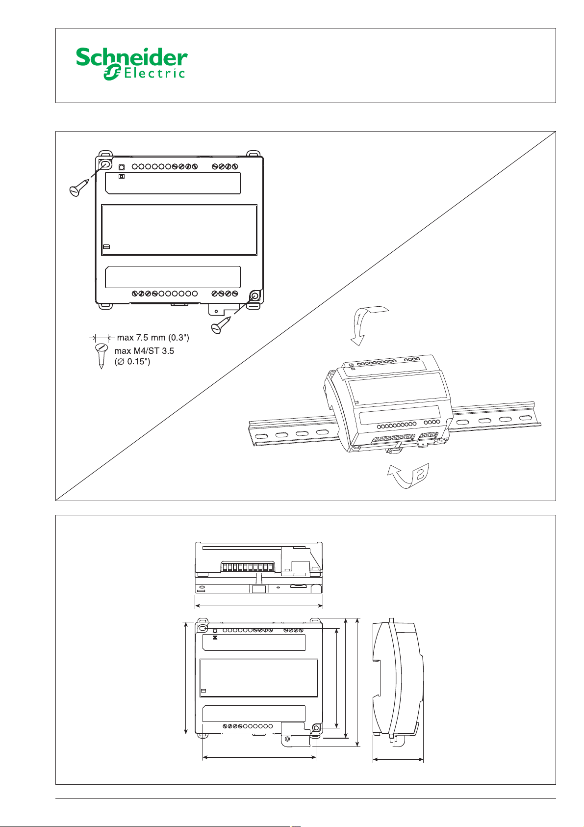
Installation instructions
126 (4.96")
110 (4.33")
112 (4.41")
02-00034-01-en, Nov 2009 1 (4)
98 (3.86")
118 (4.65")
122 (4.80")
50 (2")
English
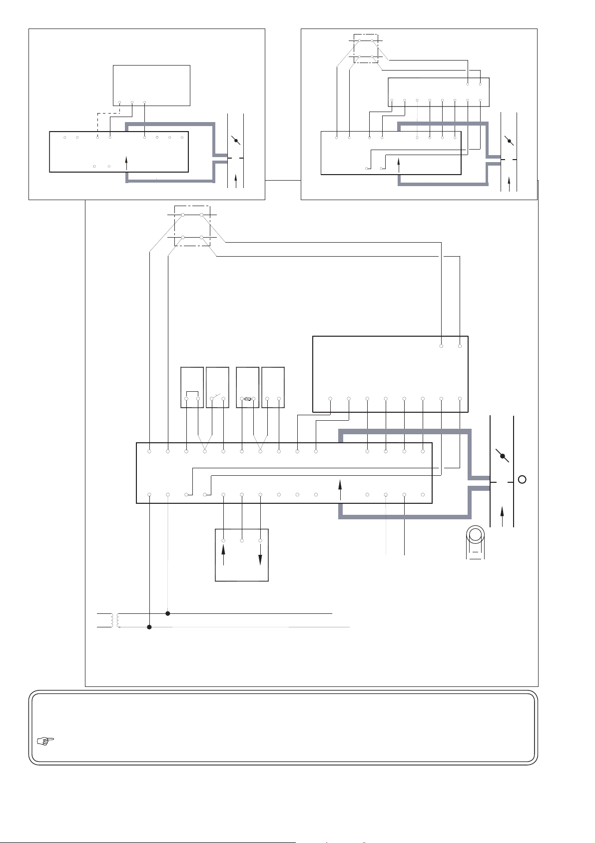
Junction Box
G
OP
17
18
C2
C1
1
2
10
D1
9
X1
11
R1
12
13
B1
14
TAC Xenta
102-ES
Lon Talk"
TP/FT-10
ZS 101-105
7
6
5
3
1
2
G
GO
C1
C2
Wall Module
M
M
G
OP
17
18
C2
C1
1
2
10
D1
9
X1
11
R1
12
13
B1
14
TAC Xenta
102-ES
STR150
Wall Module
M
M
Mode
Data
M
11 1213
Connecting to STR150
Connecting to the ZS series
of wall modules
Lon Talk"
TP/FT-10
1
2
C1
C2
TAC Xenta
102-ES
G
G0
15
16
Junction Box
Window contact
Optional temperature input
Occupancy sensor
GW1 GX1 GQ1
3
X3
OP
17
5
4
X2
M
G
V1
18
19
7
6
B2
M
V2
G
21
20
Application with damper control only
Wall Module
STR101-104
Carbon dioxide sensor
M
LED
+
–
8
U1
V3
22
10
9
M
D1
V4
G
24
23
Mx
16
15
11
25
Pot/Pot+R
Switch
14
13
12
X1
R1
V5
G
26
Therm
11
12
14
13
B1
M
V6
Y1
27
28
21 22
C1
G
C2
OP
2423
2
COM
INC.
DEC.
Network controlled output
Damper actuator
24 VAC
Tubing. Should be connected to controller before being mounted.
Air fl ow sensor, e.g. TAC GV
2 (4) 02-00034-01-en, Nov 2009
Secure the cables to the controller by e.g. clamps. Connect the 24 V AC supply G–G and G0–G0 in all units,
when a common transformer is used. This does not apply to G0 in the wall module. The G0 terminals must be
grounded at the transformer end. Use a maximum 6 A fuse for each controller or each group of control lers. Do
not connect G0 and M. For information on communication cable lengths, please refer to the Xenta Network
Guide, 0-004-7460. Other cable lengths: max 30 m, min 0,7 mm
English
2
(AWG-19).
6
9
(mm)

Junction Box
G
OP
17
18
C2
C1
1
2
10
D1
9
X1
11
R1
12
13
B1
14
TAC Xenta
102-ES
Lon Talk"
TP/FT-10
ZS 101-105
7
6
5
3
1
2
G
GO
C1
C2
Wall Module
M
M
G
OP
17
18
C2
C1
1
2
10
D1
9
X1
11
R1
12
13
B1
14
TAC Xenta
102-ES
STR150
Wall Module
M
M
Mode
Data
M
11 1213
Connecting to STR150
Connecting to the ZS series
of wall modules
Lon Talk"
TP/FT-10
1
2
C1
C2
TAC Xenta
102-ES
G
G0
15
16
Junction Box
Window contact
Optional temperature input
Occupancy sensor
GW1 GX1 GQ1
3
4
X3
OP
17
5
M
G
18
19
INC.
7
6
B2
X2
V1
M
V2
G
21
20
COM
DEC.
Application with damper and reheat control
Wall Module
Carbon dioxide sensor
+
–
8
U1
V3
22
INC.
STR101-104
LED
Mx
16
15
10
9
D1
V4
G
23
24
COM
DEC.
Fan on/off
Pot/Pot+R
Switch
14
13
11
11
12
13
X1
V5
25
M
R1
G
V6
26
27
21 22
C1
C2
OP
G
M
Therm
12
14
B1
Y1
28
2423
6
9
(mm)
Reheat valve actuatorDamper actuator
Network controlled output
22 23 23 24
Thermal actuator
Tubing. Should be connected to controller before being mounted.
24 VAC
Air fl ow sensor, e.g. TAC GV
02-00034-01-en, Nov 2009 3 (4)

Junction Box
G
OP
17
18
C2
C1
1
2
10
D1
9
X1
11
R1
12
13
B1
14
TAC Xenta
102-ES
Lon Talk"
TP/FT-10
ZS 101-105
7
6
5
3
1
2
G
GO
C1
C2
Wall Module
M
M
G
OP
17
18
C2
C1
1
2
10
D1
9
X1
11
R1
12
13
B1
14
TAC Xenta
102-ES
STR150
Wall Module
M
M
Mode
Data
M
11 1213
Connecting to STR150
Lon Talk"
TP/FT-10
Junction Box
Connecting to the ZS series
of wall modules
Application with damper and two stages of reheat control
1
2
C1
C2
TAC Xenta
102-ES
G
G0
15
16
Window contact
Optional temperature input
Occupancy sensor
GW1 GX1 GQ1
3
4
5
X3
M
OP
G
17
18
19
INC.
7
6
B2
X2
V1
M
V2
G
21
20
COM
DEC.
Carbon dioxide sensor
+
–
8
U1
V3
22
INC.
Reheat valve actuatorDamper actuator
22 23
Wall Module
STR101-104
LED
Mx
16
15
10
9
M
D1
V4
G
23
24
Pot/Pot+R
Switch
14
13
11
11
12
13
X1
V5
25
M
R1
G
V6
26
27
21 22
C1
C2
OP
G
M
Therm
12
14
B1
Y1
28
2423
Fan on/off
COM
DEC.
Reheat valve actuator
23 24
6
9
(mm)
Thermal actuator
24 VAC
Tubing. Should be connected to controller before being mounted.
Air fl ow sensor, e.g. TAC GV
4 (4) 02-00034-01-en, Nov 2009
 Loading...