

Page 1
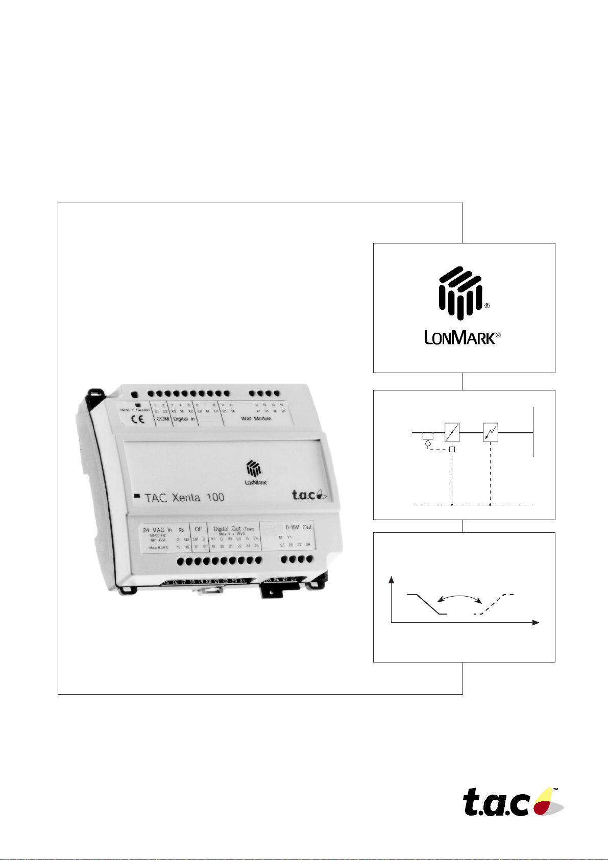
Zone controller
TA C Xenta 102
Handbook
TAC impr oves indoor c limate
and reduces operating costs.
0-004-7516-1 (GB), 1999-08-18
Air flow
Heating
Changeover via
network variable
Cooling
Cooling
demand
Page 2

Page 3

TAC Xenta 102 Handbook Foreword
Foreword
This is the technical handbook for the TAC Xenta 102 controller, a
zone controller for VAV applications in offices and other larger
buildings.
In this second edition of the handbook, sections that were earlier
complicated to the user, have been made clearer, and most of the
content has been reorganized. The trouble-shooting section has been
made into its own chapter, and there are now appendices in the end of
the handbook; one containing setpoint calculating examples, and one
containing a commissioning protocol which can be used together with
chapter 3 when commissioning.
The programs in TAC Xenta 102 now have new versions. For both the
system program and the application program in the controller, the
versions are 1.10. If there is a service replacement in the system, all
variable bindings—if the controller is run on a network—must be
remade when an older or newer version of the controller is fitted. Th is
is because the controller has got a new “Standard Program ID”. There
are also three new network variables.
TAC AB, 1999-08-18
0-004-7516-1 (GB), i (ii)
Page 4

TAC Xenta 102 Handbook Foreword
Copyright © 1999 TAC AB
This document contains information which is the property of TAC and is therefore only available for those using and maintaining TAC’s equipment. Disclosure,
reproduction or use of either the document or the information within for any other purpose are strictly prohibited.
TAC reservs the right to make necessary changes of and additions to the material.
Echelon, Lon, LonWorks, LonTalk, Neuron, 3150, LonMark and the LonMark logo are registered trademarks for Echelon Corporation, USA. TAC Xenta® is a
registered trademark for TAC AB in Sweden and other countries. All other trademarks are the property of their respective owners.
Revisions list
Part number Comment Editor Date
0-004-7516-0 First edition. KRRO 1997-09-11
0-004-7516-1 Second edition. System and application program in a new SUWA 1999-08-18
version 1.10.
ii (ii), 0-004-7516-1 (GB)
TAC AB, 1999-08-18
Page 5

TAC Xenta 102 Handbook Contents
Zone controller TAC Xenta 102
Handbook
Reservations for changes.
Contents
1 Introduction .................................................................................................................. 1:1
1.1 The content of the handbook ............................................................................................................... 1:1
1.2 Documentation .................................................................................................................................... 1:2
1.3 Terminology ........................................................................................................................................ 1:3
2 The zone controller T A C Xenta 102 ............................................................................ 2:1
2.1 General ................................................................................................................................................ 2:1
2.2 Wall modules ....................................................................................................................................... 2:3
2.3 Applications ......................................................................................................................................... 2:4
2.3.1 General ............................................................................................................................................... 2:4
2.3.2 Air flow control only (TAC Xenta 102-B) ................................................................................... ..... 2 : 4
2.3.3 Air flow control with modulating valve reheat (TAC Xenta 102-VF) ................................................ 2:5
2.3.4 Air flow control with modulating valve water reheat and fan (TAC Xenta 102-VF) .................... 2: 5
2.3.5 Air flow control with one stage electric reheat (TAC Xenta 102-EF) ............................................. 2: 6
2.3.6 Air flow control with one stage electric reheat and fan (TAC Xenta 102-EF) ............................... 2: 6
2.3.7 Air flow control with thermo-actuator for radiators (TAC Xenta 102-EF) ................................... 2:7
3 Installation .................................................................................................................... 3:1
3.1 Mechanical installation ....................................................................................................................... 3:1
3.1.1 Fitting.................................................................................................................................................. 3:1
3.2 Electrical installation.......................................................................................................................... 3:3
3.2.1 General ............................................................................................................................................... 3:3
3.2.2 Wiring of TAC Xenta 102-B............................................................................................................. 3 :5
3.2.3 Wiring of TAC Xenta 102-EF ............................................................................................... ........... 3 :6
3.2.4 Wiring of TAC Xenta 102-VF ............................................................................................... ........... 3 : 7
3.3 Commissioning ................................................................................................................................... 3:8
3.3.1 General ............................................................................................................................................... 3 :8
3.3.2 Node status.......................................................................................................................................... 3:8
3.3.3 Configuration parameters (nci’s)...................................................................................................... 3: 9
3.3.4 Network installation ......................................................................................................................... 3:10
3.3.5 Network variable binding ................................................................................................................ 3:10
3.3.6 Function test ..................................................................................................................................... 3:10
4 Configuration parameters ............................................................................................ 4:1
4.1 Basic parameters ................................................................................................................................ 4:2
4.2 Other configuration parameters ......................................................................................................... 4:3
TAC AB, 1999-08-18
0-004-7516-1 (GB), 1 (2)
Page 6

TAC Xenta 102 Handbook Contents
5 Functional description................................................................................................. 5:1
5.1 General ................................................................................................................................................ 5:1
5.2 The controller’s basic functions ......................................................................................................... 5:2
5.2.1 Operation modes ................................................................................................................................ 5:2
5.2.2 Operation mode, manual mode and emergency mode .................................................................... 5:4
5.2.3 Measuring zone temperature ............................................................................................................ 5: 5
5.2.4 Setpoint calculation ........................................................................................................................... 5:6
5.2.6 Control sequence with TAC Xenta 102-B ......................................................................................... 5:8
5.2.5 Control sequence with TAC Xenta 102-EF and 102-VF .................................................................. 5: 8
5.3 More about functions......................................................................................................................... 5:10
5.3.1 Air flow control ................................................................................................................................ 5:10
5.3.2 Heating and fan control ................................................................................................................... 5:11
5.3.3 Air quality control ........................................................................................................................... 5:12
5.3.4 Window contact ................................................................................................................................ 5:13
5.3.5 Occupancy sensor ............................................................................................................................ 5 :13
5.3.6 Minimum value for heating valve (TAC Xenta 102-VF only) ...................................................... 5:14
5.3.7 Alarm ................................................................................................................................................ 5:15
5.3.8 Master/slave operation .................................................................................................................... 5:16
6 Trouble-shooting ........................................................................................................... 6:1
6. 1 General ................................................................................................................................................ 6:1
6.2 Inputs and outputs (nvi/nvo’s).............................................................................................................. 6:2
6.3 Problems and solutions ....................................................................................................................... 6:3
7 T echnical data............................................................................................................... 7:1
7.1 T echnical data...................................................................................................................................... 7:1
7.2 Dimensions.......................................................................................................................................... 7:3
7.2.1 With semi-protection ......................................................................................................................... 7 :3
7.2.2 Without semi-protection .................................................................................................................... 7 :3
8 Communication ............................................................................................................. 8:1
8. 1 General ................................................................................................................................................ 8:1
8.2 Default settings and power on ............................................................................................................. 8:1
8.3 Monitoring network variables, Heartbeat ........................................................................................... 8:2
8.4 Not accepted values.............................................................................................................................. 8:3
8.5 The node object .................................................................................................................................... 8:3
8.5.1 The node object’s inputs (nvi)............................................................................................................ 8 :3
8.5.2 The node object’s outputs (nvo)......................................................................................................... 8 :4
8.5.3 The node object’s configuration parameters (nci) ........................................................................... 8:4
8.6 The controller object ........................................................................................................................... 8:4
8.6.1 The controller object’s inputs (nvi) ...................................................................................... ............. 8 :6
8.6.2 The controller object’s outputs (nvo) ................................................................................................ 8: 7
8.6.3 The controller object’s configuration parameters (nci) .................................................................. 8 :8
Appendix A: Setpoint calculation
Appendix B: Commissioning protocol
Index
Reply form
2 (2), 0-004-7516-1 (GB)
TAC AB, 1999-08-18
Page 7

TAC Xenta 102 Handbook About this handbook
1 Introduction
1.1 The content of the handbook
• Chapter 1 Introduction,
gives an overview over the structure of this handbook,
additional information about the product, and has a short
terminology section.
• Chapter 2 The zone controller TAC Xenta 102,
briefly describes the wall module, the controller’s functions
and control examples of the three different models of TAC
Xenta 102.
• Chapter 3 Installation,
contains instructions on mechanical and electrical
installation of the controller, and instructions on
commissioning and network installation.
• Chapter 4 Configuration parameters,
describes the setting of the zone controller’s configuration
parameters.
• Chapter 5 Functional description,
gives detailed information about the zone controller’s basic
functions, operating modes, and other functions.
• Chapter 6 Trouble-shooting during operation and
commissioning,
contains trouble-shooting measures you can use to find and
remedy possible faults in the system.
• Chapter 7 Technical data,
lists all technical data and dimensions for TAC Xenta 102.
• Chapter 8 Communication,
describes the zone controller’s communication with other
units via the network by means of network variables.
• Appendix A, Setpoint calculation
contains calculating examples for the setpoint calculation in
chapter 5.
• Appendix B
contains a commissioning protocol, which can be used
together with chapter 3 during installation and
commissioning.
TAC AB, 1999-08-18 0-004-7516-1 (GB), 1:1 (4)
Page 8

TAC Xenta 102 Handbook About this handbook
• Index and Reply form,
are in the end of the handbook. Use the index to make your
search for information easier, and the reply form to let us
know whether there is something wrong or unclear in this
handbook.
1.2 Documentation
Enclosed documentation
TAC Xenta 102 is delivered with an installation instruction for
each of the controllers below:
• TAC Xenta 102-B,
Installation instruction, part number 0FL-3857
• TAC Xenta 102-EF,
Installation instruction, part number 0FL-3859
• TAC Xenta 102-VF,
Installation instruction, part number 0FL-3861
Other documentation
There is additional information about TAC Xenta 102 in the
following documents:
• Data sheet for TAC Xenta 102-B,
part number 0-003-1611
• Data sheet f or TAC Xenta 102-EF,
part number 0-003-1617
• Data sheet f or TAC Xenta 102-VF,
part number 0-003-1623
• Data sheet for ZS 101–ZS 105,
part number 0-003-1661. Here the wall modules are described.
• TAC Xenta Network Guide,
part number 0-004-7460. Here you can find additional information on network installation.
• TAC Xenta OP Handbook,
part number 0-004-7506. Here you find information on how to
use TAC Xenta OP together with TAC Xenta 102 and the wall
modules.
• TAC Xenta, Zone System Guidelines
part number 0-004-7637. Here you find information on how a
zone system is built with TAC Xenta components.
• TAC Xenta 102 Handbook,
part number 0-004-7516-0. Here you find information on the
earlier version of the zone controller.
All the above mentioned documents can be found on the internet:
www.tac.se or they can be ordered from the nearest TAC service
point.
1:2 (4), 0-004-7516-1 (GB) TAC AB, 1999-08-18
Page 9

TAC Xenta 102 Handbook About this handbook
1.3 Terminology
In this handbook there are some abbreviations and terms which
are specific for the zone controller’s applications and network
communication. Therefore, the most common terms have been
gathered, together with a short explanation, in the list below.
neuron .................. communication processor with built-in
protocol
node ..................... communication unit on the network
SNVT ................... Standard Network Variable Type
nvixxx .................. variable which gets its value from another
unit on the network
nvoxxx ................. variable which value is sent out to another
unit on the network
ncixxx .................. configuration parameter; variable which gets
its value from another unit on the network
and which keeps it during a power failure
service pin ........... function which can be used during installation
on the network
wink ..................... confirmation that the connection to a controller
via the network is working (a light emitting
diode is lit for appr. 15 seconds)
LNS ...................... LonWork Network Services. System tool for
installation, configuration and maintenance of
LonWorks network
TAC AB, 1999-08-18 0-004-7516-1 (GB), 1:3 (4)
Page 10

TAC Xenta 102 Handbook About this handbook
This page is intentionally left blank.
1:4 (4), 0-004-7516-1 (GB) TAC AB, 1999-08-18
Page 11

TAC Xenta 102 Handbook The zone controller TAC Xenta 102
2 The zone controller TAC Xenta 102
2.1 General
The zone controller TAC Xenta 102 is intended for “Variable
Air Volume” (VAV) applications in offices and other large
buildings. A VAV controller usually controls the temperature in
a given zone by controlling the volume sub-tempered air which
is supplied to the zone.
The controller’ s basic functions
All controller models have a number of built-in functions which
handle the normal control situation. There are four operating
modes to choose from (comfort, economy, bypass, and off) and
five modes to force the controller (only heating allowed, only
cooling allowed, night cooling, auto, and off).
Measuring the zone temperature is made by means of a
permanent thermistor sensor or a temperature node connected
to the network, and setpoint calculation is made according to
special methods.
There is a detailed functional description of all the basic
functions in chapter 5.2.
More about functions
Apart from the controller’s basic functions, there are
additional possibilities to control the climate in the zone. In
section 5.3, these are described in detail, and also which
external functions that may be connected, e.g. window contact
sensor and occupancy sensor.
TAC AB, 1999-08-18 0-004-7516-1 (GB), 2:1 (8)
Page 12
TAC Xenta 102 Handbook The zone controller TAC Xenta 102
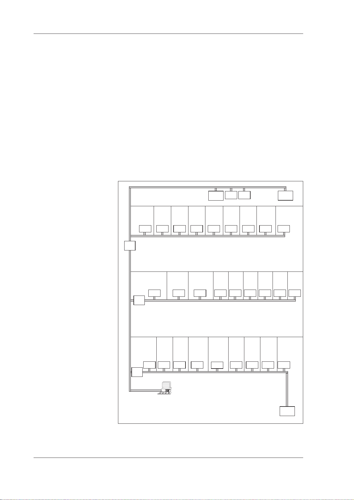
Communication possibilities
The controller can work either as a free-standing unit, without
being connected to a network during operation, or be a part of
a larger system with several other units such as TAC Xenta
300/400 and other zone controllers in the TAC Xenta family
(figure 2.1). A detailed description of how units work together
in a larger zone system, is found in “Guide lines for zone
applications”, part number 0-004-7637.
TAC Vista is an excellent tool for reading variables and as a
configuration tool during commissioning and/or operation.
When TAC Vista is not a part of the system, reading and
configuration of variables can be made from the operating
panel TAC Xenta OP, version 3.11 or later.
4th
floor
3rd
floor
Office 3:1 Office 3:2
Office 3:3 Office 3:4
TAC
Xenta
300
Office 3:5
Analog
Digital
I/O
I/O
Office 3:6 Office 3:7 Office 3:8 Office 3:9
TAC
Xenta
400
2nd
floor
1st
floor
Router
Router
Router
Room
Slave
1:1
101-1VF 101-2VF101-1VF101-1VF101-1VF101-1VF101-1VF101-1VF101-1VF
Master
Room 1:2
Slave
Room 2:2
Slave
102-B 102-B102-B
Room 1:3
Slave
TAC Vista
Room 2:3
Room
1:4
Slave
Slave
Office 2:1
Room 1:5
Master
102-EF102-EF102-EF102-EF102-EF
Office 2:2
Office 1:1
Office 2:3
Office 1:2
Office 2:4 Office 2:5
Office 1:4
Office 1:3
103-A103-A103-A103-A
Office 2:6Room 2:1
101-2VF101-2VF101-2VF101-2VF101-2VF101-2VF
Ground
floor
TAC
Xenta
400
Figure 2.1 Zone controller in a larger system together with TA C Vista
2:2 (8), 0-004-7516-1 (GB) TAC AB, 1999-08-18
Page 13
TAC Xenta 102 Handbook The zone controller TAC Xenta 102
The controller is LONMARK® approved and communicates on a
LONTALK® TP/FT-10 network via a twisted-pair, unpolarized cable.
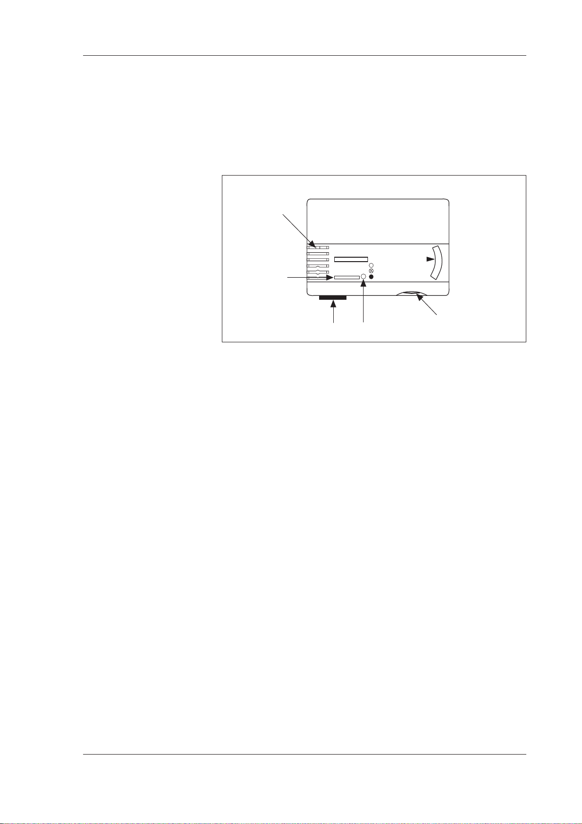
2.2 Wall modules
Locking screw
COMFORT
Bypass key
ECONOMY
OFF
OP connection
Figure 2.2 Wall module in the ZS100 series
Position
indicator
Setpoint knob
In the controlled zone, there is usually a wall module from the
ZS 100 series, which measures the temperature. The wall
modules ZS 101–ZS 105 may very well be used together with
all controller models. On the wall module (figure 2.2) there are
among other things a setpoint knob and a bypass key with
setting possibilities.
The setpoint knob is used to adjust the zone temperature
setpoint with a maximum of ± 5 °C.
The bypass key is used to change the operating mode, and by
pressing the key, an internal timer in the controller, which runs
for two hours, is started. Read more about different operating
modes and ways to force the controller in sections 5.2.1–5.2.2.
On all ZS 100 wall modules, the current operating mode is
indicated by the position indicator (red light emitting diode) as
follows:
· Steady light: Comfort or bypass mode
· Slow flashing: Economy mode
· Fast flashing for appr. 15 s: Answer to “wink” command.
Confirmation that the OP is
connected to the correct
controller
· Off: Other operating modes
There is additional information on the wall modules and how the
temperatures can be adjusted locally in the zone by means of the
keys in “Data sheet for ZS 101–ZS 105”, part number 0-003-
1661.
TAC AB, 1999-08-18 0-004-7516-1 (GB), 2:3 (8)
Page 14
TAC Xenta 102 Handbook The zone controller TAC Xenta 102
2.3 Applications
2.3.1 General
All models have this in common:
• they are intended for use together with a Belimo® VAV-Compact
air flow controller. TAC Xenta 102 sends air flow setpoints to the
VAV-Compact, and reads measured air flow from the air flow controller.
• they have air quality control as an option, which means that the
controller can control the air flow to keep down the carbon dioxide concentration in the zone. However, the function needs a carbon dioxide sensor to be connected to the controller, electronically or via the network.
• a window contact to stop the heating and cooling functions,
should a window be opened, can be connected. An occupancy
sensor can detect the presence of a person in the controlled zone
and change the controller from economy to comfort mode.
The window contact sensor, occupancy sensor, and air quality
control are described in detail in section 5.3.2–5.3.4.
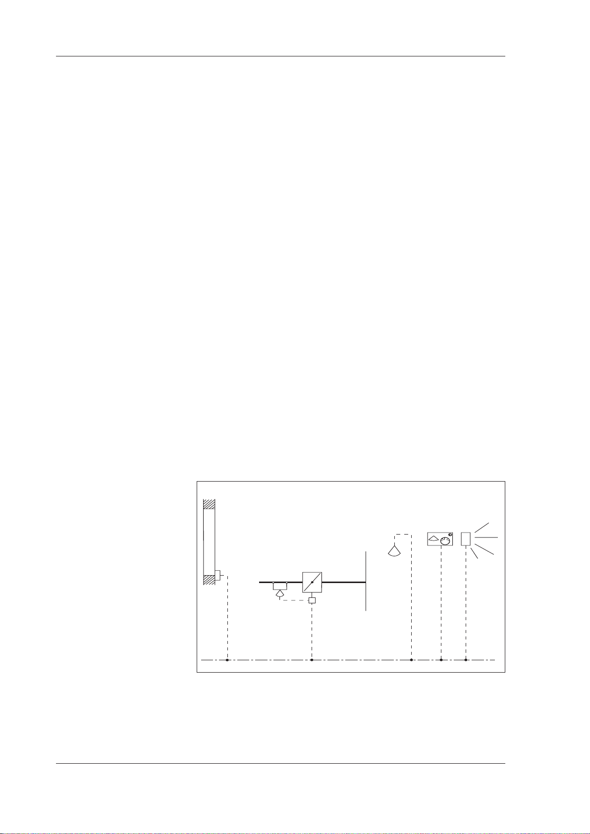
2.3.2 Air flow control only (TAC Xenta 102-B)
The controller controls the zone temperature by means of the
air damper via VAV-Compact. The air flow is minimum and
maximum limited. Usually the controller only uses one cooling
sequence (sub-tempered air in the duct), but it can be changed
to heating (hot air in the duct) given a central command.
Window
contact
Damper and air
flow controller
Wall
sensor
module
Carbon dioxide
Occupancy
sensor
Figure 2.3 Control application for TA C Xenta 102-B
2:4 (8), 0-004-7516-1 (GB) TAC AB, 1999-08-18
Page 15
TAC Xenta 102 Handbook The zone controller TAC Xenta 102
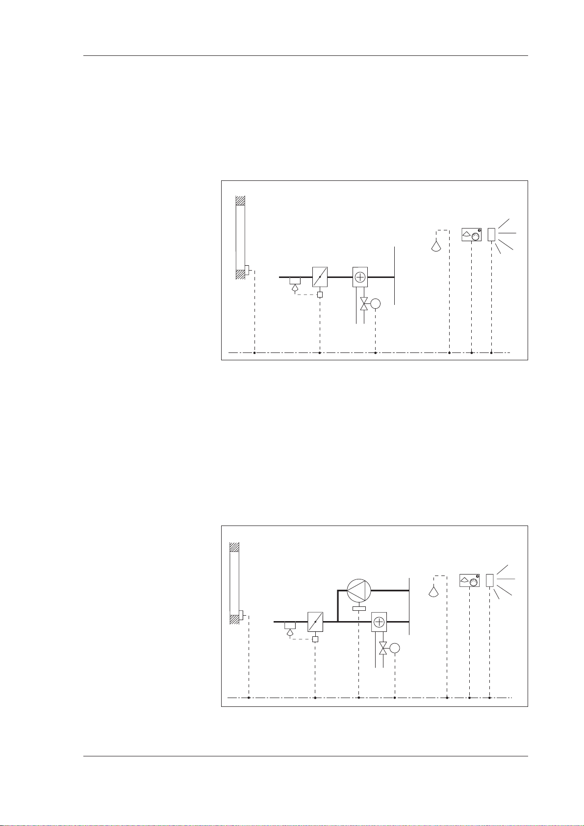
2.3.3 Air flow control with modulating valve water reheat
(TAC Xenta 102-VF)
The controller controls the zone temperature by sequence controlling the air flow controller (VAV-Compact) and the heating coil.
The air flow is minimum and maximum limited. The heating
sequence controls the valve and minimum limits the air flow.
Wall
module
Carbon dioxide
sensor
Occupancy
sensor
Window
contact
Damper and air
flow controller
Heating
water coil
Valve and
actuator
Figure 2.4 Control application for TA C Xenta 102-VF
2.3.4 Air flow control with modulating valve water reheat and fan
(TAC Xenta 102-VF)
The controller controls the zone temperature by sequence controlling the air flow controller (VAV-Compact) and the heating coil.
The airflow is minimum and maximum limited. The heating combines the valve control with the fan to increase the air circulation
through the heating coil.
Window
contact
Damper and air
flow controller
Fan
Heating
water coil
Wall
module
Carbon dioxide
sensor
Occupancy
sensor
Valve and
actuator
Figure 2.5 Control application for T A C Xenta 102-VF
TAC AB, 1999-08-18 0-004-7516-1 (GB), 2:5 (8)
Page 16
TAC Xenta 102 Handbook The zone controller TAC Xenta 102
2.3.5 Air flow control with one stage electric reheat (TAC Xenta
102-EF)
The controller maintains the zone temperature by sequence controlling the air flow controller (VAV-Compact) and the electric
heating coil. The air flow is minimum and maximum limited.
When heating, the controller controls the electric heating coil via a
relay in combination with setting the air flow to its minimum
value.
Window
contact
Damper and air
flow controller
Electric
heating coil
Wall
module
Carbon dioxide
sensor
Occupancy
sensor
Figure 2.6 Control application for T A C Xenta 102-EF
2.3.6 Air flow control with one stage electric reheat and fan (TAC
Xenta 102-EF)
The controller controls the zone temperature by sequence
controlling the air flow controller (VAV-Compact) and the
electric heating coil. The air flow is minimum and maximum
limited. When heating, the controller controls the electric
heating coil by means of a relay in combination with the fan
running to increase the air circulation through the heating coil.
In this application (electric reheat + fan), the minimum limitation
may have separate settings for cooling and heating.
2:6 (8), 0-004-7516-1 (GB) TAC AB, 1999-08-18
Page 17

TAC Xenta 102 Handbook The zone controller TAC Xenta 102
Wall
Fan
module
Carbon dioxide
sensor
Occupany sensor
Window
contact
Damper and air
flow controller
El. heating
coil
Figure 2.7 Control application for T A C Xenta 102-EF
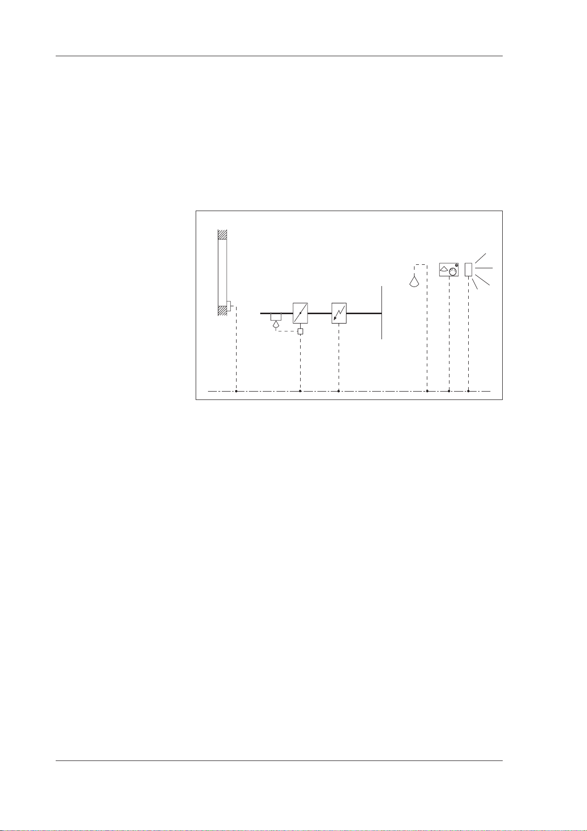
2.3.7 Air flow control with thermo-actuator for radiators
(TAC Xenta 102-EF)
The controller controls the zone temperature by sequence
controlling the air flow controller (VAV-Compact) and the
themo-actuators for radiators. The air flow is minimum and
maximum limited.
Carbon dioxide
Window
contact
Damper and air
flow controller
Valve
Radiators
Figure 2.8 Control application for T A C Xenta 102-EF
Wall module
sensor
Occupancy
sensor
TAC AB, 1999-08-18 0-004-7516-1 (GB), 2:7 (8)
Page 18

TAC Xenta 102 Handbook The zone controller TAC Xenta 102
This page is intentionally left blank.
2:8 (8), 0-004-7516-1 (GB) TAC AB, 1999-08-18
Page 19
TAC Xenta 102 Handbook Installation
3 Installation
3.1 Mechanical installation
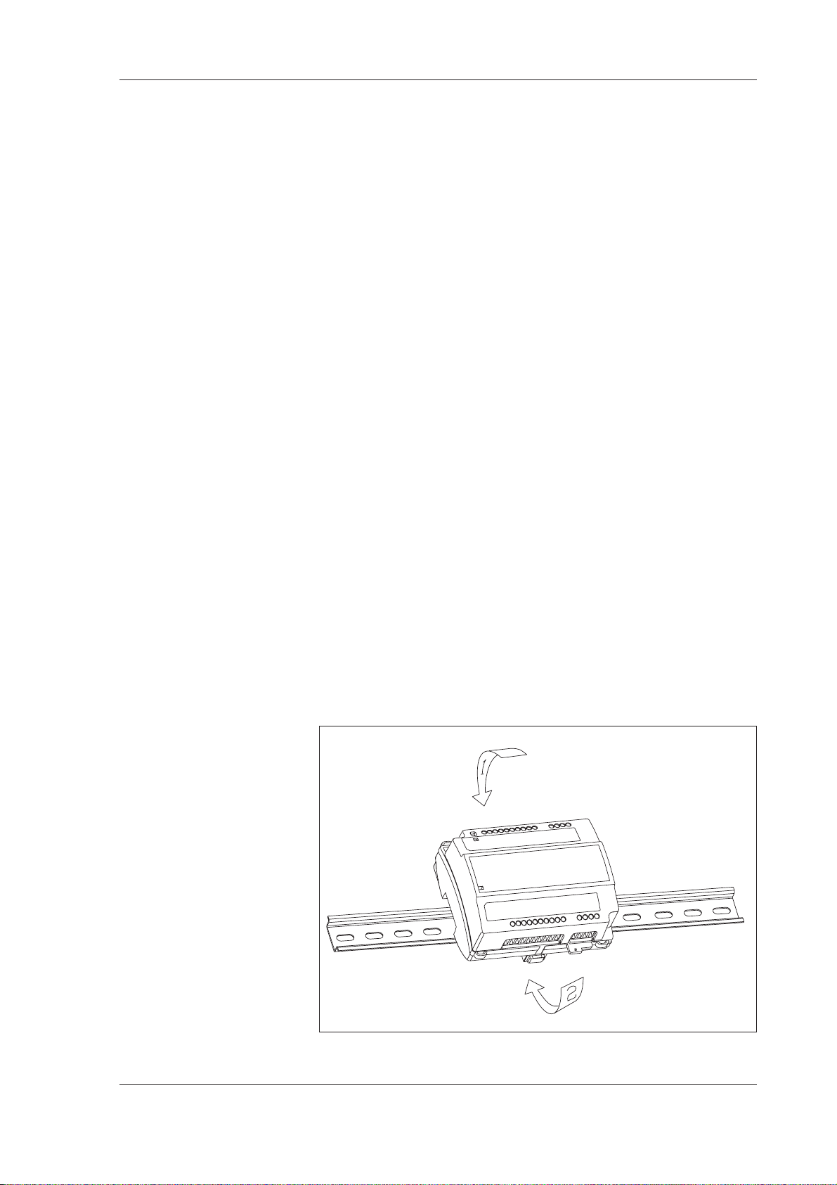
3.1.1 Fitting
TAC Xenta 102 can either be snapped onto a DIN rail (figure
3.1) or fastened with two screws to a level surface (figure 3.2).
On the controllers which controls equipment with 230 V supply,
a semi-protection which covers the relay terminals, should be
fitted (figure 3.3). A semi-protection is delivered together with
these controllers.
T o fasten the contr oller onto a DIN rail:
1. Place the controller on the top of the rail as is shown by arrow 1.
2. Turn the controller downwards until it snaps onto the rail as
is indicated by arrow 2.
3. To remove, place a screwdriver in the lock on the bottom of
the controller and pull down. Then it is possible to lift the
controller diagonally upwards and off the rail.
Figure 3.1 TA C Xenta 102 fastened on a DIN ra il
TAC AB, 1999-08-18 0-004-7516-1 (GB), 3:1 (10)
Page 20

TAC Xenta 102 Handbook Installation
Fastening the controller on a level surface:
Use the two sockets provided for fastening the controller; the
maximum screw size is M4 or ST 3,5. The head of the screw
should not exceed 7,5 mm in diameter.
Figure 3.2 TA C Xenta 102 f astened on a le v el surface
T o fit the semi-protection:
When the cables are secured, the protection is fitted by means of
the enclosed screw.
Figure 3.3 Fitting the semi-protection
3:2 (10), 0-004-7516-1 (GB) TAC AB, 1999-08-18
Page 21

TAC Xenta 102 Handbook Installation
3.2 Electrical installation
3.2.1 General
Warning! All 230 V supply cables must be
!!
1. Each controller or group of controllers must be fitted with
max. 6 A fuses.
2. Secure the cables to the controller by means of clamps or
similar, to limit their mobility.
3. Wire straps or shrinking tubing must prevent loose 230 V
cables from getting in contact with ELV cables—supply or
signal cables—and vice versa.
4. It must be simple to break the power supply for the
controller or for the complete installation.
5. When several Xenta controllers are supplied from a
common transformer, it is important that all G’s are
connected with each other and that all G0’s are connected
with each other. They must not be interchanged. An
important exception
connected with the other G0’s. Instead it should be
connected to the terminal OP on the controller. At the
transformer, G0 should be connected to protective earth.
This is to get an grounding point for interference diversion.
installed by authorised electricians.
: G0 on the wall module should not be
6. Connect the two M terminals to the wall module to get the
specified measuring accuracy for the room temperature.
Safety standard
Transformers supplying the controller must comply to the safety standard EN 60 742 or any other relevant safety standard
for ELV, 24 V AC. When equipment with a power supply of its
own is connected, e.g. an occupancy sensor, this power supply
must also comply with this norm.
Cable lengths
For information on communication cable lengths, see TAC
Xenta Network Guide, part number 0-004-7460. For all other
cables, maximum length is 30 m and min. area is 0,7 mm
2
.
Wall modules ZS 101–ZS 104
It is mainly the wall modules ZS 101–ZS 104 which are intended for use together with TAC Xenta 102. The wall module ZS
105 can also be used, but then the fan switch on this unit is not
used. The wiring diagrams on the following pages show how wiring with ZS 104 should be done, as this is the model that has all
connections.
TAC AB, 1999-08-18 0-004-7516-1 (GB), 3:3 (10)
Page 22

TAC Xenta 102 Handbook Installation
Connection terminals
The designation of the connection terminals can be seen in two
places on the controller: on the edge of the printed circuit board,
and on the label on the front of the controller.
Termin Design. Function Type
no.
1 C1 TP/FT-10 communication channel 2 C2 TP/FT-10 communication channel -
*1
3
4 M Measurement neutral -
*1
5
*1
6
7 M Measurement neutral -
8 Z1 Air flow from VAV-Compact Analogue input
9 D1 LED on wall module Digital output
10 M Measurement neutral 11 X1 Bypass key on wall module Digital input
12 R 1 Setpoint adjustment on wall 10 k
X3 Window contact Digital input
(Closed contact=closed window)
X2 Occupancy sensor Digital input
Z2 Carbon dioxide sensor Analogue input
Ω linear
module potentiometer
13 M Measurement neutral 14 B1 Room temperature sensor Thermistor input
15 G 24 V AC (G) Input
16 G0 24 V AC (G0) Input
*2
17
OP 24 V AC supply for TAC Xenta OP -
18 G 24 V AC supply for TAC Xenta OP 19 V 1 Fan on/off (102-EF and 102-VF)
20 G 24 V AC (G) supply for V1 and V2 Output
21 G0 24 V AC (G0) Output
22 Y 2 Control signal 0–10 V for heating Analogue output
valve (only 102-VF)
23 M Measurement neutral 24 Y1 Control signal, air flow controller Analogue output
25 — Not in use 26 — Not in use 27 K 1 On/off, electric heating coil or
thermo-actuator (only 102-EF),
24 V or 230 V AC Relay
28 K C1 Supply for K1 -
*1
See chapter 4 Configuration parameters
*2
Connected alone to G0 on the wall module. Must not be connected to G0 on
the controller.
3:4 (10), 0-004-7516-1 (GB) TAC AB, 1999-08-18
Page 23
TAC Xenta 102 Handbook Installation
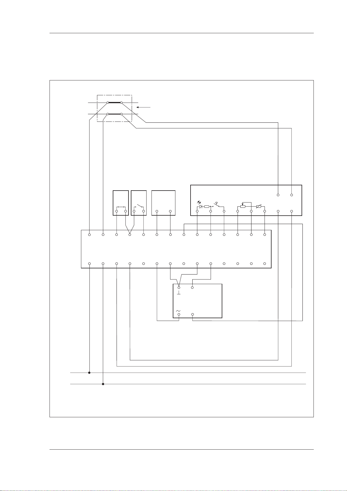
3.2.2 Wiring of TAC Xenta 102-B
Note! Read section 3.2.1 “General” before you connect the
cables according to the wiring diagram in figure 3.4.
LONT
ALK
TP/FT-10
15 16 17 18 19 20 21 22 23 24 25 26 27 28
®
Junction box
Wall module
Window
contact
Occupancy
GW1 GQ1GX1
1234567891011121314
C2 X3 M M MMZ1 X1R1 B1
sensor
X2
+–
Z2
Carbon dioxide
sensor e.g. GKD 2001
V... 24 V AC/DC
10)(9
ZS 104
6
7
D1C1
5
1
3
2
Xenta 102-B
G0
G
OP V1 Y1
GG
G0
M
C1
G
C2
G0
13
Belimo
VAV-Compact
2
5
Air flow controller
with damper
24 V AC (G)
24 V AC (G0)
Figure 3.4 Wiring of TA CXenta 102-B
TAC AB, 1999-08-18 0-004-7516-1 (GB), 3:5 (10)
Page 24

TAC Xenta 102 Handbook Installation
3.2.3 Wiring of TAC Xenta 102-EF
Note! Read section 3.2.1 “General” before you connect the
cables according to the wiring diagram in figure 3.5.
LONTALK
TP/FT-10
15 16 17 18 19 20 21 22 23 24 25 26 27 28
®
Junction box
Wall module
Occupancy
contact
sensor
Carbon dioxide
+–
Z2
X2
sensor, e.g. GKD 2001
V... 24 V AC/DC
10)(9
ZS 104
6
7
D1C1
5
1
3
2
Window
GW1 GQ1GX1
1234567891011121314
C2 X3 M M MMZ1 X1R1 B1
Xenta 102-EF
G0
G
OP V1 Y1
GG
G0 K1 KC1
13
M
Belimo
On/off, fan
VAV-Compact
2
5
Air flow
controller with
Electric
heating
coil
damper
27 28
24 V AC
C1
G
C2
G0
!
230 V AC (L)
230 V AC (N)
CAT III
(IEC 664)
Class II
(EN 61010-1)
Thermal actuator,
e.g. TSE 150 NC/NO
24 V AC (G)
24 V AC (G0)
Figure 3.5 Wiring of TACXenta 102-EF
3:6 (10), 0-004-7516-1 (GB) TAC AB, 1999-08-18
Page 25

TAC Xenta 102 Handbook Installation
3.2.4 Wiring of TAC Xenta 102-VF
Note! Read section 3.2.1 “General” before you connect the
cables according to the wiring diagram in figure 3.6.
LONT
ALK
TP/FT-10
15 16 17 18 19 20 21 22 23 24 25 26 27 28
®
Junction box
Wall module
Window
contact
Närvaro-
givare
Koldioxidgi vare,
t.ex. GKD 2001 V...
24 V A C/DC
GW1 GQ1GX1
10)(9
+–
1234567891011121314
Z2
C2 X3 M M MMZ1 X1R1 B1
X2
6
7
D1C1
5
ZS 104
3
1
2
Xenta 102-VF
G0
G
OP V1 Y2 Y1
GG
G0
M
C1
G
C2
G0
13
G G0 X1/X2M
Belimo
On/off,
fan
EM52L
Actuator, water
heating coil
VAV-Compact
2
5
Air flow
controller with
damper
24 V AC (G)
24 V AC (G0)
Figure 3.6 Wiring of TA C Xenta 102-VF
TAC AB, 1999-08-18 0-004-7516-1 (GB), 3:7 (10)
Page 26

TAC Xenta 102 Handbook Installation
3.3 Commissioning
3.3.1 General
When the mechanical and electrical installation has been made,
you can commission the controller. This means:
· Installing the controller on the network, set node status
and give it an address.
· Set the controller's configuration parameters.
· Bind network variables.
· Test the function.
When it comes to commissioning of complete zone systems,
read the manual “TAC Xenta–Zone Systems Guideline”. Here
you will find a short description of what to do and when to do
it. In short: you could use TAC Xenta OP for setting the basic
parameters. Use a network management tool or TAC Vista for
commissioning the controller on the network and do the rest of
the commissioning.
3.3.2 Node status
When TAC Xenta 100 should be used stand-alone, this is how:
1. Set node status to “Configured” with TAC Xenta OP.
2. Set the basic parameters with TAC Xenta OP.
3. Set the other parameters and variables with TAC Xenta
OP.
You could also use a network management tool for the commissioning.
The node status indicates which mode the controller is in, when
it comes to network configuration and program. The status can
be changed with TAC Vista (version 3.1 or later), network
management tool, or, to some extent, TAC Xenta OP. The
controller can be in these states:
Unconfigured
The controller is in this state when delivered from the factory.
Neither the program nor the network communication are
running. The service light emitting diode is flashing.
The controller cannot work on a network in this state. To do
so, it must be in configured, online state, see below.
You cannot set configuration parameters or network variables
in this state.
3:8 (10), 0-004-7516-1 (GB) TAC AB, 1999-08-18
Page 27

TAC Xenta 102 Handbook Installation
Configured, online
By means of TAC Xenta OP, TAC Vista or a network
management tool, the status can be changed to configured.
Then, both the program and the network communication are
running. The service LED is off. This is the normal state for a
controller in operation.
Now the controller uses the address which it was given by the
tool during configuration. With TAC Xenta OP you cannot,
however, set an address. Therefore all controllers get default
addresses. This means that such a TAC Xenta 100 cannot
work on a network. It can only work stand-alone.
In this state you can set parameters and variables.
Configured, soft online
To get the controller into this state, you need a network
management tool. The controller has a program and a network
configuration, but the program and the communication are at a
standstill. The light emitting diode is off. If the controller is
reset, it will go into configured, online.
Configured, hard online
To get the controller into this state, you need a network
management tool. The controller has a program and a network
configuration, but the program and the communication are at a
standstill. The light emitting diode is off. If the controller is
reset, it will remain in this state.
Without a program and not configured
This states indicates that there is something wrong with the
controller. No program can be detected. The light emitting
diode is lit.
3.3.3 Configuration parameters (nci’s)
TAC Xenta 100 has a number of configuration parameters,
where you can set how the controller should be working. Read
about them in chapter 4. There are also network variables
which controls the controller during operation.
Use the commissioning protocol in Appendix B to write down
your settings at commissioning. In chapter 8, there is
information on all parameters and variables, such as their
index, accepted values, default values. There are detailed
descriptions of the parameters and variables in chapter 4, 5,
and 6.
TAC AB, 1999-08-18 0-004-7516-1 (GB), 3:9 (10)
Page 28

TAC Xenta 102 Handbook Installation
3.3.4 Network installation
For network installation, you need a network management tool
(LNS based or not). Examples of network management tools
are MetraVision and LonMaker for Windows. Here you find
brief information on how this is made. You find more
information in “TAC Xenta, Guidelines for zone applications”.
The installation has two steps:
1. Feed information about the controllers’ unique neuron-ID
into the network management tool’s data base.
2. Let the network management tool install the controller on
the network. The controller will then also get an address.
There are two ways to feed the neuron-ID into the data base:
1. Manually feed the neuron-ID into the network management
tool. To make this easier you can use a bar code reader to
read the detachable ID-neuron label, which you find on all
controllers. It is convenient to gather these labels when you
go around and make the basic configuration, and stick them
to a form, drawing or similar. In the manual “TAC Xenta,
Guidelines for zone applications” there is a form for this
purpose.
2. Use the service pin function. You can only do this when the
controller is connected to the network. On the controller
there is a service pin key in a hole in the upper left corner, at
terminal C1. When you push this, the controller sends out its
neuron-ID. The network management tool can then read the
neuron-ID from the network, to save it in its data base.
3.3.5 Network variable binding
How binding is done depends on which network management
tool is used. To get exact information, you should use the tool’s
documentation. In “TAC Xenta Network manual”, there is
however a description of how network variables are bound
with Metra Vision.
To bind network variables is not an issue when the controller is
used in stand-alone operation.
3.3.6 Function test
You should also make sure that the control works as intended.
In chapter 5 all the controller’s functions are described.
In chapter 6 you find help, should a problem occur.
3:10 (10), 0-004-7516-1 (GB) TAC AB, 1999-08-18
Page 29

TAC Xenta 102 Handbook Configuration parameters
4 Configuration parameters
All communication with the controller is made by means of
network variables. nci’s are used to configure the controller,
nvi’s controls the controller during operation, and nv o’s are
output variables, which the controller sends out on the network.
nci’s are normally set during commissioning, and are not
altered during normal operation (the parameters are stored in
a special memory, and can be changed a maximum of 10 000
times). In chapter 8, there is detailed information on accepted
values and default values for all parameters. All configuration
parameters have default values on delivery.
TAC AB, 1999-08-18 0-004-7516-1 (GB), 4:1 (4)
Page 30

TAC Xenta 102 Handbook Configuration parameters
4.1 Basic parameters
nciAppOptions
These parameters are used to set selectable functions in the controller. The parameter consists of 16 bits, where each bit
represents one functional choice. The bits 10 through 14 are
not used. When you look at nciAppOptions with TAC Xenta OP,
bit 0 is shown to the left.
There is an overview of all the bits’ functions in table 4.1 below.
Table 4.1 The function of different bits in nciAppOptions.
Bit no. Function
Bit 0 0 Occupancy sensor not connected, terminal X2
1 Occupancy sensor connected, terminal X2
Bit 1 0 Energy hold off device (window contact) not connected,
terminal X3
1 Energy hold off device (window contact) connected,
terminal X3
Bit 2 0 Cooling sequence only disabled (only valid for
TAC Xenta 102-B)
1 Cooling sequence only enabled (only valid for
TAC Xenta 102-B)
Bit 3 0 Fan disabled
1 Fan enabled (not valid for TAC Xenta 102-B)
Bit 4 0 Ther mo-actuators normally closed (NC) (only valid for TAC
Xenta 102-EF)
1 Ther mo-actuators normally open (NO) (only valid for TAC
Xenta 102-EF)
Bit 5 0 Air quality control disabled
1 Air quality control enabled
Bit 6 0 Electric heating coil (only valid for TAC Xenta 102-EF)
1 Thermo-actuator for radiators (only valid for
TAC Xenta 102-EF)
Bit 7 0 Slave mode disabled
1 Slave mode enabled
Bit 8 0 Occupancy sensor: closed contact indicates occupancy
1 Occupancy sensor: open contact indicates occupancy
Bit 9 0 If
setpoints for the comfort and economy modes are
calculated using method B (see section 5.2.4).
1 If
setpoints for the comfort and economy modes are
calculated using method A (see section 5.2.4).
nviSetpoint
nviSetpoint
has a valid value, the heating/cooling
has a valid value, the heating/cooling
Bit 15 Reserved for production test. Should not be altered!
Bits 10 through 14 are not used.
4:2 (4), 0-004-7516-1 (GB) TAC AB, 1999-08-18
Page 31

TAC Xenta 102 Handbook Configuration parameters
4.2 Other configuration parameters
The controller’s other configuration parameters are listed below together with a short description. See also chapter 8.
T ab le 4.2 Configuration parameters.
Index Name Description
0
nciLocation
25
nciSetpoints
26
nciSpaceTempDev
27
nciSpaceTempLow
28
nciVAVGain
29
nciVAVItime
30
nciGainHeat
31
nciItimeHeat
32
nciSpaceTempOfst
33
nciMinFlow
34
nciMaxFlow
35
nciMinFlowHeat
36
nciMinFlowStand
37
nciNomFlow
38
nciFlowOfstSlave
Location label
Occupancy temperature setpoints
Max. deviation of zone temperature
Low limit of zone temperqature
Gain fo VAV
Integral time for VAV
Gain for heating controller
Integral time for heating controller
Zone temperature sensor adjustment
Minimum flow
Maximum flow
Minimum flow heating
Minimum flow standby
Nominal flow
Flow offset for slave
39
nciCO2PerVolt
40
nciSpaceCO2Low
41
nciSpaceCO2High
44
nciHeatPrimMin
45
nciInstallType
46
nciSndHrtBt
47
nciRcvHrtBt
Conversion factor ppm CO2 per volt
Space CO2 level for closed damper
Space CO2 level for open damper
Minimum output heating controller
Network configuration source
Send heartbeat
Receive heartbeat
nciLocation
The parameter is used for naming the place where the controller is installed. In the operating panel, this parameter is shown
as the first variable (see section 8.1).
nciSetpoints
The parameter is used for setting the setpoint temperatures for
heating and cooling in comfort and economy mode (see section
5.2.1 and 5.2.4).
nciSpaceTempDev
The parameter is used for setting the maximum allowed deviation of the zone temperature (see section 5.3.7). Default value 2
°C.
nciSpaceTempLow
The parameter is used for setting the lowest allowed zone temperature (see section 5.3.7). Default value 10 °C.
nciV AVGain, nciGainHeat
The parameters give the cooling and heating sequence gain. Default value 25.
TAC AB, 1999-08-18 0-004-7516-1 (GB), 4:3 (4)
Page 32

TAC Xenta 102 Handbook Configuration parameters
nciIV A Vtime, nciItimeHeat
The parameters holds the integral time for the cooling and heating sequence gain. Default value 900 s (15 min).
nciSpaceTempOfst
The parameter is used for adjusting the temperature setpoint.
Default value 0.0 °C.
nciMinFlow, nciMaxFlow
The parameters are used for setting the minimum and maximum flow allowed. Default values 0 l/s and 65535 l/s.
nciMinFlowHeat, nciMinFlowStand
The parameters are used for setting the min. flow allowed at active
heating (only relevant for applications with electrical reheat but
without a fan) and standby respectively. Default value 0 l/s.
nciFlowOfstSlave
The parameter is used for adjusting the flow of the slave controller (see section 5.3.8). Default value 0 l/s.
nciCO2PerVolt
The parameter is used for setting a conversion factor for the
signal from the carbon dioxide sensor to a concentration in
ppm. Default value 200 ppm/V.
nciSpaceCO2Low, nciSpaceCO2High
The parameters are used for setting the air quality control limits (se section 5.3.3). Default value 400 and 1000 ppm.
nciHeatPrimMin (only TAC Xenta 102-VF)
The parameter is used for setting the smallest heating valve
opening allowed (se section 5.3.6). Default value 0%.
nciInstallType
The parameter is used only at free-standing operation and is set
to show that the node should define its own address (see section
8.5.3).
nciSndHrtBt
The parameter is used for determining how often the nvo’s,
which are transmitted continuously on the net, should be sent
(see section 8.3).
nciRcvHrtBt
The parameter is used for determining how long time max. there may be between updating those nvi’s, for which the controller expects continuous updating (see section 8.3).
4:4 (4), 0-004-7516-1 (GB) TAC AB, 1999-08-18
Page 33

TAC Xenta 102 Handbook Functional description
5 Functional description
5.1 General
The controller’s function is determined by its node status
(section 3.3.2), different operation modes (section 5.2.1) and the
ways to force the controller (section 5.2.2) for well-adapted
zone temperatur control. The controller measures the zone
temperature and uses different methods to calculate setpoints.
The air flow is controlled by an external air flow controller.
Apart from the basic functions in chapter 5.2, the controller
has a number of other possibilies to control the climate in the
zone. There are information about these functions in chapter
5.3.
Each section in this chapter is ended with information on which
network variables are used in the current control situation. If
you need details about the network variables’ characteristics,
such as default values and accepted values, you find this in
chapter 8.
TAC AB, 1999-08-18 0-004-7516-1 (GB), 5:1 (16)
Page 34

TAC Xenta 102 Handbook Functional description
5.2 The controller’s basic functions
5.2.1 Operation modes
The controller has four selectable operation modes:
• Comfort
• Economy
• Bypass
• Off
The operation mode is controlled by nviManOccCmd, but is also
influenced by occupancy sensors and the bypass key on the wall
module. The connection between these is shown in table 5.1.
There you also find the controller’s values during stand-alone
operation.
T a ble 5.1 The relation betw een desired operation mode, bypass timer , occupancy sensor and current
operation mode.
Desired op. mode Bypass timer
nviManOccCmd operation mode
Comfort Enabled Without signific. Comfort OC_OCCUPIED
At a standstill Occupancy detect. Comfort OC_OCCUPIED
OC_OCCUPIED No occupancy Economy OC_STANDBY
1
Occupancy sensor2Current
nvoEffectOccup
Economy Enabled Without signific. Bypass OC_BYPASS
OC_STANDBY At a standstill Without signific. Economy OC_STANDBY
Off Enabled Without signific. Bypass OC_BYPASS
OC_UNOCCUPIED At a standstill Without signific. Off OC_UNOCCUPIED
Stand-alone Enabled Occupancy detect. Comfort OC_OCCUPIED
operation No occupancy Bypass OC_BYPASS
At a standstill Occupancy detect. Comfort OC_OCCUPIED
OC_NUL No occupancy Off OC_UNOCCUPIED
1
Activated by the bypass key on the wall module
2
See section 5.3.5 about occupancy sensors
Comfort mode
This is the default mode, when someone is in the zone, and the
controller should give the room a comfortable climate. The
controller is in this mode when nviManOccCmd=OC_OCCUPIED (or OC_NUL after a power down).
The LED on the wall module is lit with a steady red light and
you can use the setpoint knob on the wall module to make a
manual setting and air quality control is enabled. The setpoints
used are found in nciSetpoints (can be modified).
The alarms for the zone temperature deviation, high carbon
dioxide levels, and flow deviation can cut out, but the alarms
for window contact and low zone temperature are blocked.
5:2 (16), 0-004-7516-1 (GB) TAC AB, 1999-08-18
Page 35

TAC Xenta 102 Handbook Functional description
Economy mode
In economy mode, the controller lowers the energy
consumption in the zone by using the heating and cooling
setpoints for economy in nciSetpoints (could be modified). The
controller is in this mode when nviManOccCmd =
OC_STANDBY and the bypass key has not been pressed.
The LED of the wall module flashes slowly. The bypass key can
be used, and also the setpoint knob, if you want to make a
manual setting.
The alarms for the zone temperature deviation, high carbon
dioxide levels, and flow deviation are blocked, but the alarms
for low zone temperature and window contact can cut out.
Bypass mode
The bypass key on the wall module is used if you want to turn
to comfort mode occasionally from economy or off mode.
When someone presses the bypass key on the wall module, the
bypass timer is started and the controller turns to bypass mode.
The bypass timer runs for two hours, and after those two hours
the controller changes operation mode according to table 5.1.
The controller’s bypass mode acts as the comfort mode during
those two hours. Both setpoints and alarms work as in comfort
mode.
Off mode
When the zone is not used for a longer period of time, the controller can be set in off mode. The controller is in this mode
when nviManOccCmd=OC_UNOCCUPIED.
The light emitting diode on the wall module is out. The setpoint
knob is blocked, but the bypass key is not. The alarms for the
zone temperature deviation, high carbon dioxide levels, and
flow deviation are blocked, but the alarms for low zone
temperature and window contact are enabled.
Index Variable name Description
1
nvoEffectOccup
13
nviManOccCmd
nciSetpoints
25
Effective occupancy output
Occupancy scheduler input
Occupancy temperature setpoints
TAC AB, 1999-08-18 0-004-7516-1 (GB), 5:3 (16)
Page 36

TAC Xenta 102 Handbook Functional description
5.2.2 Operation mode, manual mode and emergency mode
TAC Xenta 102 is designed to control both heating and cooling,
and to switch automatically between heating and cooling.
Heating
case
Heating
setpoint
Cooling
setpoint
Cooling
case
Cooling
demand
Figure 5.1 Changeover between heating and cooling cases.
It is possible to force the controller to heating only, cooling
only or night cooling. This is done with nviApplicMode,
according to the table below.
T a ble 5.2 The relation between nviApplicMode and f orcing.
nviApplicMode
HVAC_AUTO Automatic The controller automatically changes over between heating
HVAC_HEAT
HVAC_COOL Cooling only The controller can only cool. The heating setpoint is
Forcing Description
(no forcing) and cooling by controlling with heating and cooling setpoints.
Heating only The controller can only heat. The cooling setpoint is
neglected.
neglected.
HVAC_NIGHT_
PURGE completely open.
HV AC_OFF Off The controller neither cools nor heats.
Night cooling The controller can only cool with night air and the damper is
Manual mode
In this mode, the air flow can be set manually by means of
nviManOverride. The variable has three values, see the table
below. The heating sequence is disabled. The manual mode has
a higher priority than operation and operation mode.
T ab le 5.3 The relation betw een nviManOverride and forcing.
nviManOverride
HVO_OFF Normal operation
HVO_FLOW_VALUE Optional flow is set (l/s)
HVO_PERCENT The damper is set to desired position (%)
5:4 (16), 0-004-7516-1 (GB) TAC AB, 1999-08-18
Description
Page 37

TAC Xenta 102 Handbook Functional description
Emergency mode
In an emergency, the controller can force the damper to
completely opened or closed by means of nviEmergCmd, see the
table below. The heating sequence and the fan are disabled. The
emergency mode has a higher priority than all other modes.
T able 5.4 The relation between nviEmergCmd and f orcing.
nviEmergCmd
EMERG_NORMAL Normal operation
EMERG_PURGE Completely open damper (100%)
EMERG_SHUTDOWN Completely closed damper (0%)
EMERG_PRESSURIZE Completely open damper (100%)
EMERG_DEPRESSURIZE Completely closed damper (0%)
Description
Index Variable name Description
14
nviApplicMode
20
nviManOverride
21
nviEmergCmd
Application mode input
VAV manual override input
Emergency command input
5.2.3 Measuring zone temperature
You can measure the zone temperature either with the wall
module (thermistor sensor) or with a LonTalk temperature
sensor node connected to nviSpaceTemp. If nviSpaceTemp has a
valid value, the controller will use this, otherwise the thermistor
value will be used. The thermistor value (or via the network)
can be adjusted by nciSpaceTempOfst having received a value;
this is added to the thermistor value. The value the controller
uses is also put out on nvoSpaceTemp. If neither value is valid,
nvoSpaceTemp gets the off value. nvoSpaceTemp is sent out
when it has changed at least 0,1°C.
Index Variable name Description
5
nvoSpaceTemp
15
nviSpaceTemp
32
nciSpaceTempOfst
TAC AB, 1999-08-18 0-004-7516-1 (GB), 5:5 (16)
Zone temperature output
Zone temperature input
Zone temperature sensor adjustment
Page 38

TAC Xenta 102 Handbook Functional description
5.2.4 Setpoint calculation
Zone temperature setpoints
nciSetpoints defines temperature setpoints; heating setpoint
comfort mode, cooling setpoint comfort mode, heating setpoint
economy mode, cooling setpoint economy mode.
Table 5.5 Setpoints in nciSetpoints.
Setpoint Min. Max. Default
Cooling setpoint comfort 10 °C 35 °C 23 °C
Heating setpoint comfort 10 °C
Cooling setpoint economy 10 °C 35 °C 25 °C
Heating setpoint economy 10 °C
1
If the cooling setpoint is 10 °C, the heating setpoint is set to 9,5 °C.
1
1
The smallest accepted deviation between the heating and cooling
setpoints is 0,5 °C, and the heating setpoints must be lower than
the cooling setpoints. If the heating setpoints are higher or equal
to the cooling setpoints, the controller resets the heating setpoint
to 0,5 °C lower than the cooling setpoint. Table 5.2 shows accepted values and default values for the four temperature setpoints in
nciSetpoints.
35 °C 21 °C
35 °C 19 °C
The setpoints for comfort and economy mode are basic
setpoints, which can be changed with nviSetpoint,
nviSetPntOffset and the setpoint knob.
Calculation
The current setpoint, nvoEffectSetpt, depends on the current op-
eration, nvoUnitStatus, the desired operation mode, nviApplic-
Mode, and nviSetpoint, nviSetpntOffset, nciAppOptions, nciSetpoints and a possible local setpoint adjustment via the wall
module. Figure 5.2 shows an overview over the relation
between the variables used for setpoint calculation.
nviSetpoint is used to allow the temperature setpoints in comfort
and economy mode to be changed via the network. If there is a
valid value on nviSetpoint, the controller calculates the setpoints
for comfort and economy mode with method A or method B
(the methods are described in Appendix A). The choice of
method is made via nciAppOptions, bit 9. If bit 9=0 method B is
used, and if 9=1 method A is used. If there is no valid value on
nviSetPoint, no recalculation of the temperature setpoints in
nciSetpoints is made.
5:6 (16), 0-004-7516-1 (GB) TAC AB, 1999-08-18
Page 39

TAC Xenta 102 Handbook Functional description
nviSetPntOffset can be r egarded as a setpoint adjustment from a
wall module connected to the network. Its value is added to
setpoints for comfort and economy mode.
In Appendix A there are detailed calculation examples of
setpoint calculation.
Figure 5.6 The relation between variables for the setpoint calculation.
nviSetpntOf fset
Wall module
setpoint knob
nviSetpoint
nciAppOptions bit 9
1
Calculation
according to
method A or B
nciSetpoints
Comf., ool.setp.
2
Comf., heat.setp.
Econ., cool.setp.
if nviSetpoint
has a valid
2
value, otherwise
no recalculation
Addition Addition
Econ., heat. setp.
1
The wall module’s setpoint knob only affects comfort and economy mode.
2
In comfort mode, the setpoints for method A and method B are the same.
Index V ariable name Description
2
4
14
16
17
24
25
nvoUnitStatus
nvoEffectSetpt
nviApplicMode
nviSetpoint
nviSetpntOffset
nciAppOptions
nciSetpoints
Controller
Unit status output
Effective setpoint output
Application mode input
Temperature setpoint input
Setpoint offset input
Application options
Occupancy temperature setpoints
nvoEffectSetpt
TAC AB, 1999-08-18 0-004-7516-1 (GB), 5:7 (16)
Page 40

TAC Xenta 102 Handbook Functional description
5.2.5 Control sequence with TAC Xenta 102-B
The controller changes between the heating and the cooling
sequence by a central command from the network. The heating
sequence is enabled when the variable nviApplicMode has the
value HVAC_HEAT. The cooling sequence is enabled when
nciAppOptions bit 2=1 or when the variable nviApplicMode has
the value HVAC_AUTO, HVAC_COOL or HVAC_NIGHT_-
PURGE. The diagram below shows the heating and the cooling
sequence for TAC Xenta 102-B:
Air flow
max.
Heating
Changeover via
network variable
Cooling
min.
Figure 5.3 Control sequence for TAC Xenta 102-B
Index Variable name Description
14
nviApplicMode
24
nciAppOptions
Application mode input
Application options
Cooling demand
5.2.6 Control sequence with TAC Xenta 102-EF and 102-VF
The air flow (cooling) and an electric heating coil or radiators for
TAC Xenta 102-EF or a heating water coil for TAC Xenta 102-VF
sequence controls the temperature. When the cooling sequence
should be run, the controller calculates an air flow setpoint to
VAV-Compact. Then the air flow controller sets the air flow to the
desired flow.
If the heating sequence should be run, the controller sets an
output to the heating coil, the thermo-actuators or the heating
valve. The air flow is set to a minimum value.
If the controller has a fan as an option, the fan is on when the
heating valve is open in TAC Xenta 102-VF or the electric
heating coil is on in TAC Xenta 102-EF.
The diagrams below illustrates the fan’s function for the
different control sequences.
5:8 (16), 0-004-7516-1 (GB) TAC AB, 1999-08-18
Page 41

TAC Xenta 102 Handbook Functional description
Air flow
100%
max.
min.
Air flow
TAC Xenta 102-EF
100%
max.
min. heat.
min.
Air flow
100%
max.
0%
0%
Heating
Heating
Heating
Fan enabled
Cooling
Cooling
demand
Fan disabled
Cooling
Cooling
demand
Fan enabled
Cooling
min.
0%
Air flow
TAC Xenta 102-VF
100%
max.
Heating
Fan disabled
Cooling
min. heat.
min.
0%
Figure 5.4 Control sequence for TAC Xenta 102-EF and TA C
Xenta 102-VF
Cooling
demand
Cooling
demand
TAC AB, 1999-08-18 0-004-7516-1 (GB), 5:9 (16)
Page 42

TAC Xenta 102 Handbook Functional description
5.3 More about functions
5.3.1 Air flow control
The air flow is controlled by an external air flow controller, for
example Belimo™ VAV-Compact. The air flow controller gets
a setpoint from the VAV controller.
VAV controller
Type: PI
Gain: 0-32,75; default value: 25
I-time: 0-60 minutes; default 15 minutes
Dead band: 0,2 °C
Control interval: 60 s
Air flow setpoints
Either one of the output Y1 (0–10 V), or nvoFlowSetpoint, which
represent the flow in per cent, can be used for the setpoint.
nvoFlowControlPt, is the desired flow in l/s.
Air flow monitoring
TAC Xenta 102 receives the current air flow values from the
air flow controller, by means of input Z1 (0–10 V) or nviBoxFlow.
The controller uses the air flow measurement to monitor deviations. Current air flow can be read by means of the network variable nvoBoxFlow. The above also applies to the slave mode.
Air flow limits
Air flow is limited in comfort and standby mode. The maximum
flow limit nciMaxFlow is used during normal operation. The mini-
mum flow limit nciMinFlowHeat is used when the electric heating
coil is enabled and there is no fan. If radiators are used or the
electric heating coil is on and a fan is used, then nciMinFlow is
used instead. The controller uses the minimum flow limit nciMin-
FlowStand in standby mode.
Nominal air flow
The configuration parameter nciNomFlow defines the nominal
flow through the VAV box. Both the air flow setpoints and
limits depend on the correct value being set in nciNomFlow.
5:10 (16), 0-004-7516-1 (GB) TAC AB, 1999-08-18
Page 43

TAC Xenta 102 Handbook Functional description
Index Variable name Description
2
nvoUnitStatus
6
nvoFlowControlPt
7
nvoBoxFlow
nvoFlowSetpoint
11
22
nviBoxFlow
28
nciVAVGain
29
nciVAVItime
33
nciMinFlow
34
nciMaxFlow
nciMinFlowHeat
35
36
nciMinFlowStand
37
nciNomFlow
Unit status output
Effective flow control output
Box flow output
Flow setpoint output
Box flow input
Gain for VAV
Integral time for VAV
Minimum flow
Maximum flow
Minimum flow heating
Minimum flow standby
Nominal flow
5.3.2 Heating and fan control
TAC Xenta 102-B
TAC Xenta 102-B changes to heating sequence by means of a
command via the network. When there is a heating demand in the
zone, the controller increases the hot air flow in the zone; at a
cooling demand, the controller increases the cold air flow. For this
reason, it is not appropriate to mix Xenta 102-B with other Xenta
102 models in an installation where Xenta 102-B is to control a
heating application, as TAC Xenta 102-EF and VF heat subtempered air instead.
Heating controller (102-VF)
Type: PI
Gain: 0–32,75; default value: 25
I-time: 0–60 minutes; default 15 minutes
Neutral zone: 0,2 °C
Control interval: 60 s
TAC Xenta 102-EF
Heating control in Xenta 102-EF is a one-stage on-off system. The
heating output control, K1, can control either an electric heating
coil or a thermo-actuator. Which model is valid is set by nciApp-
Options. If the electric heating coil is used then the control is
made with a hysteresis of ± 0,25 °C. If the thermal actuators for
radiators are used, the hysteresis is ± 0,1 °C.
When the heating sequence runs and the fan is enabled, both the
coil/radiators and the fan are on when there is a heating demand.
The controller starts the electric heating coil with a 60 second delay. The fan is turned off with a 120 second delay.
TAC AB, 1999-08-18 0-004-7516-1 (GB), 5:11 (16)
Page 44

TAC Xenta 102 Handbook Functional description
TAC Xenta 102-VF
The heating sequence consists of control of the heating coil
combined with a minimum air heating flow, nciMinFlowHeat
(without a fan). A separate PI controller controls the heating
sequence.
Index Variable name Description
2
24
30
31
nvoUnitStatus
nciAppOptions
nciGainHeat
nciItimeHeat
Unit status output
Application options
Gain for heating controller
Integral time for heating controller
5.3.3 Air quality control
In order to maintain a good air quality TAC Xenta 102
controls the supply of air to the controlled zone. If the carbon
dioxide (CO
controller increases the air flow to the controlled zone.
) sensor indicates a high concentration of CO2, the
2
The air flow is proportional to the CO
level and is calculated
2
as a linear function between [nciSpaceCO2Low, nciMinFlow]
and [nciSpaceCO2High, nciMaxFlow].
The air flow is set to the highest value of those coming from the
air quality control and the cooling controller according to
figure 5.5 below.
Air flow
nciMaxFlow
nciMinFlow
CO2 level
nciSpaceCO2Low nciSpaceCO2High
Figure 5.5 Air quality control
The air quality control can be enabled independent of the cooling
controller and is enabled in comfort and bypass mode only.
The carbon dioxide concentration can be measured by means of a
permanent carbon dioxide sensor. The controller transforms the
analogue 0–10 V signal into a concentration in ppm by
muliplying it with the variable nciCO2PerVolt (ppm/volt).
Alternatively, you can use a LonTalk carbon dioxide measuring
node connected to the variable nviSpaceCO2. If nviSpaceCO2
has a valid value, the variable has a higher priority than the
electrically connected sensor.
5:12 (16), 0-004-7516-1 (GB) TAC AB, 1999-08-18
Page 45

TAC Xenta 102 Handbook Functional description
Not to open or close the damper in vain, the CO2 level must differ
by more than ±30 ppm from the latest read value.
nvoSpaceCO2 shows current carbon dioxide level in the zone. If
nviSpaceCO2 has a valid value, the current carbon dioxide level
will be identical to the input.
Current CO2 level is always sent, no matter which options are
set in the variable nciAppOptions. Air quality control is enabled
when bit 5=1 in nciAppOptions.
Index Variable name Description
9
nvoSpaceCO2
18
nviSpaceCO2
24
nciAppOptions
33
nciMinFlow
nciMaxFlow
34
39
nciCO2PerVolt
40
nciSpaceCO2Low
41
nciSpaceCO2High
Zone CO2 sensor output
Zone CO2 input
Application options
Minimum flow
Maximum flow
Conversion factor ppm CO2 per volt
Zone CO2 for closed damper
Zone CO2 for open damper
5.3.4 Window contact
TAC Xenta 102 is designed to be able to limit the energy consumption when a window in the room is open. You can connect
a local sensor directly to the controller, digital input X3, or use
nviEnergyHoldOff. The energy hold off is enabled when either
of these signals indicate an open window. The energy hold off is
made by the controller being set to off mode.
To be able to use a sensor (local or connected to the network),
bit 1 in nciAppOptions must be set to 1.
nvoEnergyHoldOff has the value of the locally connected sensor.
This is true even if bit 1 in nciAppOptions is set to 0.
If the energy hold off has been active for 60 seconds the window
contact alarm cuts out, bit 2 in nvoAlarmstatus (only in economy
and off modes).
Index Variable name Description
3
10
19
24
5.3.5 Occupancy sensor
nvoAlarmstatus
nvoEnergyHoldOff
nviEnergyHoldOff
nciAppOptions
Alarm status output
Energy hold off output
Energy hold off input
Application options
There can be a sensor connected to TAC Xenta 102 to
determine whether someone is in the room or not. If there is no
occupancy sensor connected, the controller supposes that there
is always someone in the room. The controller uses the
information to determine whether the operation mode should be
comfort or economy. When the controller is used stand-alone,
the sensor is used to choose between comfort mode or off mode.
See table 5.1 in chapter 5.2.1.
TAC AB, 1999-08-18 0-004-7516-1 (GB), 5:13 (16)
Page 46

TAC Xenta 102 Handbook Functional description
The sensor can be connected either directly to the controller, input
X2, or via the network, nviOccSensor. To be able to use a directly
connected sensor, bit 0 in nciAppOptions must be set to 1. When
nviOccSensor has received a valid value, this is used, whether
there is a directly connected sensor or not.
Bit 8 in nciAppOptions indicates whether input X2 should mean
normally open (NO) or normally closed (NC). Bit 8=0 means
normally open, Bit 8=1 normally closed.
The directly connected sensor’s value is sent out on the network
in nvoOccSensor. If there is no sensor connected (according to
nciAppOptions), the value OC_NUL is sent out.
There is a 20 minute delay before the operation mode is
changed from comfort to economy in nvoEffectOccup. The
change in nvoOccSensor only takes 250 ms to make other uses
of the occupancy sensor possible (lighting, alarm etc.).
Index Variable name Description
1
nvoEffectOccup
24
nciAppOptions
42
nvoOccSensor
nviOccSensor
43
Effective occupancy output
Application options
Occupancy sensor output
Occupancy sensor input
5.3.6 Minimum value for heating valve (TAC Xenta 102-VF only)
During cold periods, there is often a back draught at the
windows in the room. To avoid this, TAC Xenta 102 offers a
possibility to have a little heat on even if it is not really
necessary to keep the temperature in the room.
This is done by setting a lowest permitted value for the opening
of the heating valve. TAC Xenta 102 makes sure that the
opening never falls below this value. The value is given as a
percentage in nciHeatPrimMin (min. output heating controller).
The function can only be used when using analogue actuators.
The values of the network variables, which shows how TAC
Xenta 102 positions the heating valve nvoUnitStatus
(heat_output_primary), and nvoTerminalLoad which shows the
position of the valve, should not be lower than nciHeatPrimMin.
Index Variable name Description
2
nvoUnitStatus
nvoTerminalLoad
8
44
nciHeatPrimMin
Unit status output
Heating/cooling demand output
Minimum output heating controller
5:14 (16), 0-004-7516-1 (GB) TAC AB, 1999-08-18
Page 47

TAC Xenta 102 Handbook Functional description
5.3.7 Alarm
When TAC Xenta 102 reports alarms to a monitoring system,
this is done with the network variable nvoAlarmStatus. The
variable has 16 bits, which correspond to different alarm
situations.
Alarm conditions for n v oAlarmStatus
Bit no. Alarm Cuts out when... Is reset when...
0 Deviating zone temperature The deviation in zone temp. is The deviation in zone temp. is
larger than
for more than 60 min.
(comfort mode). 0,5 °C).
1 Low zone temperature The zone temp. is lower than the The zone temp. is more than
value in
more than 60 min. (Economy and
off mode).
2 Window contact alarm Energy hold off (window contact) The controller no longer
is enabled for more than 60 s. detects the state.
(Economy and off mode).
nciSpaceTempDev
nciSpaceTempLow
for 2°C above the value in
smaller than the value in
nciSpaceTempDev
nciSpaceTempLow.
(hysteresis
3 High CO
4 Deviation in flow in VAV box The deviation is larger than 10% The controller no longer
10 Not bound
received work variable has been
11 Adaptation of thermistor value Internal writing error in the The controller must be
does not work controller memory. replaced.
12 Bound network variables not Bound network variables have When network variables have
received not been received within set time. been received.
13 Not valid value on input A network variable for input goes The variable gets an accepted
14 No application program No valid application program. The application program is
15 Cannot write to The controller is faulty. The controller must be
EEPROM replaced.
level The CO2 level is 200 ppm higher The controller no longer
2
nvi’s
have not been Power on When the first not bound net-
nciSpaceCO2High
than
than 60 minutes (comfort mode).
nciMaxFlow
of
30 min.
nciRcvHrtBt
outside its accepted value. value.
for more than detects the state.
for more detects the state.
received.
loaded. Contact your nearest
TAC service point.
Index Variable name Description
3
nvoAlarmStatus
26
nciSpaceTempDev
nciSpaceTempLow
27
47
nciRcvHrtBt
TAC AB, 1999-08-18 0-004-7516-1 (GB), 5:15 (16)
Alarm status output
Maximum deviation of zone temperature
Low limit of zone temperature
Receive heartbeat
Page 48

TAC Xenta 102 Handbook Functional description
5.3.8 Master/slave operation
The controller can control a number of slave units, which
makes it possible to control several TAC Xenta 102 controllers
within the same zone. When bit 7 in nciAppOptions is enabled
(=1) the controller works as a slave, otherwise as a master. The
slave and the master controller must be of the same type.
Master
nvoBoxFlow
nvoHeatSlave
nciAppOptions
bit 7 = 0
Inputs
nviBoxFlow
nviHeatSlave
Slave
nciAppOptions
bit 7 = 1
Outputs
and
outputs
Wall
module
Figure 5.6 V ariable bindings between master/sla ve controllers.
The value sent by means of the network variable nvoBoxFlow is
the current flow in the master VAV box. The value which is
sent via the variable nvoHeatSlave is the state for heating, the
percentage and state for a possible fan.
A TAC Xenta 102 working as a slave controller only controls the
heating, the air flow and the fan (if it is selected) according to the
values sent by its master controller on the network. It does not
consider other inputs.
The application mode, which can be read by means of the
variable nvoUnitStatus, is set to off mode for the slave.
The communicating network variables between the master
controller and all the slave controllers are bound according to
figure 5.6.
Index Variab le name Description
7
nvoBoxFlow
12
nvoHeatSlave
22
nviBoxFlow
nviHeatSlave
23
24
nciAppOptions
38
nciFlowOfstSlave
5:16 (16), 0-004-7516-1 (GB) TAC AB, 1999-08-18
Box flow output
Heating control output for slave
Box flow input
Heating control input for slave
Application options
Flow offset for slave
Page 49

TAC Xenta 102 Handbook Trouble-shooting
6 Trouble-shooting
6.1 General
TAC Xenta 102 is normally a very reliable controller. Should
any problems occur, you can use the trouble-shooting tips in
this chapter, preferably when the controller is run on a network, but also when it is used stand-alone. If you need further
help, please contact the nearest TAC service point.
TAC AB, 1999-08-18 0-004-7516-1 (GB), 6:1 (4)
Page 50

TAC Xenta 102 Handbook Trouble-shooting
6.2 Inputs and outputs (nvi/nvo’s)
The most important variables for information on the current
status of the controller during operation, are the nvo’s and the
nvi’s.
With the help of these, you can check the controller’s operation
and redeem any faults or disturbances.
Below you find the nvi’s and the nvo ’s with a short description.
In chapter 8, you find complete information on all variables’ index, variable name, function, accepted values, default values
etc.
T a ble 6.1 Overview over all inputs and outputs.
Index Name Description
nvoEffectOccup
1
2
nvoUnitStatus
nvoAlarmStatus
3
nvoEffectSetpt
4
nvoSpaceTemp
5
6
nvoFlowControlPt
nvoBoxFlow
7
nvoTerminalLoad
8
nvoSpaceCO2
9
nvoEnergyHoldOff
10
Effective occupancy output
Unit status output
Alarm status output (see section 5.3.7)
Effective setpoint output
Zone temperature output
Effective setpoint output (I/s)
VAV box flow output
Heating/cooling demand output. Positive value=cooling, negative value=heating
Zone CO2 sensor output
Energy hold off output, window contact status
nvoFlowSetpoint
11
nvoHeatSlave
12
nviManOccCmd
13
nviApplicMode
14
nviSpaceTemp
15
16
nviSetpoint
17
nviSetpntOffset
nviSpaceCO2
18
nviEnergyHoldOff
19
nviManOverride
20
nviEmergCmd
21
22
nviBoxFlow
nviHeatSlave
23
nvoOccSensor
42
nviOccSensor
43
Effective setpoint for VAV Compact (%)
Heating control output for slave
Occupancy scheduler input
Application mode input (forcing the controller)
Zone temperature input, replaces input B1 at a valid value
Temperature setpoint input, which at a valid value recalculates
Setpoint offset input
Zone CO2 input
Energy hold off input for window contact, determines operation mode together
with input X3
Manual override input
Emergency command input
VAV box flow input
Input heating sequence for slave
Occupancy sensor output, only input X2 is copied, see
information
Occupancy sensor input, determines operation mode together with input X2
nviOccSensor
nciSetpoints
for net
6:2 (4), 0-004-7516-1 (GB) TAC AB, 1999-08-18
Page 51

TAC Xenta 102 Handbook Trouble-shooting
6.3 Problems and solutions
What affects...
Operation?
Operation mode?
(Forcing of
controller)
Check...
• Bypass timer on wall module (X1). If
you have pressed the bypass key, it
takes 2 hours before the time expires.
• Occupancy sensor (X2) or similar network variabl e, nviOccSensor. If the
occupancy sensor has indicated presence, it takes 20 minutes before it is disabled.
• How the content in nvoEffectOccup
can be affected. See section 5.2.1
about operation modes.
• Order via network, nviManOccCmd.
• Chosen settings in nciAppOptions
• Order via net, nviApplicMode
• If a window contact (X3) or similar
network variable, nviEnergyHoldOff,
is enabled.
• Outputs heating, nvoUnitStatus and
nvoTerminalLoad which is affected by
normal control or nciHeatPrimMin.
Control setpoint? • Current operation, nvoEffectOccup
• Current unit status, nvoUnitStatus
• Set basic setpoints, nciSetpoints.
Chosen options in nciAppOptions concerning calculation method A or B
together with nviSetpoint control this.
An invalid value in nviSetpoint gives
the basic setpoints. See section 5.2.4
regarding setpoint calculation.
• nviSetpntOffset and/or the setpoint
knob on the wall module. These give
+/– influence.
Read room
temperature?
• Physical reading (B1) or similar network variable, nviSpaceTemp. A valid
value on the network overrides a physical reading. nciSpaceTempOfst can dis-
place the value.
cont.
TAC AB, 1999-08-18 0-004-7516-1 (GB), 6:3 (4)
Page 52

TAC Xenta 102 Handbook Trouble-shooting
What affects... Check...
Air flow? • Current values in nciMinFlow, nciMax-
Flow, nciMinFlowStand, nciMinFlowHeat, nciNomFlow, nvoFlowControlPt,
nvoFlowSetpoint and nvoBoxFlow.
• Current operation.
• Current operation mode.
That an alarm is set?
The LED on the wall
module?
• Influence from the CO
controller.
2
• Current operation, nvoEffectOccup
• Current values in nciSpaceTempDev
and nciSpaceTempLow.
• If a window is open (window contact).
See also section 5.3.7 on alarms.
• That the controller receives power
also when the LED is out.
• The controller, when the service LED
is lit. This indicates that the controller
does not work propertly and should be
replaced.
• The controller, when the service LED
is lit for 15 seconds and then goes out.
This is not a fault, but an indication
that the controller answers a “wink”
command from the network.
• Current operation.
6:4 (4), 0-004-7516-1 (GB) TAC AB, 1999-08-18
Page 53

TAC Xenta 102 Handbook Technical data
7 Technical data
7.1 Technical data
Part number:
TAC Xenta 102-B ....................................................... 0-073-0531
TAC Xenta 102-EF ..................................................... 0-073-0533
TAC Xenta 102-VF.................................................... 0-073-0535
Power supply............................. 24 V AC –10% +20%, 50–60 Hz
Power consumption:
Controller with TAC Xenta OP.......................................... 4 VA
Power supplies for actuator .................................... max. 12 VA
Digital outputs ........................................................... max. 19 VA
Total, TAC Xenta 102-B.......................................... max. 16 VA
Total, TAC Xenta 102-EF and -VF........................ max. 35 VA
Ambient temperature:
Operation ............................................................... 0 °C – +50 °C
Storage................................................................ –20 °C – +50 °C
Humidity .................................. max. 90% R.H., non-condensating
Housing:
Material................................................................ ABS/PC-plastic
Protection...............................................................................IP 30
Colour............................................................................... grey/red
Dimensions, with semi-protection.................. 127×126×50 mm
–without semi-protection ................................ 122×126×50 mm
Weight................................................................................... 0,4 kg
Inputs for occupancy sensor and window contact, X2-X3:
Voltage open contact.................................... 23 V DC ± 1 V DC
Current closed contact......................................................... 4 mA
Min. pulse width X2 / X3 .......................................... 250 ms/15 s
Temperature sensor input, B1:
Thermistor type .........................................NTC, 1800 Ω at 25 °C
Measuring range..................................................–10 °C – +50 °C
Accuracy ............................................................................. ±0,2 °C
Input, bypass key on wall module, X1:
Min. pulse width .................................................................250 ms
Max. current, LED .............................. 2 mA, for ZS 100 series
TAC AB, 1999-08-18 0-004-7516-1 (GB), 7:1 (4)
Page 54

TAC Xenta 102 Handbook Technical data
Input setpoint control in wall module, R1:
Type ................................................. 10 kΩ linear potentiometer
Adjustment range.................................................. –5 °C – +5 °C
Accuracy ........................................................................... ±0,1 °C
Inputs air flow and carbon dioxide sensor, Z1–Z2:
Measuring range......................................................... 0-10 V DC
Accuracy ...........................................................................±0,05 V
Output air flow, Y1, and output actuator for heating valve, Y2
(only 102-VF):
Output voltage range ................................................ 0–10 V DC
Max. current.......................................................................... 2 mA
Accuracy ............................................................................. ±0,1 V
Output (only 102-EF and 102-VF) for on/off fan control, V1:
Min. output voltage.................................. power supply – 1,5 V
Max. load ............................................................................... 0,8 A
Relay output (only Xenta 102-EF) for electric heating coil or ther-
mo-actuator for radiators, K1 and KC1:
Max. voltage ................................................................. 250 V AC
Max. load .................................................................................. 2 A
Application program:
Cycle time................................................................................. 15 s
LED (light emitting diode) colour:
Power supply ........................................................................ green
Service ....................................................................................... red
Compatibility:
Standard .................................................................. complies with
ONMARK Interoperability Guidelines and
L
LONMARK Functional Profile: VAV Controller
Network protocol .............................................................. LONTALK
Channel ............................................................ TP/FT-10, 78 kbps
Neuron type ............................................................ 3150, 10 MHz
Standards/Norms:
Emission...................................................................... EN 50081-1
Immunity .................................................................... EN 50082-1
Safety........................................................................... EN 61010-1
ETL listing ............................................... UL 3111-1, first version
...................................................CAN/CSA C22.2 No. 1010.1-92
Flammability, integrated materials...............................UL 94 V-0
CE-mark ...................................................complies with demands
Wall modules:
ZS 101 ..........................................................................0-073-0908
ZS 102 .......................................................................... 0-073-0909
ZS 103 .......................................................................... 0-073-0910
ZS 104 ..........................................................................0-073-0911
Accessories:
terminal kit, TAC Xenta 100 ................................... 0-073-0914
Diskett with external interface files (XIF) for
TAC Xenta 100 series ...............................................0-008-5582
7:2 (4), 0-004-7516-1 (GB) TAC AB, 1999-08-18
Page 55

TAC Xenta 102 Handbook Technical data
7.2 Dimensions
7.2.1 With semi-protection
126
98
126,8
110±0,2
118,2
Figure 7.1 Dimensions (mm) for TAC Xenta 102 with semi-protection
7.2.2 Without semi-protection
110±0,2
112±1
126
98
118,2
50
122
112±1
50
Figure 7.2 Dimensions (mm) for TAC Xenta 102 without semi-protection
TAC AB, 1999-08-18 0-004-7516-1 (GB), 7:3 (4)
Page 56

TAC Xenta 102 Handbook Technical data
This page is intentionally left blank.
7:4 (4), 0-004-7516-1 (GB) TAC AB, 1999-08-18
Page 57

TAC Xenta 102 Handbook Communication
8 Communication
8.1 General
The controller consists of two LonMark objects: the node object
(section 8.5) and the controller object (section 8.6). These objects
are monitored by means of the network variables nviRequest and
nvoStatus.
The network variable nciLocation is used when configuring the
basic parameters (section 4.1) to give a detailed description of
the actual place where the controller is fitted. The variable
receives an arbitrary string of signs and dividers as long as the
string is no longer than 30 signs. You can program a certain
location label, e.g.
TAMF.main.floor3.room343/RC40
A LNS based network management tool uses nciLocation when
a data base should be recreated. The monitoring of an already
installed network is made by the LNS tool reading nciLocation,
and then using the information to give the node a sub-system
name and a unit name. The string should therefore consist of a
name and a search path for the sub-system, followed by a slash
and the unit name, i.e.
system.sub-system[.sub-system...]/unit name
8.2 Default settings and power on
For all network variables the following default settings are
valid:
• Number of sent messages per time unit: NONE
• Service type: NOT CONFIRMED if not stated otherwise
• Access check: NO, possible to configure: YES.
• Polled: NO for all nvo and nci, YES for all nvi
(commissioning)
• Synchronized: NO
• Change/update only when the controller is not enabled on
the network; flags = NO
• Restart of TAC Xenta 102 after a change; flags = YES
TAC AB, 1999-08-18 0-004-7516-1 (GB), 8:1 (10)
Page 58

TAC Xenta 102 Handbook Communication
All network variables have the same index as they have in the
menu tree in the operator panel TAC Xenta OP. They represent the
order, in which the y have been declared in the system program, as
the order is important for variables’ self documentatory string. The
variables are of standard type or so called SNVT, and the values
each SNVT can receive, are listed in the tables in this chapter.
Apart from SNVT, there are also standard configuration parameters (SCPT) and parameter types for user configuration (UCPT). If
you want general information about which SNVT/SCPT/UCPT
there are and which values they can receive, the “The SNVT Master List and Programmer's Guide” on the internet address
www.lonmark.org is a good source of information.
At power on, all variables for inputs and outputs (nvi and nvo)
receive their default values after a restart, as the configuration
parameters (nci) keep their earlier set values. After a restart
all nvi’s will send a request to the nvo ’s to which they are bound
(a poll).
8.3 Monitoring network variables, Heartbeat
In TAC Xenta 102 there is a function, called Heartbeat, which can
be configured to monitor input and output variables on the network.
In the overviews in this chapter, you can see whether the variable
is monitored with Heartbeat in the column Hb.
Inputs
Some of the inputs in TAC Xenta 102 are monitored in a way that
the variable must receive values within a certain time for it to be
regarded as valid. If no value is received within this time, the variable will return to its default value. Also, an alarm is enabled, bit
12 in nvoAlarmStatus.
Which outputs are monitored in this way, you find in the list of
network variables in chapter 8.6.1.
The time is set with the variable nciRcvHrtBt. Its default value is
0.0, which means that no monitoring is performed.
Outputs
The bound outputs are normally sent out when they are changed.
Most outputs in TAC Xenta 102 are monitored, so even if the
values are not changed, they are sent out at even intervals.
Which outputs are monitored in this way, you find in the list of
network variables in chapter 8.6.2.
The time is set with the variable nciSndHrtBt. Its normal value
is 0.0, which means that no monitoring is performed.
8:2 (10), 0-004-7516-1 (GB) TAC AB, 1999-08-18
Page 59

TAC Xenta 102 Handbook Communication
8.4 Not accepted values
All nvo’s are limited to their accepted values, and all nvi’s detect
whether the incoming value from the network is within the
accepted limits. If the value is not accepted, the controller
activates bit 13 in the variable for alarm handling, nvoAlarm-
Status. For an nvi, the controller uses the off value, which is
also counted as an accepted value.
8.5 The node object
The variables in the node object (figure 8.1) are separated into
three categories:
• Mandatory (M)
• Optional (O)
• Configuration properties (C)
*
According to LonMark
standardised function
profile for VAV
controllers.
The category “Mandatory” contains all compulsory variables*,
“Optional” contains selectable variables, and ”Configuration
properties” contains the configuration parameters.
Note! The network variables’ indeces are not the same as the
figure in “nv” in the figure.
0 - Node Object
Object Type: 0
nviRequest
nv1
SNVT_obj_request
Mandatory
Network
nvoStatus
nv2
SNVT_obj_status
Variables
nviFileReq
nv5
SNVT_file_req
Optional
Network
nvoFileStat
nv6
SNVT_file_status
Variables
Configuration Properties
nciInstallType SNVT_config_src
Figure 8.1 The node object
8.5.1 The node object’s inputs (nvi)
Index Variable Hb*1SNVT Accepted values Default Description
(Service type) value (self doc. string)
48 nviRequest No SNVT_obj_request 0=RQ_NORMAL RQ_NUL Object request
2=RQ_UPDATE_STATUS (Confirmed) @0|1
5=RQ_REPORT_MASK
50 nviFileReq No SNVT_file_req see “SNVT Master List” FR_NUL File request
(Confirmed) @0|5
*1Hb=Heartbeat
TAC AB, 1999-08-18 0-004-7516-1 (GB), 8:3 (10)
Page 60

TAC Xenta 102 Handbook Communication
8.5.2 The node object’s outputs (nvo)
Index Variable Hb*1SNVT Accepted values Default value Description
(Service type) (self doc. string)
49 nvoStatus No SNVT_obj_status invalid_id (0..1) All = 0 Object status
invalid_request(0..1) (Confirmed) @0|2
51 nvoFileStat Yes SNVT_file_status see ”SNVT Master FS_NUL File status
List” (Confirmed) @0|6
*1 Hb=Heartbeat
8.5.3 The node object’s configuration parameters (nci)
Index Variable Hb*1SNVT Accepted values Default value Description
SCPT/UCPT (self doc. string)
45 nciInstallType No SNVT_config_src 0=CFG_LOCAL 0=CFG_LOCAL Network configu-
SCPT_nwrk_config 1=CFG_EXTERNAL ration source
(25) CFG_NUL &0,,0\x80,25
1
*
Hb=Heartbeat
8.6 The controller object
The variables in the controller object (figure 8.2) are separated
into four categories:
• Mandatory (M)
*
According to LonMark
standardised function
profile for VAV
controllers
• Optional (O)
• Configuration properties (C)
• Manufacturer Defined Section (MDS)
The category “Mandatory” contains all compulsory variables
“Optional” contains selectable variables, ”Configuration properties” contains configuration parameters, and “Manufacturer
Defined Section” is all other variables which make the
controller’s functions possible.
Figure 8.2 is on the next page. Note! The network variables’
indeces are not the same as the figure in “nv” in the figure.
*,
8:4 (10), 0-004-7516-1 (GB) TAC AB, 1999-08-18
Page 61

TAC Xenta 102 Handbook Communication
1 - VAV Controller Object
Object Type: 8010
nviSpaceTemp
nv1
SNVT_temp_p
nviSetpoint
nv2
SNVT_temp_p
nviApplicMode
nv5
SNVT_hvac_mode
nviManOverride
nv6
SNVT_hvac_overid
nviSetpntOffset
nv7
SNVT_temp_p
nviManOccCmd
nv8
SNVT_occupancy
nviEmergCmd
nv9
SNVT_hvac_emerg
nvoBoxFlow
nv10
SNVT_flow
nviEnergyHoldOff
nv11
SNVT_switch
nviSpaceCO2
nv13
SNVT_ppm
nviHeatSlave
nv1
SNVT_switch
Mandatory
Network
nv3
Variables
nv4
Optional
nv16
Network
Variables
nv17
nv18
nv19
nv20
Configuration Properties
nciLocation SNVT_str_asc
nciSetpoints SNVT_temp_setpt
nciMinFlow SNVT_flow
nciMaxFlow SNVT_flow
nciNomFlow SNVT_flow
nciMinFlowHeat SNVT_flow
nciMinFlowStand SNVT_flow
nciVAVGain SNVT_multiplier
nciSndHrtBt SNVT_time_sec
nciRcvHrtBt SNVT_time_sec
Manufacturer Defined Section
nv2
nvoSpaceTemp
SNVT_temp_p
nvoUnitStatus
SNVT_hvac_stat
nvoEffectSetpt
SNVT_temp_p
nvoFlowControlPt
SNVT_flow
nvoBoxFlow
SNVT_flow
nvoTerminalLoad
SNVT_lev_percent
nvoEnergyHoldOff
SNVT_switch
nvoHeatSlave
SNVT_switch
nviOccSensor
nv22
SNVT_occupancy
nciAppOptions SNVT_state
nciGainHeat SNVT_multiplier
nciItimeHeat SNVT_time_sec
nciHeatPrimMin SNVT_lev_percent
nciVAVItime SNVT_time_sec
nciCO2PerVolt SNVT_ppm
nciSpaceCO2Low SNVT_ppm
nciSpaceCO2High SNVT_ppm
nciFlowOfstSlave SNVT_flow_f
nciSpaceTempDev SNVT_temp_p
nciSpaceTempLow SNVT_temp_p
nciSpaceTempOfst SNVT_temp_p
nvoEffectOccup
nv3
SNVT_occupancy
nvoAlarmStatus
nv4
SNVT_state
nvoSpaceCO2
nv5
SNVT_ppm
nvoFlowSetpoint
nv6
SNVT_lev_percent
nvoOccSensor
nv27
SNVT_occupancy
Figure 8.2 The controller object
TAC AB, 1999-08-18 0-004-7516-1 (GB), 8:5 (10)
Page 62

TAC Xenta 102 Handbook Communication
8.6.1 The controller object’s inputs (nvi)
Index Variable Hb*1 SNVT Accepted values Default value Description
(Self doc. string)
13 nviManOccCmd No SNVT_occupancy 0=OC_OCCUPIED OC_NUL Occupancy
1=OC_UNOCCUPIED scheduler input,
3=OC_STANDBY @1|8
other values=OC_NUL
255=OC_NUL
14 nviApplicMode Yes SNVT_hvac_mode 0=HVAC_AUTO HVAC_AUTO Application mode
1=HVAC_HEAT input, @1|5
3=HVAC_COOL
4=NIGHT_PURGE
6=HVAC_OFF;
all other values
interpreted as
HVAC_AUTO
(*2)
15 nviSpaceTemp Yes SNVT_temp_p –10 °C to 50 °C, 327,67 °C
327,67 °C
(*2)
Zone temperaure
input, @1|1
16 nviSetpoint No SNVT_temp_p 10 °C to 35 °C, 327,67 °C(*2)Temperature
327,67 °C
(*2)
setpoint input, @1|2
17 nviSetpntOffset Yes SNVT_temp_p –10 °C to 10 °C 0 °C Setpoint offset
input, @1|7
2
18 nviSpaceCO2 Yes SNVT_ppm 0 to 5000 ppm 65535*
65535*
2
ppm Zone CO2 input,
@1|13
19 nviEnergyHold Ye s SNVT_switch 0=Off, 1=On, Off, 0% Energy hold off
Of f 0% to 100% input. Enabled
at 1=On and ≠ 0%
@1|11
20 nviManOverride No SNVT_hvac 0=HVO_OFF HVO_OFF VAV manual over-
_overid 1=HVO_PERCENT ride input
state 2=HVO_FLOW @1|6
percent other values=HVO_OFF
flow
21 nviEmergCmd No SNVT_hvac 0=EMERG_NORMAL EMERG_ Emergency com-
_emerg 1=EMERG_PURGE NORMAL mand input
2=EMERG_SHUT- @1|9
DOWN 3=EMERG_
PRESSURIZE
4=EMERG_DEPRESSURIZE, other values=
EMERG_NORMAL
22 nviBoxFlow N o SNVT_flow 0 to 65534 0 Box flow input
@1|10
23 nviHeatSlave No SNVT_switch 0=Off, 1=On, 0 % Heating control
0% – 100% input for slave
@1#1
43 nviOccSensor Yes SNVT_occupancy 0=OC_OCCUPIED OC_NUL Occupancy sensor
1=OC_UNOCCOUPIED input
other values=OC_NUL @1#28
1
Hb=Heartbeat
*
2
Off value
*
8:6 (10), 0-004-7516-1 (GB) TAC AB, 1999-08-18
Page 63

TAC Xenta 102 Handbook Communication
8.6.2 The controller object’s outputs (nvo)
Index Variable Hb*1 SNVT Accepted values Default value Description
(Self doc. string)
1 nvoEffectOccup Yes SNVT_occupancy 0=OC_OCCUPIED OC_OCCUPIEDEffective occupancy
1=OC_UNOCCUPIED output
2=OC_BYPASS @1#3
3=OC_STANDBY
255=OC_NUL
2 nvoUnitStatus Yes
SNVT_hvac_status 1=HVAC_HEAT HVAC_HEAT Unit status output
mode 3=HVAC_COOL @1|4
9=HVAC_FAN_ONLY
6=HVAC_OFF
heat_output_primary0% to 100% 163,83%
163,83%(*
heat_output_secondary0% to 100% 163,83%
163,83%(*
cool_output 0% to 100% 163,83%
163,83%(*
econ_output 163,83%
fan_output 0% to 100%, 163,83%
163,83%(*
in_alarm 255
(*2)
(*2)
2)
2)
2)
163,83%(*
2)
255(*
(*2)
(*2)
(*2)
2)
(*2)
2)
3 nvoAlarmStatusNo SNVT_state 16 bits, 0=normal, 00000000 Alarm status
1 = alarm 00000000 output, @1#4
(*2)
4 nvoEffectSetpt Yes SNVT_temp_p 10 °C to 35 °C 327,67 °C
327,67 °C
5 nvoSpaceTemp Yes SNVT_temp_p –10 °C to 50 °C, 327,67 °C(*
327,67 °C
(*2)
Effective setpoint
(*2)
output,@1|16
2)
Zone temperature
output, @1|3
6 nvoFlowControl Yes SNVT_flow 0 to 65534 l/s 0 l/s Effective flow control
65534
(*2)
(*2)
Pt 65534
7 nvoBoxFlow Yes SNVT_flow 0 to 65534 l/s 0 l/s Output air flow in
output, @1|17
VAV box, @1|18
8 nvoTerminal Yes SNVT_lev_percent –163,84% to 163,84% 0% Heat./cool. demand
Load output, @1|19
(*2)
9 nvoSpaceCO2 Yes SNVT_ppm 0 to 5000 65535
65535
(*2)
ppm Zone CO2 sensor
output, @1#5
10 nvoEnergy Yes SNVT_switch 0=Off, 1=On Off, 0% Energy hold off
HoldOff 0% to 100% output
Off, 0% = no delay
@1|20
11 nvoFlowSetpoint Yes SNVT_lev_percent 0% to 100% 0% Flow setpoint output
@1#6
12 nvoHeatSlave N o SNVT_switch 0=Off, 1=On, 0 % Heating control out-
0% to 100% put for slave; @1#2
42 nvoOccSensor Yes SNVT_occupancy 0=OC_OCCUPIED OC_NUL Occupancy sensor
1=OC_UNOCCUPIED output
255=OC_NUL @1#27
1
Hb=Heartbeat
*
2
Off value
*
TAC AB, 1999-08-18 0-004-7516-1 (GB), 8:7 (10)
Page 64

TAC Xenta 102 Handbook Communication
8.6.3 The controller object’s configuration parameters (nci)
Index Variable Hb*1SNVT Accepted values Default values Description
SCPT/UCPT (Self doc. string)
0 nciLocation No SNVT_str_asc 31 ASCII char. All = 0 Location label
SCPT_location (17) &1,1,0\x80,17
24 nciAppOptions No SNVT_state 16 bits, 0–1 00000000 Application options
UCPT (1) 00000000 &1,1,3\x8A,1
25 nciSetpoints No SNVT_temp_setpt 10 °C to 35 °C occ cool = 23 °C Occupancy temp.
SCPTsetPnts (60) stby cool = 25°C setpoints
occ heat = 21°C &1,1,0\x80,60,
stby heat = 19°C 10:35|10:35|10:35|
10:35|10:35|10:35
26 nciSpaceTemp No SNVT_temp_p 0°C to 10°C 2 °C Max. dev. zone temp.
Dev UCPT (16) &1,1,3\x80,16,0:10
27 nciSpaceTemp No SNVT_temp_p 0 °C to 20 °C 10 °C Low limit zone temp.
Lo w UCPT (17) &1,1,3\x80,17,0:20
28 nciVAVGain N o SNVT_multiplier 0 to 32,7675 25 Gain for VAV
SCPTgainVAV(66) &1,1,3\x80,66
29 nciVAVItime No SNVT_time_sec 0 s to 3600 s 900 s Integral time for VAV
UCPT (3) (60 minutes) (15 minutes) &1,1,3\x80,3,0:3600
30 nciGainHeat No SNVT_multiplier 0 to 32,7675 2 5 Gain for heating
UCPT (2) contr., &1,1,3\x80,2
31 nciItimeHeat No SNVT_time_sec 0 s to 3600 s 900 s Integral time for
UCPT (3) (60 minuter) (15 minuter) heating controller
&1,1,3\x80,3,0:3600
32 nciSpaceTemp No SNVT_temp_p -10,0°C to 10,0°C 0,0 °C Zone temp. sensor
Ofst UCPT (20) adjustment, &2,15,3
\x80, 20–10.0:10.0
33 nciMinFlow No SNVT_flow 0 to 65535 l/s 0 l/s Minimum flow
SCPTminFlow(54) &1,1,0\x80,54
34 nciMaxFlow N o SNVT_flow 0 to 65535 l/s 65535 l/s Maximum flow
SCPTmaxFlow(51) &1,1,0\x80,51
35 nciMinFlowHeat No SNVT_flow 0 to 65535 l/s 0 l/s Min. flow heating
SCPTminFlowHeat &1,1,0\x80,55
(55)
36 nciMinFlow No SNVT_flow 0 to 65535 l/s 0 l/s Min. flow standby
Stand SCPTminFlowStby &1,1,0\x80,56
(56)
37 nciNomFlow No SNVT_flow 0 to 65535 l/s 0 l/s Nominal flow
SCPTnomAirFlow &1,1,0\x80,57
(57)
38 nciFlowOfst No SNVT_flow -1500 to 1500 l/s 0 l/s Flow offset for slave
Slave UCPT(15) &1,1,3\x80,15,-1500,
1500
1
Hb=Heartbeat
*
8:8 (10), 0-004-7516-1 (GB) TAC AB, 1999-08-18
Page 65

TAC Xenta 102 Handbook Communication
1
Index Variable Hb*
SNVT Accepted values Default values Description
SCPT/UCPT (Self doc. string)
39 nciCO2PerVolt No SNVT_ppm 0 to 2500 200 ppm Conv. factor ppm
UCPT (9) CO
per volt
2
&1,1,3\80,9, 0:2500
40 nciSpaceCO2 N o SNVT_ppm 0 to 1000 400 ppm Space CO
Lo w UCPT (10) closed damper
level for
2
&1,1,3\80,10, 0:1000
41 nciSpaceCO2 N o SNVT_ppm 0 to 1000 1000 ppm Space CO
High UCPT (11) open damper
level for
2
&1,1,3\80,11, 0:1000
44 nciHeatPrimMin No SNVT_lev_percent 0% to 100% 0% Minimum output
UCPT(23) heating controller
&1,1,3\80,23,0:100
46 nciSndHrtBt Yes SNVT_time_sec 5,0 s to 6553,4 s 0,0 s Send heartbeat
SCPTmaxSend 0,0 s = disabled (disabled) &2,1.2.4.5.6.7.8.9.10.
Time (49) 11.12.42,0\x8A,49
47 nciRcvHrtBt No SNVT_time_sec 0,0 s to 6553,4 s 0,0 s Receive heartbeat
SCPTmaxRcvTime 0,0 s = disabled (disabled) &2,14.15.17.18.19.
(48) 22.23.43,0\x8A,48
*1 Hb=Heartbeat
TAC AB, 1999-08-18 0-004-7516-1 (GB), 8:9 (10)
Page 66

TAC Xenta 102 Handbook Communication
This page is intentionally left blank.
8:10 (10), 0-004-7516-1 (GB) TAC AB, 1999-08-18
Page 67

TAC Xenta 102 Handbook Appendix A: Setpoint calculation
Appendix A: Setpoint calculation
Definitions:
Deadband = Neutral zone
Occupied = Comfort mode
Standby = Economy mode
Unoccupied = Off mode
nviSetPoint = Input temperature setpoint (
nciSetPoints = Six basic setpoints for temperature (
Occupied_cool = Cooling setpoint comfort
Standby_cool = Cooling setpoint economy
Unoccupied_cool = Cooling setpoint off
Occupied_heat = Heating setpoint comfort
Standby_heat = Heating setpoint economy
Unoccupied_heat = Heating setpoint off
Effective = Existing
nviSetpoint
)
nciSetpoints
)
nciSetpoints,
In
you the possibility to move all four setpoints with only one value. The mean value of the comfort setpoints
nciSetpoints
in
my setpoints can be regarded as the basic setpoint for economy mode. The temperature scale for the
setpoints must be as follows:
unoccupied_heat < standby_heat < occupied_heat < occupied_cool < standby_cool < unoccupied_cool.
There are two methods to calculate the setpoints: Method A and Method B.
Method A:
When
nviSetpoint
and heating setpoints are recalculated to be at the same distance from the new, basic setpoint as they
were from the earlier basic setpoint. Therefore, method A removes the existing asymmetry (see the example on the next page).
The controller calculates the different setpoints for heating and cooling in comfort and economy mode,
nviSetpoint
from
lated from the
nciSetpoints
from
deadband_occupied = occupied_cool – occupied_heat
deadband_standby = standby_cool – standby_heat
effective_occupied_cool = nviSetPoint + 0 ,5 (deadband_occupied)
effective_occupied_heat = nviSetPoint – 0, 5 (deadband_occupied)
effective_standby_cool = nviSetPoint + 0, 5 (deadband_standby)
effective_standby_heat = nviSetPoint – 0, 5 (deadband_standby)
the cooling and heating setpoints for comfort and economy mode are set.
can be regarded as the basic setpoint for comfort mode, and the mean value of the econo-
receives a valid setpoint, this value becomes the new, common setpoint. The cooling
, plus or minus half the neutral zone in the comfort and economy modes, which are calcu-
nciSetpoints
.
. The controller takes the differnet heating and cooling setpoints in off mode
nviSetpoint
gives
Method B:
In economy mode you can chose method B to calculate the existing setpoints. In this case, the setpoints’
distance from the existing setpoint, is as far as the distance they were from the old, basic setpoint in
comfort mode. Method B only has influence when the two setpoints from
same value, i.e. when the four setpoints are not placed symmetrically around one value. With Method B
the asymmetry is therefore kept, as the old comfort setpoint is used (see the example on the next page).
The controller calculates the different setpoints for heating an cooling in comfort and economy modes
nciSetpoints
from
occupied_heat setpoint and the occupied_cool setpoint. The controller gets the different heating and cooling setpoints in off mode from
effect_abs_setpoint_ offset = nviSetpoint – (occupied_cool + occupied_heat) /2
effective_occupied_cool = occupied_cool + effect_abs_setpoint_offset
effective_occupied_heat = occupied_heat + effect_abs_setpoint_offset
effective_standby_cool = standby_cool + effect_abs_setpoint_offset
effective_standby_heat = standby_heat + effect_abs_setpoint_offset
TAC AB, 1999-08-18 0-004-7516-1 (GB), App A:1 (2)
. Also, the actual, absolute setpoint deviation is calculated as the mean value of the
nciSetpoints
.
nciSetpoints
do not have the
Page 68

TAC Xenta 102 Handbook Appendix A: Setpoint calculation
The following two examples show which influence
nviSetpoint
has and what Method A and Method B
mean.
Example 1.
1) Assume that you have the following temperatures in
occupied_heat
standby_heat
13
nciSetpoints
occupied_cool
standby_cool
:
2) The basic setpoint for both comfort and economy modes is 22 °C. By means of
moved to 23 °C.
13
nviSetpoint
3) With Method A and Method B you then get the following result:
occupied_heat
standby_heat
13
occupied_cool
standby_cool
3635343332313029282726252423222120191817161514
nviSetpoint
3635343332313029282726252423222120191817161514
3635343332313029282726252423222120191817161514
o
this is
o
o
C
C
C
Example 2.
1) Assume that you have the following temperatures in
occupied_heat
standby_heat
13
nciSetpoints
:
occupied_cool
standby_cool
2) You can allow up to 29 °C before you start cooling in economy mode with
setpoint for comfort is 22 °C and for economy 24 °C.
nviSetpoint
13
3a) With Method A you get the following result:
occupied_heat
standby_heat
13
occupied_cool
standby_cool
3b) With Method B you get the following result:
occupied_heat
occupied_cool
nviSetpoint
3635343332313029282726252423222120191817161514
. The basic
3635343332313029282726252423222120191817161514
3635343332313029282726252423222120191817161514
o
C
o
C
o
C
standby_heat
13
standby_cool
o
3635343332313029282726252423222120191817161514
C
App A:2 (2), 0-004-7516-1 (GB) TAC AB, 1999-08-18
Page 69

TAC Xenta 102 Handbook Appendix B: Commissioning protocol
Appendix B: Commissioning protocol
This protocol can be used when commissioning the VAV controller TAC Xenta 102. Note that the indices are
listed in numerical order, not in the order they are used during commissioning. If you need information on
accepted values, these are found in the tables in chapter 8.
Index Function Variable Default Set Note
value value
0 Location label nciLocation 0
13 Occupancy scheduler input nviManOccCmd OC_NUL
14 Application mode input nviApplicMode 0=Auto
15 Zone temperature input nviSpaceTemp 327,67 °C
16 Temperature setpoint input nviSetPoint 327,67 °C
17 Setpoint offset input nviSetpntOffset 0 °C
18 Zone CO
19 Energy hold off input nviEnergyHoldOff 0=Off, 0%
20 VAV manual override input nviManOverride HVO_OFF
21 Emergency command input nviEmergCmd EMERG_
22 Air flow VAV box input nviBoxFlow 0
23 Heating control input for slave nviHeatSlave 0=Off, 0%
24 Application options nciAppOptions 00000000
25 Occupancy temp. setpoints nciSetpoints
(Cooling setpoint comfort occupied_cool 23 °C)
(Cooling setpoint economy standby_cool 25 °C)
(Heating setpoint comfort occupied_heat 21 °C)
(Heating setpoint economy standby_heat 19 °C)
26 Max. deviation of zone temp. nciSpaceTempDev 2 °C
27 Low limit of zone temperature nciSpaceTempLow 10 °C
28 Gain for VA V nciVAVGain 25
29 Integral time for VAV nciVAVItime 900 s
30 Gain for heating controller nciGainHeat 25
31 Integral time for heat. control. nciItimeHeat 900 seconds
32 Zone temp. sensor adjustment nciSpaceTempOfst 0,0 °C
33 Minimum flow nciMinFlow 0 l/s
34 Maximum flow nciMaxFlow 65535 l/s
35 Minimum flow heating nciMinFlowHeat 0 l/s
36 Minimum flow standby nciMinFlowStand 0 l/s
37 Nominal flow nciNomFlow 0 l/s
38 Flow offset for slave nciFlowOfstSlave 0 l/s
39 Conv. factor ppm CO
40 Space CO
41 Space CO2 level open damper nciSpaceCO2High 1000 ppm
43 Occupancy sensor output nviOccSensor OC_NUL
input nviSpaceCO2 65535 ppm
2
NORMAL
per volt nciCO2PerVolt 200 ppm
level closed damper nciSpaceCO2Low 400 ppm
2
2
cont.
TAC AB, 1999-07-28 0-004-7516-1 (GB), App B:1 (2)
Page 70

TAC Xenta 102 Handbook Appendix B: Commissioning protocol
Index Function Variable Default Set Note
value value
44 Min. output heating controller nciHeatPrimMin 0 %
45 Network configuration source nciInstallType 0=LOCAL
46 Send heartbeat nciSndHrtBt 0,0 seconds
47 Receive heartbeat nciRcvHrtBt 0,0 seconds
48 Object request nviRequest RQ_NUL
50 File request nviFileReq FR_NUL
App B:2 (2), 0-004-7516-1 (GB) TAC AB, 1999-07-28
Page 71

TAC Xenta 102 Handbook Index
Index
A
Air flow control 5:10
Air quality control 5:12
Alarm 5:15
Ambient temperature 7:1
Appendix A: Setpoint calculations
Appendix B: Commissioning
protocol
Applications 2:4
B
Basic parameters 4:2
Bypass key 2:3
Bypass mode 5: 3
C
Cable lengths 3:3
Calculation 5:6
Comfort mode 5:2
Commissioning 3:8
Communication 8:1
Communication possibilities 2:2
Configuration parameters 4:1
Configuration parameters
(nci's) 3:9
Connection terminals 3:4
Controller's basic functions 5:2
Controller object 8:4
D
Data sheets for ZS 101-
ZS 105 2:3
Dimensions 7:3
Documentation 1:2
E
Economy mode 5 :3
Emergency mode 5:4
Electrical installation 3:3
F
Fitting 3:1
Forcing the controller 5:4
Functional description 5:1
G
”Guidelines for zone
systems" 2:2
H
Heartbeat 8:2
Heating and fan control
Xenta 102-EF 5:11
Xenta 102-VF 5:12
Housing 7:1
Humidity 7:1
I
Inputs and outputs (nvi/
nvo's) 6:2
Installation 3:1
L
LNS 1:3
M
Manual mode 5: 4
Master/slave operation 5:16
Measuring zone temperature 5:5
Mechanical installation 3:1
menu tree 8:1
Minimum value for heating
valve 5:14
N
nciAppOptions 4:2
nciRcvHrtBt 4:4
nciSndHrtBt 4:4
Network installation 3:10
Network variable binding 3:10
neuron 1:3
node 1:3
Node object 8:3
Node object inputs (nvi) 8:3
Node object configuration para-
meters (nci) 8:4
Node object outputs (nvo) 8:4
Node status 3:8
Normal settings and power
on 8:1
Not accepted values 8:3
nvoAlarmStatus 5:15
O
Occupancy sensor 5:13
Off mode 5:3
Operation modes 5: 2
Other configuration para-
meters 4:3
Out, light 2:3
P
Power consumption 7:1
Power supply 7:1
Problems and solutions 6:3
R
Red light emitting diode 2:3
S
Safety standard 3:3
Self documentations string 8:1
service pin 1:3
Setpoint calculation 5:6
Setpoints for zone tempera-
ture 5:6
Slow flashing 2:3
Snap the controller onto a DIN
rail 3:1
Stand-alone operation 3:10
Steady light 2:3
T
Technical data 7:1
Terminology 1:3
Trouble-shooting 6:1
V
VAV-controller
air flow limits 5:10
air flow monitoring 5:10
air flow setpoints 5:10
nominal air flow 5:10
W
Wall modules 2:3
Wall modules ZS 101–ZS
104 3:3
Window contact 5:13
wink 1:3
Wiring of TAC Xenta 102-B 3:5
Wiring of TAC Xenta 102-EF 3:6
Wiring of TAC Xenta 102-VF 3:7
With semi-protection 7:3
Without semi-protection 7:3
TAC AB, 1999-08-18 0-004-7516-1 (GB), Reg:1 (2)
Page 72

TAC Xenta 102 Handbook Index
This page is intentionally left blank.
Reg:2 (2), 0-004-7516-1 (GB) TAC AB, 1999-08-18
Page 73

TAC Xenta 102 Handbook Reply form
You can help make this manual even better!
Please help us make our documentation as good as possible. Use this form to let us know of
any errors, unclear descriptions or suggested improvements.
Send the form to: Or e-mail to:
TAC AB helpdesk@tac.se
Helpdesk
Jägershillgatan 18
SE-213 75 MALMÖ
SWEDEN
I have found the following errors and/or unclear descriptions in the “Zone controller Xenta
102 Handbook” (part number 0-004-7516-1 (GB)):
On page: ..................................................................................................................................................
..................................................................................................................................................................
..................................................................................................................................................................
I suggest the following improvements:
On page:..................................................................................................................................................
..................................................................................................................................................................
..................................................................................................................................................................
Name: Company:
TAC AB, 1999-08-18
Page 74

TAC Xenta 102 Handbook Reply form
TAC AB, 1999-08-18
Page 75

TAC Xenta 102 Handbook Reply form
TAC AB, 1999-08-18
Page 76

TAC AB, 1999-08-18
 Loading...