

Page 1

MV Network Management
Easergy
T300
Remote Terminal Unit for distribution networks
User Manual
Page 2

Safety information
Hazard Categories and Special Symbols
Read these instructions carefully and look at the equipment to become familiar with
the device before trying to install, operate, service or maintain it. The following
special messages may appear throughout this bulletin or on the equipment to warn
of potential hazards or to call attention to information that clarifies or simplifies a
procedure.
The addition of either symbol to a “Danger” or “Warning” safety label indicates
that an electrical hazard exists which will result in personal injury if the
instructions are not followed.
This is the safety alert symbol. It is used to alert you to potential personal
injury hazards. Obey all safety messages that follow this symbol to avoid
possible injury or death.
DANGER
DANGER indicates a hazardous situation which, if not avoided,
will result in death or serious injury.
WARNING
WARNING indicates a hazardous situation which, if not avoided,
could result in death or serious injury.
CAUTION
CAUTION indicates a hazardous situation which, if not avoided,
could result in minor or moderate injury.
NOTICE
NOTICE is used to address practices not related to physical injury. The safety alert symbol
shall not be used with this signal word.
Please Note
Electrical equipment should be installed, operated, serviced, and maintained only by
qualified personnel. No responsibility is assumed by Schneider Electric for any
consequences arising out of the use of this material.
A qualified person is one who has skills and knowledge related to the construction,
installation, and operation of electrical equipment and has received safety training to
recognize and avoid the hazards involved.
2
NT00378-EN-03
Page 3

Safety information
Legal information
The Schneider Electric brand and any registered trademarks of Schneider Electric
Industries SAS referred to in this guide are the sole property of Schneider Electric SA and
its subsidiaries. They may not be used for any purpose without the owner's permission,
given in writing. This guide and its content are protected, within the meaning of the French
intellectual property code (Code de la propriété intellectuelle français, referred to hereafter
as "the Code"), under the laws of copyright covering texts, drawings and models, as well
as by trademark law. You agree not to reproduce, other than for your own personal,
noncommercial use as defined in the Code, all or part of this guide on any medium
whatsoever without Schneider Electric’s permission, given in writing. You also agree not
to establish any hypertext links to this guide or its content.
Schneider Electric does not grant any right or license for the personal and noncommercial
use of the guide or its content, except for a non-exclusive license to consult it on an "as is"
basis, at your own risk. All other rights are reserved.
As standards, specifications and designs change from time to time, please ask for
confirmation of the information given in this publication.
FCC Part 15
This equipment has been tested and found to comply with the limits for a Class B digital
device, pursuant to part 15 of the FCC Rules. These limits are designed to provide
reasonable protection against harmful interference in a residential installation. This
equipment generates, uses and can radiate radio frequency energy and, if not installed
and used in accordance with the instruction, may cause harmful interference to radio
communications. However, there is no guarantee that interference will not occur in a
particular installation. If this equipment does cause harmful interference to radio or
television reception which can be determined by turning the equipment off and on, the
user is encouraged to try to correct interference by one or more of the following
measures:
- Reorient or relocate the receiving antenna.
- Increase the separation between the equipment and receiver.
- Connect the equipment into an outlet on circuit different from that to which the
- Consult the dealer or an experienced radio/TV technician for help.
This device complies with FCC RF radiation exposure limits set forth for general
population. This device must be installed to provide a separation distance of at least 20cm
from all persons and must not be co-located or operating in conjunction with any other
antenna or transmitter.
receiver is connected.
NT00378-EN-03
3
Page 4

Easergy T300 Contents
1
GENERAL DESCRIPTION ................................................................................................................................. 6
1.1 FUNCTIONAL DESCRIPTION .................................................................................................................................... 6
1.2 DESCRIPTION OF T300 MODULES .......................................................................................................................... 7
1.2.1 HU250 Module – CPU and Communication Gateway ............................................................................. 7
1.2.2 SC150 Module – Switch Control Unit ...................................................................................................... 7
1.2.3 LV150 Module – Low Voltage measuring Unit ......................................................................................... 8
1.2.4 PS50 Module – Backup Power Supply for severe environments ............................................................ 8
1.2.5 PS25 Module – Backup Power Supply for monitoring and control solutions ........................................... 8
1.3 T300 INTERNAL ARCHITECTURE ............................................................................................................................ 9
1.4 T300 CONFIGURATION PRINCIPLE ....................................................................................................................... 10
1.4.1 Engineering in Easergy Builder ............................................................................................................. 10
1.4.2 Management of RBAC and security policy ............................................................................................ 12
1.5 INITIAL START-UP ............................................................................................................................................... 13
2 CONNECTING TO THE T300 WEB SERVER .................................................................................................. 14
3 OVERVIEW OF THE T300 WEB SERVER ...................................................................................................... 15
3.1 DATA CONSULTATION AND MONITORING PAGES ................................................................................................... 17
3.1.1 Home Page ............................................................................................................................................ 17
3.1.2 Substation Page ..................................................................................................................................... 18
3.1.3 System Page .......................................................................................................................................... 24
3.1.4 Data Pages ............................................................................................................................................ 26
3.2 MEASUREMENTS ................................................................................................................................................. 29
3.2.1 Measurements Pages ............................................................................................................................ 29
3.3 DIAGNOSTIC FILES .............................................................................................................................................. 33
3.3.1 Events Page ........................................................................................................................................... 33
3.3.2 System Page .......................................................................................................................................... 34
3.3.3 Cyber-Security Page .............................................................................................................................. 34
3.4 TRACES .............................................................................................................................................................. 35
3.4.1 Protocol Traces ...................................................................................................................................... 35
3.5 SYSTEM CYBER-SECURITY .................................................................................................................................. 36
3.5.1 Users and roles ...................................................................................................................................... 36
3.5.2 Centralized authentication with RADIUS ............................................................................................... 40
3.6 DEVICE SYNCHRONIZATION ................................................................................................................................. 45
3.6.1 Clock Page ............................................................................................................................................. 45
3.7 IP INTERFACES ................................................................................................................................................... 46
3.7.1 IP Configuration Page ............................................................................................................................ 46
3.8 DIAL-UP MODEM SETTINGS ................................................................................................................................. 51
3.8.1 Modems Configuration Page ................................................................................................................. 51
3.9 UPGRADING THE FIRMWARE ................................................................................................................................ 53
3.9.1 Firmware Page ....................................................................................................................................... 53
3.10 MANAGING THE CONFIGURATION .................................................................................................................... 55
3.10.1 Configuration Page ................................................................................................................................ 55
4 T300 SETTINGS ............................................................................................................................................... 59
4.1 HU250 MODULE SETTINGS ................................................................................................................................. 60
4.1.1 Local I/O ................................................................................................................................................. 60
4.1.2 SCADA Protocols ................................................................................................................................... 64
4.1.3 Master Protocols .................................................................................................................................... 64
4.1.4 Configuring the Physical Ports ............................................................................................................... 65
4.1.5 Synchronization ..................................................................................................................................... 69
4.2 SC150 MODULE SETTINGS ................................................................................................................................. 71
4.2.1 MV Current and Voltage Sensors .......................................................................................................... 72
4.2.2 Switch Control ........................................................................................................................................ 76
4.2.3 Front panel voltage indication ................................................................................................................ 84
4.2.4 MV Voltage Monitoring ........................................................................................................................... 85
4.2.5 Fault current Detection ........................................................................................................................... 88
4.2.6 Fault Current validation and indication ................................................................................................ 104
4.2.7 MV Power Measurement Settings ....................................................................................................... 110
4.2.8 MV Power Quality Settings .................................................................................................................. 111
4.2.9 Automation Settings ............................................................................................................................. 112
4
NT00378-EN-03
Page 5

Easergy T300 Contents
4.3
LV150 MODULE SETTINGS ................................................................................................................................ 114
4.3.1 LV Current and Voltage Sensors ......................................................................................................... 115
4.3.2 Front panel voltage indication .............................................................................................................. 118
4.3.3 LV Voltage Monitoring .......................................................................................................................... 119
4.3.4 Broken Phase Conductor Detection .................................................................................................... 122
4.3.5 LV Power Measurement Settings ........................................................................................................ 124
4.3.6 Power Quality Settings ......................................................................................................................... 125
4.4 PS50 MODULE SETTINGS ................................................................................................................................. 126
4.5 COMMISSIONING TESTS .................................................................................................................................... 127
5 OPERATION ................................................................................................................................................... 128
5.1 INDICATIONS AND ACTIONS ON THE FRONT PANEL ................................................................................................... 128
5.2 TESTING THE LEDS ON THE FRONT PANEL ......................................................................................................... 134
5.3 LOCAL/REMOTE MODE ...................................................................................................................................... 134
5.3.1 Automation Enabled ............................................................................................................................. 135
5.4 SWITCH COMMANDS ......................................................................................................................................... 135
5.5 OTHER COMMANDS .......................................................................................................................................... 135
5.6 BLMON UTILITY ................................................................................................................................................ 136
5.6.1 Accessing BLMon ............................................................................................................... ................. 136
5.6.2 Using BLMon........................................................................................................................................ 137
6 MAINTENANCE .............................................................................................................................................. 138
6.1 DIAGNOSTIC LEDS ON THE FRONT PANEL .......................................................................................................... 139
6.2 POWERING DOWN THE EQUIPMENT .................................................................................................................... 143
6.3 BATTERY MAINTENANCE ................................................................................................................................... 143
6.3.1 Replacing the Battery ........................................................................................................................... 143
6.3.2 Battery Care and Storage .................................................................................................................... 143
6.4 REPLACING THE HU250, SC150 OR LV150 MODULE ......................................................................................... 144
6.4.1 Addressing the SC150 and LV150 Modules ........................................................................................ 144
6.4.2 Checking the Firmware Version ........................................................................................................... 144
6.4.3 Importing a Stored Configuration ......................................................................................................... 144
6.5 REPLACING A BOX MODEM ................................................................................................................................ 145
6.6 REPLACING THE PS50 MODULE ........................................................................................................................ 145
6.6.1 Addressing the PS50 Module .............................................................................................................. 145
6.6.2 Commissioning .................................................................................................................................... 145
6.7 REPLACING THE PS25 MODULE ........................................................................................................................ 145
7 APPENDIX A - GENERAL CHARACTERISTICS .......................................................................................... 146
7.1 HU250 ............................................................................................................................................................ 146
7.2 SC150 ............................................................................................................................................................. 147
7.3 LV150 ............................................................................................................................................................. 148
7.4 HU250, SC150 AND LV150 ............................................................................................................................. 149
7.5 PS50 ............................................................................................................................................................... 150
7.6 PS25 ............................................................................................................................................................... 152
8 ANNEXE B: LIST OF POTENTIAL ISSUE CODES ....................................................................................... 153
8.1 SC150 POTENTIAL ISSUE CODES ON SWITCH CONTROL ....................................................................................... 153
9 APPENDIX C: GLOSSARY ............................................................................................................................ 154
9.1 ABBREVIATIONS AND DEFINITIONS ..................................................................................................................... 154
10 APPENDIX D: INVERSE DEFINITE MINIMUM TIME (IDMT) CURVES ........................................................ 157
NT00378-EN-03
5
Page 6

Presentation General description
DANGER
HAZARD OF ELECTRIC SHOCK, EXPLOSION, OR
ARC FL ASH
Wear your personal protective equipment (PPE) and
comply with the safe electrical work practices. See
NFPA 70E in the USA or applicable local standards.
This unit must be installed and serviced only by
qualified electrical personnel.
Turn off all power supplying this unit before working
on or inside the unit.
Always use a properly rated voltage sensing device to
confirm that the power is off.
A live current transformer secondary circuit must not
be opened without turning off the primary side of the
transformer and short-circuiting transformer secondary
circuit first.
Replace all devices, doors and covers before turning
on power to this unit.
Failure to follow these instructions will result in
death or serious injury.
WARNING
LOSS OF CONTROL
The designer of any control scheme must consider the
potential failure modes of control paths and, for certain
critical control functions, provide a means to achieve a
safe state during and after a path failure. Example:
Emergency Stop.
Separate or redundant control paths must be provided
for critical control functions.
System control paths may include communication
links. Consideration must be given to the implications
of anticipated transmission delays or failures of the
link.
Failure to follow these instructions can result in
death or serious injury.
1 General description
1.1 Functional description
Easergy T300 features a modular architecture designed for applications in MV
network substations.
The T300 offers the following functions:
Management of the open/close motor mechanism on MV switchgear,
compatible with any MV switch
Detection of ammetric and directional fault currents on the MV
network: operational on any neutral system with or without the presence of
distributed power and including fault current algorithms based on the
following international standards:
o Phase overcurrent and ground fault detection (ANSI 50/51,
ANSI 50N/51N)
o Directional overcurrent and ground fault detection (ANSI 67/67N)
Two fault current detection methods are used:
o Definite time (DT) curve
o Inverse definite minimum time (IDMT) curve
MV network voltage and current monitoring, for the following functions:
MV current measurement using standard current sensors, compatible
MV voltage measurement using the following voltage sensors:
MV power measurement according to standard IEC61557-12
Quality
LV network voltage monitoring, for the following functions:
LV current measurement using standard current sensors, compatible
LV voltage measurement via a Voltage adapter measuring directly the
LV power measurement according to IEC 61557-12.
Quality of the LV power supply delivered according to the principles of
Transformer monitoring:
Monitoring, remote indication, and local display of T300 and
Integrated automation functions in the SC150 modules (Sectionalizer)
o Undervoltage detection (ANSI 27)
o Overvoltage detection (ANSI 59)
o Neutral overvoltage detection (ANSI 59N)
o Voltage broken conductor detection (ANSI 47)
o Undercurrent detection (ANSI 37)
with standard IEC 61869-2, according to three possible configurations:
o 3 phase CTs
o 1 core balance CT
o 3 phase CTs + 1 core balance CT
o LPVT (low power voltage transformer) conforming to standard
IEC 60044-7
o Standard MV/LV VTs with secondary from 57 Vac to 220 Vac
conforming to IEC 61869-3 (requires a VT adapter)
o VPIS (voltage presence indicating system) with voltage
output (VPIS-VO)
o VDS (voltage detecting system) indicator with voltage output
(standard IEC 61243-5)
o PPACS external capacitive divider mounted at the head of the
MV cable
of the MV power supply delivered, according to the principles of
IEC 61000-4-30 class S (up to harmonic 15), for T300 RTUs equipped
with LPVT and VT sensors
o Undervoltage detection (ANSI 27)
o Overvoltage detection (ANSI 59)
o Neutral overvoltage detection (ANSI 59N)
o Voltage broken conductor detection (ANSI 47)
with IEC61869-2, according to two possible configurations:
o 3 phase CTs
o 3 phase cores + 1 neutral measuring sensor
voltage on the LV network.
IEC 61000-4-30 class S (up to harmonic 15).
o Temperature monitoring with threshold alarm
o Measurement of current peaks
substation data
6
NT00378-EN-03
Page 7

Presentation General description
Easergy HU250 module
Easergy SC150 module
Recording of time- and date-stamped events in logs (SOE)
Battery-backed power supply with several hours independent operation
in the event of an AC line outage
Local or remote communication over 1 or more communication
channels: local communication with auxiliary equipment; remote
communication with the remote control center (SCADA system).
The following modems are managed on the communication ports:
o 2G/3G and 3G/4G (standard EU and US versions)
o RS232/RS485
Communication protocols for communicating with the control center or
with other devices:
o IEC 60870-5-101 slave and IEC 60870-5-104 master and slave
o DNP3 master and slave
o Modbus master and slave
o IEC 61850 client and server.
Device time synchronization, can be set:
o Via the communication protocol
o Via the SNTP server
IEC 61131-3 PLC (IsaGRAF®) including text and graphics editors for
executing specific custom applications in the following programming
languages:
o SFC: Sequential Function Chart
o FBD: Function Block Diagram
o LD: Ladder Diagram
o ST: Structured Text
o IL: Instruction List
1.2 Description of T300 Modules
Easergy T300 comprises several communicating modules.
1.2.1 HU250 Module – CPU and Communication
Gateway
The T300 HU250 module manages the following functions:
User database and access rights administration
Remote communication with the control center (SCADA system) via the
protocols (IEC 60870-5-101/IEC 60870-5-104/IEC 61850) and the secure
protocol (DNP3)
Local communication with other substations (inter-device communication)
Flexible communication media (Ethernet, 2G, 3G, 4G)
Communication gateway for the T300 modules
LAN communication for third-party devices (IED) in master protocols
(Modbus, IEC 60870-5-104, IEC 61850, DNP3)
Access to local and remote configuration for all T300 modules
Web server with local and remote access
Integrated automation function with execution of programmable logic
control
Remote/local operation of global functions, enabling/disabling of PLC
function
For more information regarding installing, connection, and use of HU250
module, refer to the HU250 Installation Guide (ref: NHA77925-xx).
1.2.2 SC150 Module – Switch Control Unit
The T300 SC150 module manages the following functions:
Control and monitoring of all switch types
Detection of ammetric and directional fault currents:
o Detection of Ammetric phase overcurrent and ground fault
o Detection of Directional phase overcurrent and ground fault
Detection of broken phase conductor
Current measurements using standard current transformers
MV Voltage measurements using different types of sensor: LPVT, VT,
VDS, VPIS, and external capacitive divider installed on the MV cables
MV Power measurement in accordance with standard IEC 61557-12
MV Power quality according to the principles of IEC 61000-4-30 class S
(up to harmonic 15)
Special integrated automation function: sectionalizer
For more information regarding installing, connection, and use of SC150
module, refer to the SC150 Installation Guide (ref: NHA91857-xx).
NT00378-EN-03
7
Page 8

Presentation General description
1.2.3 LV150 Module – Low Voltage measuring Unit
The T300 LV150 module manages the following functions:
Current measurements using standard current transformers
LV Voltage measurements using Voltage adaptor
LV Power measurement in accordance with standard IEC 61557-12
LV Power quality according to the principles of IEC 61000-4-30 class S
(up to harmonic 15)
Detection of broken phase conductor
For more information regarding installing, connection, and use of LV150
module, refer to the LV150 Installation Guide (ref: NHA92575-xx).
Easergy LV150 module
Easergy PS50 module
Easergy PS25 module
1.2.4 PS50 Module – Backup Power Supply for
severe environments
The PS50 is the default power supply for the T300. It supplies power to the
system and allows, through a battery-backup power supply, continuity of
operation for the equipment listed below in the event of a power outage:
Motor mechanism for the MV switches and circuit breakers
Transmission interfaces (radio, modem, etc.)
T300 electronic modules
Third-party devices, such as protection relays, fault current passage
indicators, and other electronic equipment installed in the MV substation
The PS50 module can communicate on an RS485 Modbus link with the HU250
module to exchange information managed by the PS50 power supply. This
communication also makes it possible to set the PS50 module from the T300
web server.
For more information regarding installing, connection, and use of PS50 module,
refer to the PS50 Installation Guide (ref: NT00375-xx).
1.2.5 PS25 Module – Backup Power Supply for
monitoring and control solutions
The PS25 module is the dedicated power supply for monitoring and control
solutions of MV electrical networks using a T300. The PS25 module provides a
single 12 V or 24 V supply voltage to the system (depending on the model). It
has a battery-backup power supply which in the event of a power outage
enables operation of:
T300 electronic modules
Measurement and monitoring functions
The PS25 module does not include any communication. It operates
autonomously. Set up is done directly on the product.
For more information regarding installing, connection, and use of PS25 module,
refer to the PS25 Installation Guide (ref: NT00376-xx).
8
NT00378-EN-03
Page 9

Presentation General description
1.3 T300 Internal Architecture
The diagram below shows an example internal architecture for a T300 RTU
comprising 1 HU250, 1 SC150, 1 LV150 and 1 PS50 module.
Architectures may differ depending on the application; there may be more
SC150 and LV150 modules, or some of the other components shown may not
be required (e.g. there may be just the HU250 module or the PS50 module may
be replaced with another type of power supply, etc.).
Since the T300 is modular, mutliple architectures are possible.
This diagram shows the various internal links between the component modules.
The HU250 is the central interface for internal communication between all the
modules as well as for external communication.
NT00378-EN-03
9
Page 10

Presentation General description
T300 configuration steps
T300
Default
configuration
Easergy Builder
Custom
configuration
Web serveur
Custom
configuration
with application
parameter settings
Configuration backup to
PC or in Easergy Builder
1.4 T300 Configuration Principle
The T300 is delivered with a default factory configuration corresponding to the
options ordered.
This initial configuration should then be customized to adapt it to the user
application and requirements.
There are some tools for this purpose:
Easergy Builder: Engineering tool for adding or customizing specific
operational options adapted to the application. Easergy Builder generates a
custom configuration for the T300 based on the initial configuration modified by
the addition of these options.
SAT: engineering tool for defining / changing the equipment's security policy
and roles assigned to users.
T300 Web server: Commissioning tool for the end user. Using the
configuration set up in Easergy Builder and loaded onto the equipment, the
user can set the parameters for the T300 application program via the Web
server. This step consists in customizing the parameters of the various
functions, such as fault current detection, communication, switch control,
measurement, etc.
In contrast to Easergy Builder, the Web server does not allow functions to be
added to the equipment. It only allows parameters to be set and customized
for the application associated with the functions already selected.
1.4.1 Engineering in Easergy Builder
Before using the equipment, a certain number of functions need to be configured in
Easergy Builder. These functions are not included in the factory configuration as
they depend on the customer application.
The functions that requiered to be added/modified in Easergy Builder are listed
below:
1.4.1.1 Adding/Deleting Channel and Modems
The setting of Channels and existing modems in the default configuration can be
done via the T300 Web server. However, the addition or replacement of modems or
the creation of Channels for the SCADA link, can only be done via Easergy Builder.
Refer to the Easergy Builder User Manual for more details on these custom
settings.
1.4.1.2 T300 Synchronization
The default configuration does not include device synchronization.
The choice of synchronization source can only be configured in Easergy Builder.
The Web server only allows the synchronization parameters to be set once the
function has been configured in Easergy Builder.
There are three possibilities for synchronizing the RTU:
Automatically by the communication protocol (via the SCADA)
Through an SNTP server, if the RTU is connected to an IP network.
By GPS satellites, if the HU250 module includes a 4G modem with GPS
option.
You can define two channels of synchronization, the primary device and the
secondary device.
The secondary device will be used if the primary device is unavailable.
Instructions on how to configure synchronization are given in the T300 Quick Start
Guide (NT00383-xx). Refer to this document for more information.
10
NT00378-EN-03
Page 11

Presentation General description
1.4.1.3 Sequence of Events (SOE)
An events file is automatically created in the T300 default configuration. This file
corresponds to standard use of the equipment and includes a number of data for
which events are generated on change of states.
The engineering phase is to modify or add additional variables to the file or to create
additional events files (eg measures backup file), or to change the default storage
files.
The total capacity of event files is limited to maximum 4 files.
Easergy Builder allows the management, creation or modification of these events
files.
Note that this management cannot be done via the Web server. The Web server
can only be used to operate these events files, i.e. consulting, downloading, or
deleting them.
Instructions on how to configure the SOE option are given in the T300 Quick Start
Guide (NT00383-xx). Refer to this document for more information.
1.4.1.4 The Master and Slave protocols
The default configuration of the equipment is provided without addressing for the
protocol since it must be adapted to the SCADA type used or the type of slave to
include in the configuration.
The Master protocols:
For Master protocols, the engineering phase is to create first of all slave devices in
the system and the data that will be associated to these Devices. The data to create
depend on the application and the connected device type.
The addressing protocol will have to be set for all the data you wish to report the
statements on the T300.
The list of master protocols that can be used is as follows:
o IEC 60870-5-104
o DNP3
o Modbus
o IEC 61850 Client
The Slave protocols:
For slave protocols, the engineering phase consists of selecting in the system
database, the datas that have to be reported to the SCADA and then to define the
corresponding protocol addressing.
The list of slave protocols that can be used is as follows:
o IEC 60870-5-101
o IEC 60870-5-104
o DNP3
o Modbus
o IEC 61850 Server
Instructions on how to configure the Master and Slave protocol addresses are given
in the T300 Quick Start Guide (NT00383-xx). Refer to this document for more
information.
NT00378-EN-03
1.4.1.5 Personalization of LEDs
Some indicators used in front panel of the product and external lights can be
customized to define the data that will trigger the lighting of these LEDs. This
operation is made during the engineering phase via Easergy Builder advanced tool.
It is possible to customize the colors of the LEDs and set the I/O filter parameters
via the Web server (see the Local I/O section).
Note that the same operations can also be carried out in Easergy Builder.
Instructions on how to assign the LEDs are given in the T300 Quick Start Guide
(NT00383-xx). Refer to this document for more information.
11
Page 12

Presentation General description
1.4.1.6 Management of specific commands
A specific management function related to the switch controls voltage can be
configured in the engineering phase via Easergy Builder.
Instructions on how to configure this specific command management option are
given in the Easergy Builder User Manual. Refer to this document for more
information.
1.4.1.7 Calculation Formulae
The calculation formulae are used to carry out math, combinational logic operations
or others on T300 data in order to perform specific personalized functions.
These Calculation formulaes can be created via Easergy Builder.
The list of operations available are given in the Easergy Builder User Manual.
Refer to this document for more information related to the calculation formulae.
1.4.1.8 IEC 61131-3 PLC
An IEC 61131-3 programming tool (IsaGRAF® platform) is available with the T300
for developing PLC programs.
This IsaGRAF® platform is an external software tool to be installed on a PC.
It is used to develop specific custom applications in the following programming
languages:
o SFC: Sequential Function Chart
o FBD: Function Block Diagram
o LD: Ladder Diagram
o ST: Structured Text
o IL: Instruction List
Before developing and using a PLC program in the HU250, the interface must first
be created with IsaGRAF® in Easergy Builder to define the links and the
relationship between these 2 elements and the CoreDB.
Instructions on how to configure the interface with IsaGRAF® in Easergy Builder
are given in the Easergy Builder User Manual. Refer to this document for more
information.
1.4.2 Management of RBAC and security policy
The T300 is provided with a standard security policy and a default RBAC (roles
assigned to a number of predefined users).
The T300 security policy is managed by a special tool - SAT (Security
Administration Tool).
The SAT can be used during the engineering phase to redefine or change the
system access restrictions, including the access rights and responsibilities, via an
RBAC (Role-Based Access Control) model.
Radius protocol provides also the capability to have a generalized and unique
authentication policy on a dedicated server, rather than to define them locally on the
various T300s of the network.
The commissioning phase done in the Web server will be only limited to adding or
deleting users, to modify their associated passwords, and to assign or modify one or
more of the roles pre-defined in the SAT to these users.
See the Managing Users and Roles section for more information on how to set
these parameters.
Instructions on how to configure the security policy in the SAT are given in the SAT
User Manual. Refer to this document for more information.
12
NT00378-EN-03
Page 13

Installation Start-Up the unit
1.5 Initial Start-Up
Instructions relating to starting up the equipment are described in the T300 Quick
Start Guide (reference NT00383-xx).
Refer to this document to get the following information:
How to install Easergy Builder
First local connection to the T300
o Connecting to the T300 Web server via an Ethernet network
o Connecting to the T300 Web server via a WI-FI network
Configuring the SC150 and LV150 modules IP addresses
Overview of Easergy Builder
How to import a T300 configuration into Easergy Builder
How to import a saved tar.gz T300 configuration into Easergy Builder
How to customize the T300 configuration in Easergy Builder
How to synchronize the T300
How to send a configuration to the T300 via Easergy Builder.
NT00378-EN-03
13
Page 14

Connecting to the T300 Overview of the T300 Web Server
HU250 module
Connection of a
configuration/consultation/maintenance PC to one of
the available ETH port.
Ethernet cable for the PC-T300 link
2 Connecting to the T300 Web Server
Easergy T300 needs a connection from a PC, tablet, or smartphone to
be able to configure, consult, or carry out maintenance on the equipment:
This can be via a WI-FI or Ethernet connection (via the HU250 module).
Equipment Required for the T300 Connection
The T300 needs a PC with Windows XP, 7, or more recent operating system, and a
web browser, such as Internet Explorer (version 10 minimum), Mozilla Firefox, or
Google Chrome. It also needs:
An Ethernet port (RJ45) on the PC to connect to the T300 via an
Ethernet network or direct PC-T300 access
WI-FI access on the PC to connect to the T300
Note: The choice of WI-FI or Ethernet access to the T300 is up to the user.
There is no difference in operation between the 2 types of link. However, Wi-Fi is
considered as a Local access mode and Ethernet a remote access mode, with the
possibilities that relate to these two modes.
The T300 parameters and data are accessed directly via a web browser.
No other additional software is required to access the embedded Web server.
Principle of the T300 Embedded Web Server
The T300 includes an embedded server that initializes automatically as soon as
the connection is established with the T300.
The data displayed by the T300 via this embedded server is presented in the
form of HTML pages.
Different pages and subpages can be accessed by the user depending on
their user rights. The HTML pages displaying the data managed by the T300 are
refreshed in real time to help ensure they show the most up-to-date status
information.
Access and connection are secured by a login and password.
From the embedded server you can:
Modify the fault current detection, communication, automation fucntion, or
system parameters
Note: The T300 is supplied with default parameters that can be modified
as required by the user.
View the states managed by the T300 (indicators, events, potential issues,
measurements, counters, etc.)
Save the T300 configuration to file or download it from a file already saved
on the PC
Send remote control orders to the T300
Transfer diagnostics logs in .csv file format compatible with Excel
Load a new version of the T300 application firmware (to the HU250 or the
SC150 and LV150 modules)
IP Addresses for Connection to the T300
As standard, the T300 integrates IP addresses for the local Ethernet connection
from a PC as well as for WI-FI access. The following characteristics are needed
to establish these connections:
Default T300 Ethernet port address: https://192.168.0.254
WI-FI access:
WI-FI SSID = EasergyT300
Password = EasergyT300
WI-FI IP address = https://192.168.2.254
Note: To prevent conflicts and for security purposes, it is advisable to configure a
single and unique SSID for each T300. Refer to the corresponding section in this
manual for information on how to change these parameter settings.
The default connection parameters are general purpose, but it is possible to modify
them to meet your network specifications.
Connecting to the T300 Web Server
Instructions on how to connect to the T300 web server are not given in this manual.
Refer to the T300 Quick Start Guide (reference NT00383-xx), for detailed
instructions on how to connect via Ethernet or WI-FI.
14
NT00378-EN-03
Page 15

Connecting to the T300 Overview of the Web Server
Home page – T300 Web server
Substation page – T300 Web server
MV Measurement page – T300 Web server
3 Overview of the T300 Web Server
The T300 Web server is the local and remote user interface for consulting and monitoring
T300 operating, maintenance, and application configuration data.
Once the username and password have been entered, all data in the HTML pages can
be viewed simply by clicking on the links in the ribbon at the top of the screen.
This ribbon contains 5 menus:
HOME:
The information on this page identifies the MV substation to which the user is
connected. Some of this information can be filled in by the user:
o The substation's GPS coordinates
o A location map is created automatically and updated using the GPS data (if there is
an Internet connection).
o Notes added by the user
o The product ID with the option to add images
MONITORING & CONTROL:
This menu is used to view the T300 status, monitor substation data, and control the
breaking device:
o Graphical representation of the substation and switchgear with electrical symbols
o Display of T300 status in the form of a data point list with the values associated
with each type (state, command data, analog data, setpoint values)
o Option to set command and setpoint data parameters manually from the Web
server and to assign a specific preset value (for security purposes, each
command must be confirmed by the user)
Note: The user can modify command data via the Web server:
- Via the WI-FI network only if the T300 is in local mode
- Via the LAN or WAN only if the T300 is in remote mode
MV/LV MEASUREMENTS
This page is used to view the different measurements performed by the T300
(display of some measurements according to the options of the unit):
o Current measurements on each phase, residual current and mean current
o Average of the currents on each phase, the calculated or measured residual
current and the average current
o Phase-to-neutral and phase-to-phase voltage measurements on each phase and
indication of residual voltage and mean voltage measurements
o Average of the voltages on each phase, the calculated neutral voltage and the
phase-to-neutral average voltage
o Active, reactive, and apparent power measurements on each phase
o Average of the active, reactive and apparent power on each phase and of the
total power
o Power factor measurement on each phase
o Active, reactive, and apparent energy measurements on each phase
o Power quality measurement (statistics and counters for the vol
sags, and swells on the MV network)
o Minimum and Maximum recorded for current averages, per day, week, month
and year.
o Harmonic distortions on each phase current and the average of the three phases.
o Harmonic distortions on each phase voltage and the average of the three
phases.
o Harmonic magnitude 1 on each phase current.
o Harmonic magnitude 1 on each phase voltage.
o Harmonic 1 current and voltage on the average of the three phases.
o Harmonic angle 1 on each phase current.
o Harmonic angle 1 on each phase voltage.
tage interruptions,
NT00378-EN-03
15
Page 16

Connecting to the T300 Overview of the Web Server
Diagnostic/Events page – T300 Web server.
HU01 Settings page – T300 Web server.
SC01 Settings page – T300 Web server.
LV01 Settings page – T300 Web server.
DIAGNOSTICS:
This menu is used to view the data logs recorded in real time by the T300. Events
are time-stamped with a 1 ms resolution.
Recording of events: Data changes are recorded in log files according to the
configuration.
The recording mode must be configured using the Easergy Builder configuration
tool:
o It is possible to define up to 4 log files (events).
o The size and name of each log file are configurable.
o Any data can be assigned to a log file.
Note: By default, only the Events log is created, with a capacity of 2,000 events.
Log files can be downloaded locally or remotely. For all logs, when the storage cap
acity is reached, the most recent event erases the oldest event from the list.
MAINTENANCE:
This menu helps with maintenance of the T300 by supplying the relevant information
or by allowing configuration of the standard RTU applications:
o Users: managing the roles and passwords associated with each user.
o Clock: Synchronization of the device date and time
o IP configuration: Definition of the IP addresses of the LAN, WAN, and WI-FI
networks or the T300 router function
o Modem configuration: Configuration of the modem communication
parameters, for the modems providing remote access, such as the 3G or 4G
modem
o Firmware: Information relating to the firmware for each module (version, date,
and time) with the option to update it
o Configuration: Information relating to the device configuration with the option
to import/export the configuration in file format or saving/importing it into
SETTINGS:
dedicated slot spaces in the device.
There are several pages dedicated to configuring the various functions for each T300
module:
o HU250: Configuration of the HU250 module parameters:
o SCADA protocol (slave) (Modbus, IEC 60870-5-101 and 104, DNP3)
o Master protocol (Modbus, IEC60870-5-104, DNP3)
o Physical port (RS485 for PS50 link, RS232/485 modem box, etc.)
o Synchronization
o SC0x: Configuration of the parameters of each SC150 module:
o Current and voltage measurement sensors
o Switch controls
o Current and voltage presence/absence detection
o Fault current indication
o Fault current detection
o Broken conductor detection
o MV Measurements
o MV Power quality
o Sectionalizer automation function.
o PS50: Configuration of the parameters of each PS50 module:
Power supply input monitoring
o
o Battery
o Remote control order monitoring
o Back-up power supply management.
o LV0x: Configuration of the parameters of each LV150 module:
o Current and voltage measurement sensors
o LV Voltage monitoring
o Broken conductor detection
o LV Measurements
o LV Power quality.
16
NT00378-EN-03
Page 17

Commissioning Data Consultation and
Monitoring Pages
Home page – Web server
3.1 Data Consultation and
Monitoring Pages
3.1.1 Home Page
Accessed via: Home page
Once the username and password have been entered to access the
T300 Web server, the Home page is displayed automatically.
This page contains the following general information about the MV substation:
Device Information: It is possible to add the names of the operators who
have used or configured the equipment or a specific custom note that can be
viewed each time a connection is established to this substation.
Location: The GPS coordinates for the MV substation location
(latitude, longitude, and altitude) can be entered here.
If these coordinates are defined and there is an Internet connection,
a Google map automatically appears in the Home page.
It is possible to download another image manually by clicking the button
next to the map. Then simply browse to select the relevant image file and
click Upload to upload the map:
Factory Information: This gives the product ID and the version of the
software loaded on the HU250 module.
It is also possible to include an image of the MV substation or a particular
device here for identification purposes.
To do this, click the , button to select the relevant file and click Upload to
upload the image:
NT00378-EN-03
17
Page 18

Commissioning Data Consultation and
Monitoring Pages
Monitoring & Control/Substation page – Web server
Extended data display for the HU250 module
3.1.2 Substation Page
Accessed via: Monitoring & Control/Substation page
The Substation page provides an overview of the information relating to the
MV substation managed by the T300:
The overall status of the T300 HU250 module (local/remote control,
state of the automation function, etc.)
The overall status of the power supplies managed by the PS50 module
Information related to the MV switches and the associated measurements,
with a graphical representation per channel (by SC150 module)
The Low Voltage measurements managed by each LV150 module.
Information displayed for the HU250 Module
This graphical representation corresponds to the information displayed and
the actions that are possible on the HU250 module, namely:
Indication of Local/Remote operation (this can be changed using the
pushbutton on the HU250 module)
Reset button to clear the fault current indication
Automation function status (ON/OFF or locked), with the option to activate
the automation function (by clicking the button) and to reset the automation
function lock (by clicking the button)
Indication of the ambient temperature, if there is a PT100 temperature sensor
connected to the HU250 module
Extended display for the HU250 Module
By clicking on the graphical representation of the HU250 above, an additional
representation appears on the right-hand side of the screen indicating the
states of all the digital I/O:
By clicking the button, the user has the option to change the
state of the associated digital output:
Note: the labels of the displayed states can eventually be customized by changing
the description of the corresponding data points in CoreDb via Easergy Builder.
Refer to the Easergy Builder User's Manual for more information.
18
NT00378-EN-03
Page 19
Commissioning Data Consultation and Monitoring
pages
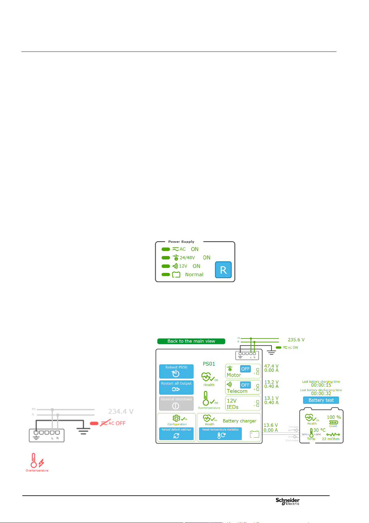
Information displayed for the PS50 Module
This graphical representation contains the following information:
The status of the power supplies managed by the PS50 module, respectively:
The AC line supply
The 24/48 VDC power supply for the switch motor mechanism
The 12 VDC power supply for the transmission equipment
The battery
A Reset button for restarting the power supplies in the event of an outage
following a potential issue on one of the outputs
Power supply shutdown
A power supply shutdown occurs when the mains power supply has been switched
off for a long time, in order to limit the time on the backup power supply (battery).
This power interruption preserves the capacity of the battery and its lifetime.
Battery backup saving can be enabled or disabled by configuration.
When this function is enabled, as soon as the MV network is switched off, the
battery takes over the power supply for a configurable maximum period Backup
time duration (default: 16 hours).
Beyond this period, an immediate alarm General shutdown is activated and then
Power supply is switched off automatically. The power supply is also switched off if
the battery reachs low level and then PS50 module enters sleep mode until the AC
network voltage returns.
From this sleep mode, the 24/48 V & 12 V power supply outputs can be
reactivated temporarily when the PS50 module is reset (Reset button
the External Reset digital input of the PS50 module is activated. The power
supply is switched off again and permanently if it reach the critical discharge
threshold (< 10.8 V).
Extended display for the PS50 Module
By clicking on the graphical representation of the PS50 above, additional
information appears on the right-hand side of the screen including states,
measurements, and the possible actions.
) or when
Examples of potential issues displayed in red
NT00378-EN-03
Under normal conditions, the information is displayed in green. In the event of an
anomaly, the information is displayed in orange or red depending on the severity of
the condition.
19
Page 20

Commissioning Data Consultation and Monitoring
pages
A Reboot PS50 button for restarting the PS50 module. This action performs a complete reboot of
the T300 device.
The extended information included in the detailed view of the PS50 module is
described in the table below:
A Restart all outputs button for restarting all outputs. This may reset the outputs to their initial state
if this is possible and if the anomaly is temporary.
A General shutdown button that can only be activated if there is no AC line supply and power is
supplied by the battery only. Click this button to switch all T300 power supplies to standby mode
and thereby conserve battery power. It is possible to exit standby mode, either manually by pressing
the Reset button on the front of the PS50, or automatically when the AC line supply is restored.
A Reload default settings button for clearing the current parameters and returning to the
PS50 module default parameters.
A Health symbol indicating the overall state of the PS50 and an Overtemperature symbol indicating
the state of the PS50 module thermal protection.
A symbol indicating the state of the 24/48 V switch motor mechanism power supply with an
ON/OFF button for turning this power supply on or off.
A voltage measurement and a consumption measurement are also displayed for this power supply.
A symbol indicating the state of the 12 V transmission power supply with an ON/OFF button for
turning this power supply on or off.
A voltage measurement and a consumption measurement are also displayed for this power supply.
A symbol indicating the state of the general 12 V power supply for the T300 modules and IEDs.
A voltage measurement and a consumption measurement are also displayed for this power supply.
This section displays the overall state of the battery charger with a Reset temperature
statistics button to clear the stored minimum and maximum battery temperatures.
A voltage measurement and a consumption measurement are also displayed for the battery.
A symbol for the presence/absence of the AC line supply with the corresponding voltage
measurement.
Two time indications and a button:
Last battery charging time: Duration of the battery's last charging period
Last battery discharging time: Duration of the battery's last discharging period
Battery test button for activating the battery test immediately. The battery test is theoretically
conducted automatically depending on the period defined in the Automatic test
interval parameter (default setting: 1 day).
Note : The button is not displayed if the battery is disconnected, if battery
potential issue is detected, or if the AC supply is missing.
A graphical representation of the overall status of the battery, including:
Overall battery health indication
Percentage battery charge remaining
Internal resistance measurement in mOhm
The temperature measured in the PS50 operating environment (measurement made internally
in the PS50 box) with an indication of the minimum and maximum values recorded since the
last statistics reset (see
An indication of whether the battery is charging or discharging via arrows showing the direction
of the current. The measurement indicated at the charger level (see
value for this current.
)
) gives a measurement
20
NT00378-EN-03
Page 21

Commissioning Data Consultation and Monitoring
r
r
r
pages
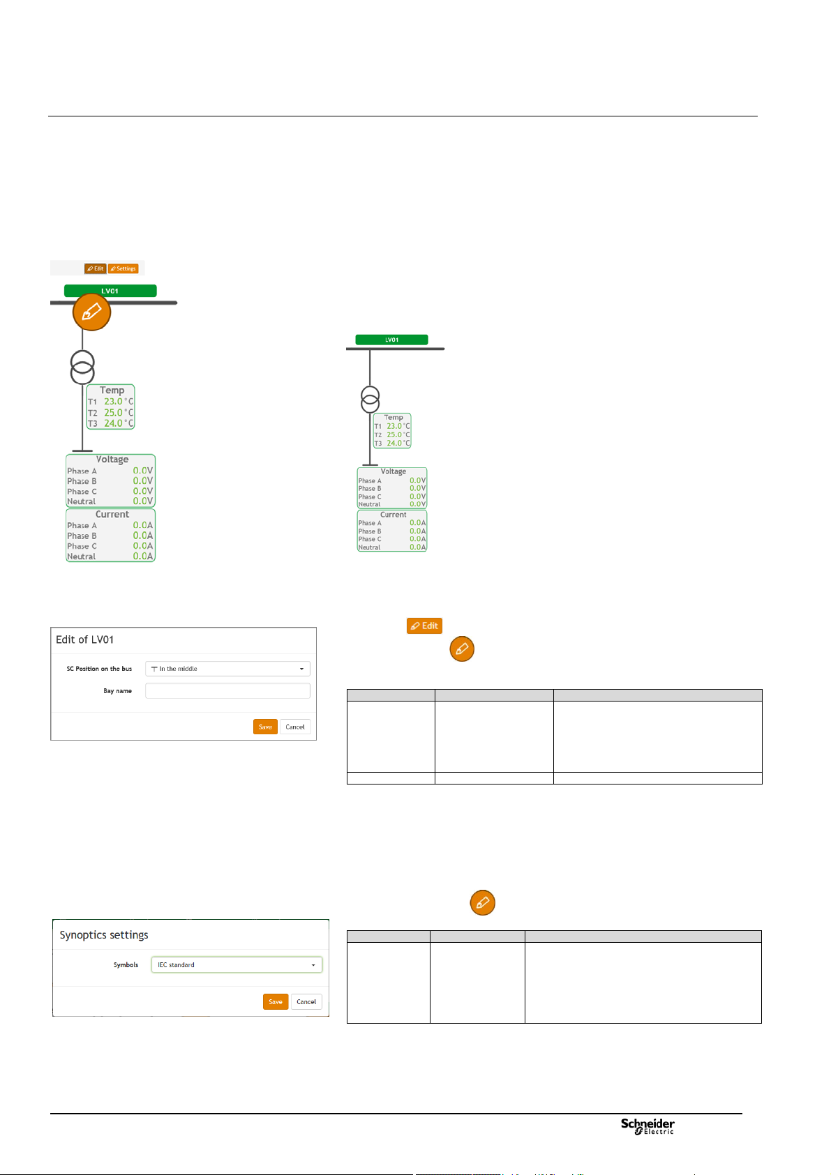
Information displayed for the SC150 modules
Each switch managed by a SC150 module is represented graphically with the
following indications:
Position of the switch (open or closed)
Position of the ground switch (open or closed)
Presence of the MV voltage (ON or OFF)
Display of the RMS current and voltage measurements for each phase
Indication of the presence of a fault current by a red flash and an arrow
indicating the direction of the fault current (for directional fault current detection):
o Green arrow = in the direction of the busbar
o Red arrow = in the direction of the network
Button for editing the graphics parameters associated
with switches
Window for setting the parameters of the graphic
objects associated with a switch
Graphical representation of the Switch
It is possible to customize the graphical representation of each switch by clicking
the button at the top of the page.
Click the edit button that appears in the page to access the graphic
parameters for the switch you want to customize.
A window appears offering the following choices:
Parameter Possible choices Description
SC Position on the bus
Switch type
Line output
VT presence
CT presence
Bay name Name given to the channel
Not connected
On the left
On the right
In the middle
Disconnector
Load switch
Switch disconnector
Circuit breaker
Not any output
Cable
LV0x
No
Yes
No
Yes
Choice of position of the switch on
the busbar:
No link with the busbar
On the left
On the right
In the middle
Choice of switchgear represented:
Disconnector
Load switch
Switch disconnector
Circuit breake
Choice for the representation of
the line downstream of the switch
Choice of whether or not to display
the voltage measurement
transforme
Choice of whether or not to display
the current measurement
transforme
NT00378-EN-03
21
Page 22

Commissioning Data Consultation and Monitoring
pages
Dummy switch
position
Dummy switch position LED on the front panel of the
SC150 module
Extended display for the SC150 module
By clicking on the graphical representation of the switch, additional information
appears on the right-hand side of the screen including counters
and measurements:
Information relating to the switch is displayed in the same way as in the
standard representation. There is also an option to send a command to the
switch by clicking the or button (depending on its
actual position). The graphical representation of the switch is automatically
updated as soon as the change of state is detected.
The general fault current counters representing the total number of phase-to-
phase and phase-to-ground (earth) fault currents detected are displayed by type
(transient, semi-permanent, and permanent), with the option to reset the counter
values by clicking the Reset button .
The detected phase-to-phase fault current counters are displayed by type
(transient, semi-permanent, and permanent), with the option to change the values
by clicking the Edit button.
The detected phase-to-ground (earth) fault current counters are displayed by
type (transient, semi-permanent, and permanent), with the option to change the
values by clicking the Edit button.
The number of operations counted on the switch is given, with the option to
change the value by clicking the Edit button .
The T300 includes the option to configure 2 sets of fault current detection
parameters (with specific values for each set) in the Settings section of the Web
server (see the corresponding section in this manual). The option is given here to
select which set of parameters to apply to fault current detection by clicking or
. The active group is indicated by a green LED.
A Simulation section that is used to test a command on a dummy switch
without actually actuating it (this can be useful to test T300-SCADA
communication when it is not physically possible to operate the switch due to an
interruption on the MV network). To do this, click on the or
retransmission of the change of state remotely (e.g. at the SCADA end). The
position of the dummy switch changes state in this Simulation section of the
application but the actual position of the MV switch (indicated in
change.
After a command is sent to the dummy switch, its position is indicated for
30 seconds on the first customized LED on the SC150 module.
button to operate dummy switch and, for instance, check the
) does not
The instantaneous current measurements for each phase as well as the
residual current
The instantaneous voltage measurements for each phase.
22
NT00378-EN-03
Page 23
Commissioning Data Consultation and Monitoring
pages
Information displayed for the LV150 modules
Each LV150 module has its own graphical representation including the display of
the following information:
The temperature measurements provided by the three PT100 sensors
connected to the LV150
The LV current measurements on each phase and neutral
The LV voltage measurements on each phase and neutral.
Note: The neutral current measurement displayed corresponds to a measured
value in case the 3-phase + neutral sensors mounting is used and to a calculated
value (by summing all 3 phases) when the neutral is not connected.
Button for editing the graphics parameters associated
with LV150
Window for setting the parameters of the graphic
objects associated with LV150
Window for selecting the standard for the graphical
representations
Graphical representation of LV150:
It is possible to customize the graphical representation of each LV150 module by
clicking the button at the top of the page.
Click the edit button that appears in the page to access the graphic
parameters for the LV150 you want to customize.
A window appears offering the following choices:
Parameter Possible choices Description
LV Position on
the bus
Bay name Name given to the channel
Synoptics settings
Click the settings button to define the type of graphical representation to
apply for the objects displayed in the page's synoptics:
Parameter Possible choices Description
Symbols
Not connected
On the left
On the right
In the middle
IEC standard
ANSI standard
Choice of position of the LV150 on the
busbar:
No link with the busbar
On the left
On the right
In the middle
The standard used relates to the representation of
the switchgear, voltage and current transformers,
and the ground switch:
Objects represented in accordance with the IEC
standard.
Objects represented in accordance with the
ANSI standard.
NT00378-EN-03
23
Page 24

Commissioning Data Consultation and Monitoring
pages
Monitoring & Control/Physical view page – Web server
Overall HU250 module status
Overall PS50 module status
3.1.3 System Page
Accessed via: Monitoring & Control/System page
This page provides a general overview of the system. The states of the various
items (modules) are given by symbols indicating a correct operation or potential
issue conditions. The indications given by theses states are detailed by module
here after.
HU250 Module Status
This representation includes:
The status of the Wi-Fi access and the K7 3G/4G modem with a 5-bar GSM
signal strength indicator, and indication of the IP address if connected to the
mobile network.
The status of the HU250 module itself, including the configuration, the PLC,
the GPS reception, the synchronization of equipment and a percentage value
representing the CPU usage level.
Note: The GPS reception symbol indicates the satus of GPS reception with a
color:
- gray: unconfigured or invalid GPS reception.
- green: operational GPS reception.
- red: GPS reception potential issue.
Note 2: A GPS reception issue causes a loss of synchronization and the
corresponding symbol becomes red.
PS50 Module Status
This representation includes:
An indication of the type of link used for the internal HU250-PS50 link (RS485
in Modbus protocol).
The status of the PS50 module, the charger, and the battery, as well as the
overall status of the internal Modbus RS485 link.
LV150 and SC150 Modules Status
This representation includes:
An indication of the type of link used for the internal link between HU250
module and SC150/LV150 modules (Ethernet LAN in IEC 60870-5-104 protocol).
The status of the SC150 and LV150 modules, including for each the status of
the configuration and synchronization, as well as the overall status of the internal
IEC 60870-5-104 Ethernet LAN.
Overall SC150 and LV150 modules status
24
NT00378-EN-03
Page 25

Commissioning Data Consultation and Monitoring
pages
Example of a pop-up window displayed for the
Configuration section of a module
Example of a pop-up window displayed for the
Synchronization section of a HU250 module and
SC150/LV150 module
Example of a pop-up window displayed for the Modem
section of a module
Example of shortcuts available by clicking on the
module representation
Extended display
By passing the mouse over some graphical elements of the modules in the System
page, a "pop up" window appears giving additional indications.
This additional display concerns the following:
1. Configuration: By passing the mouse over the Conf element of a module,
the system indicates the following informations:
The minimum software required for compatibility with the module
configuration.
The options installed on the module (eg details of installed power
2. Synchronization: By passing the mouse over the Synchro element of a
3. Modem: by passing the mouse over the graphical representation of a 3G/4G
measurement options).
module, the system gives the following indications:
For the HU250 module:
o Status of the two synchronization sources (primary and secondary).
For the SC150 and LV150 modules:
o Status of the module time synchronization and status of the
synchronization source generating this synchronization.
o Status of the "1Hz" module synchronization as well as the status of
this synchronization 1Hz signal. This synchronization allows all the
SC150 and LV150 modules to be synchronized to the same 1 Hz
frequency top generated by the HU250 module.
modem, the system indicates the following informations:
Type of modem installed (2G, 3G or 4G modem).
Received GSM signal strength, numbered from 0 to 99:
o 0 to 10: insufficient GSM reception
o 11 to 31: correct GSM reception
o 99: undetectable GSM signals.
The IP address obtained for the T300, assigned by the mobile operator.
The modem IMEI code, allowing identification of the equipment
connecting to the mobile network.
Shortcut to pages
By clicking on the graphical representation of a module, a pop-up window appears
giving the possibility to access directly certain pages of the Web server linked to
this module, like shortcuts or quick accesses.
Depending on the type of module, quick access can be of different types:
PS50: shortcuts to the PS50 module configuration page (Settings page) and
the PS50 module status display page (Subview of PS page).
Other modules: shortcuts to the system events page (Diagnostics-
>System page) and the module settings page (Settings page).
NT00378-EN-03
25
Page 26

Commissioning Data Consultation and Monitoring
pages
Monitoring & Control / Status page – Web server
3.1.4 Data Pages
Accessed via: Monitoring & Control/Status-Command-Analog-Setpoint page
There are 4 pages in the T300 Web server for viewing status and measurement
data or for sending commands:
Status page: For viewing the status of the digital data
Command page: For sending change of state commands based on the
digital data
Analog page: For viewing measurement values
Setpoint page: For forcing parameter values
Each page has the same format, with the following information displayed on
the screen:
The data refresh period can be configured in 1 of 3 ways:
o Fast: Data is refreshed every second
o Normal: Data is refreshed every 4 seconds
o Slow: Data is refreshed every 10 seconds
It is also possible to set a filter to display data by Source or Destination to limit
the amount of data displayed on screen:
The description of a data item is displayed over 3 main columns:
o Point name Internal name of the data item in CoreDb (database)
o Description Data label
o Value Value of the data item
By clicking the button associated with the Value field, you can manually
edit the state or value of a Command or Setpoint data item:
Note: For switch control, it is advisable to use the interface in the Substation view.
26
NT00378-EN-03
Page 27

Commissioning Data Consultation and Monitoring
pages
Example of Analog data display
Similarly, for a Status or Analog data item, you can force its status or value.
However, this type of data is only processed in read mode; forcing is only
applied in simulation.
To do this, the actual data item must first be locked by clicking the Locking option.
Once the data is locked, the button associated with the Value field then
becomes accessible and can be used to change its status or value in
simulation mode.
Note: The modified value also impacts the remote retransmission at the
SCADA end. This allows you, for instance, to simulate the state of a variable
and to test its retransmission at the SCADA end, without affecting the actual
equipment operation.
Disabling the Locking option cancels the simulation and returns to the actual
status or value of the data item.
Two icons displayed in the Quality column provide an indication of the data
processing quality. The quality of a data item can give an indication of the
validity of the status or value entered on the Web server page.
This quality is indicated for the following 2 sources:
o Local source: Reflects the quality of the data item from the viewpoint
of its processing at the HU250 end
o Remote source: Reflects the quality of the data item sent by the
information source (device) processing the data (e.g. SC150, PS50, etc.)
NT00378-EN-03
In the same way as for a change of state or value for Status or Analog
it is possible to manually simulate the quality of a data item.
To do this you must first lock the data item using the Locking option,
then click the button associated with the Quality field.
The possible choices for the local and remote source quality are then displayed
on screen.
Disabling the Locking option cancels the simulation and returns to the actual
quality of the data item.
data,
27
Page 28
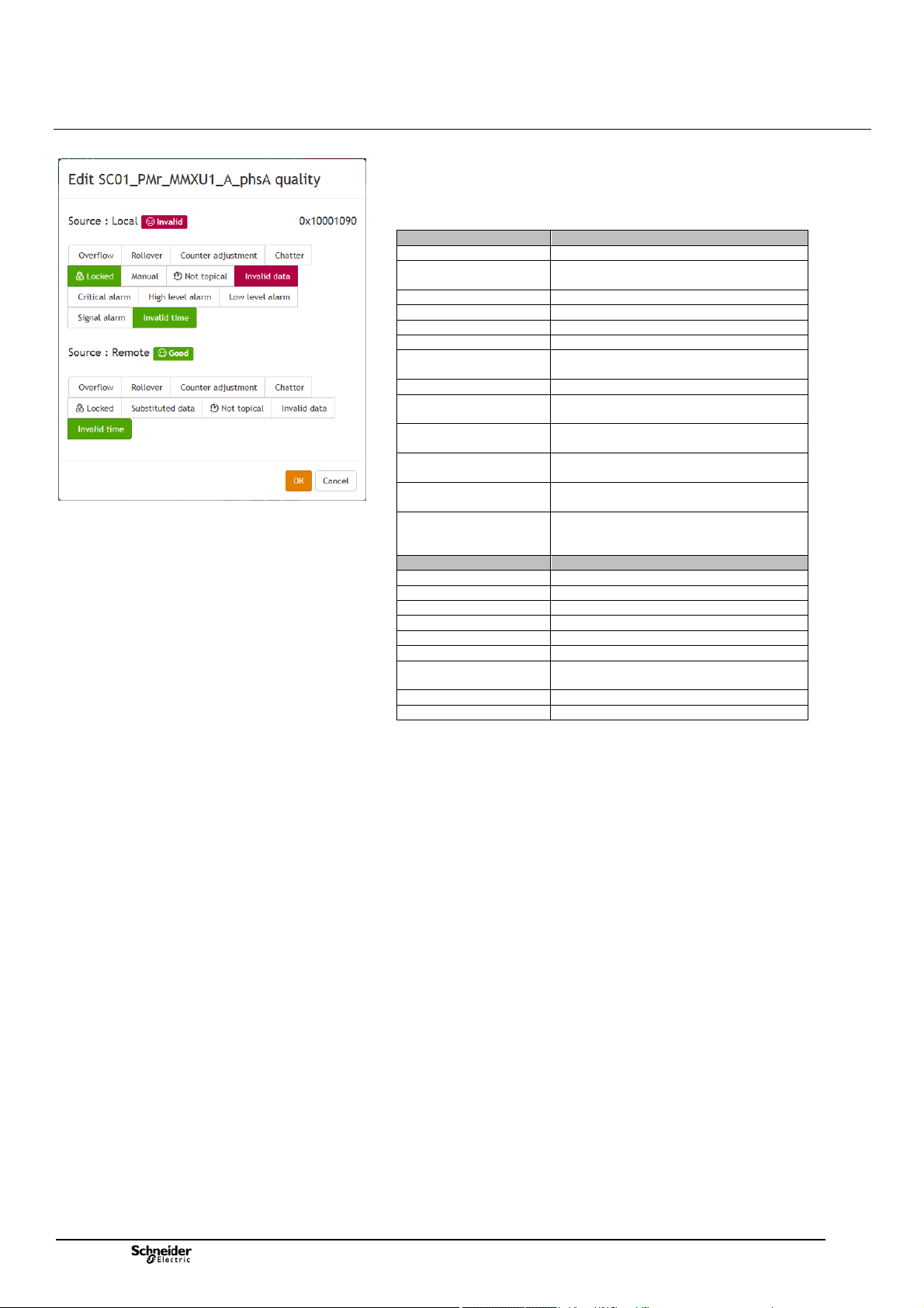
Commissioning Data Consultation and Monitoring
r
pages
Choice of quality options for the local and remote sources
The table below shows the correspondence of the different quality types that can
be simulated after having locked a data item.
Note that this also gives an indication of the different quality types that can be
obtained in actual operation:
Local source quality Description
Overflow An overflow has occurred on a counter
Rollover An overflow and an automatic reset have
Counter adjustment The counter has been adjusted
Chatter Excessive change on a digital input
Locked The data item is locked
Manual The data item has been manually replaced
Not typical The data item has not yet been written to
Invalid data Data item is invalid
Critical alarm The value of the data item has exceeded
High level alarm The value of the data item has exceeded
Low level alarm The value of the data item is below the Low
Signal alarm The value of the data item is below the
Invalid time The data item time-stamp is invalid or
Remote source quality Description
Overflow An overflow has occurred
Rollover A rollover has occurred on a counter
Counter adjustment The counter has been adjusted
Chatter Excessive change on a digital input
Locked The data item is locked
Substituted data The data item has been manually replaced
Not topical The data item has not yet been written
Invalid data Data item is invalid
Invalid time The data item time-stamp is invalid
occurred on a counte
the database
the High-High alarm threshold
the High alarm threshold
alarm threshold
Low-Low alarm threshold
inaccurate (the HU250 is not synchronized
by a source)
to the database
28
NT00378-EN-03
Page 29

Commissioning The Measures
A
Example of measurements displayed – MV or LV
Measurement/PM – Power page / RMS tab
3.2 Measurements
3.2.1 Measurements Pages
Accessed via: MV and LV Measurements/PM-Power/PM-Energy/Power-Quality
page
The MV and LV Measurements pages in the Web server display the different
types of power, energy, and quality measurements taken by the T300 on the MV
and LV networks, in tabs including data tables based on the analog data received
from the current and voltage sensors.
Note: Regarding MV voltage measurement, the T300 takes the measurements
using the same current and voltage sensors as those used to detect fault currents.
The power and energy measurements comply with standard IEC 61557-12.
The power quality measurements are completed according to the principles of IEC
61000-4-30 class S (up to harmonic 15).
Note: To comply with the accuracy required by the standards (1% accuracy),
voltage measurements are only possible using LPVT or VT type adaptors (for LV
measurement; only Voltage adaptor type).
Some measurements are optional for the T300 ("option" column in the table
below). If the corresponding option is not present in the equipment, the associated
data is not displayed in the LV and MV Measurements pages.
Note: The PM option (and associated measurements) is included as standard for
LV measurements, although this is optional for MV measurements.
The data displayed in the MV Measurements page depends on the parameter
settings in the Settings/SC0x/Measurements and Power Quality pages.
The data displayed in the LV Measurements page depends on the parameter
settings in the Settings/LV0x/Measurements and Power Quality pages.
Refer to the corresponding sections for more information on how to configure
these parameters.
The list of measurements displayed in the MV and LV Measurements pages is
identical and shown below:
Category Measure Description Option
Current Mean Mean current on all 3 phases
Single
voltage
Phase
voltage
Real power Total Total active power
Reactive
power
Apparent
power
Power
factor
(*): PM option is incuded as standard for the LV measurements.
Phase A Current on phase A
Phase B Current on phase B
Phase C Current on phase C
Residual Residual current
Mean Mean phase-to-neutral voltage on all 3
phases
Phase A Phase-to-neutral voltage on phase A
Phase B Phase-to-neutral voltage on phase B
Phase C Phase-to-neutral voltage on phase C
Neutral Residual voltage
Mean Mean phase-to-phase voltage on all 3 phases
Vab Phase-to-phase voltage between phases A
and B
Vbc Phase-to-phase voltage between phases B
and C
Vca Phase-to-phase voltage between phases C
and
Phase A Active power on phase A
Phase B Active power on phase B
Phase C Active power on phase C
Total Total reactive power
Phase A Reactive power on phase A
Phase B Reactive power on phase B
Phase C Reactive power on phase C
Total Total apparent power
Phase A Apparent power on phase A
Phase B Apparent power on phase B
Phase C Apparent power on phase C
Total Total power factor
Phase A Power factor on phase A
Phase B Power factor on phase B
Phase C Power factor on phase C
Tab PM - Power
Tab RMS
No option
(included
as
standard)
PM option
(*)
NT00378-EN-03
29
Page 30
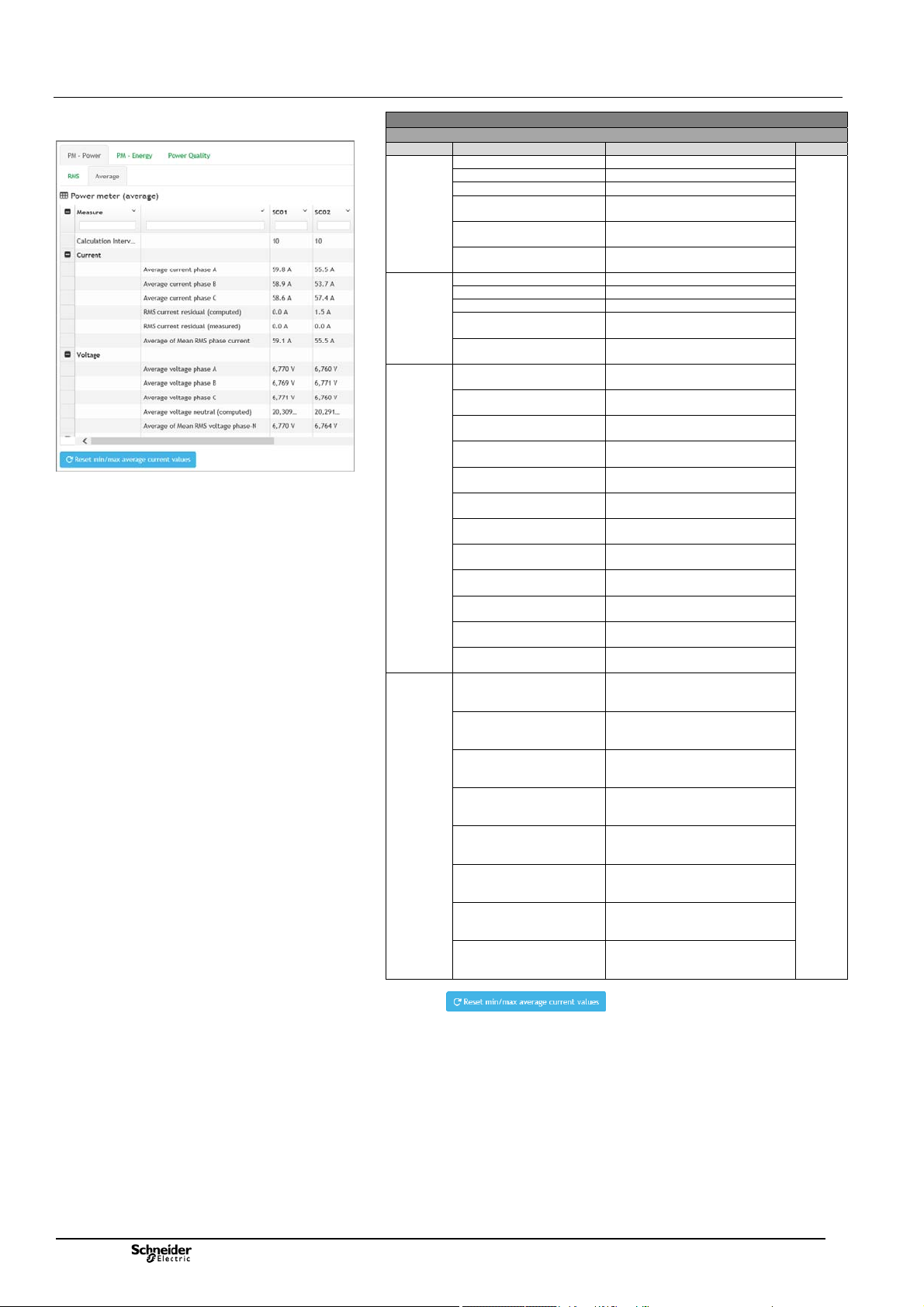
Commissioning The Measures
A
A
A
A
y
r
y
year
Example of measurements displayed – MV or LV
Measurement/PM – Power page / Average tab
Category Measure Description Option
Current Average current phase A Average current phase A
Voltage Average voltage phase A Average voltage phase A
Power Average P Real power
Min/Max
recording
(*): PM option is incuded as standard for the LV measurements.
(°) :A button on the page manually resets the calculated
averages on the currents.
Average current phase B Average current phase B
Average current phase C Average current phase C
RMS current residual
(computed)
RMS current residual
(measured)
Average of Mean RMS
phase current
Average voltage phase B Average voltage phase B
Average voltage phase C Average voltage phase C
Average voltage neutral
(computed)
Average of Mean RMS
voltage phase-N
phase
Average P Real power
phase B
Average P Real power
phase C
Average P Real power
total
Average Q Reactive
power phase
Average Q Reactive
power phase B
Average Q Reactive
power phase C
Average Q Reactive
power total
Average S Apparent
power phase
Average S Apparent
power phase B
Average S Apparent
power phase C
Average S Apparent
power total
Minimum of average of
Mean RMS phase current
da
Minimum of average of
Mean RMS phase current
week
Minimum of average of
Mean RMS phase current
month
Minimum of average of
Mean RMS phase current
yea
Maximum of average of
Mean RMS phase current
da
Maximum of average of
Mean RMS phase current
week
Maximum of average of
Mean RMS phase current
month
Maximum of average of
Mean RMS phase current
Tab PM - Power
Tab Average (°)
RMS current residual (computed)
RMS current residual (measured)
Average of Mean RMS phase
current
Average voltage neutral (computed)
Average of Mean RMS voltage
phase-N
Average P Real power phase A
Average P Real power phase B
Average P Real power phase C
Average P Real power total
Average Q Reactive power phase A
Average Q Reactive power phase B
Average Q Reactive power phase
C
Average Q Reactive power total
Average S Apparent power phase
Average S Apparent power phase
B
Average S Apparent power phase
C
Average S Apparent power total
Minimum of average of Mean RMS
phase current day
Minimum of average of Mean RMS
phase current week
Minimum of average of Mean RMS
phase current month
Minimum of average of Mean RMS
phase current year
Maximum of average of Mean RMS
phase current day
Maximum of average of Mean RMS
phase current week
Maximum of average of Mean RMS
phase current month
Maximum of average of Mean RMS
phase current year
PM
Option
(*)
30
NT00378-EN-03
Page 31

Commissioning The Measures
Example of measurements displayed – MV or LV
Measurement/PM – Energy
Example of measurements displayed – MV or LV
Measurement/Power Quality / Quality tab
Category Measurement Description Option
Real
energy
Reactive
energy
Positive
reactive
energy
Negative
reactive
energy
Apparent
energy
(*): PM option is incuded as standard for the LV measurements.
(°) :A button on the page manually resets the energy counters.
Total Total active energy
Phase A Active energy on phase A
Phase B Active energy on phase B
Phase C Active energy on phase C
Demand Total active energy consumption
Supply Total active energy supplied
Total Total reactive energy
Phase A Reactive energy on phase A
Phase B Reactive energy on phase B
Phase C Reactive energy on phase C
Demand Total reactive energy consumption
Supply Total reactive energy in supply
Demand Total positive reactive energy
Supply Total positive reactive energy in supply
Demand Total negative reactive energy
Supply Total negative reactive energy in supply
Total Total apparent energy
Phase A Apparent energy on phase A
Phase B Apparent energy on phase B
Phase C Apparent energy on phase C
Category Duration Measur-
Voltage 10 min Mean
2 hours Mean
Unbalance
negative
sequence
150/180
cycles (*)
10 min Current
2 hours Current
Dips swells
and
interruption
(*): 150 measurement cycles corresponds to 3 secondes at 50 Hz. 180 measurement cycles
corresponds to 3 secondes at 60 Hz.
Short Dip Short voltage sag indication
Medium Dip Medium voltage sag indication
Long Dip Long voltage sag indication
ement
Phase-N
Phase A Mean voltage on phase A over 10 minute
Phase B Mean voltage on phase B over 10 minute
Phase C Mean voltage on phase C over 10 minute
Neutral Mean residual voltage flowing in the
Phase-N
Phase A Mean voltage on phase A over 2 hour
Phase B Mean voltage on phase B over 2 hour
Phase C Mean voltage on phase C over 2 hour
Neutral Mean residual voltage flowing in the
Current
unbalance
Voltage
unbalance
unbalance
Voltage
unbalance
unbalance
Voltage
unbalance
Swell Short voltage swell indication
Interruption Short voltage interruption indication
Swell Medium voltage swell indication
Swell Long voltage swell indication
Interruption Long voltage interruption indication
(°) :A button on the page manually resets the quality event counters.
Tab PM – Energy (°)
consumption
consumption
Tab Power Quality
Tab Quality (°)
Description Option
Mean voltage on each phase and neutral
over 10 minute period
period
period
period
neutral over 10 minute period
Mean voltage on each phase and neutral
over 2 hour period
period
period
period
neutral over 2 hour period
Current unbalance over 3 seconde period
Voltage unbalance over 3 seconde period
Current unbalance over 10 minute period
Voltage unbalance over 10 minute period
Current unbalance over 2 hour period
Voltage unbalance over 2 hour period
PM option
(*)
PQ
option
NT00378-EN-03
31
Page 32

Commissioning The Measures
V
V
V
Example of measurements displayed – MV or LV
Measurement/Power Quality / Harmonics tab
Voltage phase A total harmonic
distortion
Voltage phase B total harmonic
distortion
Voltage phase C total harmonic
distortion
Voltage total harmonic distortion
average of 3 phases
Voltage phase A harmonic 1
magnitude
Voltage phase B harmonic 1
magnitude
Voltage phase C harmonic 1
magnitude
Voltage harmonic 1 average of 3
phases
oltage phase A harmonic 1 angle Voltage phase A harmonic 1 angle
oltage phase B harmonic 1 angle Voltage phase B harmonic 1 angle
oltage phase C harmonic 1 angle Voltage phase C harmonic 1 angle
Current phase A total harmonic
distortion
Current phase B total harmonic
distortion
Current phase C total harmonic
distortion
Current total harmonic distortion
average of 3 phases
Current phase A harmonic 1
magnitude
Current phase B harmonic 1
magnitude
Current phase C harmonic 1
magnitude
Current harmonic 1 average of 3
phases
Current phase A harmonic 1 angle Current phase A harmonic 1 angle
Current phase B harmonic 1 angle Current phase B harmonic 1 angle
Current phase C harmonic 1 angle Current phase C harmonic 1 angle
Measurement Description Option
Note: Rank 2 to 15 harmonics are not available in the MV and LV Measurement
pages. Nevertheless, they are displayed in the Monitoring &
control/Data/Analog pages. See also the T300 Database Manual (ref. NT00391),
for the details of the variables corresponding to harmonics 1 to 15.
Tab Power Quality
Tab Harmonics
Voltage phase A total harmonic distortion
Voltage phase B total harmonic distortion
Voltage phase C total harmonic distortion
Voltage total harmonic distortion average of 3
phases
Voltage phase A harmonic 1 magnitude
Voltage phase B harmonic 1 magnitude
Voltage phase C harmonic 1 magnitude
Voltage harmonic 1 average of 3 phases
Current phase A total harmonic distortion
Current phase B total harmonic distortion
Current phase C total harmonic distortion
Current total harmonic distortion average of 3
phases
Current phase A harmonic 1 magnitude
Current phase B harmonic 1 magnitude
Current phase C harmonic 1 magnitude
Current harmonic 1 average of 3 phases
PQ
Option
32
NT00378-EN-03
Page 33

Commissioning Diagnostic Files
Diagnostic/Events page – Web server
Sorting data displayed by column
3.3 Diagnostic Files
The T300 includes log files that can be viewed in the Web server for performing
diagnostics on the equipment.
Three files are created by default:
An events file, displayed in the Events page (default capacity: 2,000 events).
A system status file, displayed in the System page.
A Cyber Security status file, displayed in the Security page.
The overall storage capacity for all diagnostic files is 500,000 events.
Note: Other diagnostic files can be added by configuring them in the T300 Web server
(a maximum of 4 diagnostic files in total). The Events file configuration can also be
modified, for instance, to change the type of data displayed or to modify the file size.
To do this, refer to the dedicated SOE User Manual or the T300 Quick Start Guide.
Note that the System file cannot be modified by configuration.
The data recording parameters are saved in the log files according to the
definition in Easergy Builder:
o It is possible to define up to 4 log files.
o The size and name of each log file is configurable.
o Any data can be assigned to a log file.
By clicking the button, the log files can be downloaded locally and
remotely in .csv format (respecting the standard RFC4180 format), which means
they are compatible with Excel or any other spreadsheet package.
By clicking the button, the data displayed is immediately refreshed.
Clicking the button clears all events at once. Confirmation is requested to
help avoid the potential for inadvertant operator selection.
Data can be sorted by clicking the title of a column and selecting the sort option
required.
For all logs, when the storage capacity is reached, the most recent event erases
the oldest event from the list.
3.3.1 Events Page
Accessed via: Diagnostic/Events page
This page is used to view events associated with changes of state on data items.
These are recorded in real time by the T300 and time-stamped with a
1 ms resolution.
On a change of state, an event is recorded in the file using predefined
descriptions specific to each state or measurement unit.
The name of the data item and its corresponding description are given on this
page as well as the source that processed the data item that generated the event.
NT00378-EN-03
33
Page 34

Commissioning Diagnostic Files
3.3.2 System Page
Accessed via: Diagnostic/System page
The T300 integrates the option to save additional internal system data for
operation and maintenance purposes.
This data informs the user of any potential internal anomalies or potential
operating issues in the system.
One tab per module is displayed on this page. Each tab contains the system
information or the ERRORS generated by the module concerned (HU250, SC150
or LV150).
The messages displayed on each tab are categorized into 3 different types:
INFO: Normal information on actions executed by the module
WARNING: Messages that need to attract the user's attention regarding
possible anomalies
ERROR: Potential issue detected by the system that could downgrade
operation
Diagnostic/System page – Web server
Tip: a sort in the Level column can be performed (by typing the first letters of the
desired level) to display the information by category:
3.3.3 Cyber-Security Page
Accessed via: Diagnostic/Cyber Security page
This page displays the Cyber Security logs. All information about user connections
to the web server is saved as simple information (INFO) or security alerts
according to the level of importance (WARNING or EMERGENCY).
The name of the user making the connection is logged in order to identify who is
trying to connect. A "WARNING" type message is logged for each authentication
error. An "EMERGENCY" message is logged for users whose access is blocked
after a certain number of failed attempts (see chapter SAT and RBAC - System
Security Parameters for details on the T300 security policy).
Note: This page can be accessed in the Web server only by users who have the
"SECADM" role (see section System Cyber-Security for more information on
user roles and access rights).
Diagnostic/Cyber security page – Web server
34
NT00378-EN-03
Page 35

Commissioning The traces
Diagnostic/Traces page – Web server
Example of trace with a Modbus protocol (HU250PS50 communication).
3.4 Traces
3.4.1 Protocol Traces
Accessed via: Diagnostic/Trace page
From the Trace pages, you can display the exchanges on the different
communication channels of the T300. For example, you can view internal
communications between the T300 modules, or external communications between
the T300 and the IEDs or between the T300 and a SCADA.
In the Communication section, from the communication channels available in the
unit, select the traces to display. The available channels depend on the initial
configuration of the equipment.
It is also possible to display the communication of AT commands between the
HU250 and the modems. To display the AT commands in a trace, go to the
Modems/Links section and select Modem1, Modem2, or both.
In addition to the exchanges related to communication and modems instructions, it is
also possible to display in the trace any new event occurring to the CoreDb
database, by selecting All events.
when the elements are selected for the trace, click the button
to display the corresponding trace in a new page.
Trace display
In the Trace page, each frame received or sent by the T300 is identified by a symbol
and a unique number at the beginning of the line. This number and this symbol make
it possible to identify the corresponding communication channel, modem or event.
Each line in the trace contains a timestamp indicating when the communicaton was
sent or received. For frames and AT commands, the timestamp is at the beginning of
the line. For events, the timestamp is at the end of the line.
A frame corresponding to an exchange by a protocol is displayed in hexadecimal.
An AT command instruction is displayed in text.
A database event is displayed with the name of variable and the new state or value
associated with it.
For certain protocols, the end of the line may gives additional informations on the
nature of the frame ("Read" or "Write" function, for example in Modbus protocol).
When the page capacity is reached (1000 lines maximum), the trace is recorded in
sub-pages classified and numbered in order of trace appearance.
To pause scrolling of the trace but continue to record trace information, click the
button.
To stop recording trace information, click the button.
To start or restart recording trace information, click the button.
Example of trace with modem AT commands
Example of trace with CoreDb database events.
NT00378-EN-03
To export trace information into a text file, click the button. The text file
contains the information that is displayed on the Trace page.
The button is displayd when trace recording has been stopped
manually. Click thjis button to return to the trace selection page.
Note: The IEC61850 protocol can not be displayed in the trace.
35
Page 36

Commissioning Cyber-Security
Maintenance/Users page – Web server
3.5 System Cyber-Security
3.5.1 Users and roles
Accessed via: Maintenance/Users page.
3.5.1.1 SAT and RBAC
SAT is the T300 security administration tool for managing the security policy and
defining the restrictions for accessing the system or the communication interfaces.
It is a software tool for installing on a PC.
The T300 security policy consists in structuring the rights and responsibilities within
the system and defining who is authorized to do what, when, and how, based on an
RBAC (role-based access control) model.
The access is controlled via roles. A role is a set of permissions, and users receive
these permissions via the role to which they are assigned.
This RBAC model allows the T300 to:
secure local and remote connections for maintenance: HTTPS, SSH
secure file transfer protocols: SFTP
The T300 is supplied with a predefined RBAC model allowing different levels of user
access adapted to T300 usage compliant with standard IEC 62351-8.
It is not strictly necessary, therefore, to modify the permissions and the roles of this
default RBAC model if it is suitable.
This RBAC contains one user per role. These users are configured with passwords
by default. It is imperative to change these passwords either via the SAT or via the
T300 web server.
The SAT can be used to create its own user database along with definition of its own
roles, as well as to manage the RBAC models for each device centrally.
The SAT can be used to manage:
User accounts (add/modify/delete user accounts)
Security of the installed base in the T300
For more information on the SAT, refer to the specific user instructions.
36
NT00378-EN-03
Page 37

Commissioning Cyber-Security
r
3.5.1.2 System Security Parameters
Cybersecurity involves a certain number of system parameters that are applied to
the security policy.
These parameters are summarized in the table below and cannot be modified in the
SAT. Refer to the SAT User Manual for more information on these functions. The
default values in the SAT are given in brackets.
Parameter Description
Idle session timeout After a period of inactivity, user access to the Web
Authorize user lockout Option to lock/unlock a user account (function
Maximum number of
connections
Password timeout Maximum time period allowed for entering password (3
Account auto-unlock Automatic unlocking of a user account after a defined
Account lock duration Maximum time period for an account to remain locked
Password complexity Choice of policy (strength) used for creating or
Monitoring and recording
standards
Syslog server IP address
(*)
Syslog server IP port
(*)
SNMP Client/Server IP
address
Rights activation Options for activating user rights:
High security banner Function not developed in T300
Medium security banner Function not developed in T300
Low security banner Function not developed in T300
(*): A Syslog server has the ability to centralize cyber-security logs. Logs can be
transmited to the Syslog server, that is specified by these two parameters.
server lapses. The user must re-enter their username
and password to reconnect (default setting: 15
minutes).
authorized by default)
The maximum number of connection attempts a user
can make (5 attempts by default)
minutes by default)
duration (see below) if the account has been locked out
(unlocking enabled by default)
(240 seconds by default)
modifying passwords.
3 levels of complexity are possible, compliant with
standards:
None (default):
IEEE Std 1686:
NERC:
List of supported standards:
BDEW (default)
E3
NERC_CIP
IEEE 1686
IEC 62351
CS_PH1
IP address for the Syslog server
(10.22.90.14 by default)
IP port number for the Syslog server
(601 by default)
Function not developed in T300
Cybersecurity rights (default)
Generic rights
o 1 character minimum
o Valid characters: ASCII [33,122]
o 8 characters minimum
o Valid characters: ASCII [33,122], including:
1 lower case letter
1 upper case letter
1 digit
1 special character
(! " # $ % & ' ( ) * , - . / : ; < = > ? @ [ ] ^_ `)
o 6 characters minimum
o Valid characters: ASCII [33,122], including:
1 letter
1 digit
1 non-alphanumeric characte
NT00378-EN-03
37
Page 38

Commissioning Cyber-Security
V
3.5.1.3 Managing Users and Roles in the Web Server
Since the roles and access levels are already predefined in the RBAC model, the
T300 Web server is used to add or delete users, modify passwords, and assign or
modify one or more predefined roles to users (either default roles or those created in
the SAT).
In the default user database, the SecurityAdmin user is the only user with sufficient
rights (SECADM role) to administer T300 cybersecurity actions (see table below).
Consequently, this is the only user who can manage/modify user passwords and
rights (roles):
Default Users
INSTALLER
ENGINEER
Installer X
Engineer X
iewer X
Operator X
SecurityAdmin X
SecAud X
RbacMnt X
You need to connect to the T300 as a SecurityAdmin user to be able to perform the
user and role administration operations described below.
The rights defined for each role are detailed in the table below:
Default Roles
VIEWER
OPERATOR
SECADM
SECAUD
RBACMNT
Rights Defined For Each Role/User
VIEWER
Object Description Action
CONF_DB
CONF_SYS
FIRMWARE HU250 firmware
WEBSERVICE T300 Web server Access X X X X X
SSH Easergy Builder, console Access X X
OS_SHELL
BLMON
SYS_LOG System and SOE log files
RBAC
RBAC_LOG Security log file Deletion X
DATA
RESET Device reset Access X X
T300 application configuration
(HU250, SC150.)
T300 system configuration
(Ethernet, WI-FI, modem box,
etc)
Linux Shell, configuration
import/export service
BLMon tools (trace viewer, AT
commands, etc.)
System security
(users, passwords, access
rights)
Device data
(signals, measurements, controls,
counters, PS50 settings, etc.)
Read X X X X
Write X X
Read X X X
Write X X
Visualizat. X X X
Read X X
Write X X
Access X
Access X X
Read X X X
Deletion X X
Read X
Write X
Read X X X X
Write X X X
OPERATOR
SECADM
ENGINEER
INSTALLER
SAT SAT
Note 1: "SAT" means that this user/role cannot access the Web server, but has the
rights assigned via the SAT only.
Note 2: It is not possible to modify the rights assigned to a role via the T300 Web
server. This can only be done via the SAT. Refer to the SAT manual for more
information on how to administer the roles and associated rights in the RBAC model.
Note 3: To have full access to read and write a configuration in Easergy Builder, you
will need the services "SSH" and "OS_SHELL". So, only the access Engineer allows
this possibility.
SECAUD
RBACMNT
SAT
SAT
38
NT00378-EN-03
Page 39

Commissioning Cyber-Security
3.5.1.4 Modifying User Roles/Passwords
Proceed as follows to change user roles and passwords:
Connect to the T300 via the SecurityAdmin user.
Go to the Maintenance/Users page in the Web server.
This displays the list of existing users.
Click on a user to display the roles assigned to them.
To assign or remove a role from a user, simply check or uncheck the box
next to the specific role in the list. Several roles can be assigned to a
single user, but there must be at least one role per user.
Once the user roles have been modified, click the button to save the
changes.
It is also possible to delete the user by clicking the button.
Confirmation is requested to help avoid an inadvertant operator selection.
Example of default roles assigned to the Installer
user
Changing a user password
Click the button to change the user password. The new
password must be entered twice to confirm it for security reasons.
Password creation rules are defined in the SAT (see the System Security
Parameters section). By default, the password must contain the following:
o At least 1 character
o Valid characters: ASCII code [33,122]
By clicking the button, it is also possible to create a new user
in addition to the default users.
This opens a new window, requesting entry of the password and definition
of the roles for this user. Click to confirm creation of this user.
Note 1: It is possible to lock an existing user by enabling the lock .
The user will then no longer be able to connect using their login (username and
password).
Note 2: It is possible to assign cybersecurity administrator rights to a
predefined user other than SecurityAdmin. This other user can then perform
the same role and password administration tasks for all other users, except
their own.
3.5.1.5 Security Log Event File
A dedicated cybersecurity event file is created in T300. This file logs all events
associated with connections to the T300 and all modification operations linked to the
cybersecurity strategy.
This file can only be accessed by a user with cybersecurity access rights. It can be
viewed and downloaded in the Diagnostic/Security log page in the Web server.
Creating a user for secure access to the T300
NT00378-EN-03
39
Page 40

Commissioning Cyber-Security
r
Centralized
RBAC
RADIUS server SAT
Remote
RBAC
Network
Infrastructure
3.5.2 Centralized authentication with RADIUS
3.5.2.1 Operating principle
Radius protocol provides the capability to use a centralized user database to
authenticate users remotely and provide their RBAC Role on the local system
(T300). This makes it possible to have a generalized and unique authentication
policy on a dedicated server, rather than to define them locally on the various T300s
of the network.
Network Infrastructure
Centralized authentication requires an architecture that includes T300s, a SAT
server, and a RADIUS server connected together via a remote network.
The T300 includes the locally defined authentication policy in the unit. This
policy is used in case of non-availability of centralized authentication.
The SAT server includes the remote authentication policy. It includes all the
individual authentications of each T300 on the same server. Rather than
configuring it locally on each product, it may be useful to define it in one place
on a dedicated server.
The RADIUS server includes the remote centralized authentication policy,
enabling global authentication common to each T300.
The exchange during an authentication between the RADIUS server and the T300
depends on the authentication mode defined:
Locally only (RADIUS server not used)
Locally then centralized, if the requested user is not locally found.
Centralized then locally, if the requested user is not found in centralized.
The operating parameters of the authentication are configured in the SAT.
The RADIUS server
Radius server is part of the network infrastructure in which HU250 (T300) device is
connected to. It provides the centralized database of users and contains:
The dictionary: definition of the list of attributes of user records.
User records: list of the users, respecting the attributes specified in the
HU250
Local
RBAC
HU250 HU250
Local
RBAC
Local
RBAC
dictionary.
User attributes are provided to the Radius client once the user is authenticated.
Hence Radius server provides to HU250 device the following information related to
the authenticated user:
o RBAC Roles,
o Expiration date.
Common Authentication configuration on the SAT
The common authentication parameters are defined in the SAT:
Name Data type Description
Authentication mode Integer
Default role for
centralized
authentication
Centralized
authentication
timeout
Centralized
authentication
protocol
String
Integer
Integer
Indicate the kind of authentication used
1: local
2: local then centralized
3: centralized then local
When one of the 2 centralized option is
selected, the RADIUS tab become active
The role assigned by default when the
centralized access is used and that the role
is not given by the Radius serve
The maximum time for which an
authentication response is expected from
each Radius server.
Configurable from 0 to 99 secondes.
Defines the current protocol managed to
reach a distant authentication Radius server.
1: Radius
2: Samba (not supported)
3: LDAP (not supported)
40
NT00378-EN-03
Page 41

Commissioning Cyber-Security
r
r
j
RADIUS
Client
RADIUS Protocol
RADIUS: Acces-Request
RADIUS: Acces-Accept
RADIUS: Acces-Re
RADIUS
Serve
ect
RADIUS Protocol
Radius has several authentication schemes.
The T300 implements Radius client with PAP scheme (EAP scheme is not
supported for the moment).
In Radius PAP scheme, the client sends an Access request, and the server replies
with Access Accept, or Access Reject.
The exchange uses UDP, on a configurable port (by default 1812).
In order to secure exchanges between client and server (authentication of both
parts, and ciphering of some part of the information), RADIUS uses a shared key
mechanism. This shared secret is pushed using SAT to each HU250 configured to
use this server.
SAT RADIUS Authentification configuration via the SAT
The SAT also allows you to define the configuration parameters of the RADIUS
client in the HU250:
Name Data type Description
Mode Integer
IP address String
Port Integer
Shared Secret String
IP Address
backup
(optional)
Port backup
(optional)
Shared secret
backup
(optional)
Role attribute
name
AoR attribute
name
Date attribute
name
Attributes
separato
Dictionary String
The Radius server has a specific configuration as explained in the current chapter.
HU250 device must know this configuration in order to be able to communicate with
it.
This configuration is divided in 2 categories:
Networking information: IP address, port, Shared Secret.
Protocol parameters:
o The structure of the user database: the dictionary.
o The name of the attribute related to Role and Date in this dictionary, so
that the client can extract them from the Access-Accept response.
o The attributes separator in case an attribute contains a list of values (eg:
multiple roles).
String
Integer
String
String
String
String
String
It indicates the communication mode of the
RADIUS client. Can take the value:
1 = RADIUS_CLEAN
2= EAP-TTLS is not supported
The server IP address expressed in the classic
way of IP address: www.xxx.yyy.zzz
The server port number used for the
communication.
Configurable from 0 to 65535
This is a text string that serves as a password
between the RADIUS client and the RADIUS
server. This field is optional and can have a
maximum length of 32
IP address of the second server, used as
backup (this field is optional)
Port number of the second server, used as
backup (this field is optional)
Text string that serves as a password between
the RADIUS client and the second RADIUS
server, used as backup (this field is optional)
Name of the attribute in the Radius protocol
accepted answer where the role assignment is
stored. It must be identical to the attribute in the
server dictionary
Name of the AoR (Area Of Responsability)
attribute in the Radius protocol accepted answer
where the AoR assignment is stored. It must be
identical to the attribute in the server dictionary.
Remark: AoR exists in SAT but is not supported
by T300. So, the SAT parameter is used by
other devices than T300.
Name of the attribute in the Radius protocol
accepted answer where the date assignment is
stored. It must be identical to the attribute in the
server dictionary
Optional character used inside the attributes (eg
role) to transmit multiple fields
Long string storing contents of RADIUS
dictionary. It must be identical to the Radius
server dictionary. Role, AoR and Date attributes
must be identical to the ones previously filled
NT00378-EN-03
41
Page 42

Commissioning Cyber-Security
3.5.2.2 Exemple of RADIUS server use
This chapter describes a nominal use case with:
Default SAT users that are pushed to HU250. Those users act as "recovery"
users if network connection to the Radius server is not operational.
Configured Radius server. Remote users in this server can connect to HU250
device.
The following use case is a suggestion of configuration and must be adapted to the
network infrastructure. It assumes a network infrastructure including the following
characteristics:
Network:192.168.1.0/24
Radius server adress: 192.168.1.84
HU250 connected with WAN port to this network with following IP adresses:
192.168.1.10, 192.168.1.11 …
RADIUS server configuration
The configuration detailed hereafter is provided as a minimal setup for evaluation
purpose. For more information about configuring the RADIUS server, please refer to
the Freeradius server documentation at the following Web address:
http://freeradius.org/doc/.
Prerequisite:
Host or VM running Ubuntu server 16.04 LTS
Configuration:
1. Install the RADIUS service using the following command:
# sudo apt-get install freeradius freeradius-utils
2. Replace the content of file /etc/freeradius/client.conf with:
client 192.168.1.0/24 {
secret = testing123
shortname = private-network-1
}
3. Replace the content of /etc/freeradius/dictionary with:
$INCLUDE /usr/share/freeradius/dictionary
# EasergyT300 dictionary
VENDOR EASERGYT300 12345
BEGIN-VENDOR EASERGYT300
ATTRIBUTE EASERGYT300-Role 1 string
ATTRIBUTE EASERGYT300-Scope 2 string
ATTRIBUTE EASERGYT300-Date 3 date
END-VENDOR EASERGYT300
4. Add users in /etc/freeradius/users, as follow:
John Cleartext-Password := "John1!"
EASERGYT300-Role = "INSTALLER",
EASERGYT300-Scope = "France",
EASERGYT300-Date = 1577836800,
Alice Cleartext-Password := "Alice1!"
EASERGYT300-Role = "ENGINEER",
EASERGYT300-Scope = "Spain",
EASERGYT300-Date = 1577836800,
42
NT00378-EN-03
Page 43

Commissioning Cyber-Security
Exemple of RADIUS settings
Cyber Security Configuration in SAT
Start the SAT, open “Security Configuration” horizontal tab by clicking on the top left
white on green arrow, then open “Authentication configuration” vertical tab.
Configure the parameters as follow (see screenshot here after):
o Authentication mode: Local then Centralized
o Default role for centralized authentication: VIEWER
o Centralized authentication protocol: RADIUS
Click OK to take into account the setting.
Go to the "RADIUS" menu: in “Security Configuration” horizontal tab and
“Authentication configuration” vertical tab, open the “RADIUS” horizontal tab and
configure the following values (see screenshot RADIUS beside):
o Mode: RADIUS_CLEAN
o IP Address: 192.168.1.84
o Port: 1812
o Shared Secret: testing123
o Role attribute name: EASERGYT300-Role
o AoR attribute name: EASERGYT300-Scope
o Date attribute name: EASERGYT300-Date
o Attribute separator:
o Dictionary:
ATTRIBUTE User-Name 1 string
ATTRIBUTE User-Password 2 string
ATTRIBUTE NAS-IP-Address 4 ipaddr
ATTRIBUTE NAS-Port 5 integer
ATTRIBUTE Service-Type 6 integer
ATTRIBUTE Reply-Message 18 string
ATTRIBUTE State 24 octets
ATTRIBUTE Class 25 octets
ATTRIBUTE Vendor-Specific 26 octets
ATTRIBUTE Session-Timeout 27 integer
ATTRIBUTE NAS-Identifier 32 string
ATTRIBUTE EAP-Message 79 octets
ATTRIBUTE Message-Authenticator 80 octets
VENDOR EASERGYT300 12345
BEGIN-VENDOR EASERGYT300
ATTRIBUTE EASERGYT300-Role 1 string
ATTRIBUTE EASERGYT300-Scope 2 string
ATTRIBUTE EASERGYT300-Date 3 date
Click OK to take into account the setting.
Note: A minimal list of “ATTRIBUTE”s must be added in order for the SAT to
understand the dictionary. The list of attributes above the “VENDOR” shall simply be
copied “as is” in SAT “Dictionary” field.
END-VENDOR EASERGYT300
NT00378-EN-03
43
Page 44

Commissioning Cyber-Security
esponse
<
HAZARD OF UNINTENDED OPERATION
The Cyber Security configuration update applies to all
"Easergy T300" in the list.
Consequently, remove undesired devices that may
appear in the list, using the trash icon on the right.
Failure to follow these instructions can result in
equipment damage.
User
(Web
server)
Authentification
request
Authentification
r
Principle of the authentication sequence via the
RADIUS server
NOTICE
HU250
Local
authentification
test
Remote
authentification via
RADIUS server
RADIUS
server response
RADIUS
HU250 Cyber Security Configuration update via SAT
Once the configuration has been made in SAT, this one must be loaded into the
HU250 modules. To do this, do the following:
- Click on the green arrow at the top left of the page, then open the "Network
Device List" tab
- Press the “Refresh” button on the bottom left
- Check that the "EasergyT300" you want to configure is visible
- Press the “Send to all” button on the bottom right to send the configuration to all
the T300.
Finally, SAT indicates successful operation:
HU250 user login sequence
Once Radius server is configured and cyber security configuration has been pushed
accordingly to HU250 devices, authentication is ready to be tested.
Authentification sequence:
Testing can be done by connecting with one of the users defined in the RADIUS
server (Alice or John users in our use case)
Via an access to the T300 Web server
Via a SSH connexion (eg: acces via Easergy Builder by a user including
Engineer role).
RADIUS Remote Authentication Principle
During an authentication request from a user connected to the Web server (or
wishing to access the T300 via SSH), the procedure is as follows (we will take the
example of a "Local then centralized" authentication mode):
The Web server requests an authentication test from the HU250.
The HU250 first checks if this user is present in the local user database.
If so, authentication is accepted. Otherwise, remote authentication is requested
from the RADIUS server.
The RADIUS server responds to the HU250 request.
The HU250 responds to the user with an approval or a refusal depending on
whether the user is recognized by the RADIUS server.
44
NT00378-EN-03
Page 45

Commissioning Time Synchronization
Maintenance/Clock page – Web server
3.6 Device Synchronization
3.6.1 Clock Page
Accessed via: Maintenance/Clock page
There are three ways to automatically synchronize the T300:
Via the communication protocol (SCADA)
Via an SNTP server, if the T300 is connected to an IP network
By satellites, if the HU250 module includes a 4G modem with GPS option
Two synchronization channels can be defined using either of the synchronization
modes above: the primary device and the secondary device.
The secondary device is automatically used if the primary device is unavailable.
The synchronization modes are configured in the Settings/HU250/Synchronization
page in the Web server. Refer to the corresponding parameter setting section for
more details.
Automatic Synchronization
The Clock page displays the general status of both the primary and the secondary
device (synchronization active or lost), which allows the user to determine the
device synchronization status:
As soon as one of the synchronization modes becomes active, the equipment
is automatically synchronized via the active device.
If no synchronization device is active, synchronization can be performed
automatically via the PC date and time.
The button then appears on the page, which performs an
immediate synchronization as soon as it is clicked.
Manual Synchronization
If no synchronization device is active and the Manual option is selected by
clicking the corresponding button, , the system allows the date
and time to be entered manually via the following interface on the Clock page:
NT00378-EN-03
45
Page 46

Commissioning IP Interfaces
Maintenance/IP configuration page – Web server
Setting the LAN parameters
Adding an additional IP address by clicking on the
button
Setting the WAN parameters
3.7 IP Interfaces
3.7.1 IP Configuration Page
Accessed via: Maintenance/IP configuration page
This page is used to set the parameters of the various T300 IP connection interfaces:
LAN
The LAN is the T300 internal local area network.
It corresponds to the IP network for internal communication between the
T300 modules. It is also possible to connect to this LAN via a PC to establish
an Ethernet connection to the equipment.
Three levels of setting are defined by the buttons Automatic Address, Fixed
addresses, and DHCP server.
The settings corresponding to these levels are detailed below:
Parameter Default Description
- - No parameters to configure. The address is
IP 192.168.0.254 Fixed IP address defined for a host connexion to
Subnet
Mask
Start IP 192.168.0.40 Enabling the DHCP function allows to automatically
End IP 192.168.0.60 End address for the DHCP function.
WAN
The WAN is the remote IP communication network for access via an external
modem or router accessible, for example, via a SCADA system.
Two levels of setting are defined by the buttons Automatic Address and Fixed
addresses.
The settings corresponding to these levels are detailed below:
Parameter Default Description
- - No parameters to configure. The address is
IP 192.168.1.10 Fixed IP address defined for accessing the WAN.
Subnet
Mask
255.255.255.0 Subnet mask linked to an IP address to define the
255.255.255.0 Subnet mask linked to an IP address to define the
Automatic address
assigned automatically by the DHCP router of the
external network on which all the T300 modules
are connected on the LAN. The IP address may
change with each connection.
Fixed addresses
the LAN. It is recommended that this default IP
address is not modified since any change may
affect internal communication between the T300
modules.
Additional host IP addresses and associated
subnet masks can be added by clicking on the
button
range of IP address allowed on this subnet and
thus to establish an access restriction for the hosts.
Used to define the usable IP address range on this
subnet and limit the possible number of hosts.
DHCP server
assign an IP address to a device connecting to this
network according to the range of available
addresses here after.
Start address for the DHCP function
The available address range for the DHCP function
is the range between the start address and the end
address.
Automatic address
assigned automatically by the DHCP router of the
external network on the T300 is connected. The IP
address may change with each connection.
Fixed addresses
This address should theoretically be modified and
configured according to the static IP address to be
used for the remote network.
Other fixed IP addresses can be added by clicking
on the "+" button.
range of IP address allowed on this subnet and
thus to establish an access restriction for the
hosts.
46
NT00378-EN-03
Page 47

Commissioning IP Interfaces
y
Setting the WI-FI parameters
WI-FI Network
The WI-FI network is the dedicated local connection for connecting to the equipment
from a PC, smartphone, or a tablet, for operation, maintenance, or configuration
purposes.
Three levels of setting are defined by the buttons Diabled, Enabled and DHCP
server.
The settings corresponding to these levels are detailed below:
Parameter Default Description
- - No parameters to configure. The WI-FI is not
Hidden SSID No The SSID is visible by default. Hiding it means
SSID Easergy T300 Custom name used to identify the WI-FI
Timeout s 180 Time of inactivity on the WI-FI network
IP 192.168.2.254 IP address defined for accessing the WI-FI
Subnet Mask 255.255.255.0 Subnet mask linked to an IP address to define
Start IP 192.168.2.10 DHCP function enabled allows to automatically
End IP 192.168.2.100 End address for the DHCP function.
Disabled
activated. The user must activate this WI-FI
connection manually for the first time, since by
default the WI-FI connection is deactivated.
Enabled
that the T300 is invisible on the WI-FI network,
which helps to secure access. In effect, the
WI-FI access parameters are saved the first
time they are defined on a PC, and only that
PC can then connect automatically.
network. It is essential that a single, unique
SSID is configured for each T300 to prevent
conflicts and enhance network securit
resulting in automatic disconnection of WI-FI
link. This automatic WI-FI disconnection only
works if it has been previously activated by
the WIFI ON/OFF command of the
Monitoring/Data/Command page. This
disconnexion is not valid for an activation by
the Local button on the front panel of the
HU250.
network. In theory there is no need to modify
this address unless there is an incompatibility
issue with an IP gateway or router.
the range of IP address allowed on this subnet
and thus to establish an access restriction for
the hosts.
DHCP server
assign an IP address to a device connecting to
this network according to the range of
available addresses.
Start address for the DHCP function
The available address range for the DHCP
function is the range between the start address
and the end address.
.
NT00378-EN-03
47
Page 48

Commissioning IP Interfaces
r
PPP link settings – General parameters
PPP link settings – Daily disconnection
PPP link settings – Regular ping test
PPP Link
The PPP (Point-to-Point Protocol) is a remote link that requires a 2G/3G/4G modem
on the T300 capable of establishing an IP connection between the T300 and a
remote device.
The parameter settings of this network are as follows:
Parameter Default Description
Reboot after
max. connection
retries
Idle timeout 5 min Setting for the time delay after which the modem
Daily
disconnection
Time 00:00 Time setting for the daily disconnection. This
Regular ping
test
IP - IP address to which the data packet corresponding
Interval 4 min Time delay between 2 successive ping tests. Can
Attempts 3 Maximum number of attempts to run the ping test
Reply timeout 5 sec Maximum delay to wait for a response during the
Access point
name
Authentication Disabled Some mobile networks require authentication
Login - Login for authentication for connection to the
Password - Password for authentication for connection to the
Yes Enabling this option reinitializes the modem after
Yes Forced disconnection of the 2G/3G/4G modem
Yes Enables the ping test to run at a fixed interval
- Name of the access point for connection to the
Operating Principle of the Regular Ping Test:
In certain circumstances the SCADA system may no longer be capable of
establishing communication with the T300 by means of a protocol even though the
mobile network and the T300 are still operational.
The T300 therefore continuously monitors the IP data packet flow reaching it via the
mobile network. A 5-minute Idle timeout delay automatically disconnects the modem
from the mobile network if no IP data flow reaches the T300. After disconnection, the
modem is rebooted, making the T300 unavailable for 1 minute, which is the time
needed to reconnect the modem to the mobile network.
General parameters
a maximum number of attempts have been made
to connect to the mobile network. Rebooting the
modem re-establishes the network connection. It
is recommended that this option is enabled to
enhance operational reliability.
disconnects from the mobile network if no IP data
flow is detected by the T300. Can be configured
between 1 and 60 minutes.
Daily disconnection
every day at a set time. This allows reconnection
to the mobile network immediately afterward.
option should only be set if the Daily
disconnection option is enabled.
Regular ping test
according to the delay configured in the Interval
parameter.
to the ping will be sent. Set an IP address for a
known website or server, or even the SCADA
system provided that this has a known static IP
address.
The configured address must correspond to a
standard-format IP address.
be configured between 1 and 360 minutes.
if no response is received from the remote IP
address. Can be configured from 1 to 10.
ping test before declaring a detected potential test
issue.
Can be configured from 1 to 360 seconds.
SIM
mobile network. This name is given by the network
.
operato
when establishing a connection. In this case, this
option needs to be enabled.
The following encryption protocols are authorized:
- PAP, CHAP, MSCHAP, MSCHAP V2. This is set
to Disabled by default.
mobile network. Only to be filled in if the
Authentication option is enabled.
mobile network. Only to be filled in if the
Authentication option is enabled.
48
NT00378-EN-03
Page 49

Commissioning IP Interfaces
A
A
To help avoid this inconvenience of automatic disconnection and temporary
unavailability, the regular ping test is used to test the connection to the mobile
network. This prevents disconnection of the T300 when the problem is related
to the SCADA system only and not the network. In other words, if the T300 is
still connected to the mobile network, there is no reason to disconnect it
because of a non-existent IP protocol flow.
As soon as the ping address has been configured in the IP field on the
Regular ping test page, the T300 will try every 4 minutes (Interval setting)
to send a ping to the specified IP address (note that this Interval must be less
than the Idle timeout). An IP data flow will therefore return to the T300 so
that it does not disconnect from the network.
If the result of the ping test is satisfactory, the T300 will remain connected
to the network as it knows that it is available. The T300 will then do nothing
in particular until the next ping test after the next 4 minutes has elapsed.
If the result of the ping test is unsatisfactory and the T300 has detected no
IP data flow for 5 minutes (Idle timeout setting), the T300 will automatically
disconnect from the network (to reset the modem), then try again (after the
modem has rebooted) to reconnect to the network.
If the network is still not available, the T300 will send another request to the
modem to reinitialize immediately, and will do so indefinitely until the network
is finally detected.
This phase of rebooting and reconnection to the network requires
approximately 1 minute for the 2G/3G/4G modem (see diagram below).
Note: The regular ping test method is preferable to the "Daily disconnection"
method because, for the regular ping test, network disconnection only lasts
a maximum of 5 minutes.
Note: The regular ping test sends the smallest possible number of data packets
(equivalent to 0 byte) to the specified IP address to help avoid the extra cost of
an IP data flow transfer.
vailability of
3G/4G network
3G/4G modem
reset
T300
connection to
3G/4G network
utomatic
ping test
SCADA
protocol
frames
TA = Modem initialization time + connection to mobile network
(approximately 1 minute)
TB = Ping test period (4 minutes)
TC = Modem reset time (= 5 minutes) if IP data flow non-existent on the T300
2G/3G/4G Modem Connection Status:
It is possible to check the connection status of the 2G/3G/4G modem by the
flashing of the LED on the front of the modem:
LED flashing every second (500 ms ON/500 ms OFF): The modem is
searching for a network, or no SIM card detected, or no PIN code entered.
LED flashing every second (10 ms ON/900 ms OFF): The modem is calling
or communicating.
LED flashing every 2 seconds (10 ms ON/1,900 ms OFF): The modem is
transferring data.
LED flashing every 4 seconds (10 ms ON/3,900 ms OFF): The modem is
connected to the mobile network but there are no calls or data exchanges.
Ye
No
1
0
Ye
No
1
0
T300 power-up
TA
TB
Test
OK
T300 still
connected
SCADA
inoperative
Problem on the
3G/4G network
TC
Test
failed
TB
TA TA TA
TB
Test
OK
NT00378-EN-03
49
Page 50

Commissioning IP Interfaces
A
(
PC
LAN 1:
10.214.xx.xx
(Subnet IP)
uxiliary
network
WAN
PC
LAN 2:
10.194.xx.xx
Subnet IP)
Router Function
The Router function is used to define connection rules for accessing the T300
remotely via other IP networks. It allows devices, such as tablets or PCs that are
connected to different auxiliary LANs than the T300, to access the T300 via a
WAN within defined connection rules and limits.
By configuration, the IP addresses (Subnet IP) of the auxiliary LAN network able to
access the T300 must be defined with a rule limiting the number of possible hosts
(Subnet mask). Only the IP addresses defined in these connection rules can then
access the T300, which helps to strengthen security of the connections.
The T300 uses these connection rules to authorize an identified host and
determine the correct channel and IP addresses to use to respond.
LAN 3 :
10.195.42.1
(Router IP)
Router for the
network the
T300 is on
10.195.43.241
T300
Example of routing on the T300 network gateway
Example of WAN IP address settings for the T300
The parameter settings of this network are as follows:
Parameter Default Description
Subnet IP - IP address of the auxiliary network that
wants to access the T300
Subnet Mask - Used to define the usable IP address
range on the auxiliary network and limit
the possible number of hosts
Router IP - Address of the IP network gateway to
which the T300 is connected
Note: The Router IP address configured here must be authorized in the subnet
mask defined for the T300 WAN address.
Default routing: It is possible to define a default route through which
communication will be automatically routed by the router when a connection is
established.
To do this, simply configure the router parameters as follows:
o Subnet IP: 0.0.0.0
o Subnet Mask: 0.0.0.0
o Router IP: IP address of the default gateway through which traffic is directed
Note: If a PPP interface is configured with a modem, this interface is automatically
defined as the T300 default router. It is therefore only necessary to define a default
router if no PPP modem is used.
50
NT00378-EN-03
Page 51

Commissioning Communication Modems
Maintenance/Modems configuration page – Web server
3G modem settings
IP address indicated once connection is established
with mobile network - Monitoring & Control/System
page
3G/4G connection not established – IP address not
available
3.8 Dial-Up Modem Settings
3.8.1 Modems Configuration Page
Accessed via: Maintenance/Modems configuration page
This page is used to configure the application parameters required for the
modem connections.
The proposed configuration depends on the type of modem installed on the
HU250 module ports (port 1 or port 2).
3.8.1.1 3G or 4G Modem:
3G and 4G modems require a SIM card to be able to connect to the mobile
network.
In order to have better security on the 2G/3G/4G network, it is recommended to
require from the operator a private APN via a VPN network.
The parameter settings of this modem are as follows:
Parameter Default Description
Network type AUTO There are 3 possible choices for defining the IP
Pin Enabled Option to use the PIN code. Depends if the SIM
Pin code - 4-digit PIN code for the SIM card. This parameter
Operating Conditions for Mobile Access
For mobile communication to be able to function between the T300 and the
SCADA system, there are some conditions that must be fulfilled by the
network operator:
- The T300 must have a static IP address assigned by the operator:
In fact, the mobile connection will not function if the T300 has a dynamic
IP address, since the SCADA system will not be able to determine the new
IP addresses allocated to the T300 by the operator when they are reassigned.
It would therefore not be possible to initialize protocol communication from the
SCADA system, nor would it be possible to connect to the T300 embedded
Web server remotely over Ethernet.
The only way to determine the T300 IP address would be to connect locally (on
site) to the T300 embedded Web server, which is not particularly feasible as this
would involve traveling to the site of each T300 each time the IP address is
reassigned.
Once the T300 connected to the mobile network, the IP address assigned to the
T300 is displayed in the Monitoring & Control/System page (see image beside).
This is the address that must be used by the SCADA system to connect to the
T300 over Ethernet or via the protocol.
Note: If connection to the mobile network is not established, "NA" is displayed
instead of the IP address.
network type:
AUTO: Automatic detection of the mobile
network type by the T300
GPRS: 2G network
3G: 3G network
4G: 4G network.
card needs a PIN code to operate.
should only be entered if the Pin parameter is
enabled.
Note: After 3 validations of the settings on this
page or 3 modem initializations with an incorrect
PIN code, the SIM card is blocked. If this happens,
the only solution is to call the network operator to
unblock it.
NT00378-EN-03
51
Page 52

Commissioning Communication Modems
List of ports used in the Environment variables tab
in the Easergy Builder Workspace
- The IP ports used by the T300 must be opened by the operator:
A certain number of ports are used for the T300 application. The list of
default ports used can be viewed in the Easergy Builder Workspace page
(Environment variables tab):
SSH port: 22
HTTPS port: 443
All the ports used by the application must be open at mobile operator level for the
functions associated with these ports to be operational. If this is not the case, it is
still possible to configure different port numbers in Easergy Builder to be consistent
with the port numbers available at the operator end. Refer to the Easergy Builder
Configuration Tool User Manual for more information on how to access and
configure these ports.
52
NT00378-EN-03
Page 53

Commissioning Upgrading the firmware
Maintenance/Firmware page – Web server
Step 1: Selecting the firmware file (.tar.gz)
3.9 Upgrading the Firmware
The T300 Web server shows the versions of firmware that are currently loaded
(per module) and whether it is possible to upgrade to newer versions.
The T300 firmware is delivered as a single package that includes the firmware for
all of the modules (HU250, SC150 and LV150). A Release Note provided with the
package contains information about the compatibility between the firmware
versions of the modules.
Respect the following rules during a firmware update:
The firmware version to be installed on a module must be compatible with the
firmware modules already installed on the other modules (see the Release
Note).
To maintain compatibility between the firmware versions of all modules, apply
updates to all modules in a single operation.
3.9.1 Firmware Page
Accessed via: Maintenance/Firmware page
This page displays:
The current HU250 firmware version with the option to check the version and
date of the each BIN controller module firmware embedded in the HU250 by
clicking the button
The version of the firmware in each SC150 module
The version of the firmware in each LV150 module
Step 2: Uploading the firmware
Step 3: (HU250) Checking the uploaded file
3.9.1.1 Firmware Upgrade
The current versions of the firmware embedded in the HU250, SC150 and LV150
modules are displayed in the Firmware page.
By clicking the button associated with the HU250 module, SC150
or LV150 modules, it is possible to update the firmware for each module.
After clicking this button, a window appears on screen showing the firmware
upgrade procedure, which involves several steps:
Step
Step
: click the button associated with the HU250 module or
the SC150 modules, it is possible to update the firmware for each module.
This compressed file with a .tar.gz extension must be available on the PC
connected to the Web server. Contact Schneider Electric technical support to
obtain this file.
: Click the button to upload the file. The upload progress is
indicated as a percentage in a progress bar on screen.
Step 3: (SC150/LV150) Choice of modules to be
updated
NT00378-EN-03
Step
: Step 3 differs depending on whether it relates to HU250 or SC150
and LV150 installation.
o HU250: Once the file is uploaded, the file consistency is checked
automatically.
o SC150 and LV150: Before installing the firmware, select which
modules are to be updated.
53
Page 54

Commissioning Upgrading the firmware
Step
: click the button to install the new version. A
progress bar indicates the installation progress.
Note: Do not close the web browser during this stage otherwise you will
lose the progress of the current step.
Step 4: (HU250) Installing the firmware
Step 5 and 6: (HU250) Restarting the system
Step 7: (HU250) Reconnecting to the Web server
Step 8: (HU250) Indication of the HU250 firmware
version installed
Step
Important: If a potential issue occurs during installation of the firmware, or if
Step
Step
Step
: Step 5 differs depending on whether it relates to HU250 or SC150
and LV150 modules.
o SC150/LV150: Once the firmware has been successfully installed
("Complete" indicated on screen), the process is complete. Click
"Close" to close the window and return to the Firmware page.
o HU250: Once the firmware is installed, the system is automatically
rebooted. Wait several minutes for the reboot to finish.
Note: Do not close the web browser during this stage otherwise you
will lose the progress of the current step.
the firmware installed is found to be corrupt, the system aborts the update
and automatically reactive the previous firmware version.
(HU250 only): This step is transparent and is initiated automatically
after the T300 is restarted. This step initiates the updating of the Web
application in relation to the downloaded software.
(HU250 only): Now the system has been rebooted, it needs to be
reconnected to the Web server by entering one of the following default
usernames and passwords and clicking the button:
USERS Operator Engineer Installer Viewer SECADM
Username Operator Engineer Installer Viewer SecurityAdmin
Password Operator1! Engineer1! Installer1! Viewer1! Security1!
Note: For security purposes, the passwords must be changed during
commissioning.
(HU250 only): Once the connection has been re-established, the
newly installed version of the HU250 firmware and the previous version are
displayed on the page to compare and check.
Click "Close" to close the window.
This completes the firmware installation process.
54
NT00378-EN-03
Page 55

Commissioning Managing the Configuration
Maintenance / Configuration page – Web server
3.10 Managing the Configuration
The Web server is used to manage the T300 configuration based on files stored
locally in the HU250 memory or saved externally on a backup device (USB flash
drive, hard disk, etc.).
3.10.1 Configuration Page
Accesed via: Maintenance/Configuration page.
The configuration management page includes two distinct sections:
One section for managing the active configuration of the T300 that can be
saved in one of the HU250 memory slots (3 separate slots). It is also possible
to overwrite this active configuration and replace it with a configuration
already saved in one of these slots or with one saved externally, on a PC, for
instance.
The project name and date indicated in the Active configuration section
correspond to the name given to the project and either the date the
configuration was created or the date it was last modified in Easergy Builder.
One section for managing the stored configurations that are saved in the
memory (slots). It is possible to download each configuration stored in one of
these slots to a PC or to replace them with another configuration saved
previously as an external file, on a PC, for instance.
The name and date indicated for each slot correspond to the name given to
each backup and the date this backup was executed.
The T300 configuration uploaded into the product or saved externally is a
compressed .tar.gz file type.
This file contains the entire equipment configuration, excluding the user
parameters and RBAC access rights, which are stored in the rights management
tool (SAT).
The file also contains the system parameters (IP address, modem parameters,
etc.).
Note: It is possible to create a configuration file in Easergy Builder without
integrating these system parameters for the purposes of importing into another
device with the same application program configuration without overwriting the
device system parameters.
NT00378-EN-03
55
Page 56

Commissioning Managing the Configuration
Easergy
Builder
Principle of saving/restoring the T300 configuration
T300
Save / Restore
Slot #1, 2, 3
Initial
loading
PC
3.10.1.1 Configuration Principle
The initial configuration is factory-loaded into the T300 before delivery. This
configuration includes the equipment specifications and options. The delivered
T300 therefore includes a default configuration adapted to the equipment's
operating requirements.
This initial configuration then needs to be adapted. This is what is known as the
engineering phase and should be completed in Easergy Builder to carry out the
following operations:
Configure the SCADA protocol addresses
Configure device synchronization
Configure the SOE
etc.
Once the configuration has been finalized, it is simply uploaded to the T300 via
Easergy Builder or saved to PC as a backup file for subsequent import into the
T300 via the Web server.
Refer to the Quick Start Guide for more information on these configuration
operations and how to upload/save the configuration via Easergy Builder.
On commissioning, the configuration then needs to be customized via the Web
server menus to define the application program parameters associated with
communication, modems, fault current detection, switchgear monitoring, etc.
Once these parameters have been set, the configuration should be saved in the
device memory (slot) and to an external backup device, or imported into Easergy
Builder to create an archive.
These saved configuration files are compatible with Easergy Builder and can be
imported and stored in the tool.
Before any changes are made to the T300 configuration, it is recommended that a
restore point is systematically created, i.e. that the current T300 configuration is
saved before being stored to create a configuration archive.
For security reasons, it is advisable to regularly back up the active configuration to
an external device, in addition to the local backups in the memory slots. An
external backup can be used to retain the configuration even if the HU250 module
is replaced.
56
NT00378-EN-03
Page 57

Commissioning Managing the Configuration
3.10.1.2 Saving the Configuration
3.10.1.2.1 Saving the Active Configuration
Proceed as follows to save the active configuration:
Click the button to open the Save configuration window.
Define a name for the backup ("conf" proposed by default), then select the
destination for the file by clicking one of the following:
o Your device: Saves the configuration to an external backup device (e.g.
hard disk, USB flash drive, etc.).
A *.tar.gz compressed configuration file will be automatically saved to
the PC in the normal location for web browser downloads.
o Slot #1, #2, or #3: Saves the configuration in slots 1, 2, or 3. The date
and name of the backup in the slot will be updated with the current date
and time once the backup is complete.
Cliquer sur le bouton Save pour débuter la sauvegarde. Une barre
de progression indique le stade d'avancement.
Saving the active configuration.
Saving a slot configuration.
For a backup in one of the slots, the current date and time as well as the
backup file name are updated in the slot once the save is complete.
The backup is complete.
3.10.1.2.2 Saving a Stored Configuration
Proceed as follows to save a configuration stored in one of the slots to PC:
Click the button for the slot from which you want
to download the configuration.
A *.tar.gz compressed configuration file is automatically saved to the PC in
the normal location for web browser downloads.
The backup is complete.
NT00378-EN-03
57
Page 58

Commissioning Managing the Configuration
Uploading the external configuration file into the active
configuration
3.10.1.3 Uploading the Configuration
3.10.1.3.1 Uploading into the Active Configuration
Proceed as follows to replace the active configuration with a stored configuration:
Click the . button to open the Apply configuration
window.
Select the backup file source by clicking on one of the following:
o Your device: Uploads the configuration from an external backup device
(e.g. hard disk, USB flash drive, etc.).
Click , then select the corresponding configuration file from
the PC or drag and drop the file onto the "Drag the configuration file
here" section of the screen.
This compressed file with a .tar.gz extension must be available on the
PC connected to the Web server.
o Slot #1, #2, or #3: Uploads the configuration directly from slot 1, 2, or 3.
Click to start uploading the configuration. A progress bar
indicates the upload progress.
Once the upload is complete, the T300 is automatically rebooted. Re-enter
the username and password to access the T300 Web server.
The configuration upload is complete.
3.10.1.3.2 Uploading into a Slot
Proceed as follows to upload a previously saved configuration from the PC into
one of the slots:
Click the button to open the Upload
configuration files window.
Uploading the external configuration file into one of the
slots
Click then select the corresponding configuration file from the PC
or drag and drop the file onto the "Drag the configuration file here" section of
the screen.
This compressed file with a .tar.gz extension must be available on the PC
connected to the Web server.
Click to start uploading the file. A progress bar indicates the
upload progress:
Click to confirm the save to the selected slot. A progress bar
indicates the progress of the save to slot operation:
The date and name of the backup are updated in the slot once the save is
complete.
The configuration upload is complete.
58
NT00378-EN-03
Page 59

Commissioning HU250 Module Settings
Settings/HU01 page - T300 Web server
SC0x/Settings page - T300 Web server
LV0x/Settings page - T300 Web server
4 T300 Settings
LOSS OF CONTROL
The designer of any control scheme must consider
the potential failure modes of control paths and, for
certain critical control functions, provide a means
to achieve a safe state during and after a path
failure. Example: Emergency Stop.
Separate or redundant control paths must be
provided for critical control functions.
System control paths may include communication
links. Consideration must be given to the
implications of anticipated transmission delays or
failures of the link.
Failure to follow these instructions can result in
death or serious injury.
The Settings page in the Web server is used to configure the T300 operating and
application parameters.
This configuration is carried out for each type of module present in the equipment:
The HU250 module includes parameters associated with the following functions:
o Local I/O
o Communication protocols
o Communication ports and modems
o Time synchronization
The SC150 module(s) include(s) parameters associated with the following
functions:
o MV current and voltage measurement sensors
o Switch controls
o Current and voltage presence/absence detection
o Fault current indication
o Fault current detection
o Broken conductor detection
o MV measurements
o MV power quality
o Sectionalizer automation function
The LV150 module(s) include(s) parameters associated to the following
functions:
o LV current and voltage measurement sensors
o LV Voltage monitoring
o Broken conductor detection
o LV measurements
o LV power quality
The PS50 module includes parameters associated with the following functions:
o Power supply input monitoring
o Battery monitoring
o Transmission output monitoring
o Backup power supply management
WARNING
Settings/PS01 page - T300 Web server
NT00378-EN-03
59
Page 60

Commissioning HU250 Module Settings
A
Slot for digital inputs on the HU250 module
4.1 HU250 Module Settings
4.1.1 Local I/O
Accessed via: Settings/HU01/Local inputs and outputs page
The I/O and LEDs are managed via the T300 LIOC (Local Input Output Controller)
BIN controller.
You can use the Web server to customize:
Filters on the HU250 module local digital inputs
The color of some of the LEDs on the front of the HU250 module
4.1.1.1 Customizing the Digital Inputs
Several filters can be activated and customized on the 8 digital inputs available
on the HU250 module.
Note that filter customization applies to all 8 digital inputs globally and cannot be
defined for individual inputs.
Digital
input
The digital input filter parameter settings are as follows:
Parameter Default Config. range Description
Digital Input Filtering
Debouncing Holding
Anti-chatter
User datar
Customizing the digital input filters -
Settings/HU01/Local inputs and
outputs page
Sample period
(ms)
Debouncing
sample count
Hold time (ms) 0 0 or 5-2,000
chattering
detection time
(ms)
5 1
5
10
0 0 or 2-30
(increment = 1)
(increment =
1 ms)
0 0 or 5-10,000
(increment =
1 ms)
Chattering
detection count
16 1-255
(increment = 1)
Digital inputs
Sampling period on the digital inputs for taking a
state into account
Filtering period for the bounce on a digital input. The
value configured for the filter corresponds to a
number of Sample priod periods. The digital input
must remain in the same state for a period greater
than the defined debouncing period for its state to
be taken into account.
A value of 0 inhibits the debouncing filter.
Holding period for a digital input. When a change of
state (debouncing filtered) is detected on a digital
input, the input is holded in its new state until the
Hold time period has elapsed.
At the end of the period, the input returns to its
actual value. A value of 0 inhibits the holding filter.
Sliding time period corresponding to a window of
observation and counting of the changes of state on a
digital input. If, during this period, the count reaches
the Chatter detection count value, the anti-chatter
filter is activated and the state of the input is
maintained at its last state. The quality of the data is
then signaled as bad. The anti-chatter filter becomes
inactive again if, during the same period, no change of
state is detected on the digital input.
value of 0 inhibits the anti-chatter filter.
Counts the number of changes of state on a digital
input to define the anti-chatter filter action. The
changes of state counted are only those filtered by
the debouncing filter.
60
NT00378-EN-03
Page 61

Commissioning HU250 Module Settings
p
Block Diagrams for the Different Filters
Digital
State 1
input
State0
TF TF TF TF
Bounce
State 1
filter
output
State 0
TF=Debouncefiltertime
Debouncing filtering on digital inputs
State 1
Digital
input
State0
TF TF TF
Locking
Filter
State 1
output
State 0
TF=Minimumholdingfiltertime
Holding filtering on digital inputs
TF TF
Digital
State 1
input
State0
Chattercount
No.=
1
No.=
2
No.=
3
No.=
4
Slidingcount
eriod
Anti‐
chatter
filter
output
Anti-chatter filtering on digital inputs
State 1
Anti-chattering count = 4
State 0
NT00378-EN-03
61
Page 62

Commissioning HU250 Module Settings
r
LED 1
LED 2
LED 3
LED 4
LED 5
LED 6
LED 7
LED 8
Customizable LEDs on the front of the
HU250 module
4.1.1.2 Customizing the LEDs
The color of 8 of the LEDs on the front of the HU250 module can be customized:
LEDs 1 to 5 are assigned to potential issue indication functions relating to the
PS50 module power supplies or battery (refer to the HU250 Installation Manual,
reference NHA77925-xx, for more information about each LED).
The colors of these LEDs can be customized for each state.
LEDs 6 to 8 are free to assign as required; their uses can be defined in the
Easergy Builder tool (refer to the corresponding section in the Quick start manual).
The colors of these 3 LEDs can also be customized for each state.
The LED color parameter settings are as follows:
Parameter Default Config.
On state color Red (LED 1 to 5)
Off state color Green (LED 1 to 5)
Intermediate state
color
Bad state color Off (LED 1 to 5)
Invalid state color Off (LED 1 to 8) Off
Orange (LED 6 to 8)
Off (LED 6 to 8)
Off (LED 1 to 5)
Green (LED 6 to 8)
Red (LED 6 to 8)
range
LEDs 1 to 8
Off
Red
Green
Orange
Off
Red
Green
Orange
Off
Red
Green
Orange
Off
Red
Green
Orange
Red
Green
Orange
Description
Choice of color for LEDs 1 to 8 for the
active state of the data.
Choice of color for LEDs 1 to 8 for the
inactive state of the data.
Choice of color for LEDs 1 to 8 for the
intermediate state of the data. The
intermediate state can be, for instance,
the transitional phase of a change of
state.
Choice of color for LEDs 1 to 8 for a bad
state of the data. A bad state may be an
unexpected state for the data.
Choice of color for LEDs 1 to 8 for an
invalid state of the data. An invalid state
corresponds to a missing known state
fo
the data.
Customizing the LED colors - Settings/HU01/
Local inputs and outputs page
62
NT00378-EN-03
Page 63

Commissioning HU250 Module Settings
Local/Remote inputs on the HU250 module
Activating external local/remote switch -
Settings/HU01/Local inputs and outputs page
4.1.1.3 External Local/Remote Switch
The last 2 digital inputs on the HU250 module terminal block are customizable. By
configuration, it is possible to use them to connect an external local/remote switch if
required (for dry loops).
Note that if this option is used, the Local/Remote button on the front of the HU250
module becomes inoperative. Only the external switch can then be used to change
from local to remote mode on the T300.
The external local/remote option parameter setting is as follows:
Parameter Default Config. range Description
External
local/remote key
Automatism
On/Off key
deactivated
No N o
No N o
Miscellaneous
Y es
Y es
Enables the use of digital inputs
"Local/Remote" to acquire dry loops
from an external local/remote
switch.
If this parameter is set to No, both
digital inputs can be used as any
other standard digital input..
Deactivation of the global
automation ON/OFF function on all
SC150 modules. If this parameter is
set to Yes, the ON/OFF button to
Enable/Disable the automation on
the front panel of the HU250
becomes inoperative (the
automation stays in OFF position).
The Enable/Disable function of the
automation via the Web interface
(Monitoring&Control / Substation
page) or via the Scada protocol are
also inoperative.
Note: This deactivation of the
ON/OFF automation function can
also concern the automation
systems programmed on the
HU250 via IsaGraf, if the ON/OFF
command has been programmed
on these automations.
NT00378-EN-03
63
Page 64

Commissioning HU250 Module Settings
4.1.2 SCADA Protocols
Accessed via: Settings/HU01/SCADA protocols page
The SCADA protocols are those protocols that can be used for remote communication
between the T300 and the SCADA system via modems or IP access. These protocols
are slave type since the SCADA system is the master for communication
management and the T300 is the slave.
There are several SCADA protocols available on the T300. The protocol requested at
the time of the order is configured in the product before delivery:
DNP3 Slave
IEC 60870-5-101 Slave
IEC 60870-5-104 Slave
Modbus Slave
IEC 61850 Server
The parameters displayed in the Web page correspond to the application parameters
of the protocol installed in the T300. These parameters can be adjusted according to
the use and the protocol parameter settings at the SCADA system end.
In contrast to other protocols, the IEC 61850 application parameters can be
configured only in Easergy Builder and do not appear in the Web server.
Refer to the protocol user manual for details on parameter settings.
Easergy Builder is used for the advanced protocol configuration and SCADA
addressing. Refer to the protocol User Manual and the Quick Start Guide (ref:
NT00383) for more information on advanced configuration.
Example of a SCADA protocol settings page -
DNP3 slave
4.1.3 Master Protocols
Accessed via: Settings/HU250/Master protocols page
The Master protocols are those protocols allowing the HU250 to communicate as the
master with auxiliary equipment or an external IED installed in the MV substation
(slave).
For example, communication between the HU250 and the PS50 power supply is
via the RS485 serial link on the Modbus Master protocol.
The following Master protocols are available for the T300:
Modbus Master
DNP3 Master
IEC 60870-5-104 Master
IEC 61850 Client
When installed on the T300, the Modbus Master protocol parameters can be defined
in the Master Protocols page in the Web server in the same way as the slave
protocols. These parameters can be adjusted according to the use and the equivalent
protocol parameter settings at the external IED end.
In contrast to the Modbus Master protocol, the DNP3 Master, IEC 60870-5-104
Master and IEC61850 Client application parameters can only be configured in
Easergy Builder and do not appear in the Web server.
Refer to the User Manual for the protocol in question and the Easergy Builder manual
for more information on parameter settings and advanced configuration.
64
NT00378-EN-03
Page 65

Commissioning HU250 Module Settings
f
Example of settings for the internal RS485 port
4.1.4 Configuring the Physical Ports
Accessed via: Settings/HU01/Physical ports configuration page
The physical ports correspond to the modems installed in the T300 managing "serial"
type communications.
There are 3 types of physical port available:
RS485: RS485 Modbus network port. This port is used for internal
communication between the HU250 and the PS50 power supply.
RS BOX modem SLOT (1) or (2): Port that can be used for an
RS232/RS422/RS485 "serial" type link to the SCADA system or an external IED
installed locally in the MV substation
4.1.4.1 Internal RS485
Since this type of link is used for internal communication between the HU250 and the
PS50 power supply, it is recommended that this factory setting is not modified. If the
setting is changed, take care not to modify the PS50 communication parameters as
well as this link may cease to operate correctly.
The parameter settings of this link are as follows:
Parameter Default Config. range Description
Channel RS485 RS485 Type of port/modem used
Mode RS485 RS485 Choice of link mode
Baudrate (bds) 38400 300
Data bits 8 7 or 8 bits Number of bits defining the frame. The
Parity Even Even
Stop bit 1 1, 1.5, or 2 bits Number of stop bits used to define the
Delay before
transmission (ms)
RTS Control Automatic Automatic
RTS (or CTS)
message delay (ms)
Message –
RTS delay (ms)
Terminator resistor Yes Yes Use of RS485 line termination resistors
Polarization Yes Yes Used to polarize the RS485 line at the
2 0-65532 Delay before transmission of a message
2 0-65532 This delay can only be configured if RTS
0 0-65532 This delay can only be configured if RTS
600
1200
2400
4800
9600
19200
38400
None
Odd
Toggle
Note: The grayed-out parameters are fixed and are therefore not configurable.
Transmission speed used on the internal
RS485 link between the HU250 and the
PS50 power supply.
8th bit provides the required parity
information.
Parity method to be used. Parity allows
errors to be detected during
transmission. A binary word is even if the
number of "1s" it contains is even.
end of a frame
(response). This delay serves to prevent
a potential signal overlap between the
message received and the message
transmitted.
Method for managing the RTS signal:
automatic or delayed
Control is set to Toggle.
It is the delay between the changeover
to the active state of the RTS (or CTS if
this signal is used) and the start of
message transmission. Typically, this
delay is used to help avoid the need to
truncate the start of the message by the
modem prematurely changing over to
transmission mode.
Control is set to Toggle.
It is the minimum wait time following
transmission of a message before the
RTS drops out. This delay is used to
help avoid truncation of the end of the
message by the modem prematurely
dropping out o
at the T300 end. In theory, the line
terminator must be activated at both
ends of the RS485 line, especially for
long distance lines.
T300 end. In theory, the RS485 line
only needs to be polarized at one end,
preferably at the Master (T300) end.
transmission mode.
NT00378-EN-03
65
Page 66

Commissioning HU250 Module Settings
4.1.4.2 RS Box modem
Since this type of link is used for connecting to a SCADA system, device, or external
modem, the parameter settings need to be customized according to certain criteria.
Configuration Process
The T300 is supplied with a default factory configuration corresponding to the type
of modem installed.
The settings of this modem (specifically the speed, modem management signals,
and associated delays) may need to be adjusted according to the requirements of the
external modems used or possibly the transmission network.
In terms of adjusting the transmission delays, start by configuring high values for all
delays and check first whether dialog has been established between the T300 and
the remote device.
You can then gradually reduce the first delay to determine the modem's operating
limit in relation to the adjusted signal.
Once this has been established, increase the delay by a few milliseconds to maintain
a buffer. Continue in the same way for the other delays.
This method allows you to optimize the T300 transmission times.
If there is any doubt about the configuration, it is advisable to leave the default values.
The parameter settings of this link are as follows:
Parameter Default Config. range Description
Example of settings for the K7 RS SLOT port
in RS485 mode
Channel K7 RS
Mode RS232 RS232
Baudrate (bds) 38400 300
SLOT (i)
Data bits 8 7 or 8 bits Number of bits defining the frame. The 8th bit
Parity Even Even
Stop bit 1 1, 1.5, or 2 bits Number of stop bits used to define the end of a
Delay before
transmission
(ms)
RTS Control Toggle Toggle Method for managing the RTS signal:
RTS (or CTS)
message delay
(ms)
Message –
RTS delay (ms)
Terminator
resistor
Polarization No No
2 0-65532 Delay before transmission of a message
0 0-65532 This is the delay between the changeover to the
20 0-65532 This is the minimum wait time following
No No
K7 RS SLOT (i) Type of port/modem used
RS422
RS485
600
1200
2400
4800
9600
19200
38400
56000
57600
115200
None
Odd
Yes
Yes
(i = 1 or 2, depending on which slot the box
modem is in on the HU250)
Choice of link mode
Transmission speed used on the external link
between the HU250 and the other device. The
speed used must be managed and configured in
exactly the same way as the other remote
modem.
provides the required parity information.
Parity method to be used. Parity allows errors to
be detected during transmission. A binary word is
even if the number of "1s" it contains is even.
frame
(response). This delay serves to prevent a
potential signal overlap between the message
received and the message transmitted.
automatically via the associated RTS (or CTS)
message delay
active state of the RTS (or CTS if this signal is
used) and the start of message transmission.
Typically, this delay is used to help avoid the
need to truncate the start of the message by the
modem prematurely changing over to
transmission mode. This delay is configurable
only if the RTS control setting is configured to
Toogle.
transmission of a message before the RTS drops
out. This delay is used to help avoid truncation of
the end of the message by the modem
prematurely dropping out of transmission mode.
This delay is configurable only if the RTS control
setting is configured to Toogle.
Parameter only available in RS422 and RS485
mode. Automatically set to No for RS422. Use of
RS422/RS485 line termination resistors at the
T300 end. In theory, the line terminator must be
activated at both ends of the RS422/RS485 line,
especially for long distance lines.
Parameter only available in RS422 and RS485
mode. Automatically set to No for RS422. Used to
polarize the RS485 line at the T300 end. In
theory, the RS485 line only needs to be polarized
at one end, preferably at the Master end.
Note: The grayed-out parameters are fixed and are therefore not configurable.
66
NT00378-EN-03
Page 67

Commissioning HU250 Module Settings
Parameter settings continued:
Parameter Default
DTR Control Toggle Disabled
RTS Control Toggle Automatic
DTR – RTS
delay (ms)
Timeout CTS
(ms)
CD Control Disabled Disabled If this parameter is enabled, the CD signal is
DSR Control Disabled Disabled If this parameter is enabled, the DSR signal is
5 0-65532 Maximum wait time for the RTS signal after the
20 0-65532 Maximum wait time for the CTS signal after the
Config. range
Parameters only available for RS232 link
Enabled
Toggle
Disabled
Enabled
Toggle
Description
Method for managing the DTR signal. If Toggle
is selected, DTR is managed via the associated
DTR - RTS delay.
Method for managing the RTS signal. The
choice of this management mode is configurable
only if the DTR control parameter is set to
Enabled or Disabled. Otherwise, this one is
frozen at Toggle.
DTR signal has been activated. If the RTS has
not become active by the end of this delay, the
T300 aborts transmission of the frame (see the
description of the control signals below).
RTS signal has been activated. If the CTS has
not become active by the end of this delay, the
T300 aborts transmission of the frame (see the
description of the control signals below).
managed during transmission exchanges with
the modem.
managed during transmission exchanges with
the modem.
Note: The grayed-out parameters are fixed and are therefore not configurable.
Example of settings for the K7 RS SLOT port
in RS232 mode
NT00378-EN-03
67
Page 68

Commissioning HU250 Module Settings
Modem Management Signals
The management signals below are listed in the order in which they come into play
during communication between the T300 modem and the interface or the external
modem, or even directly with the SCADA system.
DSR (Data Set Ready):
This signal may be sent to the T300 to indicate that the control center (or modem)
is capable of transmitting (or simply that it is powered up).
This signal is only used for an RS232 link (not used for radio link).
CD (Carrier Detect):
This signal, if it exists, is used to confirm receipt of the frame received. It may
also serve to determine the occupancy on the transmission network.
DTR (Data Terminal Ready):
If the control center uses DSR, DTR is used to signal that the T300 is ready for
the transmission (equivalent to DSR but in the other direction).
For a radio link, this signal may be used by the T300 to command the changeover
to transmission from a radio receiver if it requires different commands for the
changeover to transmission mode and transmission of the carrier.
RTS (Request To Send):
This signal commands transmission of the carrier from the modem.
CTS (Clear To Send):
After the RTS signal has been picked up, the transmitter sometimes applies
a power-up delay before being able to transmit the messages sent to it. This is
especially true for radio devices. When the device is ready to send, it informs the
T300 by sending the CTS signal. Waiting for the return of the CTS signal usually
helps avoid the need to truncate the start of the message sent to the modem, simply
because it is not ready to process the message.
Squelch: This signal is used in radio communications only to indicate the radio
network occupancy status to the T300.
DSR
CD
Frame received
DTR
or
Tx command
RTS
CTS
Frame sent
Squelch
68
NT00378-EN-03
Page 69

Commissioning HU250 Module Settings
r
Settings/Synchronization page – Web server
Setting the Protocol source parameters Settings/Synchronization page
Setting the SNTP source parameters Settings/Synchronization page
4.1.5 Synchronization
Accessed via: Settings/HU01/Synchronization page
The T300 can be synchronized in several different ways:
Manually, by a user action via the Web server.
Automatically via the SCADA protocol.
Automatically via an SNTP or NTP server, if the T300 is connected to an IP
network.
Automatically by GPS satellites reception, if the T300 includes a 4G modem
with GPS option.
Two synchronization sources are defined in the T300: the primary device and the
secondary device.
The secondary device is used if the primary device is unavailable.
Both these synchronization devices can be linked to either a protocol or an SNTP
server or a GPS reception. This selection and the associated configuration are made
in the Easergy Builder configuration tool. Refer to the T300 Quick Start Guide
(NT00383) for more information on how to configure synchronization sources.
The Web server is only used to view the application parameters associated with
these sources. However, the changeover to summer time and the time zone can be
set via the Web server:
Parameter Default Config. range Description
Device Protocol None
Timeout (s) 30 1-4294967295 Time delay before the active device is declared to be in
Device
Sources
Device SNTP None
Timeout (s) 30 1-4294967295 Time delay before the active device is declared to be in
SNTP Server
IP
Mode Active Active
Period 30 1-4294967295 Synchronization period, used in Active mode only
Device GPS None
Timeout (s) 30 1-4294967295 Time delay before the active device is declared to be in
K7 SLOT K7 GPS 1 K7 GPS 1
PPS Yes Yes
Local time
Zone - Hou
Local time
Zone - Minute
Synchronization/Primary or Secondary Device/Protocol Device
Protocol
Dnp3S1
I104S1
I101S1
Synchronization/Primary or Secondary Device/SNTP Device
SNTP
- Valid IP address SNTP server IP address
Passive
Synchronization/Primary or Secondary Device/GPS Device
GPS
K7 GPS 2
No
+0 -12 to +13 Difference in hours between local time and GMT
+0 0 to 59 Difference in minutes between local time and GMT
Enabling the Protocol device as the synchronization
source
ERROR mode and the switch is made to another device
Sources from which the device will receive the
synchronization date and time by communicating with the
SCADA system. Several protocol sources can be
activated at the same time.
Enabling the SNTP device as the synchronization source
ERROR mode and the switch is made to another device
In Active mode, the HU250 requests a new
synchronization from the SNTP server at the end
of the delay set in Period. In Passive mode, the
HU250 simply waits to be synchronized by the server.
Activation of the GPS device as a source of
synchronization
ERROR mode and the switch is made to another device
HU250 channel number (K7) on which the 4G/GPS
modem used for synchronization is installed:
- K7_GPS_1: modem slot number 1
- K7_GPS_2: modem slot number 2
Use of the 1 Hz PPS (Pulse Per Second) synchronization
signal sent by the GPS modem.
Local time zone
Setting the GPS source parameters Settings/Synchronization page
NT00378-EN-03
69
Page 70

Commissioning HU250 Module Settings
y
Parameter Default Config. range Description
Enabled No Yes
Start date Relative
date
End date Relative
date
Month March January to
Day Sunday Sunday to
Week Last 1, 2, 3, 4, Last Week to be defined for the changeover to summer time.
Hr 02 00 to 23 Time of day to be defined for the changeover to summer
Enabled Yes Yes
Mode Active Active
Destination Eth0 Port on which the SNTP server is active (HU250 LAN)
Period (s) 30 SNTP client synchronization period
No
Specific date
Relative date
Specific date
Relative date
December
Saturda
No
Passive
Summer time
If summer time is applied locally in the country of
operation, enable the Summer Time function and set the
start date and end date to be applied for the changeover
to summer time.
Method for defining the summer time start date. Specific
is used to define a specific date and time. Relative is
used to define a time and day of the week relative to the
week and month.
Method for defining the summer time end date. Specific
is used to define a specific date and time. Relative is
used to define a time and day of the week relative to the
week and month.
Month to be defined for the changeover to summer time.
Only valid for the Relative method.
Day to be defined for the changeover to summer time.
Only valid for the Relative method.
Only valid for the Relative method.
time.
SNTP Server
The SNTP server is used by the T300 to set the time on
the SC150 and LV150 modules. An IED can also be
connected as an SNTP client to this server if required for
synchronization purposes, by configuring it as follows:
Time zone inactive: No summer time management.
Passive mode.
The T300 is active for synchronization. It synchronizes
clients at the end of the period defined below.
Note: The grayed-out parameters are fixed and therefore not configurable.
4.1.5.1 Local Time and Summer Time
Internally, the system time- and date-stamping for CoreDb data is stored in
GMT (seconds and nanoseconds since 1970).
The SNTP server (client, server) and the GPS reception always operate in GMT.
The time zone and summer time functions are used when it is necessary to
change the system time from GMT to local time, which involves:
Synchronizing the master protocols: the master protocols send a
synchronization message with the local time and the slave protocols
assume the synchronization message as local time.
Time-stamping the events of the slave protocols: the events received are
interpreted as local time before being stored and broadcast by applying
the local time.
70
NT00378-EN-03
Page 71

Commissioning SC150 Module Settings
SC0x/Settings page – Web server
4.2 SC150 Module Settings
Each SC150 module supports the following T300 functions:
Current and voltage measurements
The SC150 is compatible with all standard current sensors (conforming to
IEC 61869-2).
There are 3 possible connection configurations for acquiring the current
measurement:
o 3 phase CTs
o 1 core balance CT
o 3 phase CTs + 1 core balance CT
Fault current detection and indication: Fault current detection is compatible
with all neutral systems with or without distributed generation. Fault current
detection is based on the following international ANSI code standards:
o Phase overfault current (ANSI 50/51)
o Ground fault (ANSI 50N/51N)
o Directional phase overfault current (ANSI 67)
o Directional ground fault (ANSI 67N)
Two groups of settings can be defined for each fault current type.
All fault current detection algorithms function according to 2 methods of
detection:
o Definite time (DT)
o Inverse definite minimum time (IDMT) with a choice of standardized inverse
MV network voltage monitoring
Sectionalizer automation
Power measurements and power quality
Control and monitoring of MV switches
All these functions will be explained in detail in this manual, together with the
corresponding application parameter settings.
time curves
o Undervoltage detection (ANSI 27)
o Overvoltage detection (ANSI 59)
o Neutral overvoltage detection (ANSI 59N)
o Broken conductor detection (ANSI 47)
The sectionalizer (SEC) automation function is controlled by the SC150
module. This automation function is factory-installed but configurable on-site.
o Power measurements (IEC 61557-12)
o Power quality (according to the principles of IEC 61000-4-30 class S - up to
harmonic 15).
Control is compatible with all existing switch types and all types of command
(single or double).
There is a wide range of control voltages: 12 VDC to 127 VDC, 90 VAC to
220 VAC.
NT00378-EN-03
71
Page 72

Commissioning SC150 Module Settings
A
A
A
SC0x/Settings/Sensors page – Web server
Connection type A Connection type C
(3 phase CTs) (3 phase CTs)
Connection type D
(3 phase CTs + 1 core balance CT)
Setting the current sensor parameters SC0x/Settings/Sensors page
4.2.1 MV Current and Voltage Sensors
Accessed via: SC0x/Settings/Sensors page
4.2.1.1 MV Current Sensors
The SC150 default configuration includes a current transformer with a ratio of 500:1.
The type of CT to be used is selected by the user.
Note that the CTs supplied by the T300 manufacturer also have a ratio of 500:1.
It is possible, however, to define a different primary/secondary ratio by configuration
if a CT with different characteristics is used.
Several CT connection configurations are possible on the T300:
Type A: 3 phase CTs
Type C: 1 core balance CT
Type D: 3 phase CTs + 1 core balance CT
Current sensor parameter settings:
Parameter Default Config.
CT connection
mode
Phase CT primary
rated current A
Phase CT
secondary rated
current
Phase A (B, C)
inversion
Core balance CT
primary rated
current
Core balance CT
secondary rated
current
Core balance
inversion
D None
500 50 - 1,250
1 1
No No
500 50 - 1,250
1 1
No No
Range
A
C
D
(increment = 1)
5
Yes
(increment = 1)
5
Yes
HAZARD OF INCORRECT CURRENT MEASUREMENTS
When fitting the CTs on the cables, it is essential to comply with the direction of
positioning: HAUT/TOP marking facing upward, wire exit downward (see illustration
beside).
The shielding of each MV cable must be re-inserted inside the corresponding CT
before being connected to ground (see diagram beside)
The blue wire on the CT secondary (S2) is connected internally to the blue wire (blue
wire including a round terminal at the end)
The blue wire including the round terminal must be connected to the same frame
ground as the cubicle
Failure to follow these instructions can result in equipment damage.
HAZARD OF ELECTRIC SHOCK, EXPLOSION, OR ARC FLASH
The current sensors used for measuring must be 1 A or 5 A secondary with security
factor limiting the current to 100 A secondary -1 s (according to standard
IEC61869-2).
Always use grounded external CTs for current inputs.
The CTs should not remain disconnected, while being installed and power on. If a
disconnection is to be made, for any reason whatsoever, a short circuit is required at
the secondary part of the CTs. CTs connectors are IP2X.
Cables of voltage rating greater than 1000 V must have a shield connected to ground.
The low-voltage insulation of the Easergy CTs means they can only be used on
insulated cables.
Ensure the MV Network is turned off before to install the CTs on the MV cable and
making the CTs connections
Failure to follow these instructions will result in death or serious injury.
Description
Current Transformer
Choice of CT connection configuration options:
Type A: 3 phase CTs
Type C: 1 core balance CT
Type D: 3 phase CTs + 1 core balance CT
Nominal value of the current at the phase CT primary
Nominal value of the current at the phase CT
secondary
Used to reverse the direction of the current flowing
from phase A (B, or C). This parameter is used to
compensate for an inversion of the direction of
connection of the CT on the MV cable via the software.
Nominal value of the current at the core balance CT
primary
Nominal value of the current at the core balance CT
secondary
Used to reverse the direction of the residual current.
This parameter is used to compensate via the software
an inversion of the direction of connection of the CT on
the MV cable or a reverse winding direction of core
balance CT compared to phase CTs.
NOTICE
DANGER
72
NT00378-EN-03
Page 73

Commissioning SC150 Module Settings
V
LPVT adapter SC150-VT adapter
VPIS VO adapter VDS adapter
4.2.1.2 MV Voltage Sensors
The SC150 offers several sensor options for measuring and monitoring medium
voltage. The accuracy of the voltage measurement depends primarily on the type of
sensor used. The SC150 needs the voltage measurement for the following functions:
Fault current detection and indication
MV network monitoring and automation
MV voltage measurement
MV power measurement
MV power quality measurement
Depending on the type of sensor used, the way in which the measurements are
processed is different:
LPVT/VT: A direct sensor measurement is taken without calibration.
PPACS/VDS/VPIS-VO: Autocalibration is perofrmed automatically in the
following cases:
o At the first power-up of the network
o On manual command from the Web server
o If nominal voltage is changed
o If voltage sensor type is changed.
Following autocalibration, the nominal voltage is recalculated. The auto-calibration
consists of defining the current voltage as the nominal voltage of the network.
The different MV sensors used with the SC150 are summarized in the table below.
Each type of voltage sensor requires a specific adapter (available as an option) for
connection to the SC150 module:
Voltage Sensor Description Adapter Required
PPACS adapter
Voltage input on the SC150
VPIS-VO
(ref: EMS59570)
VDS
(ref: EMS59571)
PPACS
(ref: EMS59575)
VT
(ref: EMS59572)
LPVT
(ref: EMS59573)
SC150-CAPA version: 3 phases mounting only
Official Schneider Electric voltage
presence indicator with voltage output
(IEC 62271-206). The VPIS-VO is
connected to the capacitive divider
installed in the MV cubicle.
Note: This sensor is compatible for both
versions of VPIS (VT type = VPIS or
PIS-V3).
Type LRP, LRM, and LR. Voltage
detection system with voltage output
(conforming to IEC 61243-5). The VDS is
connected to the capacitive divider of the
MV switch.
External capacitive divider connected at
the head end of the MV cable in the
switch cubicle.
Important: the routing of PPACS cables
affects the residual voltage. Install these
cables in order to decrease at maximum
the crosstalk (no crossover, regrouping
and installation consistent for all three
phases).
SC150-LPVT version: 1,2 or 3 phases mounting
Standard voltage transformer conforming
to IEC 61869-3 with 2KV/1 mn AC
insulation.
Note: The SC150-VT adapter accepts
only 1,2 or 3-phase transformer-primary
type assemblies without neutral (phaseto-phase or phase-to-ground). For more
information, refer to the SC150-VT
Adapter Installation Guide. (ref:
NT00394-xx).
Low power voltage transformer
conforming to IEC 60044-7
VPI-VO adapter:
Voltage input (LL): 1 V to 30
VAC max. IP 30
VDS adapter:
Voltage input (LL): 1 V to 30
VAC max. IP 30
PPACS adapter:
Voltage input (LL): 1 V to 30
VAC max.
Cable length: 54 cm
IP 30
SC150- VT adapter:
Voltage input (LL): 50 V to 250
VAC
IP 30
LPVT adapter:
IP 30
The link between the adapter and the voltage input on the SC150 module (RJ45
connector) is via "straigth-through" Ethernet cable including RJ45 connectors.
DANGER
HAZARD OF ELECTRIC SHOCK, EXPLOSION, OR ARC FLASH
Do not connect VT adapter directly to the MV sensors. Always use fuse and
disconnect switch (maximum voltage allowable on the VT adapter inputs: 10 VAC).
Never short the secondary of a Voltage Transformer (VT).
Failure to follow these instructions will result in death or serious injury.
NT00378-EN-03
73
Page 74

Commissioning SC150 Module Settings
V
V
V
V
V
V
A
Voltage sensor parameter settings:
Parameter Default Config. Range Description
Setting the voltage sensor parameters SC0x/Settings/Sensors page
VT board type Depends
VT type None None
VT sensor type None None
VT connection
mode
on the
model
supplied
None 3 phases ABC
L-L nominal
voltage (
LPVT or VT
Primary rated
voltage (V)
Execute
automatic
calibration now
LPVT
Secondary
rated voltage
(
)
Phase A
magnitude
correction
Phase B
magnitude
correction
Phase C
magnitude
correction
Phase A angle
correction
Phase B angle
correction
Phase C angle
correction
VT secondary
rated voltage
)
(
VT Adapter
magnitude
correction
phase
VT Adapter
magnitude
correction
phase B
VT Adapter
magnitude
correction
phase C
20,000 3,000-36,000
)
20,000 3,000-36,000
No No
3.25000 1-10
1.00000 0.5-2
1.00000 0.5-2
1.00000 0.5-2
0.000 -180 to 180
0.000 -180 to 180
0.000 -180 to 180
250.000 50-250
50.600 30-60
50.600 30-60
50.600 30-60
CAPA
LPVT
VPIS
VPIS-V3
VDS
PPACS
VT
LPVT
VPI62413 to
PPACS C2
Single phase A
Single phase B
Single phase C
Line to line AB
Line to line BC
Line to line CA
(increment = 1)
(increment = 1)
Yes
(increment =
0.001)
(increment =
0.00001)
(increment =
0.00001)
(increment =
0.00001)
(increment =
0.001)
(increment =
0.001)
(increment =
0.001)
(increment =
0.001)
(increment =
0.001)
(increment =
0.001)
(increment =
0.001)
oltage Transformer
Indication of the type of SC150 module delivered.
The SC150 type cannot be modified by the user.
This choice is factory-set as it corresponds to the
circuit board specific to each version.
Choice of the type of voltage adapter used as the
voltage measurement sensor:
VT board type = CAPA: Choice of the type of
capacitive divider used (VPIS, VPIS-V3, VDS, or
PPACS)
VT board type = LPVT: Choice of the type of
voltage transformer used (VT or LPVT)
VT type = VPIS: Choice of the type of VPIS
VPI62419
LPVT-Specific Parameter Settings
T-Specific Parameter Settings
installed in the MV cubicle
VT type = PPACS: Choice of PPACS model
installed in the MV cubicle. This choice depends
on the nominal voltage of the MV network:
o PPACS C2: Un = 12 to 36 kV
Parameter only available for the options
VT type = VPIS or PPACS
Choice of the type of connection used for the
voltage sensor. The sensor can be wired on a
single phase, or between 2 or 3 phases depending
on the connection configuration used.
The type of voltage measurement performed (with
1, 2 or 3 phases) also depends on the type of
connection and mounting of the voltage sensor
defined by this parameter.
Parameter only available for the options VT type =
VT or LPVT
Definition of the nominal voltage of the MV network
(phase-to-phase voltage)
Definition of the primary voltage of the
measurement transformer. Must correspond to the
characteristics of the transformer used.
Parameter only available for the options VT type =
T or LPVT.
Immediate activation of the automatic calibration.
This calibration is performed after validating this
option, once the network voltage is detected
present on the three phases for 3 seconds.
Parameter only available for the option VT board =
CAPA.
Definition of the secondary voltage of the
measurement transformer. Must correspond to the
characteristics of the transformer used.
Used to correct the LPVT sensor phase A
measurement to improve accuracy
Used to correct the LPVT sensor phase B
measurement to improve accuracy
Used to correct the LPVT sensor phase C
measurement to improve accuracy
Used to correct the induced phase shift on phase A
caused by the sensor used
Used to correct the induced phase shift on phase B
caused by the sensor used
Used to correct the induced phase shift on phase C
caused by the sensor used
Definition of the transformer secondary voltage.
Must correspond to the characteristics of the
transformer used.
Used to calibrate the phase A measurement taken
by the VT adapter to improve accuracy. The
corresponding calibration value is indicated on the
VT adapter.
Used to calibrate the phase B measurement taken
by the VT adapter to improve accuracy. The
corresponding calibration value is indicated on the
VT adapter.
Used to calibrate the phase C measurement taken
by the VT adapter to improve accuracy. The
corresponding calibration value is indicated on the
VT adapter.
Note: The grayed-out parameters are fixed and therefore not configurable.
74
NT00378-EN-03
Page 75

Commissioning SC150 Module Settings
y
4.2.1.3 Network Characteristics
There are other parameters in addition to the sensor parameters.
• The SC150 module can take current and voltage measurements at 50 Hz or 60
Hz to correspond with the existing network frequencies.
• The sequence of phases A, B, and C can be inverted.
Measured voltages and frequency parameter settings:
Parameter Default Config. Range Description
Setting the network parameters SC0x/Settings/Sensors page
Nominal
frequenc
Phase rotation
inverted
50 50
(Hz)
No Yes
Network Characteristics
60
No
Choice of MV network frequency
Used to invert the phase sequence:
Yes = ACB (inverted)
No = ABC (normal sequence)
The ACB sequence must be used when the CT
wiring or connection configuration has been
inverted in relation to the theoretical phase
sequence or for networks with an inverted phase
sequence.
Note: This inversion affects current and voltage.
NT00378-EN-03
75
Page 76

Commissioning SC150 Module Settings
A
A
SC0x/Settings/Switch control page – Web server
Setting the interlock function parameters SC0x/Settings/Switch control page
4.2.2 Switch Control
Accessed via: SC0x/Settings/Switch control page
The switch control settings are used to adapt to any type of switch. The management
of switch position control and command signals is essentially specific to each switch
type.
Commands can be issued from a variety of sources. Remote commands are received
by the SCADA system via the HU250. Local commands are received via the buttons
on the front panel of the SC150 modules or via the Web server pages. Commands
can also be received via the automation functions present in the HU250 module (ATS,
or other) or the SC150 module (SEC).
Local commands on the front panel of the module can be disabled by configuration to
prevent unintended operation.
The T300 systematically performs a consistency check of the switch positions before
executing a command. In theory, it is impossible to have both the "open" and "closed"
status signals simultaneously to indicate the position of a switch, or indeed neither
status at the same time (for double status signals). This can occur, however, if one of
the ancillary systems malfunctions.
4.2.2.1 Interlock Function
The interlock function is managed by the T300 "Cilo" BIN controller.
The interlock function checks the command execution conditions. It rejects a
command if the execution conditions are not fulfilled. The majority of these conditions
are defined by configuration via a specific parameter.
The T300 power supply is only capable of managing one switch command at a time. If
several commands are issued simultaneously (commands made using the buttons on
the front panels of 2 SC150 modules at the same time, or commands via the SC150
sectionalizer automation functions that have detected a potential issue on their
channel), the interlock function coordinates with the system modules to help ensure
that a command will only be executed if the previous command is considered to be
complete.
The diagram below summarizes the various command input options checked by the
interlock function as well as the possible blocking sources:
SCADA
Local HMI
(buttons, LED,
SC150
automation
HU250
automation
External
interlock DI
PS50
power supply
Remote
command
Local
command
utomation
command
utomation
command
Interlock
(Cilo)
Blocking
Blocking
Blocking
Blocking
Command
outputs
76
NT00378-EN-03
Page 77

Commissioning SC150 Module Settings
The table below summarizes the main command rejection conditions for the interlock
function:
Command Status Result of the
Command already being executed on the same SC150
module
Command already being executed on another SC150 module
Manual command in local or remote mode when the
automation function is active and the corresponding blocking
function has been enabled by configuration
Open command when the switch is already open or its position
is unknown and the corresponding blocking function has been
enabled by configuration
Close command when the switch is already closed or its
position is unknown and the corresponding blocking function
has been enabled by configuration
Ground switch closed or in unknown position
Switch command when the external interlock digital input (DI5)
is enabled and the corresponding blocking function has been
enabled by configuration
Switch command when the 24/48 V motor mechanism power
supply is not available or there is a problem with the battery
(end of life or low charge)
Switch control parameter settings:
Parameter Default Config. Range Description
Command
Rejected
Setting the interlock function parameters SC0x/Settings/Switch control page
Interlocking
Enables local switch commands via the buttons
on the front panel of the SC150 module
Enables the blocking of local or remote switch
commands when the automation function is
enabled. In this case, the automation function
also manages the other command options (see
the "Local/Remote Mode" section for more
information).
Enables the blocking of automation commands
when local control mode is enabled on the
HU250
Enables the blocking of switch commands
when the position of the switch is not known or
inconsistent (e.g. in the same state as the
command issued)
Enables the blocking of the switch open
command by external digital input (DI5 on 9way switch state connector)
Enables the blocking of the switch close
command by external digital input (DI5 on 9way switch state connector)
Enable local
commands
Enable
automation to
block local or
remote
commands
Enable local
mode to block
automation
Block if switch
position is
unknown or
same as
command
External input
mode for open
commands
External input
mode for close
commands
Yes No
Yes
Yes No
Yes
Yes No
Yes
Yes No
Yes
None None
Block if true
Block if false
None None
Block if true
Block if false
NT00378-EN-03
77
Page 78

Commissioning SC150 Module Settings
Wired switch inputs - SC150 9-way connector
Switch command outputs - SC150 3-way connector
4.2.2.2 Switch Positions and Commands
4.2.2.2.1 Managing Switch Positions
There are several ways of managing switch position signals. In principle on the T300,
the switch position is obtained via a double status signal (open, closed). It is possible,
however, to manage the switch position via a single status signal, i.e. using one of the
hard-wired status indications from the switch (open or closed).
The table below summarizes the various options for managing switch position signals
according to the switch wiring:
Input
Wiring
Parameter
Open Active (1) Open
Closed Active (1) Closed
Both Active (1) Inactive (0) Open
The same type of single or double command management is possible for switch
control. The following table summarizes the different management modes possible
and the resulting switch action:
Output
Wiring
Parameter
Open Active (1) (*) Open
Closed Active (1) (*) Close
Both Active (1) Inactive (0) Open
(1): Each pulse of the output wiring activates the complementary command compared
to the current state
Hard-Wired Digital Inputs
DI1
(Switch Open)
Inactive (0) Closed
Inactive (0) Open
Inactive (0) Active (1) Closed
Active (1) Active (1) Invalid
Inactive (0) Inactive (0) Intermediate
Hard-Wired Digital Outputs
DO2
(Close
Command)
Active (1) (*) Close
Active (1) (*) Open
Inactive (0) Active (1) Close
DI2
(Switch Closed)
DO3
(Open
Command)
Switch
Status Signal
Command Sent
to Switch
78
NT00378-EN-03
Page 79

Commissioning SC150 Module Settings
A
A
A
A
Setting the switch control parameters SC0x/Settings/Switch control page
Open command
ctive
Inactive
Switch position
Closed
Open
Command in progress
Pulse duration
Maximum operation time
End of command
Switch in open position
Principle of a command in Fixed width mode
Open command
ctive
Inactive
Switch position
Closed
Open
Command in progress
Maximum operation time
End of command
Switch in open position
Principle of a command in Status return mode
Switch control parameter settings:
Parameter Default Config.
Input wiring Both Open
Output
wiring
Pulse mode Fixed
Pulse
duration
(ms)
Latched
mode
startup
mode
Both Open
width
2,200 50-20,000
No
action
Range
Closed
Both
Closed
Both
Fixed width
Status
return
Latched
(increment =
50)
No action
Open
Close
Description
Main Switch
Choice of wiring used for the switch position inputs:
Open means that the open status is wired to manage
the 2 switch status signals (open and closed).
Closed means that the closed status is wired to
manage the 2 switch status signals (open and closed).
Both means that both states (open and closed) are
wired to manage the corresponding switch status
signals.
Choice of wiring used for the switch command outputs:
Open means that only the open command is wired to
control the 2 switch positions.
Closed means that only the close command is wired to
control the 2 switch positions.
Both means that both commands (open and close) are
wired to control the 2 switch positions.
There are several options for managing the switch
command signal:
Fixed width: This is a fixed period defined by the Pulse
duration parameter to enable the switch command
polarity. At the end of this set period, command polarity
stops.
Status return: Variable period for enabling command
polarity. This depends on the time taken by the switch
to change position. Command polarity stops as soon as
the change of position is detected.
Latched: In this mode, the control relay remains
energized until the opposite command is detected.
On power-up, the initial relay status will be set by the
Latched mode startup mode parameter. If the
command does not execute, the relay remains in its last
position.
In this mode, simultaneous multi-channel commands
are possible. Note that the power supply of T300 has
the power necessary only to control a single
motorization at a time.
Definition of the time it takes to send the switch command
polarity (in Fixed width mode)
Choice of mode used for the initial state of the control
relay on power-up. Only valid for Pulse mode = Latched.
4.2.2.2.2 Managing Switch Commands
Switch commands can be managed according to several modes on the T300. The
mode used generally allows adaptation to the different types of switch used, which
each have their own specific mode of operation. This applies mainly to sequencing
and the command polarity enabling period.
The diagrams opposite and below show the operating principle for executing an open
command in each mode. The principle is the same for a close command.
Explanations for each mode are also provided in the table above.
Close command
ctive
Inactive
Open command
ctive
Inactive
Switch position
Closed
Open
Principle of a command in Latched mode
Command in progress
End of command
Switch in open position
Maximum operation time
NT00378-EN-03
79
Page 80

Commissioning SC150 Module Settings
A
A
4.2.2.3 Command Filter Time Delays
The inputs for reading the switch position are scanned continuously during and after
the command operation time, with a consistency check. In theory, it is impossible to
have both the "open" and "closed" status signals simultaneously to indicate the
position of a switch, or indeed neither status at the same time (for double position
signals).
Once the control relay has de-energized, the command is considered to be complete
by the T300 when the switch signals a position that corresponds to the request. The
command is considered to be in ERROR mode if the position is not consistent with
the command issued or if the position is unknown after the filter time delay.
Command filter time delay parameter settings:
Parameter Default Config. Range Description
Setting the command operation time parameters SC0x/Settings/Switch control page
Maximum
operation time
(ms)
Intermediate
state filter time
(ms)
15,000 1,000-30,000
(increment =
100)
10,000 0-30,000
(increment =
100)
Main Switch
Maximum wait time for the switch to change
position following a command before an
ERROR is declared for this command. In
Pulse mode=Status return, this also
corresponds to the maximum time it takes to
send the command polarity if the change of
position is not detected within this time period.
Time delay for filtering the switch status before
an intermediate or unknown state is declared.
This delay is used to filter transient states or
unintended changes. When a command is
executed, it is preferable to check for a filtered
and stable state before declaring an ERROR
on the switch position.
Close command
ctive
Inactive
Open command
Command in progress
Command in progress
ctive
Inactive
Switch position
Closed
End of command
Command not
successful
End of command
Switch position - open
Open
Maximum operation time
T < Maximum operation time
Command not successful Command successful
Principle of switch position filtering after an open command (in Fixed width mode)
80
NT00378-EN-03
Page 81

Commissioning SC150 Module Settings
4.2.2.4 Hit and Run Function
The Hit and Run function adds an extra level of risk minimization on manual
commands on MV switches. A time delay is applied after the user has pressed the
buttons on the front panel of the SC150 module to issue the command to the MV
switch before the command is executed. This leaves sufficient time to exit the
substation before the command is executed.
Hit & Run function parameter settings:
Parameter Default Config. Range Description
Setting the Hit & Run function parameters SC0x/Settings/Switch control page
Hit & Run delay
time (seconds)
0 0-20 Execution delay for the Hit & Run function. The
Main Switch
delay corresponds to the time required to exit
the substation before the command is
executed.
NT00378-EN-03
81
Page 82

Commissioning SC150 Module Settings
Setting the input filter parameters - SC0x/Settings/Switch
control page
4.2.2.5 Switch Input Filters
In the same way as the filters that are applied to the digital inputs, some types of filter
can also be applied to the switch inputs (states).
Digital
input
Note: For the digital inputs (DI1 to DI4) that correspond to the switch position signals,
an additional 20 ms filter (not shown in the diagram), is applied to the user data.
Digital input filter parameter settings:
Parameter Default Config.
Sample period
(ms)
Debouncing
sample count
Hold time (ms) 0 0-2,000
Chatter detection
time (ms)
Chatter detection
count
Digital Input Filtering
Debouncing
Range
5 1
5
10
0 0-30
(increment
= 1)
(increment
= 1 ms)
0 0-60,000
(increment
= 1 ms)
16 1-255
(increment
= 1)
Hold
Anti-chatter
Description
Digital inputs
Sampling period on the digital inputs for taking a
state into account
Filtering period for the bounce on a digital input.
The value configured for the filter corresponds to a
number of Sample period periods. The digital input
must remain in the same state for a period greater
than the defined debouncing period for its state to
be taken into account.
A value of 0 inhibits the debouncing filter.
Hold time for a digital input. When a change of state
(debounce-filtered) is detected on a digital input,
the input is locked in its new state until the Hold
time has elapsed.
At the end of the time period, the input returns to its
actual value.
A value of 0 inhibits the hold filter.
Sliding time period corresponding to a window of
observation and counting of the changes of state on
a digital input. If, during this period, the count
reaches the Chatter detection count value, the
anti-chatter filter is activated and the state of the
input is held at its last state. The quality of the data
is then signaled as bad. The anti-chatter filter
becomes inactive again if, during the same period,
no change of state is detected on the digital input.
A value of 0 inhibits the anti-chatter filter.
Counts the number of changes of state on a digital
input to define the anti-chatter filter action. The
changes of state counted are only those filtered by
the debouncing filter.
User data
82
NT00378-EN-03
Page 83

Commissioning SC150 Module Settings
Setting the ground (earth) switch parameters SC0x/Settings/Switch control page
4.2.2.6 Ground Switch (Earth Switch)
In the same way as for switch position signals, the ground (earth) switch can also be
managed by a single or double status signal according to the wiring of the MV switch
inputs (open or closed).
The table below summarizes the various options for managing ground (earth) switch
position signals according to the switch wiring:
Input
Wiring
Parameter
None
Open Active (1) Open
Closed Active (1) Closed
Both Active (1) Inactive (0) Open
Ground (earth) switch parameter settings:
Parameter Default Config.
Input wiring Closed None
Hard-Wired Digital Inputs
DI3 (Ground
Switch Open)
DI4 (Ground
Switch Closed)
Inactive (0) Closed
Inactive (0) Open
Inactive (0) Active (1) Closed
Active (1) Active (1) Invalid
Inactive (0) Inactive (0) Intermediate
Range
Open
Closed
Both
Description
Ground (Earth) Switch
Choice of wiring used for the ground switch inputs:
None: The interlock function does not take account
of the ground switch.
Open means that the open status is wired to manage
the 2 ground switch signals (open and closed).
Closed means that the closed status is wired to
manage the 2 ground switch signals (open and
closed).
Both means that both states (open and closed) are
wired to manage the corresponding ground switch
signals.
Ground Switch
Status Signal
NT00378-EN-03
83
Page 84

Commissioning SC150 Module Settings
V
V
Settings/SC0x/Voltage absence/presence page – Web
server
MV network voltage
30% +
Hysteresis
30%
Voltage absence
Yes
No
Voltage non-absence
Yes
No
ToA: Operate delay time – voltage absence (by default: 50 ms)
ThA: Hold delay time – voltage absence (by default: 40 ms)
ToA
Hysteresis
ThA
Detection of MV voltage absence/non-absence from the
measures
MV network voltage
70%
70% -
Hysteresis
Voltage presence
Yes
No
Voltage non presence
Yes
No
ToP: Operate delay time – voltage presence (by default: 50 ms)
ThP: Hold delay time - voltage presence (by default: 40 ms)
ToP ThP
Hysteresis
Detection of MV voltage presence/non-presence from the
measures
4.2.3 Front panel voltage indication
Accessed via: Settings/LV0x/Voltage absence/presence.
A LED on the front panel of the SC150 module indicates the presence or absence of
the MV network voltage (information also indicated on local IHM).
This information has the following sources:
Information from the digital input DI6 of the SC150 module (for example, a
connected external voltage relay). No threshold is required for this mode.
Measurements from the voltage sensors and a set of configurable thresholds
that are applied to the measurements (see diagrams attached).
The voltage is considered as present (or absent) if all the measured phases (1, 2
or 3 phases according to configuration) satisfy the criteria of presence (or
absence) defined by the thresholds and time delays configured.
The voltage is considered as not present (or not absent) if at least one phase no
longer checks the presence (or-absence) criteria defined by the thresholds and
time delays.
Note that the voltage presence thresholds are common with those configured in
the Fault indication/Voltage presence page.
For the LED on the front panel of the SC150 module to light up, the T300 must detect
the presence of voltage as follows:
Presence of voltage on all 3 phases: LED lit red.
No voltage on all 3 phases: LED off.
Other cases: LED lit orange.
Front panel voltage indication settings:
Parameter Default Config.
Start
threshold
(%)
Operate
delay time
(ms)
Hold delay
time (ms)
Start
threshold
(%)
Operate
delay time
(ms)
Hold delay
time (ms)
Voltage
presence
source
30 10-100
50 0-300000
40 40-300000
70 10-100
50 0-300000
40 40-300000
Measured Measured
Range
(increment
= 1)
(increment
= 1)
(increment
= 1)
(increment
= 1)
(increment
= 1)
(increment
= 1)
Digital
input
Description
oltage absence
Definition of the measured MV network voltage threshold, as a
percentage of the nominal voltage, below which the MV
network voltage will be considered to be absent.
Note: configure the threshold taking into account hysteresis
(6%). Consult the glossary for the definition of hysteresis.
Parameter available only for the case Voltage presence
source = Measured.
Period within which the voltage must be below the Start
threshold level to consider the MV network voltage to be
absent.
Parameter available only for the case Voltage presence
source = Measured.
Period within which the voltage must return to above the Start
threshold level to consider the MV network voltage to be not
absent (to define the delay to be configured, take into account
hysteresis: 6%).
Parameter available only for the case Voltage presence
source = Measured.
oltage presence
Definition of the measured MV network voltage threshold, as a
percentage of the nominal voltage, above which the MV
network voltage will be considered to be present.
Note: configure the threshold taking into account hysteresis
(7%). Consult the glossary for the definition of hysteresis.
Parameter available only for the case Voltage presence
source = Measured.
Period within which the voltage must be above the Start
threshold level to consider the MV network voltage to be
present.
Parameter available only for the case Voltage presence
source = Measured.
Period within which the voltage must return to below the Start
threshold level to consider the MV network voltage to be not
present (to define the delay to be configured, take into account
hysteresis: 7%). Parameter available only for the case Voltage
presence source = Measured.
Front panel indication
Choice of source for indicating voltage presence/absence on
the front panel of the SC150 module:
Measured: voltage measurement taken by the voltage
sensors.
Digital input: diigital input DI6 ("MV Presence") on the SC150
9-way connector. This digital input is typically connected to an
external voltage relay installed in the MV cubicle (for
example. VD23).
84
NT00378-EN-03
Page 85

Commissioning SC150 Module Settings
Settings/SC0x/Voltage monitoring page – Web server
4.2.4 MV Voltage Monitoring
4.2.4.1 Undervoltage and Overvoltage
Accessed via: Settings/LV0x/Voltage monitoring page.
MV voltage monitoring enables the T300 to detect voltage anomalies on the MV
network. For example, an abnormally low voltage or high voltage on one or more
phases can have consequences on the status of the MV electrical network, so it is
important that the T300 detects and reports it.
Note that the T300 only detects, reports and records voltage anomalies. No action or
order is produced by the T300 following the detection of an anomaly.
The T300 implements some standard detections to monitor network voltage
anomalies. These are summarized below:
ANSI 27 (Undervoltage detection): detects a voltage drop or an abnormally low
voltage (for example due to an unbalance) on each phase of the MV network.
ANSI 59 (Overvoltage detection): detects overvoltages on each phase.
MV voltage monitoring is performed by voltage measurements from the MV voltage
sensors.
Configurable thresholds and delays define the detection sensitivity (see parameter
table).
For each SC150 module, you can operate two voltage monitoring instances. Each
instance can operate independently and simultaneously with different detection
modes. Each instance includes two groups of configuration settings. These two
groups define two sets thresholds and time delays. Each voltage monitoring instance
applies one of these groups of configuration settings. Cooperating instances have the
same detection mode and the same group of configuration settings. The first instance
that checks the condition enables minimum and maximum voltage detection and the
corresponding signaling on the SC150.
The settings group can easily be changed by a command to select group 1 or group 2
from the preset thresholds, without needing to reconfigure the T300. This is done in
the Monitoring & Control/Substation page (see the corresponding section) or
remotely from the SCADA system.
ANSI 27 Characteristics
Number of instances 2 (capable of operating
Groups of settings 2
Detection mode Definite time (DT)
Logical node name AbsPTUV x (x = instance number)
Hysteresis reset detection 6%
Parameter Setting (For Each Instance)
Instance
activation
Measured voltage Phase-to-phase voltage or phase-to-
Operation mode On any phase
Detection threshold
Time delays
Reset time delay
ANSI 59 Characteristics
Number of instances 2 (capable of operating
Groups of settings 2
Detection mode Definite time (DT)
Logical node name PrsPTOV x (x = instance number)
Hysteresis reset detection 7%
Parameter Setting (For Each Instance)
Instance
activation
Measured voltage Phase-to-phase voltage or phase-to-
Operation mode On any phase or on all 3 phases
Detection threshold
Time delays
Reset time delay
Instance 1 Active or inactive
Instance 2 Active or inactive
Instance 1 Active or inactive
Instance 2 Active or inactive
simultaneously with different settings)
neutral voltage
See parameter table
simultaneously with different settings)
neutral voltage
See parameter table
NT00378-EN-03
85
Page 86

Commissioning SC150 Module Settings
y
MV network votlage
30% +
Hysteresis
30%
Undervoltage
Yes
No
TsU
Hysteresis
ThU
TsU: Operate delay time –undervoltage (by default: 50 ms)
ThU: Hold delay time – undervoltage (by default: 40 ms)
Detection of MV Undervoltage from the measures
MV network votlage
70%
70% +
Hysteresis
Hysteresis
MV undervoltage and overvoltage settings:
Parameter Default Config.
Instance 1
enable
Instance 2
enable
Start threshold,
(%)
Operate delay
time (ms)
Hold delay time
(ms)
Start threshold,
(%)
Operate delay
time (ms)
Hold delay time
(ms)
No No
No No
30 10-100
50 0-300000
40 0-300000
70 20-200
50 0-300000
40 0-300000
Range
Function activation – Voltage monitoring
Yes
Yes
Setting group 1 or 2 - Undervoltage - Instance 1 and 2
(increment
= 1)
(increment
= 1)
(increment
= 1)
Setting group 1 or 2 - Overvoltage - Instance 1 and 2
(increment
= 1)
(increment
= 1)
(increment
= 1)
Description
Activation of instance 1 for voltage monitoring
Activation of instance 2 for voltage monitoring
Definition of the measured voltage threshold below which
the undevoltage will be detected.
Note: configure the threshold taking into account hysteresis
(6%). Consult the glossary for the definition of hysteresis.
Time within which the voltage must remain below the Start
threshold to validate the undervotlage detection.
Time within which the voltage must return above the Start
threshold to cancel undervoltage detection (to define the
delay to be configured, take into account h
Definition of the measured voltage threshold above which
the overvoltage will be detected.
Note: configure the threshold taking into account hysteresis
(7%). Consult the glossary for the definition of hysteresis.
Time within which the voltage must remain above the Start
threshold to validate the overvotlage detection.
Time within which the voltage must return below the Start
threshold to cancel overvoltage detection (to define the
delay to be configured, take into account hysteresis: 7%).
steresis: 6%).
Overvoltage
Yes
TsO
No
TsO: Operate delay time – overvoltage (by default: 50 ms)
ThO: Hold delay time – overvoltage (by default: 40 ms)
ThO
Detection of MV Overtvoltage from the measures
Configuring undervoltage and overvoltage SC0x/Settings/Voltage monitoring page
86
NT00378-EN-03
Page 87

Commissioning SC150 Module Settings
Settings/SC0x/Neutral overvoltage page – Web server
MV network votlage
10%
10% +
Hysteresis
Neutral overvoltage
Yes
TsN
No
TsN: Operate delay time – neutral overvoltage
ThN: Hold delay time – neutral overvoltage
Hysteresis
ThN
Detection of MV Neutral overvoltage
Configuring Neutral overvoltage - SC0x/Settings/Neutral
overvoltage page
4.2.4.2 Neutral Overvoltage
Accessed via: Settings/SC0x/Neutral overvoltage page.
The MV voltage monitoring also enables the T300 to observe Neutral voltage
anomalies, reflecting whether the MV network is unbalanced.
Note that the T300 only detects, reports and records neutral voltage anomalies. No
action or order is produced by the T300 following the detection of an anomaly.
The Neutral voltage anomaly is managed by the following standard detection:
ANSI 59N (Neutral overvoltage detection): detection of abnormal voltages or
insulation faults by measuring the residual voltage.
MV neutral overvoltage monitoring is performed by voltage measurements from the
MV voltage sensors.
This monitoring can also be performed by calculation and summation of the three
phase voltages (in the absence of residual voltage direct measurement).
Configurable thresholds and delays define the detection sensitivity (see parameter
table).
ANSI 59N Characteristics
Number of instances 3 (capable of operating
Groups of settings 2
Detection mode Definite time (DT)
Logical node name FPTOV x (x = instance number)
Hysteresis reset detection 7%
Parameter Setting (For Each Instance)
Instance
activation
Instance 1 Active or inactive
Instance 2 Active or inactive
Instance 3 Active or inactive
Measured voltage Phase-to-phase voltage or phase-to-
Operation mode On neutral or 3 phases
Detection threshold
Time delays
Reset time delay
MV Neutral overvoltage settings:
Parameter Default Config.
Instance 1
enable
Instance 2
enable
Instance 3
enable
Start threshold,
(%)
Operate delay
time (ms)
Hold delay time
(ms)
Function activation – NeutPTOV- Neutral overvoltage
No No
No No
No No
Setting group 1 or 2 - NeutPTOV - Instance 1, 2 and 3
Instance 1:
o 10
Instance 2:
o 30
Instance 3:
o 60
Instance 1:
o 3000
Instance 2:
o 1000
Instance 3:
o 300
Instance 1:
o 3000
Instance 2:
o 1000
Instance 3:
o 300
Range
Yes
Yes
Yes
10-200
(increment
= 1)
0-300000
(increment
= 1)
0-300000
(increment
= 1)
simultaneously with different settings)
neutral voltage
See parameter table
Description
Activation of instance 1 for neutral overvoltage
monitoring
Activation of instance 2 for neutral overvoltage
monitoring
Activation of instance 3 for neutral overvoltage
monitoring
Definition of the measured neutral voltage threshold
above which a neutral overvoltage will be detected.
Note: configure the threshold taking into account
hysteresis (7%). Consult the glossary for the
definition of hysteresis.
Time within which the neutral voltage must remain
above the Start threshold to validate the neutral
overvotlage detection.
Time within which the neutral voltage must return
below the Start threshold to cancel neutral
overvoltage detection (to define the delay to be
configured, take into account hysteresis: 7%).
NT00378-EN-03
87
Page 88

Commissioning SC150 Module Settings
: IDMT
Time
150 ms
100 ms
10 ms
Is (100 A)
Fault current detection curve with three instances:
Instance 1: IDMT curve (overload)
Instance 2: DT curve (short-circuit)
Instance 3: DT curve (instantaneous short-circuit)
1 kA
: DT
15 kA
: DT
Current
4.2.5 Fault current Detection
4.2.5.1 General
The SC150 is capable of detecting a fault current on any type of neutral system with
or without the presence of distributed power on the MV or LV network.
Fault current detection is based on the following international ANSI code standards:
Phase overfault current detection (ANSI 50/51)
Ground (earth) fault current detection (ANSI 50N/51N)
Negative sequence overvoltage/broken conductor detection (ANSI 47)
Directional phase overfault current detection (ANSI 67)
Directional ground (earth) fault current detection (ANSI 67N)
Three ammetric fault current instances and two directional fault current instances,
each with their specific settings and detection mode, can operate separately or
simultaneously on the fault current detector and for each SC150 channel. The first
instance that checks the fault current condition activates the detector and the
corresponding indicator on the T300.
The ability to combine instances allows the T300 to adapt to the characteristics and
type of protection used upstream in line with the MV network characteristics. This also
enables adjustment based on the fault current values measured by the measurement
sensors.
For example, one instance can be defined for overload detection (typically an IDMT
curve) and another instance can be defined for short-circuit detection (typically a DT
curve). See the resulting detection curve example opposite.
Each instance includes two groups of settings. These two groups correspond to two
sets of thresholds and time delays that are typically linked to two upstream protection
settings.
These two sets of thresholds can be useful for managing power supply source
changeover, for example, in an MV loop with a dual power supply (e.g. changing over
from a line supply to a generator or vice versa).
The settings group can easily be changed by a command to select group 1 or group 2
from the preset thresholds, without needing to reconfigure the T300. This is done in
the Monitoring & Control/Substation page (see the corresponding section) or
remotely from the SCADA system.
Counters are used for storing the type and number of fault currents on the MV
network to provide statistical and analytical data on the quality of the network.
Internal variables, which can be consulted on the Monitoring & Control/Analog
page, allow you to save the latest current and voltage values before the fault current
occurs on the network (values stored up to 3 seconds before the fault current
appears).
88
NT00378-EN-03
Page 89

Commissioning SC150 Module Settings
PTOC
T_0
ON
OFF
MV network
Pres.
Non
Pres.
Example of self-extinguisher fault current (the MV network
power is not cut: the fault current is not validated. The delay T_70
is ignored).
T_0: Fault validation time
T_3: Fault confirmation time
T_70: Primary CB recloser
Self-extinguisher fault Indication
T_3
T_70
PTOC
T_0
ON
OFF
Indication
MV network
Pres.
Non
Pres.
Example of transient fault current (the fault current is validated
but network power is restored at the end of the T_3 or T_70 time
delay)
T_0: Fault validation time
T_3: Fault confirmation time
T_70: Primary CB recloser
T_3
T_70
Transient fault
PTOC
T_0
ON
OFF
MV network
Pres.
Non
Pres.
Example of semi-permanent fault current, with reclose cycle
(the validated fault current disappears before the end of the T_70
delay and network power is restored)
T_0: Fault validation time
T_3: Fault confirmation time
T_70: Primary CB recloser
Semi-permanent fault Indication
T_3
T_70
PTOC
T_0
ON
OFF
MV network
Pres.
Non
Pres.
Example of permanent fault current, with reclose cycle (the
validated fault current has not been eliminated by the end of the
cycle and the T_70 delay and network power is not restored)
T_0: Fault validation time
T_3: Fault confirmation time
T_70: Primary CB recloser
Permanent fault Indication
T_3
T_70
4.2.5.2 Different Fault Current Types Detected
The T300 can detect and indicate several types of fault current:
Self-extinguishing fault currents: Detected fault currents that appear and
disappear on the MV network, without tripping the upstream circuit breaker. This type
of fault current is stored in the event log but not indicated by the LEDs on the T300.
Transient fault currents: Detected and validated fault currents on the MV network
that are self-cleared in the first reclose cycle of the upstream circuit breaker or by a
manual reset action.
Note: Self-extinguishing and transient fault currents are combined in a single transient
fault current counter.
Semi-permanent fault currents: Detected and validated fault currents that trip the
upstream protection on the MV network, but that are self-cleared by the reclose cycles
of the upstream circuit breaker (cycle 2 or cycle 3).
Permanent fault currents: Detected and validated fault currents that trip the
upstream protection permanently on the MV network (with or without reclose cycles).
This means that the upstream circuit breaker remains open at the end of the reclose
cycle time delay (T_70).
Comment: When the fault current confirmed by the non présence of the MV network
is not enabled by configuration (FPI network presence and confirmation mode
=None), any detected fault current is only confirmed by the disappearance of the fault
current, if this occurs during the confirmation time delay (T_Valid). In this mode, any
confirmed fault current is considered to be a permanent fault current.
See the parameter settings table in the Fault Current Indication section for a
detailed explanation of the time delays mentioned in these diagrams (T_0, T_3,
T_70).
PTOC
T_0
ON
OFF
Example of a permanent fault current when there is no confirmation of network
non présence
current is not validated by the non presence of the MV network, but only by detection
and disappearance of the fault current during the time delay T_Valid.
(FPI network presence and confirmation mode=None). In this mode, the fault
PTOC
T_0
ON
OFF
MV network
Pres.
Non
Pres.
Example of a permanent fault current, without reclose cycle (the validated
fault current has not been eliminated by the end of the T_70 delay and network
power is not restored)
T_0: Fault validation time
Indication
Permanent fault
T_0: Fault validation time
T_3: Fault confirmation time
T_70: Primary CB recloser
T_3
Permanent fault Indication
T_70
NT00378-EN-03
89
Page 90

Commissioning SC150 Module Settings
4.2.5.3 Fault current Acknowledgment Principle
The diagram below illustrates the principle for taking account of a detected fault
current according to the current threshold (Threshold value) and configurable time
delay (Reset delay time and Operation delay time) settings.
The time counter mentioned in the diagram is incremented whenever the current is
greater than the fault current threshold and it remains at its most recent value if the
current falls back below the threshold. The counter is then reset if the time for which
the current remains below the detection threshold reaches the Reset delay time
setting.
The following scenarios are possible based on the different phases in the diagram:
Scenario : The measured current is not validated as a fault current since the
duration for which the current is present above the fault current threshold (Is) is less
than time Ts. The counter is reset at the end of time Rdt because the current remains
below the threshold Is for a time longer than this delay.
Scenario : The current greater than threshold Is appears twice in succession above
threshold Is and increments the counter in stages. Time Ts is not reached,
consequently the fault current is not validated. The counter is reset at the end of time
Rdt because the current remains below the threshold Is for a time longer than this
delay.
Note: CT saturation phenomena may cause transient conditions for the current to fall
below the threshold. The counting system described in scenario 2 allows this type of
behavior to be filtered.
Scenario : The current remains above the threshold Is long enough for the counter
to be incremented until time Ts is reached. The current is validated as a fault current.
As soon as the current falls below the threshold Is, time Rdt is no longer applicable
once the fault current has been validated.
Comment: For definite time (DT) detection, time Ts remains the same, regardless of
the value of the current Is. In contrast to this, in terms of the principle of inverse
definite minimum time (IDMT) detection, time Ts varies according to the value of Is.
I > Is
Yes
Rdt
No
Time counter
Ts
Fault detection
(PTOC)
Yes
No
Rdt: Reset delay time
Is: Threshold value (fault current)
Ts: Operation delay time (for taking account of fault current)
Rdt
Ts
Duration
90
NT00378-EN-03
Page 91

Commissioning SC150 Module Settings
V
Circuit Breaker End T300 End
I Max threshold = 350 A Phase fault current
I0 threshold = 45 A Ground fault threshold =
ACK I max. = 250 ms ACK = 225 ms
ACK I0 = 250 ms ACK = 225 ms
Fault current detector configuration example
Time
Ts
Is
Definite time (DT) detection curve
Time
Ts
Is
Inverse definite minimum time (IDMT) detection curves (Is
corresponds to the vertical asymptote of the curves)
threshold = 300 A
40 A
Normal inverse
ery inverse
Extremely inverse
10 Is
Current
Current
4.2.5.4 General Configuration Rule
The general rules for configuring the settings thresholds on the T300 are as follows:
The fault current detection settings used by the T300 must be configured on the T300
to correspond to those configured on the upstream circuit breaker on the MV network.
The detection curves and the instances used must also be the same as those on the
protection device for fault current behavior to be identical.
In theory, the fault current detection thresholds and time delays to be configured on
the T300 must be slightly lower (e.g. by 20%) in relation to those of the upstream
circuit breaker for the T300 to be able to detect the presence of the fault current
before tripping the circuit breaker.
Additionally, for an ammetric fault current, the current configured on the T300 must be
greater than the downstream capacitive current.
4.2.5.5 Fault current Detection Curves
Two main types of fault current detection are used on the T300:
Definite time (DT) detection
Inverse definite minimum time (IDMT) detection
Different detection curves can be derived from these 2 types of fault current detection.
These are described below:
4.2.5.5.1 Definite Time (DT) Detection Curve
The basic principle behind this type of detection is summarized as follows:
For a current less than or equal to the configurable fault current threshold Is
(Threshold value), there is no fault current detection.
For a current greater than Is, fault current detection takes place, but only if the
current remains above this threshold for a time greater than or equal to the
configurable acknowledge time Ts (Operate delay time).
4.2.5.5.2 Inverse Definite Minimum Time (IDMT) Detection Curve
The basic principle behind this type of detection is essentially the same except for one
difference in that the time taken to acknowledge the fault current depends on the
value of the fault current:
For a current less than or equal to the configurable fault current threshold Is
(Threshold value), there is no fault current detection.
For a current greater than Is, the fault current acknowledge time depends on the
value of the current. The higher the current, the shorter the acknowledge time
and vice versa. This type of curve allows the fault current detector to react more
swiftly to high currents.
The acknowledge time is infinite for a current equal to Is.
The Is (Threshold value) parameter is set by configuration.
Time Ts (Operate delay time) is also a configurable parameter set by the user. It
corresponds to the acknowledge time for a current value of 10 Is.
Both these values are common to all selected curve types. The equation of the curve
is constructed on the basis of these 2 values.
Several types of IDMT curve, defined on the basis of this principle and the IEC and
IEEE standards, are used by the fault current detector:
3 IDMT curves are defined based on the IEC standard:
o IEC normal inverse time/A (SIT)
o IEC very inverse time/B (VIT)
o IEC extremely inverse time/C (EIT)
3 IDMT curves are defined based on the IEEE standard:
o IEEE moderately inverse time (MI)
IEEE very inverse time (VI)
o
o IEEE extremely inverse time (EI)
(See the Appendix for more information about these IDMT curves).
NT00378-EN-03
91
Page 92

Commissioning SC150 Module Settings
V
Conversion of Time Multiplier settings to Operating Time
The fault current detection function settings must be set up to be consistent with the
settings for the circuit breaker protection at the feeder source.
Sometimes protection device settings are defined using a Time Multiplier setting and
not an Operating Delay setting.
To convert a Time Multiplier setting to Operating Time, use the following formula
Ts = Time Multiplier Setting TMS / β
Where β depends on the selected curve (see tables of equations for IEC and IEEE
here after).
Equation for IEC-Type IDMT Curves
The equation is similar for each IEC IDMT curve except for the parameters:
T
A
It
1)(
d
I
I
Where:
t
(I) = Fault current detection time according to the current value (in seconds).
d
Equivalent to Ts.
I = Measured current value.
A, p, β = Parameters defined by the IEC standard (see table below).
Is = Fault current detection threshold value (configurable Threshold value).
T = Time delay value 10 Is.
Curve Parameters A p β
Normal inverse time/A 0.14 0.02 2.9706
ery inverse time/B 13.5 1 1.5
Extremely inverse time/C 80 2 0.8081
Comment: The letters A, B, and C associated with the IEC curves define the category
of a curve. The power "p" defined in the equation is used to classify a curve into 1 of 3
the categories according to the following criteria:
Category p
A p ≤ 0.5
B 0.5 ≤ p ≤ 1.5
C p ≥ 1.5
Equation for IEEE-Type IDMT Curves
The equation is similar for each IEEE IDMT curve except for the parameters:
It
)
()(
d
Where:
t
I = Measured current value.
A, B, p, β = Parameters defined by the IEEE standard (see table below).
Is = Fault current detection threshold value (configurable Threshold value).
T = Time delay value 10 Is.
(I) = Fault current detection time according to the current value (in seconds).
d
Equivalent to Ts.
Curve Parameters A B p β
IEEE moderately inverse time 0.0515 0.114 0.02 1.20676
IEEE very inverse time 19.61 0.491 2 0.68908
IEEE extremely inverse time 28.2 0.1217 2 0.40548
p
S
A
I
I
S
T
B
p
1
92
NT00378-EN-03
Page 93

Commissioning SC150 Module Settings
r
d
6
t
c
S
Example of inrush current with 2nd harmonic content on
transformer magnetization
MV switch
CT
VT
MV feeder
4.2.5.6 Inrush Filter
A filter for detecting transformer inrush current can be enabled on the T300 to prevent
spurious fault currents being detected on the MV network.
A current peak may occur on power-up of the MV network due to energization of the
transformers and saturation of the phase CTs installed on the network. These current
peaks may activate the fault current detectors falsely by tripping the configured
thresholds.
To help avoid this phenomenon, an algorithm is used to discriminate fault currents
from transformer inrush currents on network power-up.
The algorithm for detecting the transformer inrush phenomenon is based on an
analysis of the ratio between the second harmonic distortion and the fundamental
current on the 3 network phase currents. The inrush filter becomes active when a high
proportion of second harmonics are detected.
The inrush filter is only possible for ANSI 50/51, ANSI 50N/51N, and ANSI 67 type
detection, and for instances 1 and 2 only.
4.2.5.7 Fault current Detector Logical Nodes
The T300 fault current detection algorithms are based on the ANSI standards as well
as on a certain number of logical nodes (LN, as described in standard IEC 61850)
each with their own specific role. These are given for information purposes in the table
below.
Logical Node
(LN)
PhPTOC PTOC
EfPTOC PTOC Ground (earth) fault current detection (ANSI 50N/51N)
BcPTOV POTV Negative sequence overvoltage/broken conductor
DirPhPTOC PTOC Directional phase overfault current detection (ANSI 67)
DirEfPTOC PTOC
AbsPTUC PTUC Current absence detection
PrsPTOC PTOC Current presence detection
AbsPTUV PTUV Voltage absence detection
PrsPTOV PTOV Voltage presence detection
SVPI SVPI Indication of voltage presence based on inputs from the
SCPI SCPI
SFPI SFPI
CTTR
VTTR
Interconnection between the logical nodes used on the SC150 module
Category Description
MMXU
PTOC
PTOC
PTUC
PTOV
PTUV
EXTSVPI
ACSVPI
Phase ove
etection (ANSI 47)
Directional ground (earth) fault current detection (ANSI
7N)
PTOV and PTUV logical nodes
Indication of current presence based on inputs from
he PTOC and PTUC logical nodes
Fault current indication calculation based on
onfirmation of fault current detection (SVPI and/or
CPI)
fault current detection (ANSI 50/51)
SC150
SFPI
SCPI
SVPI
HMII
HMII
Output for
external
LED
HU250
NT00378-EN-03
93
Page 94

Commissioning SC150 Module Settings
SC0x/Settings/Non-directional fault detection page –
Web server
Example detection curve with several instances:
Instance 1: Inactive:
Instance 2: Active/IEC inverse time/A (IDMT)
Instance 3: Active/IEC definite time (DT)
4.2.5.8 Non-Directional Fault Current Detection
Accessed via: SC0x/Settings/Non-directional fault detection page
This is ammetric fault current detection.
It uses the following ANSI detection standards:
Instantaneous or delayed phase overfault current detection (ANSI 50/51)
Instantaneous or delayed ground fault detection (ANSI 50N/51N)
The characteristics for each ANSI code are given below.
4.2.5.8.1 ANSI 50/51: Phase Overcurrent Detection
This fault current detection is based on the fundamental component of the rms current
on the 3 phases (types A and D CT connection configurations).
Detection is activated if 1, 2, or all 3 phases reach the operating threshold.
Fault current detection is delayed. The time delay can be definite time (DT) or inverse
time (IDMT) according to the curves indicated in the table below.
2 groups of settings are available. It is possible to change over from one group of
settings to the other during operation as follows:
Manually in the Substation page in the Web server
Remotely via the SCADA system
Each instance has its own specific parameters for each group of settings.
The 3 instances can operate simultaneously with different settings.
ANSI 50/51 Characteristics
Number of instances 3
Groups of settings 2
Logical node name PhPTOCx (x = instance
Fault current indication
Parameter Setting (For Each Instance)
Instance activation
Detection mode
(curve type)
Overcurrent threshold DT
Acknowledge time DT
Reset time DT
Inrush filter Instance 1 and 2 only (*) Active or inactive
(*): Instance 3 is dedicated to detecting high fault currents. There is no value in using
the inrush filter in this case, since inrush currents can only be detected for lower fault
currents.
Instance 1 Active or inactive
Instance 2 Active or inactive
Instance 3 (default) Active or inactive
IEC definite time (DT) Instance 1, 2, and 3
Inverse definite minimum time
(IDMT):
IEC normal inverse time/A
IEC very inverse time/B
IEC extremely inverse/C
IEEE moderately inverse
time
IEEE very inverse time
IEEE extremely inverse
time
IDMT
IDMT
number)
Type of fault current
detected
Phase fault current:
instance 1, 2, or 3
Instance 1 and 2 only
See parameter settings
table
94
NT00378-EN-03
Page 95

Commissioning SC150 Module Settings
4.2.5.8.2 ANSI 50N/51N: Ground Fault Detection
Ground fault detection is based on residual current values measured by a core
balance CT (type C or D connection configuration) or calculated from the currents of
all 3 phases (types A and D connection configuration).
Type D connection configuration allows 2 ways of detecting ground fault currents:
By measuring the current from the 3 phase CTs
By measuring the current from 1 core balance CT (for greater accuracy)
Comment: It is still possible to define by configuration a ground fault measurement
obtained by adding the 3 phase CTs together, even if a core balance CT is available,
knowing that this does not really make sense, as this configuration does not provide
the most accurate results.
Detection is activated if the residual current reaches the threshold defined by
configuration.
This is delayed. The time delay can be definite time (DT) or inverse time (IDMT)
according to the curves indicated in the table below.
ANSI 50N/51N Characteristics
Number of instances 3 (capable of operating
Groups of settings 2
Logical node name EfPTOC (x = instance
Fault current indication
Parameter Setting (For Each Instance)
Instance
activation
Residual current acquisition
Detection mode
(curve type)
Ground fault
threshold
Acknowledge
time
Reset time DT
Inrush filter Instance 1 and 2 only (*) and
(*): Instance 3 is dedicated to detecting high fault currents. There is no value in using
the inrush filter in this case, since inrush currents can only be detected for lower fault
currents.
Instance 1 Active or inactive
Instance 2 Active or inactive
Instance 3 (default) Active or inactive
IEC definite time (DT) Instance 1, 2, and 3
Inverse definite minimum time
(IDMT):
IEC normal inverse
time/A
IEC very inverse time/B
IEC extremely inverse/C
IEEE moderately inverse
time
IEEE very inverse time
IEEE extremely inverse
time
DT
IDMT
DT
IDMT
in 3 phase CTs connection
configuration only
Parameters
2 groups of settings are available. It is possible to change over from one group of
settings to the other during operation as follows:
Manually in the Substation page in the Web server
Remotely via the SCADA system
Each instance has its own specific parameters for each group of settings.
The 3 instances can operate simultaneously with different settings.
simultaneously with different
settings)
number)
Fault current detected
Double fault current: instance
3
Ires (sum of all 3 phases)
I0 (directly from the core
balance CT)
Instance 1 and 2 only
See parameter settings table
Active or inactive
NT00378-EN-03
95
Page 96

Commissioning SC150 Module Settings
Ammetric fault current detection parameter settings:
Parameter Default Config. Range Description
Enabling the PhPTOC and EfPTOC functions SC0x/Settings/Non-directional fault detection page
Configuring a PhPTOC instance - SC0x/Settings/Non-
directional fault detection page
Configuring an EfPTOC instance - SC0x/Settings/Non-
directional fault detection page
96
Instance 1
enable
Instance 2
enable
Instance 3
enable
Instance 1
enable
Instance 2
enable
Instance 3
enable
Operating
curve type
No No
No No
Yes No
No No
No No
Yes No
IEC
definite
time
Threshold
value (A)
Operate
delay time
(ms)
Reset delay
time (ms)
Inrush filter
enabled
Io
measured
Operating
curve type
Threshold
value (A)
Operate
delay time
(ms)
Reset delay
time (ms)
Inrush filter
enabled
(*): In corresponds to the nominal current at the CT primary (by default In = 500 A).
100 DT: 0.02 In-4 In (*)
100 Instance 1 and 2:
0 0-300,000
No Instance 1 and 2:
No Instance 1 and 2:
IEC
definite
time
100 DT: 0.008 In-1.6 In (*)
100 Instance 1 and 2:
0 0-300,000
No Instance 1 and 2:
Function Activation – PhPTOC: Phase Over-current
Yes
Yes
Yes
Function Activation – EfPTOC: Ground (Earth) Fault
Yes
Yes
Yes
Setting Group 1 or 2 – PhPTOC Instance 1, 2, or 3
IEC definite time
IEC normal inverse
IEC very inverse
IEC extremely inverse
IEEE extremely inverse
IEEE very inverse
IEEE moderately
inverse
IDMT: 0.02 In-In (*)
(increment = 1)
o DT: 50-300,000
o IDMT: 100-12,500
Instance 3:
o DT: 0-300,000
(increment = 1)
(increment = 1)
o No
o Yes
Setting Group 1 or 2 – EfPTOC Instance 1, 2, or 3
o No
o Yes
IEC definite time
IEC normal inverse
IEC very inverse
IEC extremely inverse
IEEE extremely inverse
IEEE very inverse
IEEE moderately
inverse
IDMT: 0.008 In-In (*)
(increment = 1)
o DT: 50-300,000
o IDMT: 100-12,500
Instance 3:
o DT: 0-300,000
(increment = 1)
(increment = 1)
o No
o Yes
Activation of instance 1 for detecting phase-tophase fault currents
Activation of instance 2 for detecting phase-tophase fault currents
Activation of instance 3 for detecting phase-tophase fault currents
Activation of instance 1 for detecting zero
sequence fault currents
Activation of instance 2 for detecting zero
sequence fault currents
Activation of instance 3 for detecting zero
sequence fault currents
Choice of the type of standardized IEC or IEEE
curve to apply to the selected instance for
detecting phase-to-phase fault currents for settings
group 1 or 2.
Note: Instance 3 only uses the IEC definite time
curve.
Minimum threshold for detecting phase-to-phase
fault currents. The current must be detected above
this threshold for a longer time than the Operate
delay time to validate the presence of a fault.
Minimum time for which the detected current must
be greater than the phase-to-phase Threshold
value to validate the fault current.
Minimum time for which the current must pass and
remain below the fault current detection threshold
to reset the Operate delay time. For the period
when the current is below the threshold, the
Operate delay time maintains its value, as long as
there is no reset. This time is incremented again if
the current exceeds the threshold. This reset time
is inactive once the fault current has been
validated.
Activation of the algorithm for detecting
transformer inrush
Activation of the I0 current measurement by core
balance CT for ground fault detection. If this option
is not enabled, the residual current is calculated by
adding together the currents from the 3 phase
CTs.
Note: This parameter is only configurable for a
type A or D connection configuration with core
balance CT.
Choice of the type of standardized IEC or IEEE
curve to apply to the selected instance for
detecting zero sequence fault currents for settings
group 1 or 2.
Note that instance 3 only uses the IEC definite
time algorithm.
Minimum threshold for detecting zero sequence
fault currents. The current must be detected above
this threshold for a longer time than the Operate
delay time to validate the presence of a fault
current.
Minimum time for which the detected current must
be greater than the zero sequence Threshold
value to validate the fault current.
Minimum time for which the current must pass and
remain below the fault current detection threshold
to reset the Operate delay time. For the period
when the current is below the threshold, the
Operate delay time maintains its value, as long as
there is no reset. This time is incremented again if
the current exceeds the threshold. This reset time
is inactive once the fault has been validated.
Activation of the inrush current filter function.
Note: The inrush filter is only valid for an I0 current
calculated using the sum of the 3 phase CTs.
NT00378-EN-03
Page 97

Commissioning SC150 Module Settings
SC0x/Settings/Directional fault current detection page
– Web server
Busbar
direction
Direction convention for a directional fault current
Example with 1 phase: current and polarization voltage
(U32 in this case)
Network
zone
Boundary
line
Busbar zone
Example of fault current on phase 1, in the network zone,
with characteristic angle = 30°.
Network
direction
Polarization
voltage
4.2.5.9 Directional Fault Current Detection
Accessed via: SC0x/Settings/Directional fault current detection page
Directional fault current detection uses the following ANSI detection standards:
Directional phase overfault current detection (ANSI 67)
Directional ground (earth) fault current detection (ANSI 67N)
The characteristics for each ANSI code are given below.
4.2.5.9.1 ANSI 67: Directional Phase Overcurrent Detection
In a looped network where a fault current is supplied with power at both ends, but also
in a network with several power sources, a method of detection that is sensitive to the
direction of the fault current flow is required to be able to locate and indicate the fault
current direction selectively: this is the role of directional phase overcurrent detectors.
Fault current detection operates if the phase overcurrent function is enabled for at
least 2 of the 3 phases. The fault current direction (network or busbar) will also be
determined and associated with this detection.
The detector indicates the phases in which the fault current has occurred and the
direction of the fault current.
To enable detection, the residual current must reach the threshold defined by
configuration. Detection is delayed. The time delay can be definite time (DT) or
inverse time (IDMT) according to the curves indicated in the characteristics table on
the next page.
2 groups of settings are available. It is possible to change over from one group of
settings to the other during operation as follows:
Manually in the Substation page in the Web server
Remotely via the SCADA system
Direction of Fault current
The direction of the fault current is determined by the comparison between the phase
current and the polarization voltage. The detector therefore requires both current and
voltage data.
The direction is classed as either busbar or network according to the direction
convention defined opposite.
Polarization voltage is the phase-to-phase voltage in quadrature with the current for
cos = 1 (phase-to-phase voltage creating a 90° angle in relation to the current).
The table below indicates the polarization voltage used to determine the direction as a
function of the current on each phase:
Measured current I1 I2 I3
Polarization voltage U23 U31 U12
The current vector plane on 1 phase is divided into 2 semi-planes separated by a
boundary line. These 2 semi-planes correspond to 2 zones: the network zone and the
busbar zone.
The characteristic angle is the angle between the perpendicular to the boundary line
between these 2 zones and the polarization voltage. The value of this angle (which is
configurable) determines the position of this boundary line in the vector plane.
The direction of the fault current is determined by the presence of current in the zone
in which this vector plane is located:
Current in the busbar zone: the fault current is in the direction of the busbar
Current in the network zone: the fault current is in the direction of the network
This rule of positioning of current in the vector plane depends on the value of the
angle α between the current and the polarization voltage.
Voltage Memory
In the event of a 3-phase fault current close to the busbar, the level of each
polarization voltage may not be sufficient (close to zero) to detect the fault current
correctly. The fault current detector therefore uses a voltage memory to detect the
fault current reliably.
To help ensure that the voltage memory is only used for a 3-phase fault current, the
detector verifies that at least 2 phase-to-phase voltages are close to zero.
Note: If a fault current occurs just after the MV network is energized, the direction of
the fault current cannot be indicated by the voltage memory. In this case, where the
voltage is zero just before the fault current, the voltage memory is not reliable for
determining the direction. The fault current will still be detected and indicated by the
detector, however.
Phase 1 Phase 2 Phase 3
NT00378-EN-03
97
Page 98

Commissioning SC150 Module Settings
r
Network
zone
Boundary
line
Polarization
voltage
Busbar zone
Example of fault current on phase 1, in the network zone,
with characteristic angle = 45°.
ANSI 67 Characteristics
Number of instances 2 (capable of operating
Groups of settings 2
Logical node name DPhPTOCx
Fault current indication
Parameter Setting (For Each Instance)
Instance activation
Detection mode
(curve type)
Overcurrent threshold DT
Acknowledge time DT
Reset time DT
Direction of fault
current
Inrush filter Active or inactive
Characteristic angle 30, 45, or 60°
Instance 1 Active or inactive
Instance 2 Active or inactive
IEC definite time (DT) Instance 1, 2
Inverse definite minimum time
(IDMT):
IEC normal inverse time/A
IEC very inverse time/B
IEC extremely inverse/C
IEEE moderately inverse
time
IEEE very inverse time
IEEE extremely inverse
time
IDMT
IDMT
Busbar/Network
simultaneously with
different settings)
(x = instance number)
Type of fault current
detected
Phase with fault
current condition:
instance 1, 2 with
indication of direction
/network)
(busba
Instance 1 and 2
See parameter
settings table
(default: 45°)
98
NT00378-EN-03
Page 99

Commissioning SC150 Module Settings
Parameters
Each instance has its own specific parameters for each group of settings.
The 2 instances can operate simultaneously with different settings.
Directional phase over-current detection parameter settings:
Parameter Default Config. Range Description
Activating the DPhPTOC and DEfPTOC functions SC0x/Settings/Directional fault detection page
Configuring a DPhPTOC instance SC0x/Settings/Directional fault detection page
Instance 1
enable
Instance 2
enable
Operating
curve type
Threshold
value (A)
Operate delay
time (ms)
Reset delay
time (ms)
Inrush filter
enabled
Characteristic
angle (degrees)
(*): In corresponds to the nominal current at the CT primary (by default In = 500 A).
Function Activation – DPhPTOC: Phase Over-current
No No
No No
IEC
definite
time
100 DT: 0.02 In-4 In (*)
100 DT: 50-300,000
0 0-300,000
No No
45 30
Yes
Yes
Setting Group 1 or 2 – DPhPTOC Instance 1, 2
IEC definite time
IEC normal inverse
IEC very inverse
IEC extremely
inverse
IEEE extremely
inverse
IEEE very inverse
IEEE moderately
inverse
IDMT: 0.02 In-In (*)
(increment = 1)
IDMT: 100-12,500
(increment = 1)
(increment = 1)
Yes
45
60
Activation of instance 1 for detecting phaseto-phase fault currents
Activation of instance 2 for detecting phaseto-phase fault currents
Choice of the type of standardized IEC or
IEEE algorithm to apply to the selected
instance for detecting phase-to-phase fault
currents for settings group 1 or 2.
Minimum threshold for detecting phase-tophase fault currents. The current must be
detected above this threshold for a longer
time than the Operate delay time to validate
the presence of a fault current.
Minimum time for which the detected current
must be greater than the phase-to-phase
Threshold value to validate the fault current.
Minimum time for which the current must pass
and remain below the fault current detection
threshold to reset the Operate delay time.
For the period when the current is below the
threshold, the Operate delay time maintains
its value, as long as there is no reset. This
time is incremented again if the current
exceeds the threshold. This reset time is
inactive once the fault current has been
validated.
Activation of the inrush current filter function.
Choice of characteristic angle value. The
characteristic angle is the angle between the
perpendicular to the boundary line and the
magnitude of polarization (phase-to-phase
voltage in quadrature with the current for Cos
1). The value of the characteristic angle
determines the position of the boundary line
defining the separation between the busbar
zone and the network zone (see the
description of the ANSI 67 function on the
previous page).
NT00378-EN-03
99
Page 100

Commissioning SC150 Module Settings
r
Reverse zone
Residual current (I0)
Projection
Principle of projecting the residual current onto the
residual voltage to determine the direction of the fault
current
Busbar
direction
Direction convention for a directional fault current
Direct zone
Residual voltage (V0)
Network
direction
4.2.5.9.2 ANSI 67N: Directional Ground (Earth) Detection
This directional fault current detection combines a ground function with a fault current
direction indication.
The residual current I0 measured on this detection can be determined in 2 different
ways (configurable option: Io measured):
By adding the values of the 3 phase CTs together (A or D type connection
configurations)
By measuring the residual current directly using the core balance CT (C or D
type connection configurations)
There are 3 steps to directional ground (earth) fault current detection:
1. The fault current is taken into account if the residual voltage exceeds the
threshold defined by configuration (Minimum residual voltage threshold), and
if it remains above this threshold for a longer time than the configurable time
period (Operate delay time).
Note: The time delay is definite time only (DT).
2. The direction of the fault current is determined during the transient phase of the
fault current, by examining the sign of the zero sequence current projected onto
the residual voltage.
Depending on the parameters used for this type of detection, it is possible to only
validate fault currents with a high current peak during this transient phase by
using specific thresholds on the residual current and voltage measurements (see
parameter settings table below).
3. The presence of the fault current detected in step 1 is then validated by the
Two groups of settings are available for this type of detection. It is possible to change
over from one group of settings to the other during operation as follows:
Manually in the Substation page in the Web server
Remotely via the SCADA system
absence of residual voltage.
Direction of Fault current
The direction of the fault current is determined by projecting the residual current onto
the residual voltage during the transient phase. This projection can be detected in 2
distinct zones (see diagram above):
In the direct zone, if the integral of the projection of I0 on V0 is positive
In the reverse zone, if the integral of the projection of I0 on V0 is negative
The direction of the fault current can then be determined using the following
convention:
Current in the direct zone: the fault current is in the direction of the busbar
Current in the reverse zone: the fault current is in the direction of the network
ANSI 67N Characteristics
Number of instances 2 (capable of operating simultaneously
Groups of settings 2
Logical node name DEfPTOCx
Fault current indication
Parameter Setting (For Each Instance)
Instance activation
Residual current acquisition
Detection mode
(curve type)
Minimum residual voltage
threshold
Acknowledge time DT
Reset time DT
Direction of fault current Busbar/Network
Validation by residual
current and voltage peaks
Residual voltage peak
threshold
Residual current peak
threshold
Instance 1 Active or inactive
Instance 2 Active or inactive
IEC definite
time (DT)
DT
Active or inactive
with different settings)
(x = instance number)
Type of fault current detected
Instance 1, 2: indication of direction
(busba
Ires (sum of all 3 phases)
I0 (directly from the core balance CT)
Instance 1, 2
See parameter settings table
See parameter settings table
/network)
100
NT00378-EN-03
 Loading...