


NETWORK CAMERA
User Manual
XNP-6320/XNP-6320H/XNP-6320HS


overview
Important Safety Instructions
1.Read these instructions.
2.Keep these instructions.
3.Heed all warnings.
4.Follow all instructions.
5.Do not use this apparatus near water.
6.Clean the contaminated area on the product surface with a soft, dry cloth or a damp cloth.
(Do not use a detergent or cosmetic products that contain alcohol, solvents or surfactants or oil constituents as they may deform or cause damage to the product.)
7.Do not block any ventilation openings, Install in accordance with the manufacturer’s instructions.
8.Do not install near any heat sources such as radiators, heat registers, stoves, or other apparatus (including amplifiers) that produce heat.
9.Do not defeat the safety purpose of the polarized or grounding-type plug. A polarized plug has two blades with one wider than the other. A grounding type plug has two blades and a third grounding prong. The wide blade or the third prong are provided for your safety. If the provided plug does not fit into your outlet, consult an electrician for replacement of the obsolete outlet.
10.Protect the power cord from being walked on or pinched particularly at plugs, convenience receptacles, and the point where they exit from the apparatus.
11.Only use attachments/ accessories specified by the manufacturer.
12.Use only with the cart, stand, tripod, bracket, or table specified by the manufacturer,
or sold with the apparatus. When a cart is used, use caution when moving the cart/  apparatus combination to avoid injury from tip-over.
13. Unplug this apparatus during lighting storms or when unused for long periods of time.
14. Refer all servicing to qualified service personnel. Servicing is required when the apparatus has been damaged in any way, such as power-supply cord or plug is damaged, liquid has
been spilled or objects have fallen into the apparatus, the apparatus has been exposed to rain or moisture, does not operate normally, or has been dropped.
15.This product is intended to be supplied by Power Unit marked “Class 2” or “LPS” and rated 24 Vac(50 or 60 Hz), min. 1.6 A or PoE(42.5V ~ 57V), min 0.7 A. (XNP-6320)
16.This product is intended to be supplied by Power Unit marked “Class 2” or “LPS” and rated 24 Vac(50 or 60 Hz), min. 2.9 A or PoE(42.5V ~ 57V), min 0.9 A. (XNP-6320H/6320HS)
17.Do not install the camera vertically on a wall. This will cause Tilt step-out.
18.If you use excessive force when installing the product, the camera may be damaged and malfunction. If you forcibly install the product using non-compliant tools, the product may be damaged.
19.Do not install the product in a place where chemical substances or oil mist exists or may be generated. As edible oils such as soybean oil may damage or warp the product, do not install the product in the kitchen or near the kitchen table.
This may cause damage to the product.
20.When installing the product, be careful not to allow the surface of the product to be stained with chemical substance.
Some chemical solvents such as cleaner or adhesives may cause serious damage to the product’s surface.
21.If you install/disassemble the product in a manner that has not been recommended, the production functions/ performance may not be guaranteed.
Install the product by referring to “Installation & connection” in the user manual.
22.Installing or using the product in water can cause serious damage to the product.
WARNING
TO REDUCE THE RISK OF FIRE OR ELECTRIC SHOCK, DO NOT EXPOSE THIS PRODUCT TO RAIN OR MOISTURE. DO NOT INSERT ANY METALLIC OBJECT THROUGH THE VENTILATION GRILLS OR OTHER OPENNINGS ON THE EQUIPMENT.
Apparatus shall not be exposed to dripping or splashing and that no objects filled with liquids, such as vases, shall be placed on the apparatus.
To prevent injury, this apparatus must be securely attached to the Wall/ceiling in accordance with the installation instructions.
CAUTION
CAUTION
RISK OF ELECTRIC SHOCK.
DO NOT OPEN
CAUTION : TO REDUCE THE RISK OF ELECTRIC SHOCK.
DO NOT REMOVE COVER (OR BACK).
NO USER SERVICEABLE PARTS INSIDE.
REFER SERVICING TO QUALIFIED SERVICE PERSONNEL.
EXPLANATION OF GRAPHICAL SYMBOLS
The lightning flash with arrowhead symbol, within an equilateral triangle, is intended to alert the user to the presence of “dangerous voltage” within the product’s enclosure that may be of sufficient magnitude to constitute a risk of electric shock to persons.
The exclamation point within an equilateral triangle is intended to alert the user to the presence of important operating and maintenance (servicing) instructions in the literature accompanying the product.
overview ●●
English _3

overview
Class  construction
An apparatus with CLASS construction shall be connected to a MAINS socket outlet with a protective earthing connection.
Battery
Batteries(battery pack or batteries installed) shall not be exposed to excessive heat such as sunshine, fire or the like.
Disconnection Device
Disconnect the main plug from the apparatus, if it’s defected. And please call a repair man in your location.
When used outside of the U.S., it may be used HAR code with fittings of an approved agency is employed.
CAUTION
RISK OF EXPLOSION IF BATTERY IS REPLACED BY AN INCORRECT TYPE. DISPOSE OF USED BATTERIES ACCORDING TO THE INSTRUCTIONS.
ATTENTION
IL Y A RISQUE D’EXPLOSION SI LA BATTERIE EST REMPLACÉE PAR UNE BATTERIE DE TYPE INCORRECT.
METTRE AU REBUT LES BATTERIES USAGÉES CONFORMÉMENT AUX INSTRUCTIONS.
These servicing instructions are for use by qualified service personnel only.
To reduce the risk of electric shock do not perform any servicing other than that contained in the operating instructions unless you are qualified to do so.
The CVBS out terminal of the product is provided for easier installation, and is not recommended for monitoring purposes.
Please use the input power with just one camera and other devices must not be connected.
The ITE is to be connected only to PoE networks without routing to the outside plant. The wired LAN hub providing power over the Ethernet (PoE) in accordance with IEEE 802-3af shall be a UL Listed device with the output evaluated as a Limited Power Source as defined in UL60950-1.
Unit is intended for installation in a Network Environment 0 as defined in IEC TR 62102. As such, associated Ethernet wiring shall be limited to inside the building.
Please read the following recommended safety precautions carefully.
yyDo not place this apparatus on an uneven surface.
yyDo not install on a surface where it is exposed to direct sunlight, near heating equipment or heavy cold area.
yyDo not place this apparatus near conductive material. yyDo not attempt to service this apparatus yourself. yyDo not place a glass of water on the product.
yyDo not install near any magnetic sources. yyDo not block any ventilation openings. yyDo not place heavy items on the product.
yyPlease wear protective gloves when installing/removing the camera. The high temperature of the product surface may cause a burn.
User’s Manual is a guidance book for how to use the products. The meaning of the symbols are shown below.
yyReference : In case of providing information for helping of product’s usages
yyNotice : If there’s any possibility to occur any damages for the goods and human caused by not following the instruction
Please read this manual for the safety before using of goods and keep it in the safe place.
4_ overview

CONTENTS
overview |
6 |
Product Features |
3 |
3 |
Important Safety Instructions |
6 |
Recommended PC Specifications |
|
6 |
Recommended Micro SD/SDHC/SDXC |
|
6 |
Memory Card Specifications |
|
|
NAS recommended specs |
|
|
7 |
What’s Included (XNP-6320) |
|
7 |
What’s Included (XNP-6320H) |
|
8 |
What’s Included (XNP-6320HS) |
|
9 |
At a Glance (XNP-6320) |
|
10 |
At a Glance (XNP-6320H) |
|
11 |
At a Glance (XNP-6320HS) |
installation & connection
12
network connection and setup
24
12 Connecting with other Device
14 Installation
22Inserting/Removing a Micro SD Memory Card
23Memory Card Information (Not Included)
24Connecting the Camera Directly to Local
Area Networking
24 Connecting the Camera Directly to a DHCP Based DSL/Cable Modem
25 Connecting the Camera Directly to a PPPoE Modem
25 Connecting the Camera to a Broadband Router with the PPPoE/Cable Modem
26 Buttons used in IP Installer
26 Static IP Setup
28 Dynamic IP Setup
28 Port Range Forward (Port Mapping) Setup
29 Connecting to the Camera from a Shared Local PC
29Connecting to the Camera from a Remote PC via the Internet
web viewer
30
30 |
Connecting to the Camera |
31 |
Password setting |
31 |
Login |
31 |
Plug-in support specifications for each |
32 |
browser |
Installing WebViewer Plugin |
|
32 |
Using a Plug-in Free Webviewer |
32 |
Using the Live Screen |
35 |
Playing the recorded video |
setup screen |
37 |
Basic Setup |
37 |
37 |
Setup |
41 |
PTZ setup |
|
44 |
Video & Audio setup |
|
50 |
Network Setup |
|
|
54 |
Event Setup |
|
56 |
NAS (Network Attached Storage) guide |
|
59 |
Configure analysis settings |
|
65 |
System Setup |
|
67 |
Open Platform Setup |
appendix |
68 |
Camera Wiring |
68 |
68 |
DIP Switch Setting |
69 |
Specification |
|
71 |
Product Overview |
|
73 |
Troubleshooting |
|
|
74 |
Open Source Announcement |
overview ●●
English _5

overview
Product Features
•• Dustproof/Waterproof (IP66) (XNP-6320H)
The dustproof and waterproof design makes you feel at ease when installing the product outdoors or exposing it to rain.
•• Dustproof/Waterproof (IP66/IP67) (XNP-6320HS)
The dustproof and waterproof design makes you feel at ease when installing the product outdoors or exposing it to rain.
•• Full HD video support
•• Multi-Streaming
This network camera can display videos in different resolutions and qualities simultaneously using different CODECs.
•• Web Browser-based Monitoring
Using the Internet web browser to display the image in a local network environment.
•• Alarm
When an event occurs, video is either sent to the email address registered by the user, sent to the FTP server, saved in a Micro SD card or NAS, or a signal is sent to the alert output terminal.
•• Tampering Detection
Detects tempering attempts on video monitoring.
•• Motion Detection
Detects motion from the camera’s video input.
•• Audio Detection
Detects sound louder than a certain level specified by user.
•• Smart Codec
Adaptively applies codecs for a portion of the camera’s field of view to improve the quality of such area specified by user.
•• Auto Detection of Disconnected Network
Detects network disconnection before triggering an event.
•• Fog detection
Detects fog that is heavier than the detection level.
•• Face Detection
Detects faces in the specified area from the camera’s video input.
•• IVA (Intelligent Video Analysis) function
Detects a motion or situation that meets the configured event rules.
•• Sound source classification
Detects a sound source specified by the user.
•• ONVIF Compliance
This product supports ONVIF Profile S&G. For more information, refer to www.onvif.org.
Recommended PC Specifications
•• CPU : Intel(R) Core(TM) i7 3.4 GHz or higher
•• RAM : 8G or higher
•• Supported OS : Windows 7, 8.1, 10, Mac OS X 10.10, 10.11, 10.12
•• Plug-in free web viewer
Supported web browsers : Google Chrome 61, MS Edge 40, Mozilla Firefox 56 (Window 64bit only) , Apple Safari 10 (Mac OS X only)
•• Plug-in Webviewer
Supported web browsers : MS Explore 11, Apple Safari 10 (Mac OS X only)
Recommended Micro SD/SDHC/SDXC Memory Card
Specifications
•• Recommended capacity : 16GB to 256GB (MLC type)
•• The following types of memory cards from the following manufacturers are recommended for this camera. -- Manufacturer : SanDisk, Transcend
-- Product family : High endurance
NAS recommended specs
•• Recommended capacity : 200GB or higher is recommended.
•• Simultaneous access : One unit of NAS can accept a maximum of sixteen camera accesses.
•• For this camera, you are recommended to use a NAS with the following manufacturer’s specs.
Recommended products |
Available sizes |
QNAP NAS |
A maximum of 16 cameras can access simultaneously. |
Synology NAS |
A maximum of 16 cameras can access simultaneously. |
JJ`` If you use NAS equipment for purposes other than video saving, the number of accessible cameras may be reduced.
6_ overview
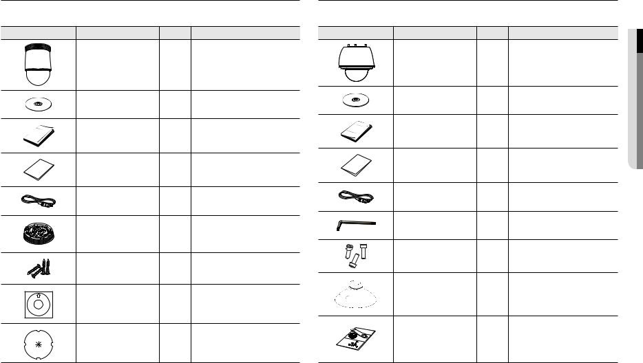
What’s Included (XNP-6320) |
|
|
|
Please check if your camera and accessories are all included in the product package. |
|||
(As for each sales country, accessories are not the same.) |
|
|
|
Appearance |
Item Name |
Quantity |
Description |
|
Camera |
1 |
|
|
Instruction book, |
1 |
|
|
Installer S/W CD |
|
|
|
|
|
|
|
Quick Guide |
1 |
|
|
(Optional) |
|
|
|
|
|
|
|
Warranty card |
1 |
|
|
(Optional) |
|
|
|
|
|
|
|
Cable for the testing monitor |
1 |
Used to test the camera connection to a portable |
|
display device |
||
|
|
|
|
|
Installation base |
1 |
If installing it indoors or in a ceiling housing |
|
Tapping Screw |
4 |
Used for installation on the ceiling |
|
Template |
1 |
Product installation guide |
|
Insulation Sheet |
1 |
Use when installing the camera at highly humid |
|
place |
||
|
|
|
|
What’s Included (XNP-6320H) |
|
|
|
Please check if your camera and accessories are all included in the product package. |
|||
(As for each sales country, accessories are not the same.) |
|
|
|
Appearance |
Item Name |
Quantity |
Description |
|
Camera |
1 |
|
|
Instruction book, |
1 |
|
|
Installer S/W CD |
|
|
|
|
|
|
|
Quick Guide |
1 |
|
|
(Optional) |
|
|
|
|
|
|
|
Warranty card |
1 |
|
|
(Optional) |
|
|
|
|
|
|
|
Cable for the testing monitor |
1 |
Used to test the camera connection to a portable |
|
display device |
||
|
|
|
|
|
Hex wrench |
1 |
Used for fixing the installation base after |
|
attaching it to the camera |
||
|
|
|
|
|
Hexagon screw |
3 |
Used for attaching the installation base to the |
|
camera |
||
|
|
|
|
|
Installation base |
1 |
Bracket for mounting outdoors |
|
Waterproofing accessory |
1 |
Install and use where there is high humidity. |
overview ●●
English _7
overview
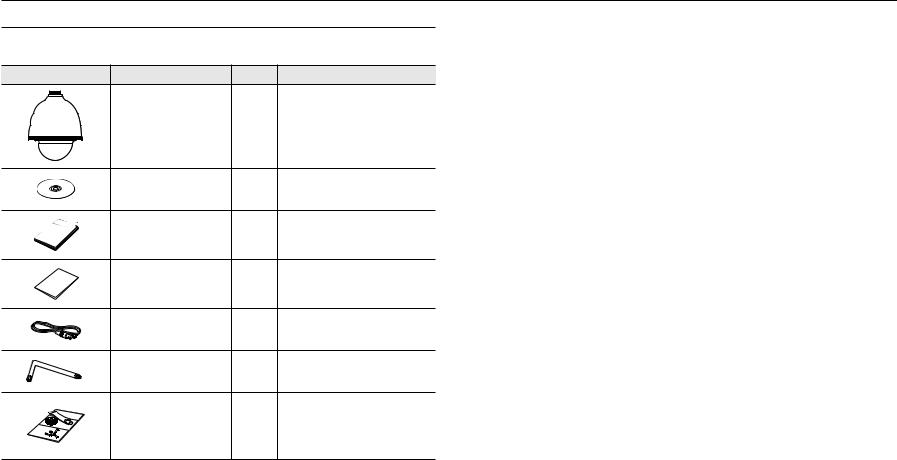
What’s Included (XNP-6320HS) |
|
|
|
Please check if your camera and accessories are all included in the product package. |
|||
(As for each sales country, accessories are not the same.) |
|
|
|
Appearance |
Item Name |
Quantity |
Description |
|
Camera |
1 |
|
|
Instruction book, |
1 |
|
|
Installer S/W CD |
|
|
|
|
|
|
|
Quick Guide |
1 |
|
|
(Optional) |
|
|
|
|
|
|
|
Warranty card |
1 |
|
|
(Optional) |
|
|
|
|
|
|
|
Cable for the testing monitor |
1 |
Used to test the camera connection to a portable |
|
display device |
||
|
|
|
|
|
Star-Shape wrench |
1 |
Used to fasten cover top and housing |
|
Waterproofing accessory |
1 |
Install and use where there is high humidity. |
8_ overview
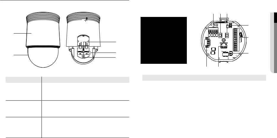
At a Glance (XNP-6320)
Appearance |
Inside |
|
|
|
|
a |
|
|
|
c |
|
b |
d |
|
e |
||
|
Item |
Description |
a Main unit |
Protects the internal PTZ mechanism from the direct sunlight or external impact. |
|
|
b Dome Cover |
Dome cover for the lens and unit protection. |
Port to connect the WiFi dongle.
c MICRO USB port You can check the installation video through the applications installed in the smartphone. Refer to “Connect to WiFi dongle” on page 13.
`` WiFi dongle and OTG adapter are sold separately.
Micro SD Memory Card |
Compartment for the Micro SD memory card. |
d Compartment |
|
e Reset Button |
Pressing and holding this button for about 5 seconds will reset all camera settings to the |
factory default. |
Bottom View of Installation |
Inner View of Installation Base |
Base |
|
|
a b c |
TXD+TXD-GND |
D- |
D+ |
AC- |
|
FG |
|
AC- |
|
h |
g |
2.COM 2.NO 2.NC |
1.NC |
1.NO |
1.COM |
GND |
IN4 |
IN3 |
GND |
IN2 |
IN1 |
d
e
f
Item |
Description |
a Communications Ports |
Used for RS-485 communications. |
|
|
b Audio Input Port |
Used to connect the audio input cable. |
|
|
c Audio Output Port |
Used to connect the audio output cable. |
|
|
d Video Out Port |
Analog video output port. (for installation) |
|
|
e Alarm I/O Port |
Used to connect the alarm I/O cable. |
|
|
f SwitchCommunications Setup |
Set communication protocol (RS-485) and indicate whether to terminate. |
g Network Connections |
Port for connection with the network using an Ethernet cable. |
|
|
h Power Port |
Used to connect the power. |
|
|
overview ●●
English _9

overview
At a Glance (XNP-6320H)
Appearance Inside
a |
|
b |
d |
c |
|
|
e |
|
f |
Item |
Description |
a Safety Cable |
The cable prevents the product from dropping during installation. |
b Housing |
Protects the internal PTZ mechanism from the direct sunlight, rain or external impact. |
c Dome Cover |
Dome cover for the lens and unit protection. |
|
Port to connect the WiFi dongle. |
d MICRO USB port |
You can check the installation video through the applications installed in the smartphone. |
Refer to “Connect to WiFi dongle” on page 13. |
|
|
` WiFi dongle and OTG adapter are sold separately. |
|
` |
Micro SD Memory Card |
Compartment for the Micro SD memory card. |
e Compartment |
|
f Reset Button |
Pressing and holding this button for about 5 seconds will reset all camera settings to the |
factory default. |
Bottom View of Installation |
Inner View of Installation Base |
Base |
|
|
a b c |
TXD+TXD-GND |
D- |
D+ |
AC- |
|
FG |
|
AC- |
|
h |
g |
2.COM 2.NO 2.NC |
1.NC |
1.NO |
1.COM |
GND |
IN4 |
IN3 |
GND |
IN2 |
IN1 |
d
e
f
Item |
Description |
a Communications Ports |
Used for RS-485 communications. |
|
|
b Audio Input Port |
Used to connect the audio input cable. |
|
|
c Audio Output Port |
Used to connect the audio output cable. |
|
|
d Video Out Port |
Analog video output port. (for installation) |
|
|
e Alarm I/O Port |
Used to connect the alarm I/O cable. |
|
|
f SwitchCommunications Setup |
Set communication protocol (RS-485) and indicate whether to terminate. |
g Network Connections |
Port for connection with the network using an Ethernet cable. |
|
|
h Power Port |
Used to connect the power. |
|
|
10_ overview
At a Glance (XNP-6320HS)
Appearance |
|
|
|
|
Inside |
|
|
|
|
|
|
|
|
a |
|
|
c |
b |
|
|
d |
|
e |
Item |
Description |
a Housing |
Protects the internal PTZ mechanism from direct sunlight, external shock, and corrosion. |
b Dome Cover |
Dome cover for the lens and unit protection. |
Port to connect the WiFi dongle.
c MICRO USB port You can check the installation video through the applications installed in the smartphone. Refer to “Connect to WiFi dongle” on page 13.
`` WiFi dongle and OTG adapter are sold separately.
Micro SD Memory Card |
Compartment for the Micro SD memory card. |
d Compartment |
|
e Reset Button |
Pressing and holding this button for about 5 seconds will reset all camera settings to the |
factory default. |
PCB inside
ab
c d e f
|
hg |
|
|
Item |
Description |
a Communications Ports |
Used for RS-485 communications. |
|
|
b Audio Input Port |
Used to connect the audio input cable. |
|
|
c Audio Output Port |
Used to connect the audio output cable. |
|
|
d Video Out Port |
Analog video output port. (for installation) |
|
|
e Alarm I/O Port |
Used to connect the alarm I/O cable. |
|
|
f SwitchCommunications Setup |
Set communication protocol (RS-485) and indicate whether to terminate. |
g Network Connections |
Port for connection with the network using an Ethernet cable. |
|
|
h Power Port |
Used to connect the power. |
|
|
overview ●●
English _11

installation & connection
`` Camera Wiring Interface Board
For the camera wiring, please refer to the picture below.
Refer to Control Signal Connection Diagram
D+ |
D- |
GND |
Audio |
|
|
|
IN |
Communications |
|
||
|
|
|
D+D-TXD+TXD-GND |
|
|
AC- |
|
|
|
FG |
|
|
|
AC- |
|
Power
Supply
ETHERNET
Power Input
Ground
Audio Video
OUT Output
2.COM 2.NO 2.NC |
1.NC |
1.NO |
1.COM |
GND |
IN4 |
IN3 |
GND |
IN2 |
IN1 |
Alarm
Alarm output
Alarm Input
JJ`` Select Normal Open in the setup menu.
-- The sensor input is activated during a short for contact type, or when it is at “Low” level for the active type.
`` Select Normal Close from the Setup menu.
-- The sensor input is activated when open for the contact type or when in high impedance state (open collector) for the active type.
`` The maximum capacity of the alarm output terminal is 30V DC/2A, 125V AC/0.5A and 250V AC/0.25A.
`` When connecting alarm input and output cables, be sure to connect one cable to each terminal respectively. `` To connect products over the camera’s capacity, please use an additional relay device.
`` If power and GND cables are connected inappropriately to the NC/NO or COM port, a fire or breakdown of equipment may occur.
Connecting with other Device
Preparing Adapter and Cable
JJ`` Connect the camera to the power adaptor. Then, plug the power cord of the adaptor to the wall outlet.
|
|
|
|
|
|
|
|
|
|
|
|
|
|
|
|
|
|
|
|
|
|
|
|
|
|
|
|
|
|
|
|
|
|
|
|
|
|
|
|
|
|
|
|
|
|
|
|
|
|
|
|
|
|
|
|
|
|
|
|
|
|
|
|
|
|
|
|
|
|
|
|
|
|
|
|
|
|
|
|
|
|
|
|
|
|
|
|
|
|
|
|
|
|
|
|
|
|
|
|
|
|
|
|
|
|
|
|
|
|
|
|
|
|
|
|
|
|
|
|
|
|
|
|
|
|
|
|
|
|
|
|
|
|
|
|
|
|
|
|
|
|
|
|
|
|
|
|
|
|
|
|
|
|
|
|
|
|
|
|
|
|
|
|
|
|
|
|
|
|
|
|
|
|
|
|
|
|
|
|
|
|
|
|
|
|
|
|
|
|
|
|
|
|
|
|
|
|
|
|
|
|
|
|
|
|
|
|
|
|
|
|
|
|
|
|
|
|
|
|
|
|
|
|
|
|
|
|
|
|
|
|
|
|
|
|
|
|
|
|
|
|
|
|
|
|
|
|
|
|
|
|
|
|
|
|
|
|
|
|
|
|
|
|
|
|
|
|
|
|
|
|
|
|
|
|
|
|
|
|
|
|
|
|
|
|
|
|
|
|
|
|
|
|
|
|
|
|
|
|
|
|
|
|
|
|
|
|
|
|
|
|
|
|
|
|
|
|
|
|
|
|
|
Check out the rated voltage and current before making connections. |
|
|||||||||||||||||
|
|
|
|
|
|
|
|
|
|
|
|
|
|
|
|
|
|
|
|
|
|
|
Rated Power |
|
Allowable Input Voltage |
||||||||||||
|
|
|
|
AC 24V |
|
AC22V~26V |
||||||||||||
|
|
|
|
PoE+ |
|
42.5Vdc~57Vdc |
||||||||||||
JJ`` If applied with both PoE+ and AC 24V power supplies, the device is powered from the first engaged supply. -- It is preferred to use single power supply of either one of PoE+ and AC 24V.
`` If connected to a switch device that provides PoE+ power, you don’t need to apply a power source of AC 24V supply. `` Make sure the PoE device suffices PoE+ (IEEE 802.3at) specifications.
-- If your device is connected to the switch with the standard of PoE (IEEE 802.3af), then go to the switch setup menu to “deactivate PoE”.
For further information on switch device, refer to the manufacturer’s manual. -- It is recommended to use a cable that complies with the PoE+ spec.
`` If you use a PoE+ as a power, the boot time may vary depending on a switch model (by channel) or a maker (as PoE+ connection time is included.).
`` The heater doesn’t work with the PoE+ power supply. (XNP-6320H/6320HS)
12_ installation & connection
Electrical Resistance of Copper Wire at [20°C (68°F)] |
|
|
|||
XNP-6320 |
|
|
|
|
|
|
Copper Wire Gauge (AWG) |
#20 |
#19 |
#18 |
#17 |
|
Resistance (Ω/m) |
0.0333 |
0.0264 |
0.021 |
0.0166 |
|
Recommended Distance (m) |
Less than 20 |
Less than 25 |
Less than 30 |
Less than 30 |
XNP-6320H/6320HS |
|
|
|
|
|
|
Copper Wire Gauge (AWG) |
#18 |
#17 |
#16 |
#15 |
|
Resistance (Ω/m) |
0.021 |
0.0166 |
0.0132 |
0.0104 |
|
Recommended Distance (m) |
Less than 15 |
Less than 20 |
Less than 25 |
Less than 30 |
` |
As shown in the table above, you may encounter a voltage-sag depending on the wire length. |
|
|||
` |
If you use an excessively long wire for camera connection, the camera may not work properly. |
|
|||
|
-- Camera Operating Voltage: AC 24V±10% |
|
|
|
|
|
-- Voltage drop measurements on the chart above may vary depending on the type and manufacture of the copper cable. |
||||
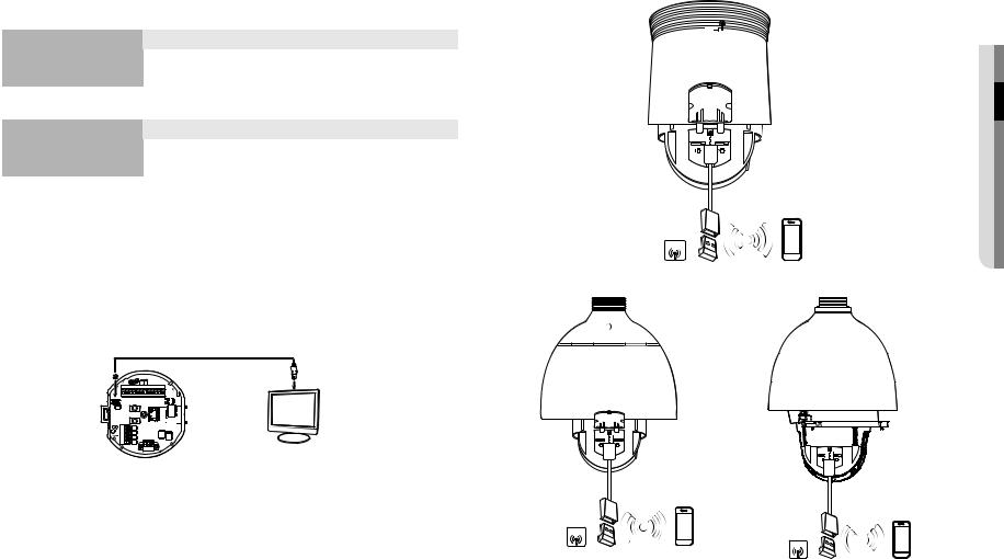
Ethernet Connection
Connect the Ethernet cable to the local network or to the Internet.
Connecting the installation monitor
Connect the cable to the camera’s rear video output terminal and the installation monitor’s video input terminal.
NO.2NC.2 |
NC.1COM.2 |
NO.COM1.1 |
GND |
IN3IN4 |
GND |
IN2 |
IN1 |
` |
AC-FGAC- |
Monitor |
|
The wiring varies depending on your monitor type and peripheral devices; please refer to the user manual for each device. |
|||
` |
|||
` |
Please make sure the monitor and camera are turned off when connecting them. |
||
` |
|||
JJ`` This product is a network camera that transfers video over a network; the video output terminal is used to set the imaging range of the camera at installation.
`` Using the terminal for monitoring purposes may cause problems such as degradation in video quality. `` It is not suitable for 24-hour monitoring using professional CRT monitors or TFT/LCD portable monitors. `` Use the network transfer screen for 24-hour monitoring and storage.
Connecting WiFi
WiFi dongle |
SOFTAP |
<XNP-6320>
WiFi dongle |
SOFTAP |
|
SOFTAP |
|
|
WiFi dongle |
|
|
<XNP-6320H> |
|
<XNP-6320HS> |
JJ`` The Micro USB out terminal of the product is provided for easier installation, and is not recommended for monitoring purposes.
connectionin&●sta●ationll
English _13

installation & connection
Camera Setup
1.Connect OTG adapter (5-pin) and WiFi dongle to the micro USB terminal.
Smartphone Setup
1.Install the Wisenet Installation application.
2.Select the camera SSID after turning on the WiFi.
3.Run the Wisenet Installation application.
4.When you log in to the camera, the video will be connected. (initial password: 4321)
`` The video will be played without being logged in during the initial connection.
5.You can adjust angle of view while watching the video through smartphone.
Recommended dongle manufacturer |
|
|
|
Manufacturer |
Model |
NETIS |
WF2123 n300 |
EDIMAX |
EW-7811Un |
IP Time |
N100mini |
TP-LINK |
TL-WN823N V1 |
ASUS |
USB-N13 |
NETGEAR |
WNA3100M |
Installation
Preparing & Installing Camera Bracket
For installation guidelines for brackets and housings, refer to the installation manual that is enclosed with the bracket or housing.
`` Available Bracket Models
|
|
|
|
Model |
Item |
XNP-6320 |
XNP-6320H/6320HS |
SHP-3701H |
Outdoor Housing |
|
- |
SHP-3701F |
Ceiling-mount Housing |
|
|
SBP-301HM3 |
Hanging Mount |
|
|
SBP-300WM1 |
Wall Mount |
|
|
SBP-300WM |
Yes |
|
|
|
|
||
SBP-300CM |
Ceiling Mount |
|
Yes |
SBP-300LM |
Parapet Mount |
|
|
|
|
||
SBP-300KM |
Corner Mount |
|
|
SBP-300PM |
Pole Mount |
|
|
MM`` See “Optional Accessories for Installation” for the appearance of each bracket (unbundled). (page 20)
14_ installation & connection

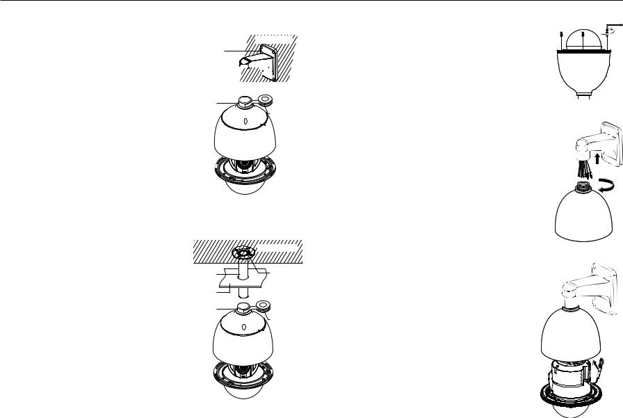
Installing by surface attachment (XNP-6320)
MM`` XNP-6320H/6320HS cannot be installed on the surface of a wall or ceiling.
`` Attaching Template & Installing installation base
1.Attach the provided template on the ceiling. Based on the template, drill a 86mm hole in the ceiling and arrange the wires through the hole.
2.Install installation base as shown.
3.Before installing the exposed bracket, open the hinged door at the bottom of the bracket as shown in the picture. Hold the knob on the hinged door to open it.
JJ`` In the case of installing the camera at highly humid place, install it on the ceiling after attaching the enclosed insulation sheet on the back of install base.
Template
Insulation Sheet
<Attaching insulatioin sheet>
`` Connect Terminal Wires
1.Connect the cables to the terminal block on the hinged door. Refer to “Camera Wiring Interface Board”. (page 12)
2.Once the wiring is complete, close the hinged door.
JJ`` Do not connect the camera to a power outlet until the installation is complete. Supplying power while the installation is in progress may cause fire or damage the product.
`` Connecting Camera Safety Cable and Attaching Camera
1. First, as shown in the left hand picture, pull out the safety cable from the base and then hook it to the mount. The safety cable is coiled inside the base.
`` To attach the camera to the mount, refer to the alignment guide marks as shown in the picture.
2. Carefully attach the camera to the mount following the alignment guide marks as shown in the picture.
Direction
Guides
Direction
Guides
Align the
Direction Guides
JJ`` Make sure to hook the camera’s safety cable to the mount before proceeding. Otherwise you may be exposed to serious injury caused by the camera falling.
connectionin&●sta●ationll
English _15

installation & connection
`` To attach or detach the camera, refer to the picture.
•• Attaching the Camera : Push up the camera unit and rotate it clockwise until it cannot be rotated anymore, as shown in the figure. After rotation, fasten the screws assembled to the install base.
< To Attach the Camera >
•• Detaching the Camera : Unfasten the screws as shown in the figure, push in the hook, and rotate it counterclockwise.
(The screws are not completely disassembled.)
When the hook does not rotate any more, pull down the camera unit and separate it.
< To Detach the Camera >
Installing by wall mount (XNP-6320H)
`` Fix the installation base with the bracket
1. Fix the base with the bracket by turning it clockwise.
2.As shown in the picture below, gently press and lift up the handle of the hinged door on the bottom of the installation base. Please refer to the “Camera Wiring Interface Board” on page 12, connect the wires.
JJ`` Do not connect the camera to a power outlet until the installation is complete. Supplying power while the installation is in progress may cause fire or damage the product.
MMCheck cable connection method and install.
`` Note that BUSHINGs are provided for outdoor installations where exposed to a moisture condition through the PIPE or MOUNT, install the HOUSING using the BUSHING to prevent moisture entering.
-- Apply grease of proper dose on the BUSHING before assembling, and run cables through each hole of the bushings. Use PINS to stop up empty holes having no cable running.
-- Assemble the BUSHING to the top side of HOUSING’s inside as shown in the diagram below. At the moment, apply pressure evenly on the BUSHING to secure it tightly to the HOUSING as shown in the diagram.
POWER POE+Ethernet cable
POWER(AC24V)(AC24V)
|
|
|
BUSH |
ETC CABLE |
|
BUSH |
||
|
||
|
|
|
|
HOUSING |
|
|
|
|
|
PIN |
|
BUSH |
BUSH |
|
|
HOUSING OR
MOUNT
INTERFACE
BUSHH |
16_ installation & connection

3. Connect the camera safety wire to the installation base. |
|
5. Attach Camera |
|
|
Rotate the mounted camera unit clockwise so that the reference indicators of top and bottom are as |
|
Safety Cable |
shown in the image on the right. |
|
|
connectionin&●sta●ationll
6. Secure Camera and Installation Base
As shown in the picture below, secure the installation base and camera using 3 hexagon screws.
4. Assemble Camera and Installation Base
Assemble the installation base and camera by matching the installation direction guides.
English _17
installation & connection
Notes for Waterproofing
`` Installing the unit on the wall by combining the outdoor housing and wall mount
1.Install the wall mount on the vertical wall. If the mount is installed on an inclined wall, moisture can penetrate inside the outdoor housing through the external cable.
2.Wrap the screw part of the housing with a sufficient amount of Teflon tape for assembly.
3.When separating the dome cover and fastening it to the housing frame, make sure that the gasket is not loosened to separate from the dome cover.
4.Install the wall mount adapter for waterproofing, and apply the silicon sealant between and around the wall and wall mount for sealing.
JJ`` Take particular caution to ensure that there is proper sealing if the installed side is not flat.
Concrete wall
Silicon sealant
Wall mount 


Screw |
|
unit |
Teflon tape |
 Dome gasket
`` Installing on the wall by combining the outdoor housing and ceiling mount adapter
1.Wrap the screw part of the housing with a sufficient amount of Teflon tape for assembly.
2.When separating the dome cover and fastening it to the housing frame, make sure that the gasket is not loosened to separate from the dome cover.
3.Install the ceiling mount adapter for waterproofing, and apply the silicon sealant between and around the wall and ceiling mount for sealing.
JJ`` Take particular caution to ensure that there is proper sealing if the installed side is not flat.
|
Concrete ceiling |
Ceiling mount |
Silicon |
adapter |
sealant |
Ceiling board |
|
Screw |
|
unit |
Teflon tape |
 Dome gasket
Installing by wall mount (XNP-6320HS)
1.Using a star-shape wrench, turn the three screws counterclockwise to remove the housing.
2. Attach the housing to the bracket by turning it clockwise.
3. Attach the camera’s safety cable to the housing.
18_ installation & connection

4.Referring to “camera wiring interface Board” on page 12, connect the wiring to the PCB terminal block.
JJ `` Apply power to the product at the final stage. If the power is turned on during installation, there is a risk of damage or fire.
MMCheck cable connection method and install.
`` Note that BUSHINGs are provided for outdoor installations where exposed to a moisture condition through the PIPE or MOUNT, install the HOUSING using the BUSHING to prevent moisture entering.
-- Apply grease of proper dose on the BUSHING before assembling, and run cables through each hole of the bushings. Use PINS to stop up empty holes having no cable running.
-- Assemble the BUSHING to the top side of HOUSING’s inside as shown in the diagram below. At the moment, apply pressure evenly on the BUSHING to secure it tightly to the HOUSING as shown in the diagram.
BUSH 
BUSH
POWER POE+Ethernet cable
POWER(AC24V)(AC24V)
ETC CABLE
BUSH HOUSING
PIN
BUSH
5. Align the holes of the camera body and the housing and turn them slightly.
6.Using a star-shpe wrench, turn the three screws clockwise to tighten the housing.
connectionin&●sta●ationll
English _19

installation & connection
Notes for Waterproofing
`` Installing the unit on the wall by combining the outdoor housing and wall mount
1.Install the wall mount on the vertical wall. If the mount is installed on an inclined wall, moisture can penetrate inside the outdoor housing through the external cable.
2.Wrap the screw part of the housing with a sufficient amount of Teflon tape for assembly.
3.When separating the dome cover and fastening it to the housing frame, make sure that the gasket is not loosened to separate from the dome cover.
4.Install the wall mount adapter for waterproofing, and apply the silicon sealant between and around the wall and wall mount for sealing.
JJ`` Take particular caution to ensure that there is proper sealing if the installed side is not flat.
Concrete wall
Silicon sealant
Wall mount 


Screw |
Teflon tape |
unit |

 Dome gasket
`` Installing on the wall by combining the outdoor housing and ceiling mount adapter
1.Wrap the screw part of the housing with a sufficient amount of Teflon tape for assembly.
2.When separating the dome cover and fastening it to the housing frame, make sure that the gasket is not loosened to separate from the dome cover.
3.Install the ceiling mount adapter for waterproofing, and apply the silicon sealant between and around the wall and ceiling mount for sealing.
JJ`` Take particular caution to ensure that there is proper sealing if the installed side is not flat.
|
Concrete ceiling |
Ceiling mount |
Silicon |
adapter |
sealant |
Ceiling board |
|
Screw |
Teflon tape |
unit |

 Dome gasket
Optional Accessories for Installation
For your easier installation, you can purchase appropriate optional accessories available.
1.If installing the camera on the wall
•• Wall mount (SBP-300WM1)
•• Wall mount (SBP-300WM)
2.If installing the camera on the ceiling
•• Ceiling Mount (SBP-300CM)
3. If installing the wall mount (SBP-300WM/SBP-300WM1) on an at least 80mm-long cylinder
•• Pole Mount (SBP-300PM)
20_ installation & connection
4.If installing the wall mount (SBP-300WM/SBP-300WM1) on a corner of the wall
•• Corner Mount (SBP-300KM)
5.If installing on a building rooftop
•• Parapet Mount (SBP-300LM)
6.If installing XNP-6320 outdoors
•• Outdoor Housing (SHP-3701H)
7.If installing XNP-6320 on a ceiling as built-in component
•• Flush-Mount Indoor Housing for PTZ Dome Camera (SHP-3701F)
8.If installing XNP-6320 in the wall mount or ceiling mount
•• Hanging Mount (SBP-301HM3)
connectionin&●sta●ationll
English _21
installation & connection
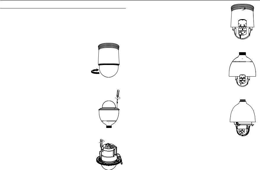
Inserting/Removing a Micro SD Memory Card
JJ`` Disconnect the power cable from the camera before inserting the Micro SD memory card.
`` Do not insert the Micro SD memory card while it’s upside down by force. Otherwise, it may damage the Micro SD memory card.
`` When it rains or the humidity is high, insertion or ejection of a Micro SD card is not recommended.
`` Disassembly of the product cover should be finished within 5 minutes, or there will be the risk of internal dew condensation.
Inserting a Micro SD Memory Card
1. Open the cover in the rear of the camera. (XNP-6320)
<XNP-6320>
Using the screw driver, loosen 3 screws by turning them counterclockwise and separate the dome cover. (XNP-6320H/6320HS)
<XNP-6320H>
<XNP-6320HS>
2. Push the Micro SD memory card in the direction of the arrow shown in the diagram.
JJ`` Do not insert the Micro SD memory card while it’s upside down by force. Otherwise, it may damage the Micro SD memory card.
<XNP-6320>
<XNP-6320H>
<XNP-6320HS>
22_ installation & connection
Removing a Micro SD Memory Card
Gently press down on the exposed end of the memory card as shown in the diagram to eject the memory card from the slot.
JJ`` Pressing too hard on the Micro SD memory card can cause the card to shoot out uncontrollably from the slot when released.
`` Before removing the micro SD memory card, turn off the camera or set the device to <Off> in <Storage> and press the [Apply] button. (Page 55)
`` If you turn off the camera or remove the Micro SD memory card that contains data from the product, the data may be lost or damaged.
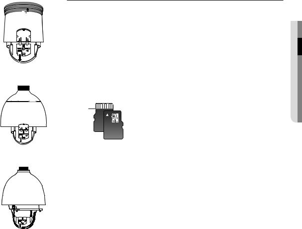
Memory Card Information (Not Included)
|
What is a memory card? |
|
The memory card is an external data storage device that has been developed to offer an entirely new way to |
|
record and share video, audio, and text data using digital devices. |
|
Selecting a memory card that’s suitable for you |
|
Your camera supports Micro SD/SDHC/SDXC memory cards. |
|
You may, however, experience compatibility issues depending on the model and make of the memory card. |
|
The following types of memory cards from the following manufacturers are recommended for this camera. |
<XNP-6320> |
-- Manufacturer : SanDisk, Transcend |
-- Product family : High endurance |
|
|
It is recommended to use a 16GB to 256GB (MLC type) memory card for this camera. |
|
Playback performance can be affected depending on the speed of memory card. |
|
Memory Card Components |
|
Contacts |
connectionin&●sta●ationll
Micro SD/SDHC/SDXC
<XNP-6320H>
<XNP-6320HS>
English _23
network connection and setup
You can set up the network settings according to your network configurations.
Connecting the Camera Directly to Local Area Networking
Connecting to the camera from a local PC in the LAN
1.Launch an Internet browser on the local PC.
2.Enter the IP address of the camera in the address bar of the browser.
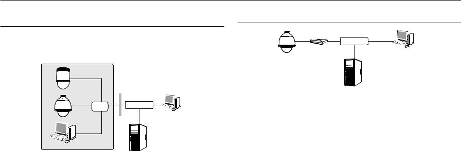
Connecting the Camera Directly to a DHCP Based DSL/Cable Modem
INTERNET 
DSL/Cable Modem |
External Remote PC |
|
Camera
Camera |
Switch |
Camera |
INTERNET 
External Remote PC
Local PC |
DDNS Server |
(Data Center, KOREA) |
<Local Network>
MM`` A remote PC in an external Internet out of the LAN network may not be able to connect to the camera installed in the intranet if the port-forwarding is not properly set or a firewall is set.
In this case, to resolve the problem, contact your network administrator.
`` In the IP installer, you can use the initial password, “4321” to set IP Address, Subnet Mask, Gateway, HTTP Port, VNP Port, IP type. After changing the network interface, for better security, access the web viewer and change the password.
`` By factory default, the IP address will be assigned from the DHCP server automatically. If there is no DHCP server available, the IP address will be set to 192.168.1.100.
To change the IP address, use the IP Installer.
For further details on IP Installer use, refer to “Static IP Setup”. (Page 26)
DDNS Server
(Data Center, KOREA)
1.Connect the user PC directly with the network camera.
2.Run the IP Installer and change the IP address of the camera so that you can use the web browser on your desktop to connect to the Internet.
3.Use the Internet browser to connect to the web viewer.
4.Move to [Setup] page.
5.Move to [Network] – [DDNS] and configure the DDNS settings.
6.Move to [Basic] – [IP & Port], and set the IP type to [DHCP].
7.Connect the camera, which was removed from your PC, directly to the modem.
8.Restart the camera.
MM`` For configuring the DDNS settings, refer to “DDNS”. (page 50)
`` For registering the DDNS settings, refer to “Registering with DDNS”. (page 51) `` Refer to “IP & Port” for how to setup IP. (page 40)
24_ network connection and setup
Connecting the Camera Directly to a PPPoE Modem
INTERNET 
PPPoE Modem |
External Remote PC |
|
Camera
DDNS Server
(Data Center, KOREA)
1.Connect the user PC directly with the network camera.
2.Run the IP Installer and change the IP address of the camera so that you can use the web browser on your desktop to connect to the Internet.
3.Use the Internet browser to connect to the web viewer.
4.Move to [Setup] page.
5.Move to [Network] – [DDNS] and configure the DDNS settings.
6.Move to [Basic] – [IP & Port] Setup Page, set the IP type to [PPPoE], and enter the network service’s ID and password.
7.Connect the camera, which was removed from your PC, directly to the modem.
8.Restart the camera.
MM`` For configuring the DDNS settings, refer to “DDNS”. (page 50)
`` For registering the DDNS settings, refer to “Registering with DDNS”. (page 51) `` Refer to “IP & Port” for how to setup IP. (page 40)
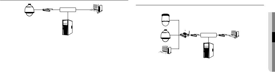
Connecting the Camera to a Broadband Router with the PPPoE/Cable Modem
This is for a small network environment such as homes, SOHO and ordinary shops.
Camera |
Camera |
INTERNET
Broadband |
PPPoE or |
Cable Modem |
|
Router |
|
PPPoE or |
External Remote PC |
Cable Modem |
DDNS Server
 (Data Center, KOREA) Local PC
Configuring the network settings of the local PC connected to a Broadband Router
Configuring the network settings of the local PC connected to a Broadband Router, follow the instructions below.
•• Select : <Network> <Properties> <Local Area Connection> <General> <Properties> <Internet Protocol (TCP/IP)> <Properties> <Obtain an IP address automatically> or <Use the following IP address>.
•• Follow the instructions below if you select <Use the following IP address>:
ex1) If the address (LAN IP) of the Broadband Router is 192.168.1.1 IP address : 192.168.1.100
Subnet Mask : 255.255.255.0
Default Gateway : 192.168.1.1
ex2) If the address (LAN IP) of the Broadband Router is 192.168.0.1 IP address : 192.168.0.100
Subnet Mask : 255.255.255.0
Default Gateway : 192.168.0.1
ex3) If the address (LAN IP) of the Broadband Router is 192.168.xxx.1 IP address : 192.168.xxx.100
Subnet Mask : 255.255.255.0 Default Gateway : 192.168.xxx.1
MM`` For the address of the Broadband Router, refer to the product’s documentation.
`` For more information about port forwarding of the broadband router, refer to “Port Range Forward (Port Mapping) Setup”. (Page 28)
upd
networan connection●● k
English _25

network connection and setup
Buttons used in IP Installer
a b c d e f g
|
|
|
|
|
|
|
|
|
|
|
|
|
|
|
|
|
|
|
|
|
|
|
|
|
|
|
|
|
|
|
|
|
|
|
|
|
|
|
|
|
|
|
|
|
|
|
|
|
|
|
|
|
|
|
|
|
|
|
|
|
|
|
|
|
|
|
|
|
|
|
|
|
|
|
|
|
|
|
|
|
|
|
|
|
|
|
|
|
|
|
hi |
|
j k |
l m |
|||||||
|
|
|
|
|
|
|
|
|
|
|
|
|
|
|
|
|
Item |
|
|
|
|
|
|
|
Description |
||||||||
a Device Name |
|
Model name of the connected camera. |
|
|
|
|
||||||||||
|
Click the column to sort the list by model name. |
|
|
|
|
|||||||||||
|
|
|
|
However, search will be stopped if clicked during the search. |
||||||||||||
b Alias |
|
This function is not currently implemented. |
|
|
|
|
||||||||||
c Mode |
|
Displays either <Static>, <Dynamic> or <PPPoE> for the current network connection |
||||||||||||||
|
status. |
|
|
|
|
|||||||||||
d MAC(Ethernet) Address |
|
Ethernet address for the connected camera. |
|
|
|
|
||||||||||
|
Click the column to sort the list by Ethernet address. |
|||||||||||||||
|
|
|
|
However, search will be stopped if clicked during the search. |
||||||||||||
e IP Address |
|
IP address. |
|
|
|
|
||||||||||
|
Click the column to sort the list by IP address. |
|
|
|
|
|||||||||||
|
|
|
|
However, search will be stopped if clicked during the search. |
||||||||||||
f Protocol |
|
Network setting for the camera. |
|
|
|
|
||||||||||
|
The factory default is “IPv4”. |
|
|
|
|
|||||||||||
|
|
|
|
Cameras with the IPv6 setting will be displayed “IPv6”. |
||||||||||||
g URL |
|
DDNS URL address enabling access from the external Internet. |
||||||||||||||
|
However, this will be replaced with the <IP Address> of the camera if DDNS registration |
|||||||||||||||
|
|
|
|
has failed. |
|
|
|
|
||||||||
h IPv4 |
|
Scans for cameras with the IPv4 setting. |
|
|
|
|
||||||||||
Item |
Description |
i IPv6 |
Scans for cameras with the IPv6 setting. |
Activated in an IPv6 compliant environment only. |
|
j Search |
Scans for cameras that are currently connected to the network. |
However, this button will be grayed out if neither IPv4 nor IPv6 is checked. |
|
k Auto Set |
The IP Installer automatically configures the network settings. |
l Manual Set |
You should configure the network settings manually. |
m Exit |
Exits the IP Installer program. |
MM`` For the IP installer, use only the installer version provided in the installation CD or use the latest one if available. You can download the latest version from the Hanwha Techwin web site.
`` If the supporting OS is Windows 8.1, it is recommended that you use the Wisenet Device Manager instead of the IP Wisenet. The Wisenet Device Manager Program can be downloaded by visiting the Hanwha Techwin website (http://www.hanwhasecurity.com) under the menu <Customer Support> - <Technical Guides> - <Online Tool>.
Static IP Setup
Manual Network Setup
Run <IP Installer_v2.XX.exe> to display the camera search list.
At the initial startup, both [Auto Set] and [Manual Set] will be grayed out.
MM`` For cameras found with the IPv6 setting, these buttons will be grayed out as the cameras do not support this function.
1.Select a camera in the search list.
Check the MAC address of the camera on the camera’s label. Both the [Auto Set] and [Manual Set] buttons will be activated.
2.Click [Manual Set].
The Manual Setting dialog appears.
<IP Address>, <Subnet Mask>, <Gateway>, <HTTP Port>, and <VNP Port> of the camera are displayed in the preset values.
3.In the <Address> pane, provide the necessary information.
•• MAC (Ethernet) Address : The MAC address imprinted on the camera label is automatically displayed and requires no user setting.
MM`` IP related parameters can be set only when DHCP is not checked.
26_ network connection and setup
 Loading...