


QNV-6070R

NETWORK CAMERA
User Manual
QND-6070R/QNO-6070R/QNV-6070R

Copyright
©2016
Hanwha Techwin
Co., Ltd. All r ights reser ved.
Trademark
Each of trademarks herein is registered. The name of this product and other trademarks mentioned in this manual are the registered trademark of their
respective company.
Restriction
Copyright of this document is reserved. Under no circumstances, this document shall be reproduced, distributed or changed, partially or wholly, without
formal authorization.
Disclaimer
Hanwha Techwin
makes the best to verify the integrity and correctness of the contents in this document, but no formal guarantee shall be
provided. Use of this document and the subsequent results shall be entirely on the user’s own responsibility.
Hanwha Techwin
reserves the
right to change the contents of this document without prior notice.
Design and specications are subject to change without prior notice.
The initial administrator ID is “admin” and the password should be set when logging in for the rst time.
Please change your password every three months to safely protect personal information and to prevent the damage of the information
theft.
Please, take note that it’s a user’s responsibility for the security and any other problems caused by mismanaging a password.
Network Camera
User Manual
English _3
●● OVERVIEW
IMPORTANT SAFETY INSTRUCTIONS
1. Read these instructions.
2. Keep these instructions.
3. Heed all warnings.
4. Follow all instructions.
5. Do not use this apparatus near water.
6. Clean the contaminated area on the product surface with a soft, dry cloth or a damp cloth.
(Do not use a detergent or cosmetic products that contain alcohol, solvents or surfactants or oil constituents
as they may deform or cause damage to the product.)
7. Do not block any ventilation openings, Install in accordance with the manufacturer’s instructions.
8. Do not install near any heat sources such as radiators, heat registers, stoves, or other apparatus (including
amplifiers) that produce heat.
9. Do not defeat the safety purpose of the polarized or grounding-type plug. A polarized plug has two blades
with one wider than the other. A grounding type plug has two blades and a third grounding prong. The wide
blade or the third prong are provided for your safety. If the provided plug does not fit into your outlet, consult
an electrician for replacement of the obsolete outlet.
10. Protect the power cord from being walked on or pinched particularly at plugs, convenience receptacles, and
the point where they exit from the apparatus.
11. Only use attachments/ accessories specified by the manufacturer.
12. Use only with the cart, stand, tripod, bracket, or table specified by the manufacturer,
or sold with the apparatus. When a cart is used, use caution when moving the cart/
apparatus combination to avoid injury from tip-over.
13. Unplug this apparatus during lighting storms or when unused for long periods of time.
14. Refer all servicing to qualified service personnel. Servicing is required when the apparatus
has been damaged in any way, such as power-supply cord or plug is damaged, liquid has
been spilled or objects have fallen into the apparatus, the apparatus has been exposed to rain or moisture,
does not operate normally, or has been dropped.
15. This product is intended to be supplied by a Listed Power Supply Unit marked “Class 2” or “LPS” and rated
from 12 Vdc, min. current for each product.
WARNING
TO REDUCE THE RISK OF FIRE OR ELECTRIC SHOCK, DO NOT EXPOSE THIS PRODUCT
TO RAIN OR MOISTURE. DO NOT INSERT ANY METALLIC OBJECT THROUGH THE
VENTILATION GRILLS OR OTHER OPENNINGS ON THE EQUIPMENT.
Apparatus shall not be exposed to dripping or splashing and that no objects filled with liquids,
such as vases, shall be placed on the apparatus.
To prevent injury, this apparatus must be securely attached to the Wall/ceiling in accordance
with the installation instructions.
CAUTION
CAUTION
RISK OF ELECTRIC SHOCK.
DO NOT OPEN
CAUTION
: TO REDUCE THE RISK OF ELECTRIC SHOCK.
DO NOT REMOVE COVER (OR BACK).
NO USER SERVICEABLE PARTS INSIDE.
REFER SERVICING TO QUALIFIED SERVICE PERSONNEL.
EXPLANATION OF GRAPHICAL SYMBOLS
The lightning flash with arrowhead symbol, within an equilateral triangle, is
intended to alert the user to the presence of “dangerous voltage” within the
product’s enclosure that may be of sufficient magnitude to constitute a risk of
electric shock to persons.
The exclamation point within an equilateral triangle is intended to alert the user to
the presence of important operating and maintenance (servicing) instructions in
the literature accompanying the product.
overview

overview
4_ overview
Class construction
An apparatus with CLASS construction shall be connected to a MAINS socket outlet with a
protective earthing connection.
Battery
Batteries(battery pack or batteries installed) shall not be exposed to excessive heat such as
sunshine, fire or the like.
Disconnection Device
Disconnect the main plug from the apparatus, if it’s defected. And please call a repair man in
your location.
When used outside of the U.S., it may be used HAR code with fittings of an approved
agency is employed.
CAUTION
Risk of explosion if battery is replaced by an incorrect type.
Dispose of used batteries according to the instructions.
These servicing instructions are for use by qualified service personnel only.
To reduce the risk of electric shock do not perform any servicing other than that contained in
the operating instructions unless you are qualified to do so.
Please use the input power with just one camera and other devices must not be connected.
The ITE is to be connected only to PoE networks without routing to the outside plant.
Please read the following recommended safety precautions carefully.
y
Do not place this apparatus on an uneven surface.
y
Do not install on a surface where it is exposed to direct sunlight, near heating equipment or
heavy cold area.
y
Do not place this apparatus near conductive material.
y
Do not attempt to service this apparatus yourself.
y
Do not place a glass of water on the product.
y
Do not install near any magnetic sources.
y
Do not block any ventilation openings.
y
Do not place heavy items on the product.
y
Please wear protective gloves when installing/removing the camera.
The high temperature of the product surface may cause a burn.
User’s Manual is a guidance book for how to use the products.
The meaning of the symbols are shown below.
y
Reference : In case of providing information for helping of product’s usages
y
Notice : If there’s any possibility to occur any damages for the goods and human caused by
not following the instruction
Please read this manual for the safety before using of goods and keep it in the safe place.

English _5
●● OVERVIEW
CONTENTS
overview
3
3 Important Safety Instructions
6 Product Features
6 Recommended PC Specifications
6 Recommended Micro SD/SDHC/SDXC
Memory Card Specifications
6 NAS recommended specs
7 What’s Included
8 At a Glance (QND-6070R)
10 At a Glance (QNO-6070R)
11 At a Glance (QNV-6070R)
installation & connection
13
13 Installation (QND-6070R)
14 Installation (QNO-6070R)
15 Installation (QNV-6070R)
18 Inserting/Removing a Micro SD Memory
Card
20 Memory Card Information (Not Included)
20 Connecting with other Device
network connection and
setup
24
24 Connecting the Camera Directly to Local
Area Networking
24 Connecting the Camera Directly to a DHCP
Based DSL/Cable Modem
25 Connecting the Camera Directly to a
PPPoE Modem
25 Connecting the Camera to a Broadband
Router with the PPPoE/Cable Modem
26 Buttons used in IP Installer
26 Static IP Setup
28 Dynamic IP Setup
28 Port Range Forward (Port Mapping) Setup
29 Connecting to the Camera from a Shared
Local PC
29 Connecting to the Camera from a Remote
PC via the Internet
web viewer
30
30 Connecting to the Camera
31 Password setting
31 Login
31 Plug-in support specifications for each
browser
32 Installing WebViewer Plugin
32 Using a Plug-in Free Webviewer
32 Using the Live Screen (Plug-in Free
Webviewer)
33 Using the Live Screen (Plug-in Webviewer)
35 Playing the recorded video (Plug-in Free
Webviewer)
37 Playing the recorded video (Plug-in
Webviewer)
setup screen
40
40 Setup
40 Basic Setup
44 Audio & Video setup
49 Network Setup
52 Event Setup
54 NAS (Network Attached Storage) guide
59 System Setup
appendix
61
61 Specification
63 Product Overview
64 Troubleshooting
65 Open Source Announcement

overview
6_ overview
PRODUCT FEATURES
• Dustproof/Waterproof (IP66) (QNO-6070R/QNV-6070R)
The dustproof and waterproof design makes you feel at ease when installing the product outdoors or exposing
it to rain.
• IR mode
If the IR indicator turns on, the product switches to the IR mode for preventing an object from being too bright,
which helps you identify the object in near distance.
• Supports 2 megapixel resolution videos
• Multi-Streaming
This network camera can display videos in different resolutions and qualities simultaneously using different
CODECs.
• Web Browser-based Monitoring
Using the Internet web browser to display the image in a local network environment.
• Alarm
When an event occurs, video is either sent to the email address registered by the user, sent to the FTP server,
saved in a Micro SD card or NAS, or a signal is sent to the alert output terminal.
• Tampering Detection
Detects tempering attempts on video monitoring.
• Defocus detection function
Detects the defocus phenomenon of the camera lens.
• Motion Detection
Detects motion from the camera’s video input.
• Auto Detection of Disconnected Network
Detects network disconnection before triggering an event.
• ONVIF Compliance
This product supports ONVIF Profile S&G.
For more information, refer to www.onvif.org.
RECOMMENDED PC SPECIFICATIONS
• CPU : Intel(R) Core(TM) i7 3.4 GHz or higher
• Supported OS : Windows 7, 8.1, 10, Mac OS X 10.9, 10.10, 10.11
• Plug-in free web viewer
Supported web browsers : Google Chrome 47, MS Edge 20
• Plug-in Webviewer
Supported web browsers : MS Explorer 11, Mozilla Firefox 43, Apple Safari 9
※
Mac OS X only
• VGA : PCIe 256MB GDDR3 video graphics card or higher
RECOMMENDED MICRO SD/SDHC/SDXC MEMORY CARD
SPECIFICATIONS
• Recommended capacity : 4GB ~ 128GB (uhs-1 class)
• For your camera, we recommend you use a memory card from the following manufacturers:
Micro SD/SDHC/SDXC Memory Card : Sandisk, Transcend
NAS RECOMMENDED SPECS
• Recommended capacity : 200GB or higher is recommended.
• Simultaneous access : One unit of NAS can accept a maximum of sixteen camera accesses.
• For this camera, you are recommended to use a NAS with the following manufacturer’s specs.
Recommended products Available sizes
Netgear NAS A maximum of 16 cameras can access simultaneously.
Synology NAS A maximum of 16 cameras can access simultaneously.
J
`
When you use Netgear’s NAS equipment, do not allocate the capacity for use.
`
If you use NAS equipment for purposes other than video saving, the number of accessible cameras may be reduced.
English _7
●● OVERVIEW
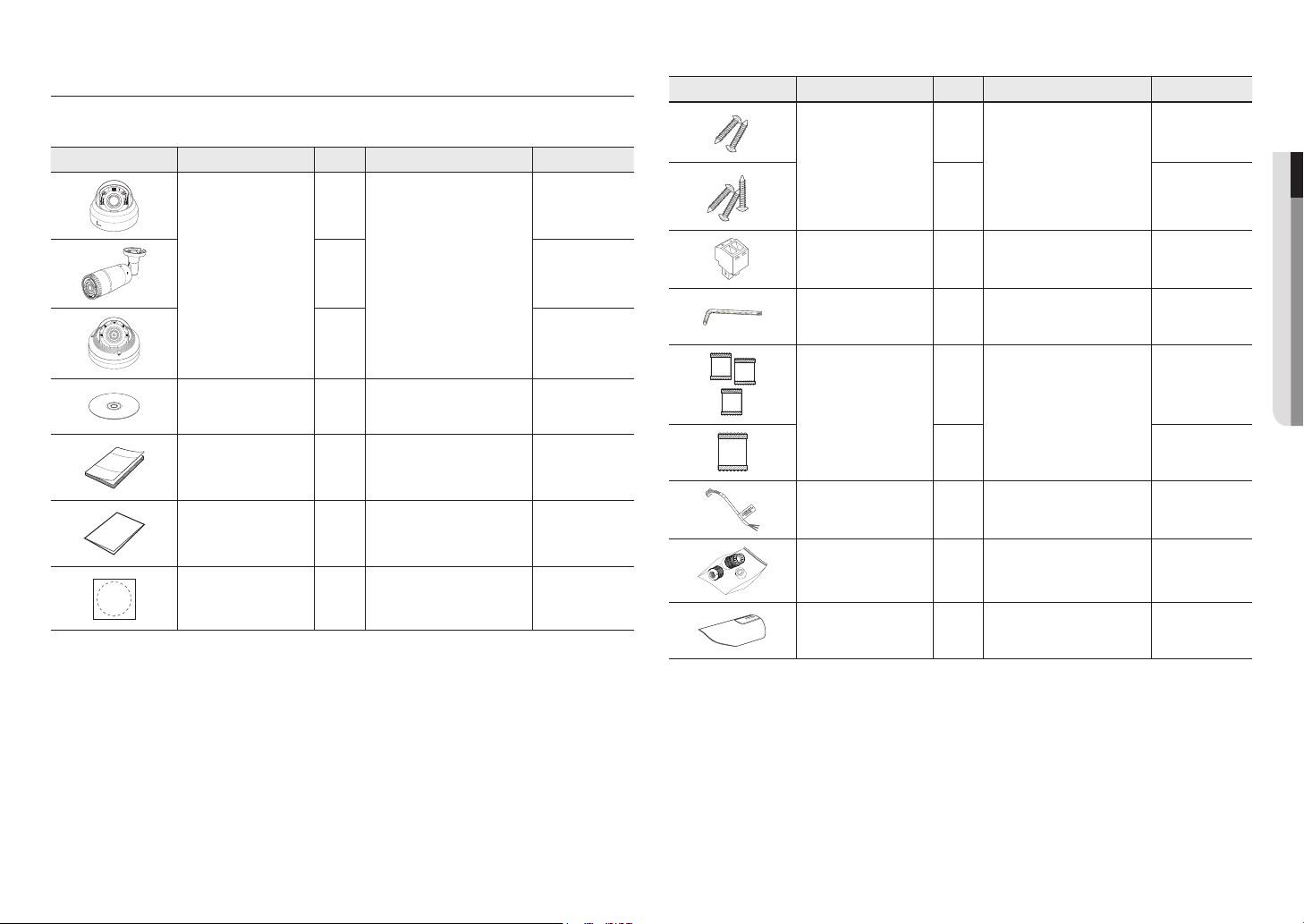
WHAT’S INCLUDED
Please check if your camera and accessories are all included in the product package.
(As for each sales country, accessories are not the same.)
Appearance Item Name Quantity Description Model Name
Camera
1
QND-6070R
1
QNO-6070R
1
QNV-6070R
Instruction book,
Installer S/W CD
1
QND-6070R/
QNO-6070R/
QNV-6070R
Quick Guide
(Optional)
1
QND-6070R/
QNO-6070R/
QNV-6070R
Warranty card
(Optional)
1
QND-6070R/
QNO-6070R/
QNV-6070R
Template
1
Product installation guide
QND-6070R/
QNO-6070R/
QNV-6070R
Appearance Item Name Quantity Description Model Name
Tapping Screw
2
Used for installation on the wall or
ceiling
QND-6070R
3
QNO-6070R/
QNV-6070R
Power Terminal Block
1
Plugged in the power plug
QND-6070R/
QNV-6070R
L Wrench
1
Used to control the direction of the
camera / Used to remove and replace
the dome cover
QNO-6070R/
QNV-6070R
Card-type moisture absorbent
3
Attached when installed.
QNO-6070R
1
QNV-6070R
Alarm cable
1
Used when connecting to an alarm QND-6070R
RJ45 waterproof accessory
1
Used to install in humid places QNO-6070R
Sunshield
1
It protects the camera from the direct
sunlight.
QNO-6070R
overview
8_ overview
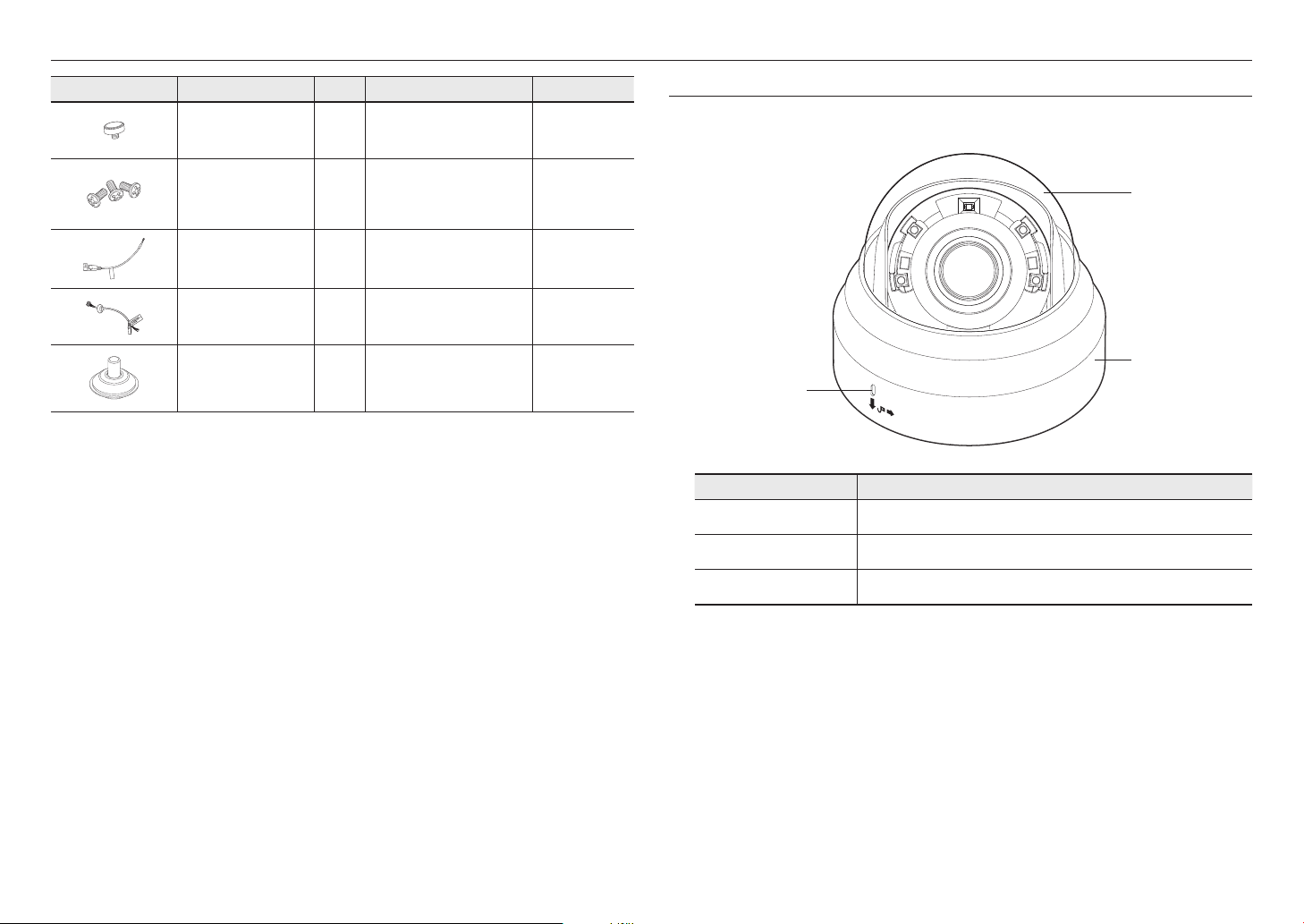
AT A GLANCE (QND-6070R)
Appearance
Item Description
a
Dome cover
Case cover used to protect the lens and the main unit.
b
Camera Case
Housing part that covers the camera body.
c
Microphone hole
Microphone is embedded.
Appearance Item Name Quantity Description Model Name
Sunshield Hold
1
It fixes the sunshield with the camera. QNO-6070R
Machine Screws
3
Used for assembling the dome case
when installing the product on the
pipe, wall mount, etc. or blocking a
hole.
QNV-6070R
CAUTION: Be ware of the
Rated Voltage and Polarity
of the power connection.
Power Cable
1
Used to plug into the power port QNV-6070R
Audio/alarm cable
1
Used to connect with the audio and
alarm port
QNV-6070R
Cable bush
1
Used to connect the LAN cable with a
diameter of Ø7~8.5.
QNV-6070R
a
b
c
English _9
●● OVERVIEW
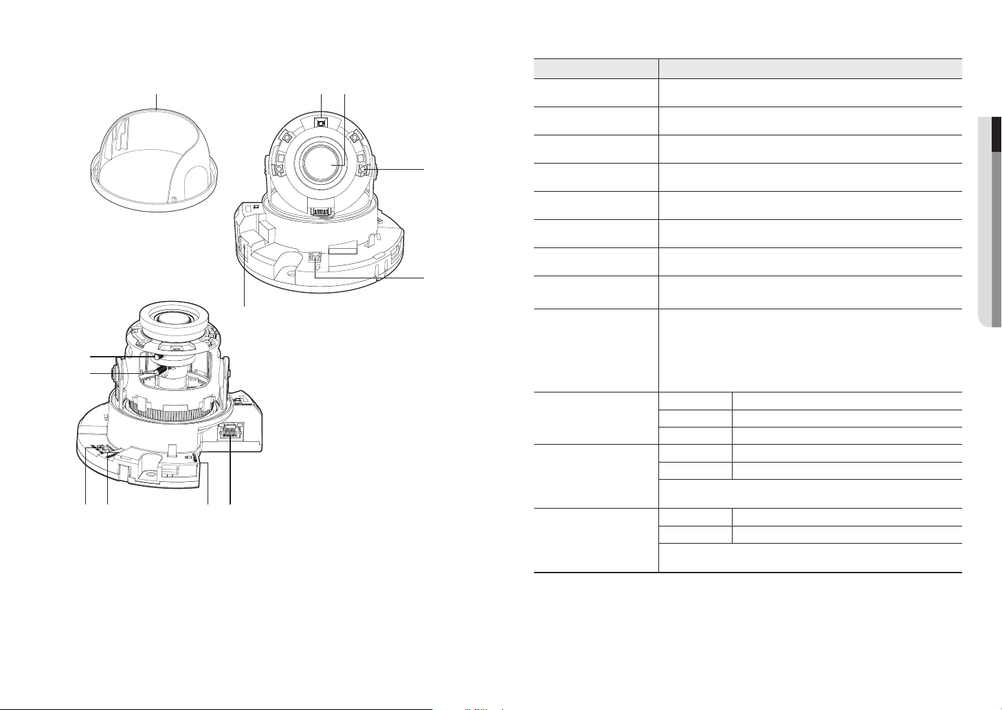
Components
Item Description
a
Inside cover Protective cover for the main body.
b
Illumination Sensor Detects incoming light to control the IR LED.
c
Lens Lens for the camera.
d
IR LED These infrared LED’s are controlled by the illumination sensor.
e
Power Port Port for power terminal block.
f
Microphone hole Microphone is embedded.
g
Network Port Used to connect the PoE or Ethernet cable for network connection.
h
Micro SD Memory Card
Compartment
Compartment for the Micro SD memory card.
i
Reset Button
The button restores all camera settings to the factory default.
Press and hold for about 5 seconds to reboot the system.
J
If you reset the camera, the network settings will be adjusted so that DHCP can be
enabled. If there is no DHCP server in the network, you must run the IP Installer
program to change the basic network settings such as IP address, Subnet mask,
Gateway, etc., before you can connect to the network.
j
Alarm I/O Port
ARM-IN Used to connect the alarm input sensor or external day/night sensor.
ARM-OUT Used to connect the alarm output signal.
GND These are common ports to connect alarm input/output signals.
k
Zoom control lever
T Zoom in (Tele)
W Zoom out (Wide)
Release the lever and move it to left or right to zoom the lens in or out.
Turn the lever clockwise to fix the adjusted position to prevent it from being moved.
l
Focus control lever
N Focusing on a near object (Near)
F Focusing on a far object (Far)
Release the lever and move it to left or right to adjust the lens focus.
Turn the lever clockwise to fix the adjusted position to prevent it from being moved.
ij gh
a
NETWORK
ACT
LiNK
e
d
cb
f
k
l
overview
10_ overview
Components
Item Description
a
Power Port Used to plug the power cable.
b
Alarm I/O Port
ARM-OUT Used to connect the alarm output signal.
GND These are common ports to connect alarm input/output signals.
ARM-IN Used to connect the alarm input sensor or external day/night sensor.
c
Network Port Used to connect the PoE or Ethernet cable for network connection.
d
Audio In Jack Used to connect to a microphone.
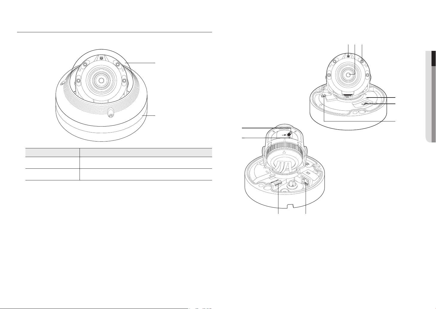
AT A GLANCE (QNO-6070R)
Appearance
Item Description
a
Micro SD card slot
(Internal space of the product) This is a slot in which you can insert a Micro SD card.
b
Reset button
The button restores all camera settings to the factory default.
Press and hold for about 5 seconds to reboot the system.
J
If you reset the camera, the network settings will be adjusted so that DHCP can be
enabled. If there is no DHCP server in the network, you must run the IP Installer
program to change the basic network settings such as IP address, Subnet mask,
Gateway, etc., before you can connect to the network.
c
Sunshield Hold
It fixes the sunshield with the camera.
d
Sunshield
It protects the camera from the direct sunlight.
e
Focus control lever
N Focusing on a near object (Near)
F Focusing on a far object (Far)
Release the lever and move it to left or right to adjust the lens focus.
Turn the lever clockwise to fix the adjusted position to prevent it from being moved.
f
Zoom control lever
T Zoom in (Tele)
W Zoom out (Wide)
Release the lever and move it to left or right to zoom the lens in or out.
Turn the lever clockwise to fix the adjusted position to prevent it from being moved.
b ca
d
e
f
CAUTION:Be ware of the
Rated Voltage and Polarity
of the power connection.
a
b
c
d
English _11
●● OVERVIEW
Components
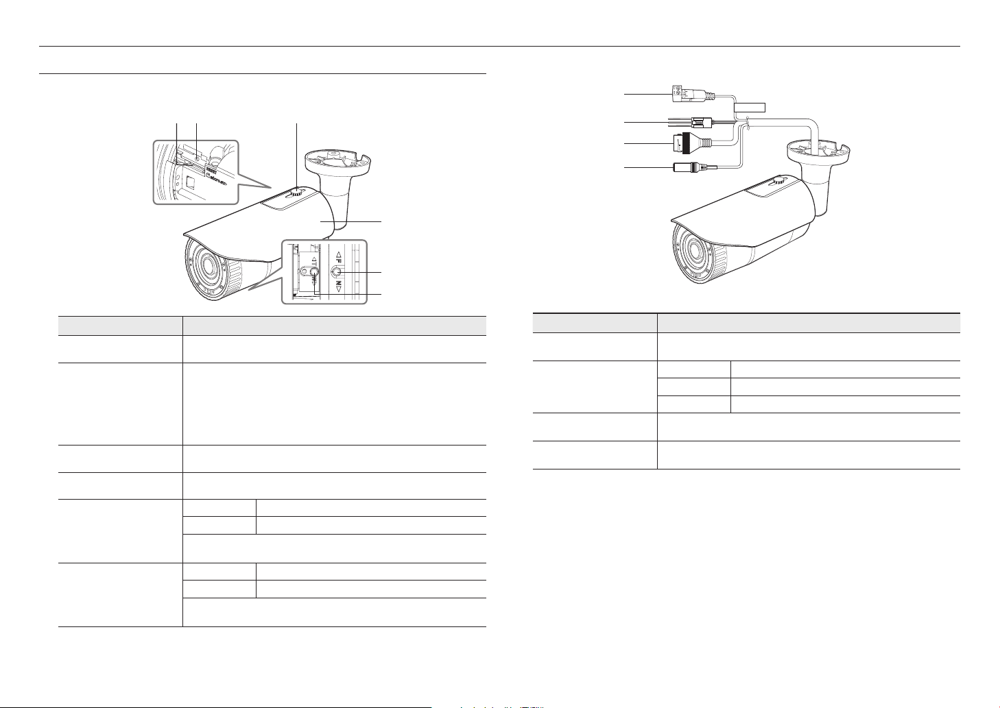
AT A GLANCE (QNV-6070R)
Appearance
Item Description
a
Dome cover
Case cover used to protect the lens and the main unit.
b
Camera Case
Housing part that covers the camera body.
a
b
NETWORK
LINK
ACT
RESET
gh
12345
ALM IN/OUT
AUDIO IN
DC12V
RESET
FRONT
d
f
e
bca
j
i
overview
12_ overview
Item Description
a
Illumination Sensor Detects incoming light to control the IR LED.
b
Lens Lens for the camera.
c
IR LED These infrared LED’s are controlled by the illumination sensor.
d
Reset button
The button restores all camera settings to the factory default.
Press and hold for about 5 seconds to reboot the system.
J
If you reset the camera, the network settings will be adjusted so that DHCP can be
enabled. If there is no DHCP server in the network, you must run the IP Installer
program to change the basic network settings such as IP address, Subnet mask,
Gateway, etc., before you can connect to the network.
e
Audio and alarm cable port
Terminal to which the audio and alarm cable is connected in order to connect with an
external alarm device/microphone.
f
Power Port Port for power terminal block.
g
Network Port Used to connect the PoE or Ethernet cable for network connection.
h
Micro SD Memory Card
Compartment
Compartment for the Micro SD memory card.
i
Zoom control lever
T Zoom in (Tele)
W Zoom out (Wide)
Release the lever and move it to left or right to zoom the lens in or out.
Turn the lever clockwise to fix the adjusted position to prevent it from being moved.
j
Focus control lever
N Focusing on a near object (Near)
F Focusing on a far object (Far)
Release the lever and move it to left or right to adjust the lens focus.
Turn the lever clockwise to fix the adjusted position to prevent it from being moved.
English _13
●● INSTALLATION & CONNECTION
installation & connection
INSTALLATION (QND-6070R)
Precautions before installation
Ensure you read out the following instructions before installing the camera:
• It must be installed on the area (ceiling or wall) that can withstand 5 times the weight of the camera
including the installation bracket.
• Stuck-in or peeled-off cables can cause damage to the product or a fire.
• For safety purposes, keep anyone else away from the installation site.
And put aside personal belongings from the site, just in case.
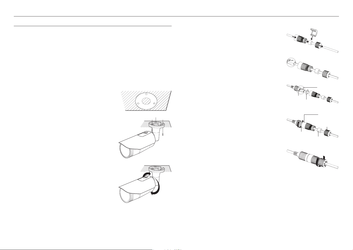
Disassembling
1. Use one hand to hold the camera’s bottom part and turn the cover
counterclockwise with another hand to separate it.
2. Lift up the inner cover to separate it.
Installation
1. Attach the installation template to the selected area and punch 3
holes as shown in the figure.
2. Using 2 tapping screws provided, fix the camera at 2 holes drilled
with a template.
`
Set the < > mark imprinted on the camera to face the direction of camera
monitoring.
3. Connect the camera internal terminal with the corresponding
cable.
4. Adjust the lens in a desired direction by referring to the “Adjusting
the monitoring direction for the camera” section. (page 18)
J
`
We recommend you not to touch the lens as the camera lens has been
properly focused in the final process of manufacturing. If so, the lens may be
out of focus or stained by alien substances.
5. Please connect the inner cover to the main body.
6. While grabbing the bottom side of the camera with your hand, please
grab and push its cover with the other hand to align the two arrow signs,
as shown in the figure.
J
`
To assemble the dome cover, make the arrows match each other and press the
cover firmly.
If the dome cover is rotated during assembly or is assembled incorrectly, diffused
reflection may occur or the lens section may rotate, which will cause the shooting
range to be changed.
`
Make sure that the dome cover is correctly connected to the bottom part as shown
in the figure.
If the snap-fit is not connected correctly, the dome cover may fall, which may cause
injury.
NETWORK
ACT
LiNK
Dome Cover
NETWORK
ACT
LiNK
NETWORK
ACT
LiNK
NETWORK
ACT
LiNK
installation & connection
14_ installation & connection
INSTALLATION (QNO-6070R)
J
`
This camera is waterproof and in compliance with the IP66 spec, but the jack connected to the external cable is not. You are
recommended to install this product below the edge of eaves to prevent the cable from being externally exposed.
Precautions before installation
Ensure you read out the following instructions before installing the camera:
• It must be installed on the area (ceiling or wall) that can withstand 5 times the weight of the camera
including the installation bracket.
• Stuck-in or peeled-off cables can cause damage to the product or a fire.
• For safety purposes, keep anyone else away from the installation site.
And put aside personal belongings from the site, just in case.
Installation
1. Attach the installation template at a desired location and make 3
holes the same size as shown in the picture below.
2. Insert and fasten 3 tapping screws provided into 3 holes to secure
the camera.
3. Connect the appropriate cables with camera terminals.
4. Adjust the camera direction using the L wrench provided.
J
`
When you adjust the camera position using a bracket, please loosen the
bracket screw, adjust the camera, and tighten it. If you attempt to adjust it
forcibly while the screw is tight, it may result in a scratch or other problems.
How to connect the RJ45 waterproof cable to a LAN cable
1. Insert it through the arrow direction.
2. Connect the LAN connector (male) to the cable.
3. Connect the RJ45 modular jack (female) to the RJ45 connector
(male).
J
`
Please, keep each of the parts separated.
4. Assemble by rotating the RJ45 modular jack (female) and the RJ45
protection cover clockwise (Follow the arrow).
5. Assemble by rotating RJ45 protection cover and back cover
clockwise (Follow the arrow).
When the back cover is assembled, the cable waterproof gasket is
tightly attached to the cable to make it waterproof.
J
`
You must fully assemble it to rotate the back cover up to the end of the screw
thread of the RJ45 connector.
Mounting Template
Cable Line
RJ45 connector
(male)
RJ45 modular
jack (female)
Rubber ring
RJ45 connector
protection cover
Back cover
Cable waterproof
gasket
Rubber ring
English _15
●● INSTALLATION & CONNECTION
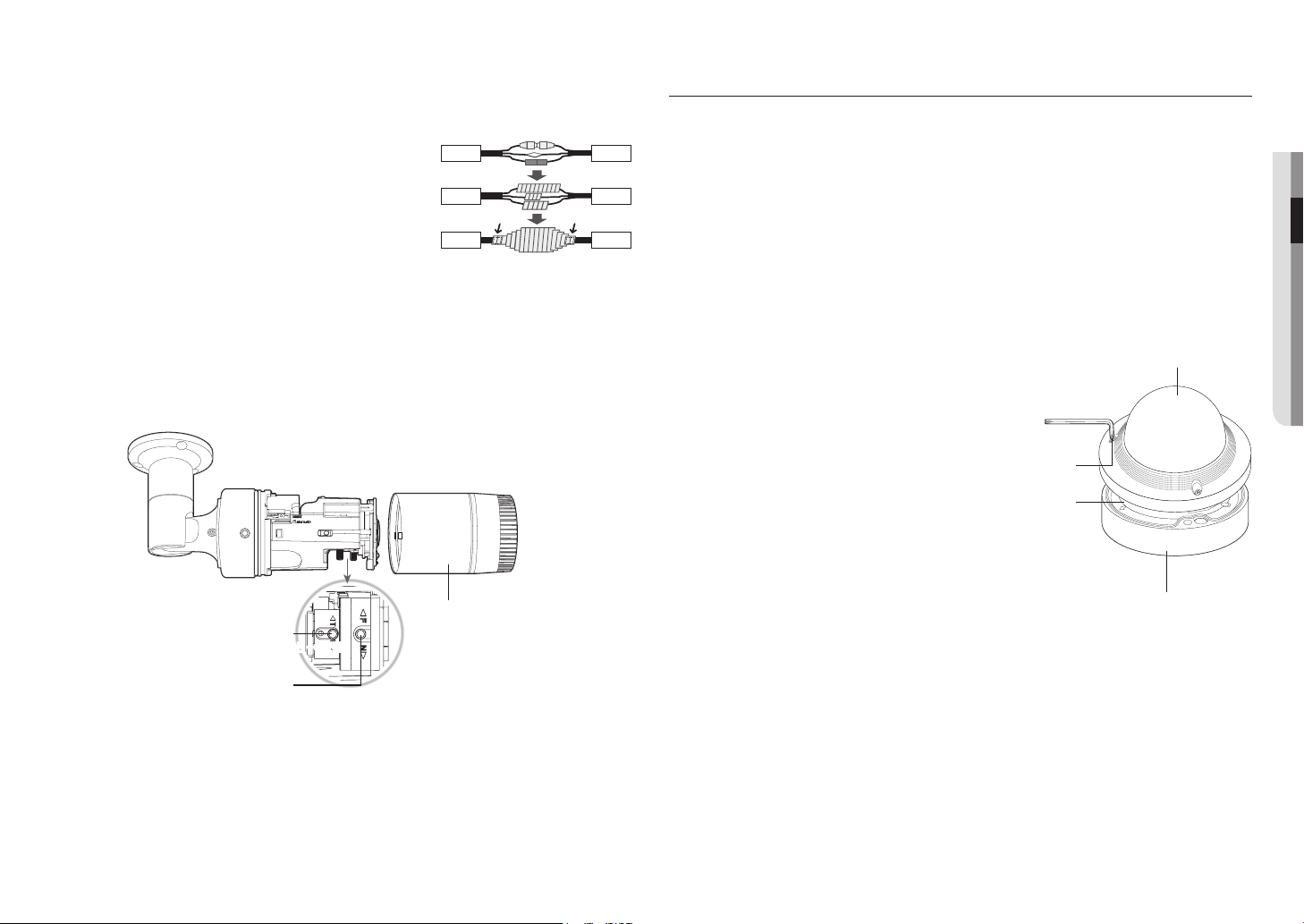
Outdoor installation
When you install it outside of the building, please waterproof it with waterproof butyl rubber tape (can be
purchased in stores) so that water does not leak from the gap of the cable connected to the outside.
1. Connect the power, I/O, AUDIO, and LAN cables.
2. Wrap the black cable jacket (Area A) and the cable connection
area with waterproof (butyl rubber) tape so that more than half of
the butyl rubber tape is overlapped.
J
`
If the cable jacket is not waterproofed properly, then it can directly cause
leakage. Make sure to protect the cable with a dense layer of taping.
`
Waterproof butyl tape is made of butyl rubber that can be stretched to twice its normal length.
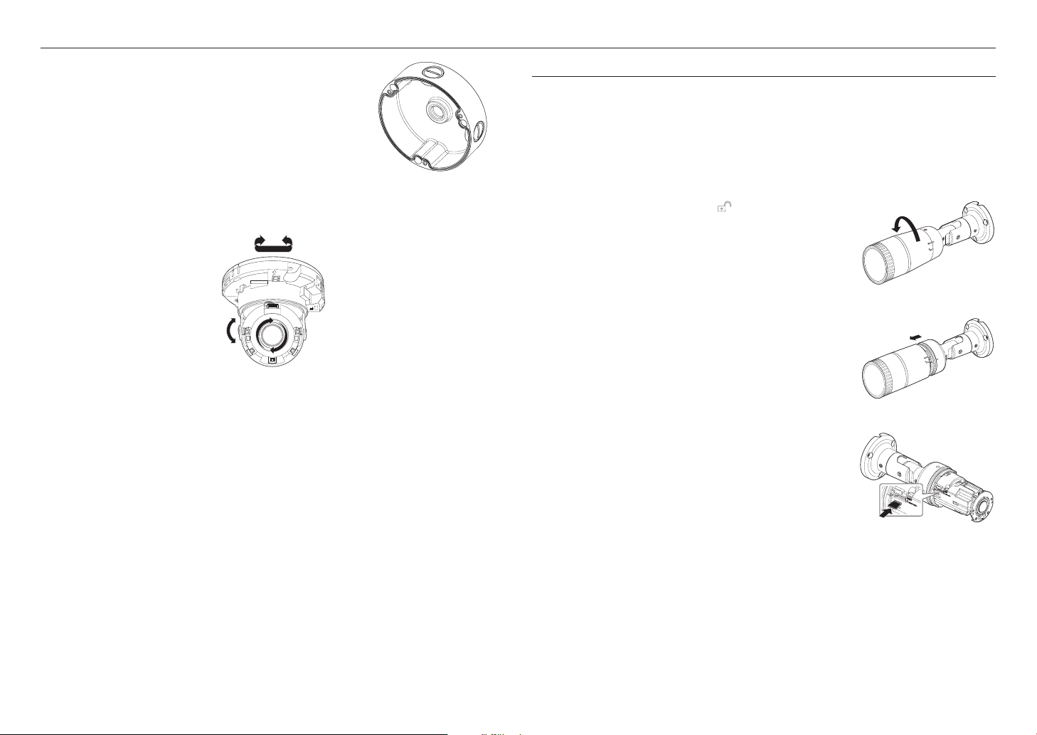
To adjust the zoom factor or focus
1. Loosen the front cover as shown.
2. Loosen the zoom/focus lever slightly.
3. Position the zoom/focus lever to WIDE (NEAR) or TELE (FAR) as appropriate.
4. Then, tighten the zoom/focus lever to fix the adjusted position.
5. Turn the front cover to tighten it.
J
`
To ensure seamless waterproofing, tighten up the front cover by turning it to the end.
When combining the front cover, please combine the main body and the front cover so that the LOCK indicator is interlocked.
`
Use the lever to adjust the zoom factor or focus, and turn the lever clockwise to fix it.
`
Before you can adjust the zoom factor/focus of the lens, loosen and remove the front cover.
Camera
Camera
Camera
System
System
System
AA
Front cover
Zoom Lever
Focus Lever
WIDE
↔
TELE
FAR
↔
NEAR
INSTALLATION (QNV-6070R)
J
`
This camera is waterproof and in compliance with the IP66 spec, but the jack connected to the external cable is not. You are
recommended to install this product below the edge of eaves to prevent the cable from being externally exposed.
Precautions before installation
Ensure you read out the following instructions before installing the camera:
• It must be installed on the area (ceiling or wall) that can withstand 5 times the weight of the camera
including the installation bracket.
• Stuck-in or peeled-off cables can cause damage to the product or a fire.
• For safety purposes, keep anyone else away from the installation site.
And put aside personal belongings from the site, just in case.
Disassembling
1. Using the L wrench provided, turn the 3 fastening bolts
on the dome cover counter clockwise to remove the
cover.
12345
ALM IN/OUT
AUDIO IN
DC12V
RESET
FRONT
Dome cover
Camera Case
Bolts
Camera Body
installation & connection
16_ installation & connection
Installation
1. Using the template provided as an accessory, drill holes for
installation screws (at least 55mm deep with a diameter of 6mm).
2. Align the installation holes of the camera, and then insert and
fasten tapping screws (M4.5 x L50).
3. Connect and arrange the necessary cables lest that they should
be damaged or twisted while installing the camera.
4. Adjust the lens in a desired direction by referring to the “Adjusting
the monitoring direction for the camera” section. (page 18)
5. Close the dome cover.
`
Securely fasten the fastening bolt using an L wrench to prevent water from
leaking.
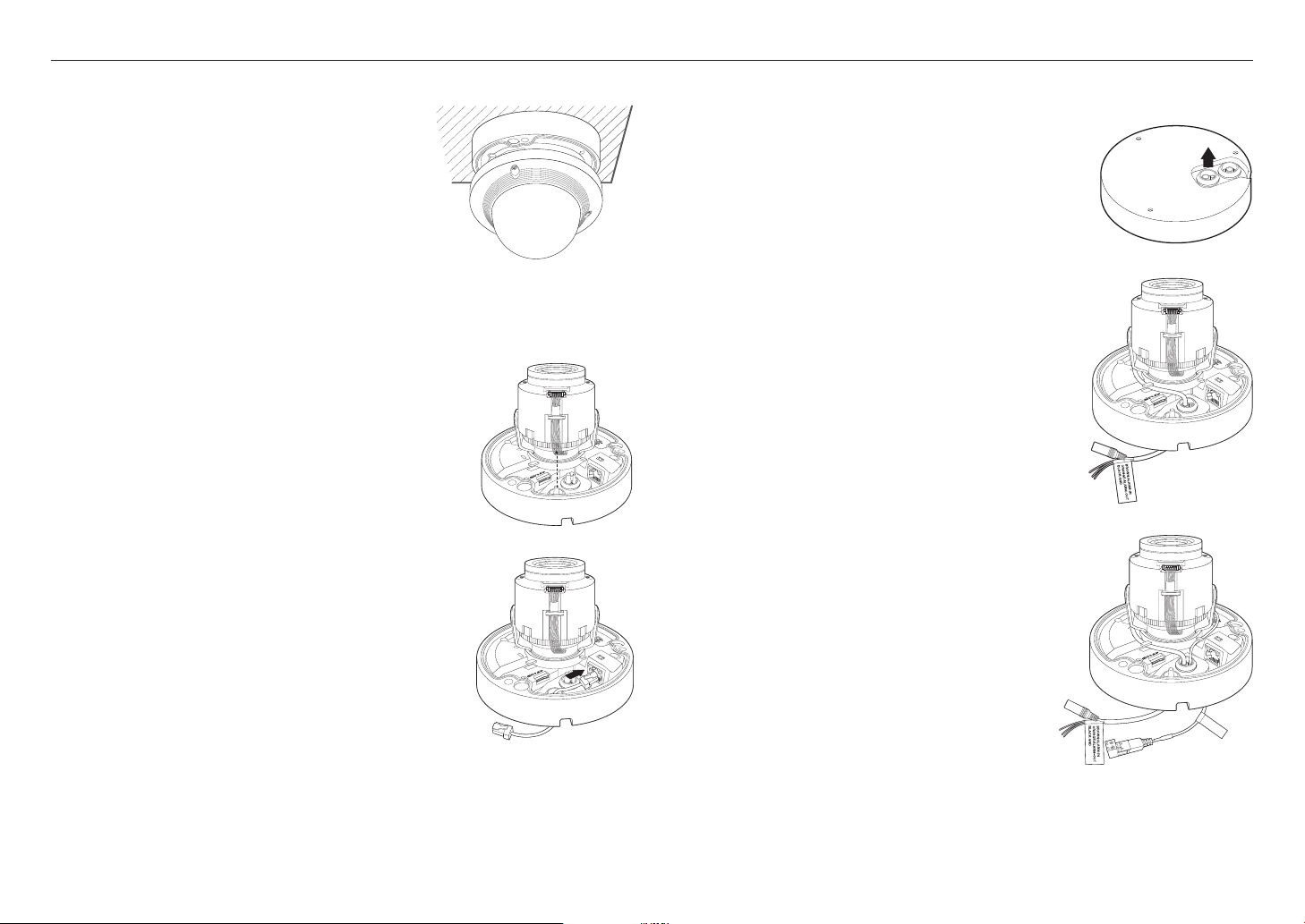
Connecting the LAN cable
1. Remove the dome cover and the case.
2. Pull out the long projected part of the rubber plug on the bottom and
remove it as shown in the figure.
J
`
Use an appropriate cable bush for the LAN cable to be connected.
- Basic camera : Use the cable with a diameter of Ø5~6.5.
- Components provided : Use the cable with a diameter of Ø7~8.5.
3. Insert the LAN cable into the large hole made by removing the projected
part of the rubber plug in step 2 above.
4. Remove the sheath with a cable cutter, and align the cables.
5. Connect the LAN cable with a LAN connector, and insert it into the LAN
tool.
6. Connect the finished cable to the Ethernet port.
12345
ALM IN/OUT
AUDIO IN
DC12V
RESET
FRONT
Connecting the audio/alarm cable and power cable
1. Remove the dome cover and the case.
2. Pull out the rubber plug on the bottom as shown in the figure.
3. Insert the alarm/audio cable through the hole created by removing the
rubber cap in No. 2, and connect the cable to the alarm terminal.
4. When installing the camera, arrange the cables by hanging them up on
the fixing hook to prevent the cables from being damaged or caught.
5. Put the rubber cap located on the alarm/audio cable in the hole.
6. Insert the power cable through the small hole and hang the cable
up on the fixing hook.
7. Connect the power cable to the power terminal block.
8. Adjust the lens in a desired direction by referring to the “Adjusting
the monitoring direction for the camera” section.
(page
18
)
9. Attach the dome cover.
NETWORK
LINK
ACT
RESET
NETWORK
LINK
ACT
RESET
NETWORK
LINK
ACT
RESET
CAUTION: Be w are of the
Rated Voltage and Po larit y
of the power connec tion.
NETWORK
LINK
ACT
RESET
English _17
●● INSTALLATION & CONNECTION
Attaching to the unbundled adapter
Choose and purchase a necessary one of the following options (unbundled) that is suitable to the installation
site or for your convenience.
1. Remove the dome cover from the case by referring to the “Disassembling” section. (page
16
)
2. Use the provided machine screw to fix the camera case to the unbundled adapter.
3. Connect and arrange the necessary cables lest that they should be damaged or twisted while installing the
camera.
4. Install the camera body in the reverse order of “Disassembling”.
5. Adjust the lens in a desired direction by referring to the “Adjusting the monitoring direction for the
camera” section. (page 18)
6. Close the dome cover.
`
Securely fasten the fastening bolt using an L wrench to prevent water from leaking.
Outdoor installation
When you install it outside of the building, please waterproof it with waterproof butyl rubber tape (can be
purchased in stores) so that water does not leak from the gap of the cable connected to the outside.
1. Connect the power, I/O, BNC, and LAN cables.
2. Wrap the black cable jacket (Area A) and the cable connection area
with waterproof (butyl rubber) tape so that more than half of the
butyl rubber tape is overlapped.
J
`
If the cable jacket is not waterproofed properly, then it can directly cause
leakage. Make sure to protect the cable with a dense layer of taping.
`
Waterproof butyl tape is made of butyl rubber that can be stretched to twice
its normal length.
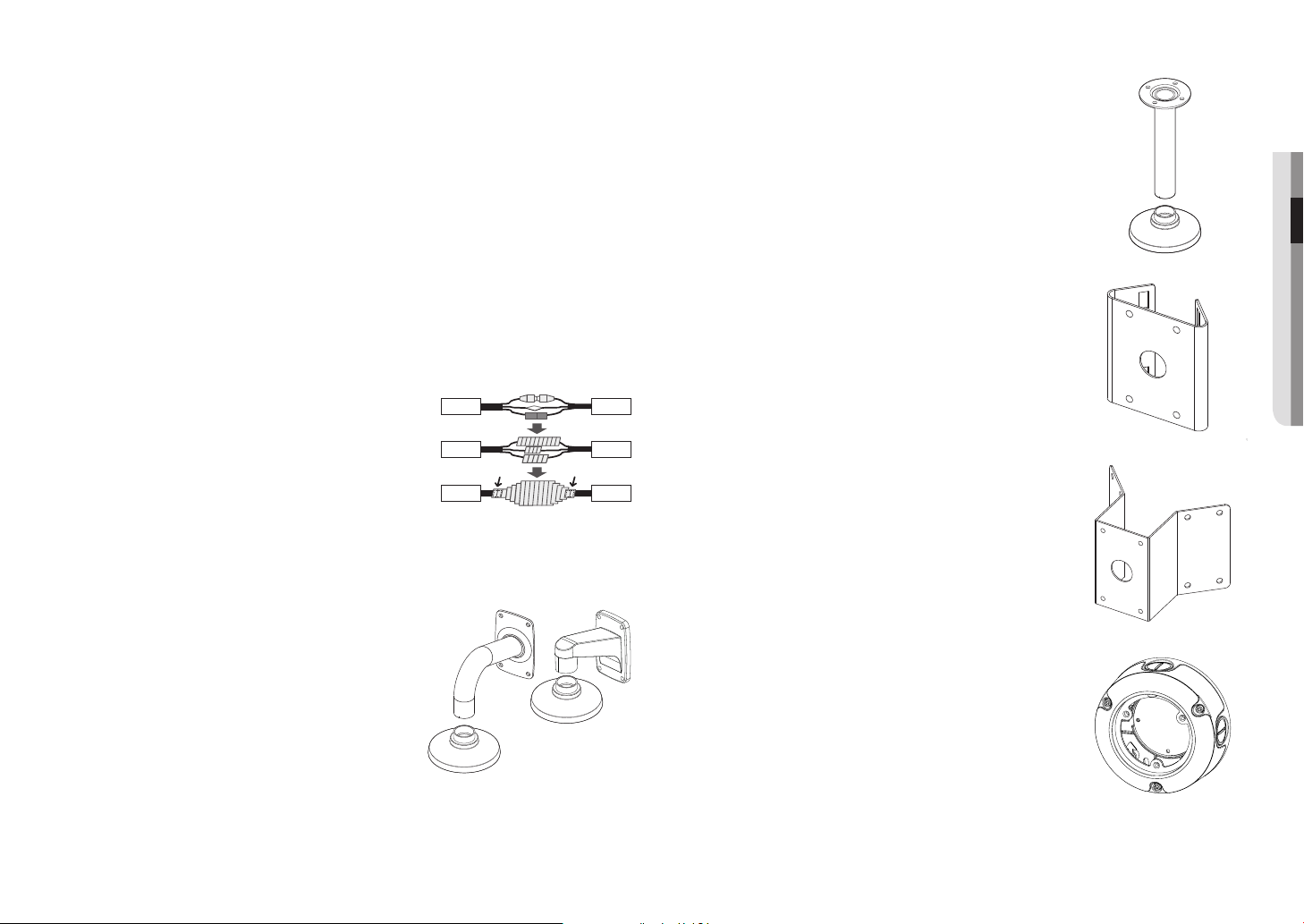
Optional Accessories for Installation
For your easier installation, you can purchase appropriate optional accessories available.
1. WALL MOUNT ADAPTOR(SBP-300WM or SBP-300WM1)/
HANGING MOUNT(QND-6070R : SBP-122HM, QNV-6070R :
SBP-301HM2)
This adaptor is used when installing the dome camera onto a
wall.
Camera
Camera
Camera
System
System
System
AA
2. CEILING MOUNT ADAPTOR(SBP-300CM)/HANGING MOUNT(QND-
6070R : SBP-122HM, QNV-6070R : SBP-301HM2)
This adaptor is used when installing the dome camera on a concrete
ceiling.
3. POLE MOUNT ADAPTOR(SBP-300PM)
This is an adaptor for WALL MOUNT ADAPTOR (SBP-300WM or SBP-
300WM1) installation on a pole whose diameter is bigger than 80mm.
4. CORNER MOUNT ADAPTOR (SBP-300KM)
This is an adaptor for WALL MOUNT ADAPTOR (SBP-300WM or
SBP-300WM1) installation on the corner of wall joint.
5. BULLET BACK BOX (SBO-100B1)
Adapter used for the installation of a bullet camera on the wall or
ceiling.
installation & connection
18_ installation & connection
6. VANDAL BACK BOX (SBV-136B)
Adapter used for the installation of a vandal camera on the wall or
ceiling.
Adjusting the monitoring direction for the camera (QND-6070R/QNV-6070R)
`
Adjusting the monitoring direction
You can adjust the camera direction only when the camera is fixed on the ceiling.
Where, rotating the camera unit to the left or right is called Pan, adjusting the tilt is called Tilt, and turning the
lens on its axis is called Rotation.
- The effective range of pan is a total of 350 degrees.
- The effective range of rotation is a total of 355 degrees.
- The effective range of tilt is a total of 67 degrees.
J
`
The image can be covered up by the camera case depending on the angle.
`
Do not forcefully turn the focus/zoom lens after the dome case is disassembled.
Otherwise, it may cause an incorrect focus due to a motor failure.
`
Methods of adjustment
1. After installing the camera, adjust the panning angle in consideration of the monitoring direction.
2. Set the horizontal angle so that the image is not reversed.
3. Adjust the tilt angle so that the camera faces toward the monitoring object.
INSERTING/REMOVING A MICRO SD MEMORY CARD
J
`
Disconnect the power cable from the camera before inserting the Micro SD memory card.
`
Do not insert the Micro SD memory card while it’s upside down by force.
Otherwise, it may damage the Micro SD memory card.
`
When it rains or the humidity is high, insertion or ejection of a Micro SD card is not recommended.
`
Disassembly of the product cover should be finished within 5 minutes, or there will be the risk of internal dew condensation.
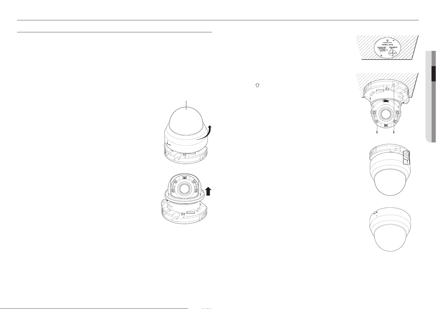
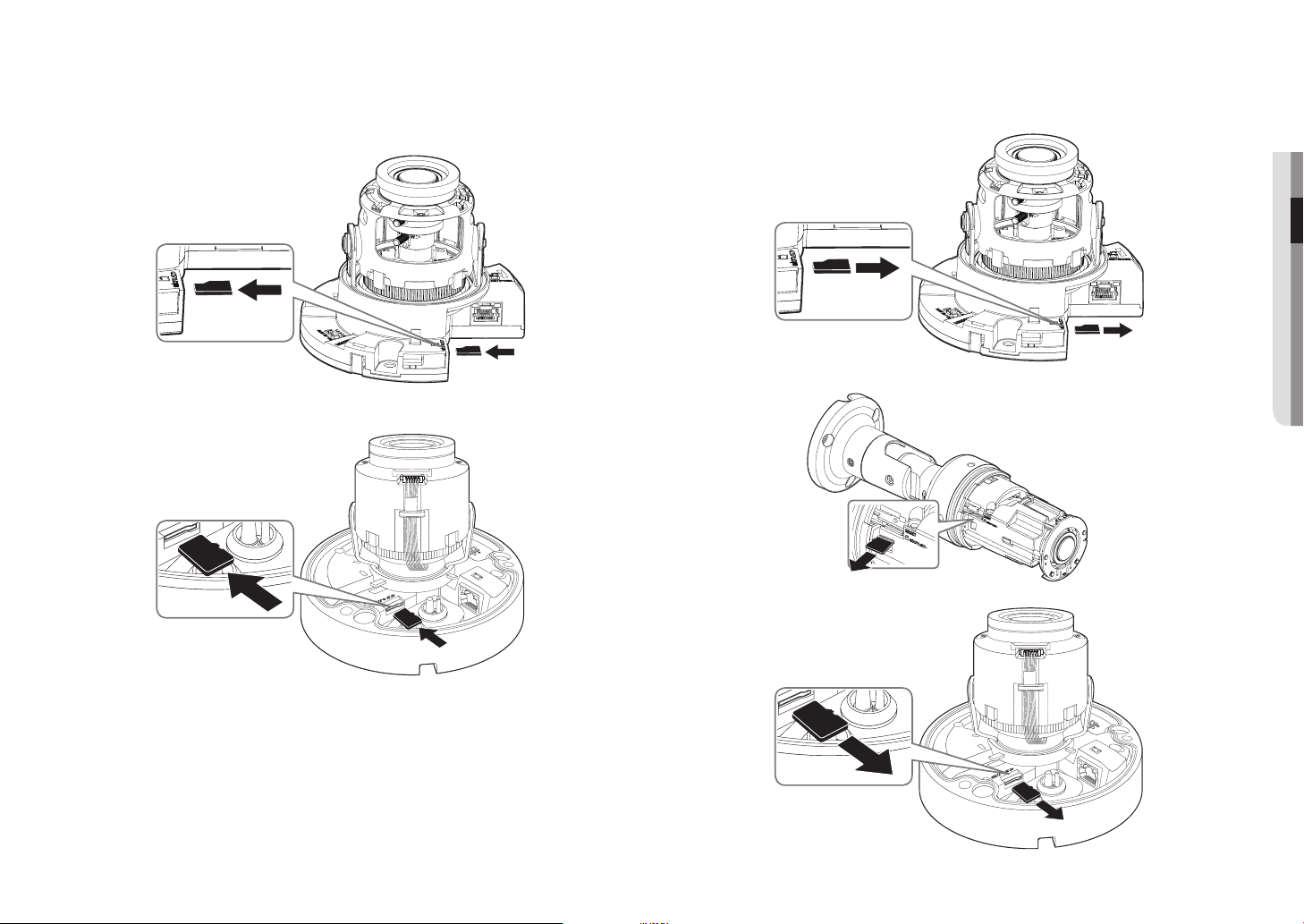
Inserting a Micro SD Memory Card (QNO-6070R)
1. Turn the front cover to the UNLOCK [ ] direction.
2. Pull and separate the front cover.
3. Insert a Micro SD card in the arrow direction shown in the figure.
NETWORK
ACT
LiNK
Pan
Tilt
Lens rotation
English _19
●● INSTALLATION & CONNECTION
Inserting a Micro SD Memory Card (QND-6070R/QNV-6070R)
1. Separate the Dome cover of the camera.
2. Insert a Micro SD card in the arrow direction shown in the figure.
<QND-6070R>
Removing a Micro SD Memory Card
Gently press down on the exposed end of the memory card as shown in the diagram to eject the memory
card from the slot.
<QND-6070R>
<QNO-6070R>
NETWORK
LINK
ACT
RESET
NETWORK
LINK
ACT
<QNV-6070R>
NETWORK
LINK
ACT
RESET
NETWORK
LINK
ACT
<QNV-6070R>
installation & connection
20_ installation & connection
Micro SD/SDHC/SDXC
Contacts
J
`
Pressing too hard on the Micro SD memory card can cause the card to shoot out uncontrollably from the slot when released.
`
Before removing your Micro SD memory card, turn off the camera or go to <Storage>, turn the device off, and press the [Apply
(
)] button. (Page 53)
`
If you turn off the camera or remove the Micro SD memory card that contains data from the product, the data may be lost or
damaged.
MEMORY CARD INFORMATION (NOT INCLUDED)
What is a memory card?
The memory card is an external data storage device that has been developed to offer an entirely new way to
record and share video, audio, and text data using digital devices.
Selecting a memory card that’s suitable for you
Your camera supports Micro SD/SDHC/SDXC memory cards.
You may, however, experience compatibility issues depending on the model and make of the memory card.
For your camera, we recommend you use a memory card from the following manufacturers:
Micro SD/SDHC/SDXC Memory Card : Sandisk, Transcend
It is recommended to use a 4 to 128GB (uhs-1 class) memory card for this camera.
Playback performance can be affected depending on the speed of memory card, so use the high-speed
memory card.
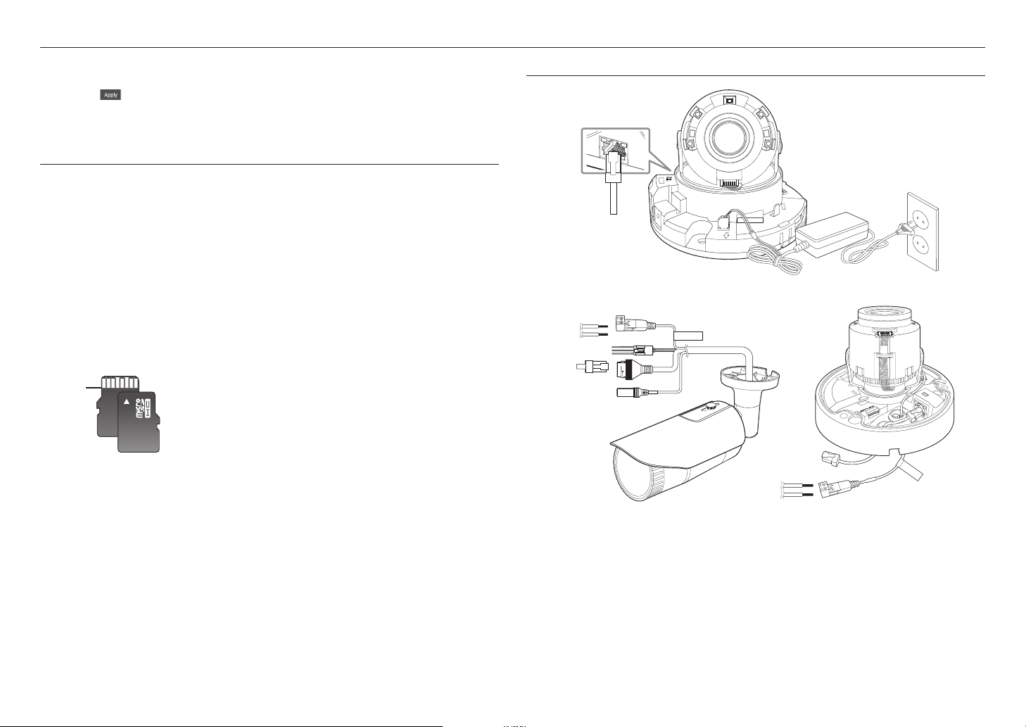
Memory Card Components
CONNECTING WITH OTHER DEVICE
CAUTION:Be ware of the
Rated Voltage and Polarity
of the power connection.
<QNO-6070R>
Ethernet
Power
NETWORK
ACT
LiNK
<QND-6070R>
Power
Ethernet
<QNV-6070R>
CAUTION: Be ware o f the
Rated Voltage and P olari ty
of the power conne ction .
NETWORK
LINK
ACT
RESET
Ethernet
Power
English _21
●● INSTALLATION & CONNECTION
Ethernet Connection
Connect the Ethernet cable to the local network or to the Internet.
Power Supply
Use the screwdriver to connect each line (+, –) of the power cable to the corresponding power port of the
camera.
J
`
If both PoE and DC 12V are applied simultaneously, the product will be supplied with power from PoE.
- You can also use a router featuring PoE to supply power to the camera.
- Use PoE that is compliant with the IEEE 802.3af protocols.
- It is advisable to use only one power source from PoE and DC 12V.
`
Be careful not to reverse the polarity when you connect the power cable.
`
If you want to connect an external device, you must turn off the external device before proceeding.
Power Cable Specification for Each Model
In case of DC 12V Input:
Wire Type (AWG) #22 #20 #18
Cable Length (Max.) 24m 38m 60m
Network Cable Specification
Item Contents Remark
Connector RJ45
Ethernet 10/100BASE-T 10/100 Mbps
Cable UTP Category 5e
Max Distance 100M DC Resistance
≤
0.188 Ω/m
PoE Support IEEE 802.3af
J
`
If you use a cable other than Category 5e standards, 100m of transmission distance is not guaranteed.
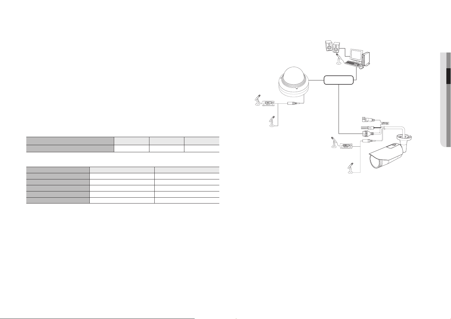
Connecting to Audio Input
1. Connect the AUDIO IN port of the camera with the microphone or LINE OUT port of the amplifier that the
microphone is connected to.
M
`
You can use the built-in microphone in the camera without connecting an external microphone.
(only available in QND-6070R)
2. Check the specifications for audio input.
• Audio Codec
- Audio In : G.711 PCM (Bit Rate: 64kbps / Sampling Frequency: 8kHz), G.726 ADPCM (Bit Rate:
16Kbps, 24Kbps, 32Kbps, 40Kbps / Sampling Frequency: 8kHz)
• Full duplex Audio
• Audio in (QND-6070R) : Selectable (Built-in microphone), Supported voltage: 2.5VDC (4mA), Input
impedance: 2K Ohm
• Audio in (QND-6070R/QNV-6070R) : Selectable (microphone/Line-in), Supported voltage: 2.5VDC (4mA),
Input impedance: 2K Ohm
Network
Speaker
Microphone
Microphone
Microphone
Microphone
Microphone
Amp
Amp
PC

installation & connection
22_ installation & connection
Connecting to the I/O port box
Connect the Alarm I/O cable to the corresponding port of the port box.
<QNO-6070R>
CAUTION:Be ware of the
Rated Voltage and Polarity
of the power connection.
SensorAlarm
(Warning lamp)
• ALARM-IN : Used to connect the alarm input sensor or external day/night sensor.
• ALARM-OUT : Used to connect the alarm output signal.
• GND : Common port for alarm in/output signal.
J
`
If devices (e.g., flashing light and siren) that exceed the voltage and current specifications are connected by using the open
collector method, it may cause malfunction.
Refer to the “Alarm Out Wiring Diagram” when connecting devices that exceed the voltage and current specifications. (page
23)
To connect the external sensor
Connect one strand of each signal line (2-strand) of the sensors to the [ALARM IN] port, and connect the
other strand to the [GND] port.
<QNV-6070R>
12345
ALM IN/OUT
AUDIO IN
DC12V
RESET
FRONT
Sensor Alarm
(Warning lamp)
<QND-6070R>
Sensor Alarm
(Warning lamp)
English _23
●● INSTALLATION & CONNECTION
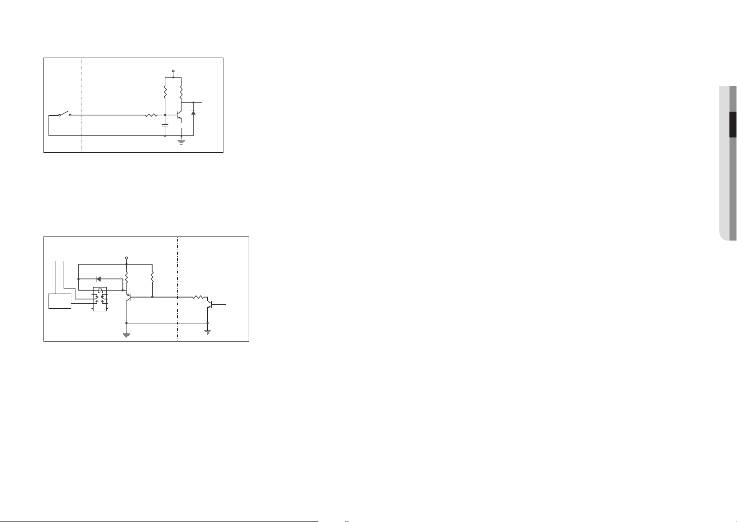
Alarm In Wiring Diagram
To connect the alarm out
If devices (e.g., flashing light and siren) that exceed the voltage and current specifications are connected by
using the open collector method, it may cause malfunction.
Refer to the alarm out connection diagram below when connecting devices that exceed the voltage and
current specifications.
Alarm Out Wiring Diagram
Sensor
GND
RESISTORALARM IN (5mA SINK)
RESISTOR RESISTOR
VCC_3.3V
DIODE
GND
MLCC
TRANSISTOR
External
connection
Inside of the camera
Warning lamp /
Siren power
Warning lamp /
Siren
(
-
) (
+
)
ALARM OUT (12VDC 20mA MAX)
RESISTOR 10K ohm
DIODE
RELAY
DC 5V or 3.3V
TRANSISTOR
GND
GND
TRANSISTOR
External connection Inside of the camera
GND
RESISTOR
 Loading...