


Samsung DV316BGC, DV316BGW, DV3C6BGW, DV316LGS, DV326LGS Service Manual
...CLOTHES DRYER
Model code :
SERVICE
DV316LGW/XAA
DV306LEW/XAA
DV316LEW/XAA
DV326LES/XAA
DV3C6BEW/XAA
DV316BEW/XAA
DV316BEC/XAA
DV306LGW/XAA
DV316LGW/XAA
DV316LGS/XAA
DV326LGS/XAA
DV3C6BGW/XAA
DV316BGW/XAA
DV316BGC/XAA
Manual
CLOTHES DRYER |
|
THE FEATURE OF PRODUCT |
1. Super Size Capacity
2. Energy Saving
3. Time Saving
CONTENTS
1. PRECAUTIONS |
|
1-1. CAUTION FOR SAFETY DURING SERVICING............................................................................... |
1-1 |
1-2. IMPORTANT SAFETY INFORMATION............................................................................................. |
1-2 |
1-3. PRECAUTIONS UPON INSTALLATION........................................................................................... |
1-6 |
2. PRODUCT SPECIFICATIONS |
|
2-1. THE FEATURE OF PRODUCT......................................................................................................... |
2-1 |
2-2. SPECIFICATIONS OF PRODUCT.................................................................................................... |
2-2 |
2-3. OVERVIEW OF THE DRYER............................................................................................................ |
2-3 |
2-4. THE COMPARATIVE SPECIFICATIONS OF PRODUCT.................................................................. |
2-4 |
2-5. OPTION SPECIFICATIONS.............................................................................................................. |
2-5 |
3. OPERATING INSTRUCTIONS AND INTALLATION |
|
3-1. OVERVIEW OF THE CONTROL PANEL........................................................................................... |
3-1 |
3-2. CYCLE CHART.................................................................................................................................. |
3-3 |
3-3. MAIN FUNCTIONS............................................................................................................................ |
3-4 |
3-4. DESIGNATION OF MAIN COMPONENTS........................................................................................ |
3-6 |
4. ALIGNMENT AND ADJUSTMENTS |
|
4-1. ERROR ITEMS AND DIAGNOSTIC CODES.................................................................................... |
4-1 |
4-2. TEST MODE...................................................................................................................................... |
4-2 |
5. DISASSEMBLY AND REASSEMBLY |
|
5-1. TOOLS FOR DISASSEMBLY AND REASSEMBLY........................................................................... |
5-1 |
5-2. DISASSEMBLY.................................................................................................................................. |
5-2 |
5-3. REASSEMBLY................................................................................................................................... |
5-6 |
6. TROUBLE SHOOTING |
|
6-1. TROUBLE DIAGNOSIS..................................................................................................................... |
6-1 |
6-2. PROBLEM CHECKING AND METHOD OF PCB.............................................................................. |
6-3 |
7. EXPLODED VIEWS AND PARTS LIST |
|
7-1. EXPLODED VIEW OF FRAME, PANEL-CONTROL......................................................................... |
7-1 |
7-2. EXPLODED VIEW OF FRONT.......................................................................................................... |
7-3 |
7-3. EXPLODED VIEW OF DRUM........................................................................................................... |
7-4 |
7-4. EXPLODED VIEW OF DUCT, HEATER, MOTOR............................................................................. |
7-5 |
7-5. BOLT & SCREW PARTS LIST........................................................................................................... |
7-6 |
CONTENTS |
|
8. ELECTRICAL PARTS LIST...................................................................................................................... |
8-1 |
9. BLOCK DIAGRAM................................................................................................................................... |
9-1 |
10. WIRING DIAGRAM.............................................................................................................................. |
10-1 |
11. PCB DIAGRAM.................................................................................................................................... |
11-1 |
12. SCHEMATIC-DIAGRAMS .................................................................................................................. |
12-1 |
13. CIRCUIT DESCRIPTIONS................................................................................................................... |
13-1 |
14. REFERENCE INFORMATION |
|
14-1. MODEL NAME............................................................................................................................... |
14-1 |
14-2. TERMINOLOGY............................................................................................................................ |
14-2 |
14-3. CHECK THESE POINTS IF YOUR DRYER.................................................................................. |
14-4 |
14-4. INFORMATION CODES................................................................................................................ |
14-5 |
14-5. FABRIC CARE CHART.................................................................................................................. |
14-6 |

41#SUHFDXWLRQV
4041#FDXWLRQ#IRU#VDIHW\#GXULQJ#VHUYLFLQJ
1. Do not allow the customer to repair the product.
The person may be injured or the product life may be shortened..
2.Execute A/S after unplugging the power supply unit. Be careful of the electric shocks.
3.Do not plug several plugs in the same outlet.
It may cause a fire due to overheat.
4. Check for damage, pressing or burning of the power plug or outlet.
Replace it promptly if it has a problem.(It may cause the electric shocks or fire)
5. Do not clean the main body with water.
It may cause electric shocks and fire and shorten the product life)
6.The wiring of the harness shall be free from moisture and tightened during serving. It shall not be deviated by certain impact.
7.Remove any dust or filth on the housing section,wiring section,connection section during servicing. Protect from possible cause of fire such as the tracking,shortage etc.
8.Check for any marks of moisture on the electrical parts, harness section etc.
Replace the parts or remove the moisture..
9.Check the assembly status of the parts after servicing. Maintain the status before servicing..
10.Pull out the power cord by holding the plug.
Be careful of electric shocks and when the cord is damaged.
11.Unplug the power plug from the outlet when the dryer is not used. Be careful of electric shocks and fire due to the strike of lightning.
12.Do not use or store sprays or flammable materials(including gasoline,alcohol etc.) around the dryer.
Be careful of explosions or fire due to electric sparks.
13.Do not put bowls of water or wet laundry on the dryer.
If water has penetrated into the dryer, this may cause electric shocks or fire.
14. Do not install the dryer where it will be exposed to bad weather. It may cause electric shocks and fire and shorten the product life.
1-1

15.Do not push the control buttons with an awl,pin, or sharp materials. It may cause electric shocks and damage.
16.Check the wash machine is leveled horizontally and installed properly on the floor. The vibration may shorten the product life..
4051#LPSRUWDQW#VDIHW\#LQIRUPDWLRQ
To avoid risk of fire, electric shock, serious injury, or death when using your dryer, follow these basic precautions:
1.Read all instructions before using dryer.
2.Install dryer according to Installation Instructions. Refer to the Grounding Instructions in the Installation Instructions for proper grounding of the dryer.
3.Do not dry articles that have been cleaned in, washed in, soaked in, or spotted with gasoline, drycleaning solvents, or other flammable or explosive substances. Vapors could ignite or explode.
4.Do not use dryer to dry clothes which have traces of any flammable substance, such as vegetable oil, cooking oil, machine oil, flammable chemicals, thinner, etc., or anything containing wax or chemicals, such as mops and cleaning cloths. Flammable substances may cause fabric to catch fire by itself.
5.Do not store or use gasoline or other flammable vapors and liquids near this or any other appliance.
6.Do not allow children to play on or in dryer. Close supervision of children is necessary when dryer is used near children, a safety rule for all appliances.
7.Before dryer is removed from service or discarded, remove doors to drying compartment.
8.Do not reach into dryer if cylinder is revolving.
9.Do not install or store dryer where it will be exposed to water and/or weather.
10.Do not tamper with dryer controls.
11.Do not repair or replace any part of dryer or attempt any service, unless specifically recommended in user-maintenance instructions or in published user-repair instructions that you understand and have skills to carry out, if you are a consumer.
12.To reduce risk of electric shock or fire, do not use extension cords or adapters to connect dryer to electrical power source.
13.Use the dryer only for its intended purpose, drying clothes.
14.Always disconnect dryer from electrical supply before attempting any service. Disconnect power cord by grasping the plug, not the cord.
15.Do not use heat to dry articles containing foam rubber or similarly textured rubberlike materials.
1-2

16.Always clean the lint filter after every load. A layer of lint in the filter reduces drying efficiency and pro longs drying time.
17.Use only fabric softeners or products to eliminate static that are appropriate for automatic dryers.
18.Keep your dryer in good condition. Bumping or dropping dryer can damage safety features. If damage occurs, have dryer checked by qualified service technician.
19.Replace worn power cords and/or loose plugs.
20.Do not tumble fiberglass curtains and draperies unless the label says it can be done. If they are dried, wipe out the cylinder with a damp cloth to remove particles of fiberglass.
21.Always read and follow manufacturer s instructions on packages of laundry aids. Heed all warnings or precautions. To reduce risk of poisoning or chemical burns, keep products away from children at all times, preferably, in a locked cabinet.
22.Never operate dryer with guards and/or panels removed.
23.Do not operate dryer with missing or broken parts.
24.Do not bypass safety devices.
25.Keep area around the exhaust opening and adjacent surrounding areas free from accumulation of
lint, dust, and dirt.
26.Interior of dryer and exhaust duct should be cleaned periodically by qualified service personnel.
27.Dryer will not operate with loading door open. DO NOT bypass door safety switch by permitting dryer to operate with door open. Dryer will stop tumbling when door is opened. Do not use dryer if it does not stop tumbling when door is opened or starts tumbling without pressing or turning the START mechanism. Remove the dryer from use and call the service person.
28.Remove laundry immediately after the dryer stops.
29.ALWAYS follow the fabric care instructions supplied by the garment manufacturer.
1-3

Hohfwulfdo#Vhuylfh#Lqirupdwlrq
Electrical Dryers
- 240 VAC, 60 Hz, 30 Amps, 3-wire or 4-wire installations Gas Dryers
- 120 VAC, 60 Hz, 15 Amps, 3 wire installations
About Ground Wires
In the event of an electrical short circuit, a
ZDUQLQJ
To reduce the risk of fire, electric shock, serious injury or death, all wiring and grounding must conform with the latest edition of the National Electric Code, or the Canadian Electrical Code, and such local regulations as might apply. It is the customer s responsibility to have the wiring and fuses checked by a qualified electrician to make sure your home has adequate electrical power to operate the dryer.
ZDUQLQJ
To avoid risk of personal injury or death due to electrical shock:
-Observe all local codes and ordinances.
-Disconnect electrical power to unit before servicing.
-Ground appliance properly.
-Check with a qualified electrician if you are not sure this appliance is properly grounded.
-DO NOT ground to gas line.
-DO NOT ground to cold water pipe if pipe is interrupted by plastic, nonmetallic gas kets, or other insulating (nonconducting) materials.
-DO NOT modify plug on power cord.
If plug does not fit electrical outlet, have proper outlet installed by qualified elec trician.
-DO NOT have a fuse in the neutral or ground circuit. A fuse in the neutral or ground circuit could result in an electrical shock.
-DO NOT use an extension cord with this appliance.
-DO NOT use an adapter plug with this appliance.
-DO NOT pinch powe cord.
ZDUQLQJ
To reduce the risk of fire and exposure to combustion gases, the dryer MUST be exhausted to the outdoors.
DO NOT exhaust dryer air into a window well, gas vent, chimney or enclosed, unventilated area, such as an attic, wall, ceiling, crawl space under a building or concealed space of a building.
1-4

Jdv#Gu|hu#Srzhu#Vxsso|
This equipment MUST be grounded. In the event of an electrical short circuit, grounding reduces the risk of electric shock by providing an escape wire for the electrical current. This unit is equipped with a cord having a grounding wire with a grounding plug. The plug must be plugged into an outlet that is properly installed and grounded.
Consult a qualified electrician or servicer if grounding instructions are not completely understood, or if doubt exists as to whether the equipment is properly grounded.
Do not use an extension cord. If the product power cord is too short, have a qualified electrician install a three slot receptacle.
This unit should be plugged into a separate 60 hertz circuit with the electrical rating as shown on the serial plate.
Surshu#Jurxqglqj#dqg#Srodul}dwlrq#iru#453#
YrowvZdoo#Rxwohwv
For the safety of our customers and the service technician ALL gas dryers have a three!! prong power cord and MUST be connected to a properly polarized and grounded wall outlet. This information was written for those who do not understand grounding and polarization of a wall outlet. A 120 VAC wall outlet must always be wired as shown below.
Srodul}dwlrq-This means that the larger slot must be neutral and the small slot must be hot (live).
Plvsrodul}hg-The outlet is miswired so that the larger slot is hot (live) and the smaller slot is neutral.
Jurxqghg -This means the round hole connection is connected to ground through a
connection to the main power panel. Xqjurxqghg-The round hole connection is not connected to a ground and/or the main power panel.
Jdv#Frqqhfwlrq#Lqirupdwlrq
ZDUQLQJ
To avoid death, personal injury or property damage, from fire or explosion, information in this manual must be followed exactly.
Do not store or use gasoline or other flammable vapors and liquids in the vicinity of this or any other appliance.
ZKDW#WR#GR#LI#\RX#VPHOO#JDV
-Do not try to light any appliance.
-Do not touch any electrical switch; do not use any phone in your building.
-Immediately call your gas supplier from a neighbor’s phone. Follow the gas suppli er’s instructions.
-If you cannot reach your gas supplier, call the fire department.
Installation and service must be performed by a qualified installer, service agency or the gas supplier.
ZDUQLQJ
To reduce the risk of fire and exposure to combustion gases, the dryer MUST be exhausted to the outdoors.
DO NOT exhaust dryer air into a window well, gas vent, chimney or enclosed, unventilated area, such as an attic, wall, ceiling, crawl space under a building or concealed space of a building.
1-5

4061#SUHFDXWLRQV#XSRQ#LQVWDOODWLRQ
Tools needed for installation
Proper installation is the owner’s responsibility.
HOWEVER, SERVICE CALLS PERFORMED AS A RESULT OF POOR SET-UP, ADJUSTMENT, AND CONNECTION ARE THE RESPONSIBILITY OF THE INSTALLER.
Make sure you have everything necessary for proper installation.
1.GROUNDED ELECTRICAL OUTLET is required. See Electrical Requirements.
2.POWER CORD for electric dryers (except Canada).
3.GAS LINES (if a gas dryer) must meet national and local codes.
4.EXHAUST SYSTEM – must be rigid metal or flexible stiffwalled metal exhaust ducting.
See Exhaust Requirements.
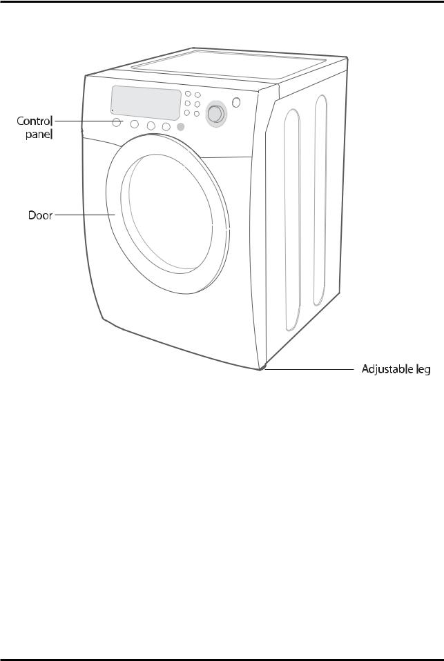
Control
panel
Door |
Adjustable |
|
Adjustable leg
Pliers |
Cutting knife |
Pipe wrench |
Nut drivers |
|
|
(gas only) |
|
Level |
Screwdriver |
Duct tape |
Crescent |
|
(standard) |
|
spanner |
1-6

DUCTING REQUIREMENTS
•Use a 4-inch (10.2 cm) diameter rigid aluminum or rigid galvanized steel duct.
•Do not use a smaller duct.
•Ducts larger than 4 inches (10.2 cm) in diameter can result in increased lint accumulation. Lint accumulation should be cleaned regularly.
•If a flexible metal duct must be used, use the type with a stiff sheet metal wall. Do not use a flexible duct with a thin foil wall. Serious blockage can result if the flexible metal duct is bent too sharply.
•Never install any type of flexible duct in walls, ceilings, or other concealed spaces.
•Keep exhaust duct as straight and short as possible.
•Secure joints with duct tape. Do not use screws.
•DO NOT EXHAUST DRYER INTO ANY WALL, CEILING, CRAWL SPACE, OR CONCEALED SPACE OF A BUILDING, GAS VENT, OR ANY OTHER COMMON DUCT OR CHIMNEY.
THIS COULD CREATE A FIRE HAZARD FROM LINT EXPELLED BY THE DRYER.
•Plastic flexible duct can kink, sag, be punctured, reduce airflow, extend drying times, and affect dryer operation.
•Exhaust systems longer than recommended can extend drying times, affect machine operation, and may collect lint.
•The exhaust duct should end with an exhaust hood with a swing-out damper to prevent back drafts and entry of wildlife. Never use an exhaust hood with a magnetic damper.
•The hood should have at least 12 inches (30.5 cm) of clearance between the bottom of the hood and the ground or other obstruction. The hood opening should point down.
•Never install a screen over the exhaust outlet.
•To avoid lint buildup, do not exhaust the dryer directly into a window well. Do not exhaust under a house or porch.
•If exhaust ductwork must run through an unheated area, the duct should be insulated and slope slightly down towards the exhaust hood to reduce condensation and lint buildup.
•Inspect and clean the interior of the exhaust system at least once a year. Unplug the power cord before cleaning.
•Check frequently to be sure the exhaust hood damper opens and closes freely.
|
|
|
ELECTRIC AND GAS DRYER |
|
|
||||
|
|
|
|
|
|
|
|
|
|
|
|
|
Weather Hood Type |
|
|
||||
|
|
|
|
|
|
|
|
|
|
|
|
Recommended |
Use only for short-run installation |
||||||
|
|
|
|
|
|
|
|
|
|
|
|
|
|
|
|
|
|
||
|
|
|
|
|
|
|
|
||
|
4” (10 .16 |
cm) |
|
|
2.5” (6.35 |
cm) |
|
|
|
|
|
|
|
|
|
||||
|
|
|
|
|
|
|
|
|
|
No. of 90° |
Rigid |
Metallic Flexible* |
Rigid |
|
Metallic Flexible* |
||||
elbows |
|
||||||||
|
|
|
|
|
|
|
|
|
|
0 |
24.4 m (80 ft.) |
12.4 m (41 ft.) |
22.6 m (74 ft.) |
|
10.1 m (33 ft.) |
||||
|
|
|
|
|
|
|
|
|
|
1 |
20.7 m (68 ft.) |
11.2 m (37 ft.) |
18.9 m(62 ft.) |
|
8.8 m (29 ft.) |
||||
|
|
|
|
|
|
|
|
|
|
2 |
17.4 m (57 ft.) |
10.1 m (33 ft.) |
15.5 m(51 ft.) |
|
7.6 m (25 ft.) |
||||
|
|
|
|
|
|
|
|
|
|
3 |
14.3m (47 ft.) |
9.0 m (29 ft.) |
12.5 m(41 ft.) |
|
6.5 m (21 ft.) |
||||
|
|
|
|
|
|
|
|
|
|
* Do not use non-metallic flexible duct.
1-7
If new dryer is installed into an existing exhaust system you must make sure:
•The exhaust system meets all local, state, and national codes.
•That flexible plastic duct is not used.
•Inspect and clean all lint buildup from inside the existing duct.
•The duct is not kinked or crushed.
•The exhaust hood damper opens and closes freely.
The static pressure in any exhaust system must not exceed 0.83 inches of water column, or be less than 0. This can be measured with the dryer running with a manometer at the point where the exhaust duct connects to the dryer. A no-heat setting should be used. The dryer tumbler shoul
REMOVE THE DOOR FROM ALL DISCARDED APPLIANCES TO AVOID THE DANGER OF A CHILD
SUFFOCATING.
LOCATION CONSIDERATIONS
The dryer should be located where there is enough space in front for loading the dryer, and enough space behind for the exhaust system. This dryer is factory-ready for rear exhaust. To exhaust out the bottom or the left, use the accessory exhaust kit. Instructions are included with the kit. It’s important to make sure the room has enough fresh air. The dryer must be located where there is no air-flow obstruction.
On gas dryers, adequate clearance as noted on the data plate must be maintained to ensure adequate air for combustion and proper dryer operation.
THE DRYER MUST NOT BE INSTALLED OR STORED IN AN AREA WHERE IT WILL BE EXPOSED TO WATER AND/OR WEATHER. THE DRYER AREA IS TO BE KEPT CLEAR OF COMBUSTIBLE MATERIALS, GASOLINE, AND OTHER FLAMMABLE VAPORS AND LIQUIDS. A DRYER PRODUCES COMBUSTIBLE LINT. THE AREA AROUND THE DRYER SHOULD BE KEPT LINT-FREE.
ALCOVE OR CLOSET INSTALLATION
WARNING – The dryer must be exhausted to the outside to reduce the risk of fire when  installed in an alcove or closet.
•No other fuel-burning appliance should be installed in the same closet as the dryer.
•WARNING: To reduce the risk of fire, this dryer MUST BE EXHAUSTED TO THE OUTDOORS. See EXHAUST INFORMATION section.
•Minimum clearances between the dryer and adjacent walls or other surfaces are: 2” in front, 17” on top, 1” on either side, and 2.375” in the back.
•Closet front must have two unobstructed air openings for a combined minimum total area of
72 in² with 3” minimum clearance on the top and bottom. A louvered door with equivalent space clearance is acceptable.
1-8

MOBILE HOME INSTALLATION
The installation of the dryer in mobile homes must conform to the Manufactured Home Construction and Safety Standard Title 24 CFR, Part 32-80 {formerly the Federal Standard for Mobile Home Construction and Safety, Title 24, HUD (Part 280), 1975} for the United States) or CSA Standards Z240 (for Canada).
When installing a dryer in a mobile home, provisions for anchoring the dryer to the floor must be made. Locate in an area that has adequate fresh air.
A minimum of 72 in² (183 cm² ) of unobstructed space is required.
All mobile home installations must be exhausted to the outside with the exhaust duct termination securely fastened to the mobile home structure, using materials that will not support combustion.
The exhaust duct may not terminate underneath the mobile home. See Exhausting section for more information.
EXHAUSTING
Exhausting the dryer to the outside will prevent large amounts of lint and moisture from being blown into the room.
In the United States:
•All dryers must be exhausted to the outside.
•Only rigid or flexible metal duct should be used for exhausting.
In Canada:
•All dryers must be exhausted to the outside.
Outside the U.S. and Canada:
•Refer to local codes.
 WARNING –The dryer must be exhausted to the outside to reduce the risk of fire when installed n an alcove or closet.
NEVER USE PLASTIC OR NON-METAL FLEXIBLE DUCT.
If your existing ductwork is plastic, non-metal, or combustible, replace it with metal. Use only metal exhaust duct that is non-flammable to ensure containment of exhaust air, heat, and lint.
1-9

GAS REQUIREMENTS
Use only natural or LP (liquid propane) gases.
THE INSTALLATION MUST CONFORM WITH LOCAL CODES, OR IN THE ABSENCE OF LOCAL CODES, WITH THE NATIONAL FUEL GAS CODE ANSI/Z223.1, LATEST REVISION (FOR THE UNITED STATES), OR WITH THE CAN/CGA-B149 INSTALLATION CODES (FOR CANADA).
Gas dryers are equipped with a burner vent for use with natural gas. If you plan to use your dryer with LP (liquid propane) gas, it must be converted for safe and proper performance by a qualified service technician. A 1/2” (1.27 cm) gas supply line is recommended and must be reduced to connect to the 3/8” (1 cm) gas line on your dryer. The National Fuel Gas Code requires that an accessible, approved manual gas shut-off valve be installed within 6’ of your dryer.
Gas dryers installed in residential garages must be raised 18 inches (46 cm) above the floor.
Additionally, a 1/8” (0.3 cm) N.P.T. (National Pipe Thread) plugged tapping, accessible for test gauge connection, must be installed immediately upstream of your dryer’s gas supply connection.
Your dryer must be disconnected from the gas supply pipe system during any pressure testing of the system.
DO NOT reuse old flexible metal gas lines. Flexible gas lines must be design certified by the American Gas Association (CGA in Canada).
NOTE: • Any pipe joint compound used must be resistant to the action of any liquefied petroleum gas.
• As a courtesy, most local gas utilities will inspect a gas appliance installation.
GAS IGNITION – Your dryer uses an automatic ignition system to ignite the burner. There is no constant burning pilot.
COMMONWEALTH OF MASSACHUSETTS INSTALLATION INSTRUCTIONS
Your dryer must be installed by a licensed plumber or gas fitter. A “T” handle manual gas valve must be installed in the gas supply line to your dryer. If a flexible gas connector is used to install your dryer, the connector must have a maximum length of 3’ (36”).
WARNING – Gas leaks may occur in your system, creating a dangerous situation. Gas leaks may not be detected by smell alone.
Gas suppliers recommend you purchase and install a UL-approved gas detector. Install and use in accordance with manufacturer’s instructions.
1-10

ELECTRICAL REQUIREMENTS
NOTE: Wiring diagram is located on plate below the control panel.
WARNING –
•Improper connection of the equipment grounding conductor can result in a risk of electric shock. Check with a qualified electrician or serviceman if you are in doubt as to whether your dryer is properly grounded. Do not modify the plug provided with your dryer – if it doesn’t fit the outlet, have a proper outlet installed by a qualified electrician.
•To prevent unnecessary risk of fire, electrical shock, or personal injury, all wiring and grounding must be done in accordance with local codes, or in the absence of local codes, with the National Electrical Code, ANSI/NFPA No. 70-Latest Revision (for the U.S.) or the Canadian Electrical Code CSA C22.1 – Latest Revisions and local codes and ordinances. It is your responsibility to provide adequate electrical services for your dryer.
•All gas installations must be done in accordance with the national Fuel Code ANSI/Z2231 – Lastest Revision (for the U.S.) or CAN/CGA – B149 Installation Codes – Latest Revision (for Canada) and local codes and ordinances.
GROUNDING
This dryer must be grounded. In the event of malfunction or breakdown, the ground will reduce the risk of electrical shock by providing a path of least resistance for electrical current.
GAS MODELS
Your dryer has a cord with an equipment-grounding conductor and a grounding plug.
The plug must be plugged into an appropriate outlet that is properly installed and grounded in accordance with all local codes and ordinances.
Do not modify the plug provided with your dryer – if it doesn’t fit the outlet, have a proper outlet installed by a qualified electrician.
NEVER CONNECT GROUND WIRE TO PLASTIC PLUMBING LINES, GAS LINES, OR HOT WATER PIPES.
ELECTRIC MODELS
Your dryer has a cord with an equipment-grounding conductor and a grounding plug.
The plug must be plugged into an appropriate outlet that is properly installed and grounded in accordance with all local codes and ordinances.
If a power cord is not used and the electric dryer is to be permanently wired, the dryer must be connected to a permanent grounded metal wiring system, or an equipment grounding conductor must be run with the circuit conductors and connected to the equipment grounding terminal.
1-11

ELECTRICAL CONNE CTIONS
Before operating or testing, follow all grounding instructions in the Grounding section.
An individual branch (or separate) circuit serving only your dryer is recommended. DO NOT USE AN EXTENSION CORD.
GAS MODELS – U.S. and Canada
A 120 volt, 60 Hz AC approved electrical service, with a 15-ampere fuse or circuit breaker is required.
ELECTRIC MODELS – U.S. Only
Most U.S. dryers require a 120/240 volt, 60 Hz AC approved electrical service. Some require 120/208 volt, 60 Hz approved electrical service. The electric service requirements can be found on the data label located behind the door. A 30-ampere fuse or circuit breaker on both sides of the line is required.
•If a power cord is used, the cord should be plugged into a 30-ampere receptacle.
•The power cord is NOT provided with U.S. electric model dryers.
IMPORTANT:
When local codes allow, the dryer electrical supply may be connected by means of a new power supply cord kit, marked for use with a dryer, that is U.L. listed and rated at a minimum of120/240 volts, 30ampere with three No. 10 copper wire conductors terminated with closed loop terminals, open-end spade lugs with turned up ends, or with tinned leads.
1.size of the conductors and the type of cord.
2.3/4” (1.9 cm) UL-listed strain relief
•Do not reuse a power supply cord from an old dryer. The power cord electric supply wiring must be retained at the dryer cabinet with a suitable UL-listed strain relief.
•Grounding through the neutral conductor is prohibited for (1) new branch-circuit installations,
(2)mobile homes, (3) recreational vehicles, and (4) areas where local codes prohibit grounding through the neutral conductor. (Use 4-prong plug for 4 wire receptacle, NEMA type 14-30R.)
ELECTRIC MODELS – Canada Only
•A 120/240 volt, 60 Hz AC approved electrical service fused through a 30-ampere fuse or circuit breaker on both sides of the line is required.
•All Canadian models are shipped with the power cord attached. The power cord should be plugged into a 30-ampere receptacle.
NOTE: It is not permissible to convert a dryer in Canada to 208 volts.
REPLACEMENT PARTS AND ACCESSORIES
If your dryer requires replacement parts or accessories, contact the dealer from whom you purchased your dryer or a SAMSUNG customer care center at 1-800-SAMSUNG (726-7864).
1-12

INSTALLATION
Parts and literature are packaged inside your dryer drum. To install:
1.Move your dryer to an appropriate location for installation. Consider installing the dryer and washer side-by-side, to allow access to gas, electrical, and exhaust connections.
Lay two of the carton cushion-tops on the floor. Tip your dryer on its side so it will lay across both cushion-tops.
2.Set your dryer back in an upright position.
3.Review the Exhausting section before installing the exhaust system. Install the ductwork from your dryer to the exhaust hood. The crimped end of the duct sections must point away from your dryer.
DO NOT use sheet metal screws when assembling ducting. These joints should be taped.
Never use plastic flexible exhaust material.
Tip for tight installations: install a section of exhaust system to your dryer before putting it in place.
Use duct tape to secure this section to your dryer, but do not cover louvers in dryer cabinet.
4. Review Electrical Requirements section.
BEFORE OPERATING OR TESTING, follow the grounding instructions in the Grounding section.
U.S. MODELS:
IMPORTANT – All U.S. models are produced for a 3-WIRE SYSTEM CONNECTION. The dryer frame is grounded to the neutral conductor at the terminal block.
A 4-WIRE SYSTEM CONNECTION is required for new or remodeled construction, mobile homes,
or if local codes do not permit grounding through neutral. If the 4-wire system is used, the dryer frame cannot be grounded to the neutral conductor at the terminal block. Refer to the following instructions for 3- and 4-WIRE SYSTEM CONNECTIONS.
Remove the terminal block cover plate.
Insert the power cord with a UL-listed strain relief through the hole provided in the cabinet near the terminal block. NOTE: A strain relief must be used.
Do not loosen the nuts already installed on the terminal block. Be sure they are tight. Use a 3/8” (1cm) deep well socket.
5. Review Gas Requirements section. Remove the pipe thread protective cap.
Apply pipe joint compound or about 1 1/2 wraps of Teflon tape over all threaded connections. NOTE: Pipe joint compound must be resistant to the action of any liquefied petroleum gas.
Connect the gas supply to your dryer.
An additional fitting is required to connect the 3/4” (1.9 cm) female thread end of a flexible connector to the 3/8” (1 cm) male threaded end on the dryer.
Securely tighten the gas line fitting over threads.
Turn on the gas supply. Check all gas connections for leaks using a soap solution. If bubbles appear, tighten the connections and recheck.
DO NOT use an open flame to check for gas leaks.
1-13
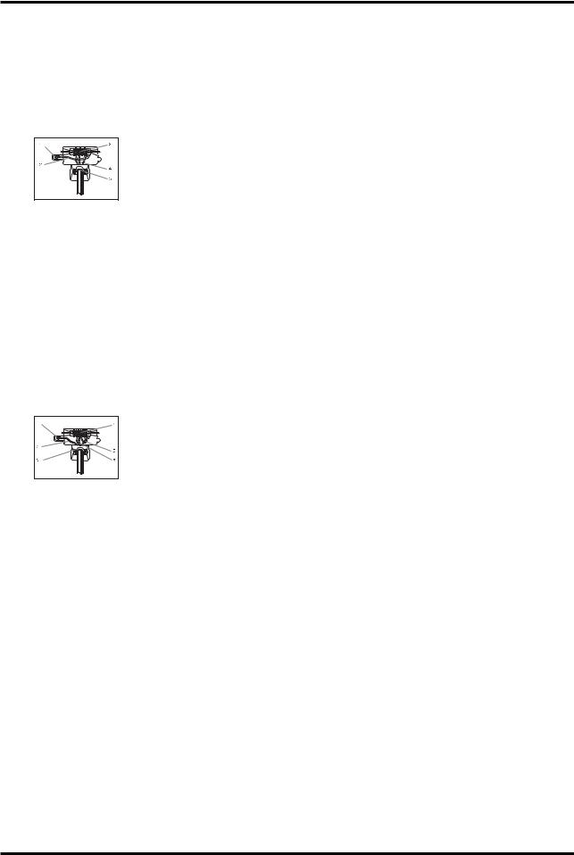
3-WIRE SYSTEM CONNECTIONS
1.Loosen or remove center terminal block screw.
2.Connect neutral wire (white or center wire) of the power cord to the center, silver-colored terminal screw of the terminal block. Tighten screw.
3.Connect the other wires to outer terminal block screws. Tighten screws.
4.Tighten strain relief screws.
5.Insert tab of terminal block cover into your dryer’s rear panel slot. Secure cover with hold-down screw.
•External ground connector
• Neutral grounding wire (green/yellow)
• Center silver-colored terminal block screw
• Neutral wire (white or center wire)
• 3/4” (1.9 cm) UL-listed strain relief
WARNING: If converting from a 4-wire electrical system to a 3-wire, the ground strap must be reconnected to the terminal block support to ground the dryer frame to the neutral conductor.
4-WIRE SYSTEM CONNECTIONS
1.Remove center terminal block screw.
2.Connect ground wire (green or unwrapped) of power cord to external ground conductor screw.
3.Connect neutral wire (white or center wire) of power cord and appliance ground wire (green with yellow stripes) under central screw of the terminal block.
4.Connect the other wires to outer terminal block screws. Tighten screws.
5.Tighten strain relief screws.
6.Insert tab of terminal block cover into your dryer’s rear panel slot.
Secure cover with hold-down screw.
• External ground connector
• Green or bare copper wire of power cord
• 3/4 in. (1.9 cm) UL-listed strain relief
• Center silver-colored terminal block screw
•Grounding wire (green/yellow)
•Neutral wire (white or center wire)
6.With a level, check your dryer and make necessary adjustments to the leveling legs.
7.At this time, make sure all gas connections (on gas models), exhaust and electrical connections are complete. Plug in your dryer, and check operation by using the checklist below.
8.(GAS MODELS ONLY)
The burner may not ignite initially due to air in the gas line. Allowing your dryer to operate on a heat setting will purge the line. If the gas does not ignite within 5 minutes, turn your dryer off and wait
5 minutes. Be sure the gas supply to your dryer has been turned on. In order to confirm gas ignition, check the exhaust for heat.
FINAL INSTALLATION CHECKLIST
□Dryer is plugged into electrical outlet and properly grounded.
□Exhaust ductwork is hooked up and joints taped.
□Plastic flexible duct is NOT used.
□Use rigid or stiff-walled flexible metal vent material.
□Dryer is level with all legs firmly on the floor.
□Gas models – gas is turned on with no gas leaks.
□Start your dryer to confirm that it runs, heats, and shuts off.
1-14
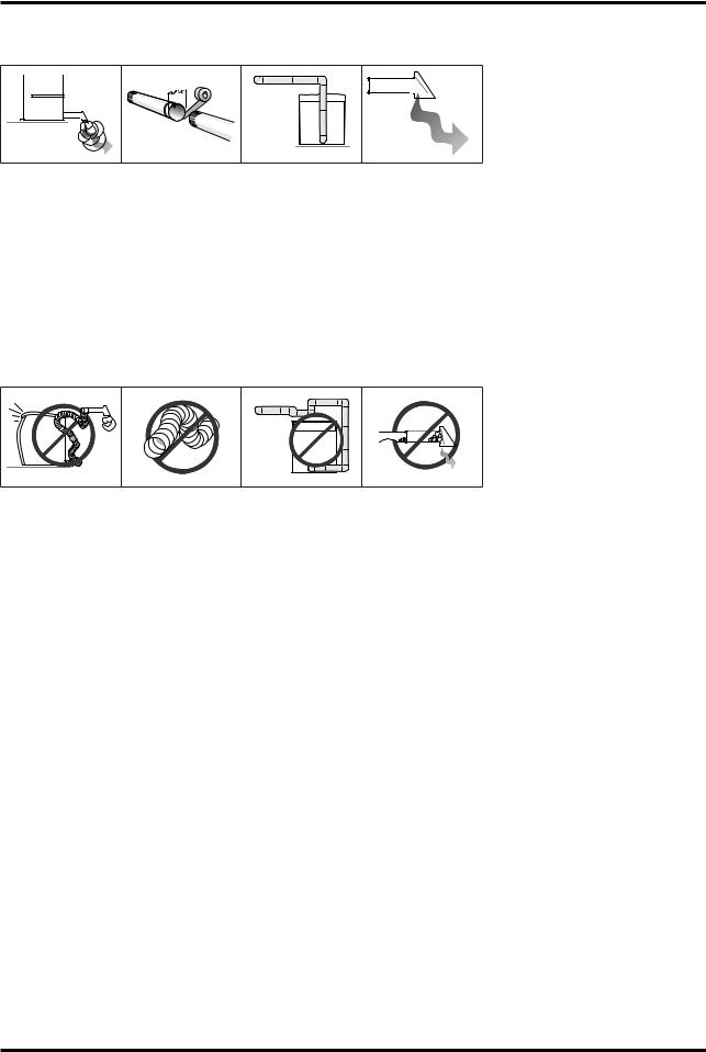
Dryer Exhaust Tips
WARNING: Plastic or non-metal flexible duct presents a potential fire hazard.
1.Let your dryer exhaust the air easily.
2.Use 4” diameter rigid metal duct.Tape all joints, including at the dryer. Never use lint-trapping screws.
3.Keep ducts as straight as possible.
4.Clean all old ducts before installing your new dryer. Be sure vent flap opens and closes freely.
Inspect and clean the exhaust system annually.
Don’t let a poor exhaust system slow drying by:
1.Restricting your dryer with a poor exhaust system.
2.Using a plastic, thin foil, or non-metal flexible duct.
3.Using unnecessarily long duct runs with many elbows.
4.Allowing crushed or clogged ducts and vent.
1-15

Door Reversal
1. |
Unplug power cord. |
6. |
Place the door on the other |
2. |
Remove two door hinge |
|
side and reattach it to dryer. |
|
|
||
|
screws. |
|
|
3. |
Lift the door and remove |
|
|
|
from |
|
|
|
dryer. |
|
|
4. |
Remove two screws on the |
7. |
Reassemble holder lever. |
|
opposite side of door hinge. |
|
|
5. Remove two screws on holder |
8. Reassemble the screws in |
lever. |
the |
|
remaining holes. |
1-16

51#SURGXFW#VSHFLILFDWLRQV
5041#WKH#IHDWXUH#RI#SURGXFW
Concept
-Super Size Capacity
-Energy Saving
-Time Saving
Main Feature
-7.3 cu.ft.
-Energy Saving(3200 Wh/Cycle)
-Time Saving (Normal Course 44 min.)
Sub. Feature
-Fuzzy Algorithm
-Easy Reversible Door
-Slanted control panel
2-1

5051#VSHFLILFDWLRQV#RI#SURGXFW
ZDVK#W\SH |
|
|
IURQW#ORDGLQJ#W\SH |
|
|||
|
|
|
|
|
|
|
|
|
Div |
|
Inches (cm) |
|
Div |
|
Inches (cm) |
|
|
|
|
|
|
|
|
|
A. Height |
|
38”(96.5) |
|
C. Depth with |
|
49”(124.5) |
|
|
|
door open 90° |
|
|||
GLPHQVLRQ |
|
|
|
|
|
|
|
|
|
|
|
|
|
|
|
B. Width |
|
27”(68.6) |
|
D. Depth |
|
30.25” (77.0) |
|
|
|
|
|
||||
|
|
|
|
|
|
|
|
ZHLJKW |
|
|
|
56.8kg |
|
||
|
|
|
|
|
|
||
KHDWHU#UDWLQJ |
|
|
|
5300W |
|
||
|
|
|
|
|
|
||
|
NO HEAT |
|
|
268W |
|
||
SRZHU#FRQVXPSWLRQ |
|
|
|
|
|
|
|
HEATING |
|
|
5445W |
|
|||
|
|
|
|
||||
|
|
|
|
|
|
|
|
2-2
5061#RYHUYLHZ#RI#WKH#GU\HU
2-3

5071#WKH#FRPSDUDWLYH#VSHFLILFDWLRQV#RI#SURGXFW
Ghvljq |
|
|
|
|
|
Prgho |
DV316LG |
Frontier Dryer |
|
|
|
Fdsdflw| |
7.3 |
7.3 |
|
|
|
Grru#W|sh |
Glass Transparent |
Glass Transparent |
|
|
|
Yhqw#H{kdxvw |
E/G, 3 way |
E/G, 3 way |
|
|
|
Khdwlqj#Hohphqw#+NZ, |
5300W / 22,000 BTU/hr |
5300W / 22,000 BTU/hr |
|
|
|
Yrowdjh#2#Iuhtxhqf| |
240V/60Hz |
240V/60Hz |
|
|
|
ri#Gu|lqj#F|foh |
9 |
9 |
|
|
|
Qrupdo |
Yes |
Yes |
|
|
|
Khdy|#Gxw| |
Yes |
Yes |
|
|
|
Wrzhov |
Yes |
Yes |
|
|
|
Shup#Suhvv |
Yes |
Yes |
|
|
|
Gholfdwhv |
Yes |
Yes |
|
|
|
Iuhvkhq#Xs |
Yes |
Yes |
|
|
|
Wlph#Gu| |
Yes |
Yes |
|
|
|
Zulqnoh#Uhohdvh |
Yes |
Yes |
|
|
|
Dlu#Ioxii |
Yes |
Yes |
|
|
|
ri#Rswlrq |
3 |
3 |
|
|
|
P|#F|foh |
Yes |
Yes |
|
|
|
Udfn#Gu| |
Yes |
Yes |
|
|
|
Zulqnoh#Suhyhqw |
Yes |
Yes |
|
|
|
ri##Whps#Ohyho |
5 |
5 |
|
|
|
Kljk |
Yes |
Yes |
|
|
|
Phglxp |
Yes |
Yes |
|
|
|
Phglxp#Orz |
Yes |
Yes |
|
|
|
Orz |
Yes |
Yes |
|
|
|
H{wud#Orz |
Yes |
Yes |
|
|
|
ri#Gu|qhvv#Ohyho |
5 |
5 |
|
|
|
Yhu|#Gu| |
Yes |
Yes |
|
|
|
Pruh#Gu| |
Yes |
Yes |
|
|
|
Qrupdo#Gu| |
Yes |
Yes |
|
|
|
Gdps#Gu| |
Yes |
Yes |
|
|
|
Vrxqg#Ohyho |
Louder/Softer/Off |
Louder/Softer/Off |
|
|
|
Dgmxvw#Wlph |
Up/Down |
Up/Down |
|
|
|
Glphqvlrq#+K#{#Z#{#G, |
38” x 27 x 31 |
38” x 27 x 31 |
|
|
|
2-4
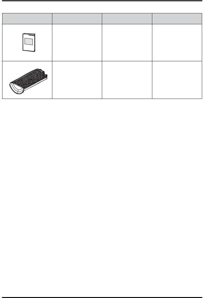
5071#RSWLRQ#VSHFLILFDWLRQV
Lwhp |
Lwhp#Qdph |
FRGH1QR |
Uhpdun |
MANUAL-BOOK DC68-02312A
DIE-RACK DRY |
DC61-01522A |
2-5

Memo
2-6
61#RSHUUDWLQJ#LQVWDOODWLRQV#DQG#LQVWDOODWLRQ
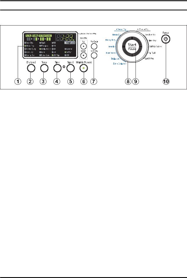
6041#RYHUYLHZ#RI#WKH#FRQWURO#SDQHO
1. Digital Graphic Display
The display window shows the estimated time remaining in the cycle after the Cycle Selector dial is pressed. The estimated time remaining may fluctuate as the cycle progresses.
The Drying light will illuminate and remain lit until the cycle is complete. When your dryer is in the cool-down phase, the Cooling light will illuminate.
When your dryer is in the wrinkle prevent phase, the Wrinkle Prevent light will illuminate.
When the cycle is complete, “END” will appear in the display panel until the dryer door is opened or Power key is pushed.
If your dryer is paused during a cycle, the indicator lights will blink until the Cycle Selector dial is pressed.
2. Dry Level Selection Button
To select the dry level in the Normal, Heavy Duty, or other Sensor Dry cycles, press the Dry Level button. An indicator light will illuminate next to the desired dryness level.
Press the button repeatedly to scroll through the settings. Larger or bulkier loads may require the Very Dry (select models) or More Dry setting for complete dryness.
The Less Dry setting is best suited for lightweight fabrics or for leaving some moisture in the clothing at the end of the cycle. Damp Dry (select models) is designed to partially dry items.
Use for items that lay flat or hang to dry.
3. Temp Selection Button
To select the correct temperature for the load, press the Temp button. An indicator light will illuminate next to the desired temperature. Press the button repeatedly to scroll through the settings.
Kljk – For sturdy cottons or those labeled Tumble Dry.
Phglxp – For permanent press, synthetics, lightweight cottons, or items labeled Tumble Dry Medium. Phglxp#Orz – For lower heat than Medium to dry synthetic or washable knit fabrics.
Orz#– For heat sensitive items labeled Tumble Dry Low or Tumble Dry Warm. H{wud#Orz – Provides the lowest heated dry temperature possible.
4. Time Selection Button
When using Manual Dry cycles, time can be adjusted by pressing time selection button. During the Sensory Dry cycle, the time light indicator is off because exact drying times are determined by fluctuating humidity levels.
3-1
 Loading...