


DV50K8600EV/A3
Table of contents
 Loading...
Dryer
User manual
DV50K8600E(G)*
DV8700K-03170T-00_EN (US)_151130.indd 1 2015-11-30 12:26:40
Contents
English2
Contents
Safety information 4
What you need to know about the safety instructions 4
Important safety symbols 4
Important safety precautions 5
Warnings 7
Cautions 8
Installation requirements 10
Key installation requirements 10
Location considerations 10
Ducting requirements 11
Exhausting requirements 12
Gas requirements 13
Electrical requirements 14
Installation 16
What’s included 16
Step-by-step installation 18
Vent blockage test 24
Exhaust ducting guide 25
Switching the door position 26
Before you start 29
Sort and load 29
Functional prerequisite 29
Operations 30
Feature panel 30
Simple steps to start 33
Cycle overview 34
Drying guide 35
Special features 36
DV8700K-03170T-00_EN (US)_151130.indd 2 2015-11-30 12:26:41
Contents
English 3
Maintenance 38
Vent sensor 38
Cleaning 39
Troubleshooting 40
Checkpoints 40
Information codes 43
Specications 44
Fabric care chart 44
Protecting the environment 45
Specication sheet 46
Cycle chart 47
DV8700K-03170T-00_EN (US)_151130.indd 3 2015-11-30 12:26:41

Safety information
SAVE THESE INSTRUCTIONS
English4
Safety information
Congratulations on your new Samsung dryer. This manual contains important information
on the installation, use and care of your appliance. Please take some time to read this
manual to take full advantage of your dryer’s many benets and features.
What you need to know about the safety instructions
Please read this manual thoroughly to ensure that you know how to safely and efciently
operate the extensive features and functions of your new appliance. Please store the
manual in a safe location close to the appliance for future reference. Use this appliance
only for its intended purpose as described in this instruction manual.
Warnings and Important Safety Instructions in this manual do not cover all possible
conditions and situations that may occur. It is your responsibility to use common sense,
caution and care when installing, maintaining and operating your dryer.
Because the following operating instructions cover various models, the characteristics of
your dryer may differ slightly from those described in this manual and not all warning
signs may be applicable. If you have any questions or concerns, contact your nearest
service center or nd help and information online at www.samsung.com.
Important safety symbols
What the icons and signs in this user manual mean:
WARNING
Hazards or unsafe practices that may result in severe personal injury, death and/or
property damage.
CAUTION
Hazards or unsafe practices that may result in personal injury and/or property damage.
NOTE
Indicates that a risk of personal injury or material damage exists.
These warning signs are here to prevent injury to yourself and others.
Please follow them explicitly.
After reading this manual, store it in a safe place for future reference.
Read all instructions before using the appliance.
As with any equipment that uses electricity and moving parts, potential hazards exist.
To safely operate this appliance, familiarize yourself with its operation and exercise care
when using it.
DV8700K-03170T-00_EN (US)_151130.indd 4 2015-11-30 12:26:41
Safety information
SAVE THESE INSTRUCTIONSSAVE THESE INSTRUCTIONS
English 5
WARNING - Gas Appliances:
• State of California Proposition 65 Warning (US only)
This product contains chemicals known to the State of California to cause cancer and
birth defects or other reproductive harm.
• Gas appliances can cause low-level exposure to Proposition 65 listed substances,
including but not limited to, benzene, carbon monoxide, formaldehyde and soot,
substances resulting from the incomplete combustion of natural gas or LP fuels.
WARNING - Risk of Fire
• Clothes dryer installation must be performed by a qualied installer.
• Install the clothes dryer according to the manufacturer’s instructions and local codes.
• Do not install a clothes dryer with exible plastic venting materials. If exible metal
(foil type) duct is installed, it must be of a specic type identied by the appliance
manufacturer as suitable for use with clothes dryers. Flexible venting materials are
known to collapse, be easily crushed, and trap lint. These conditions will obstruct
clothes dryer airow and increase the risk of re.
• To reduce the risk of severe injury or death, follow all installation instructions.
• Save these instructions.
Important safety precautions
WARNING
To reduce the risk of re, electric shock, or injury to persons when using your appliance,
follow basic precautions, including the following:
1. Read all instructions before using this appliance.
2. Do not dry articles that have been previously cleaned in, washed in, soaked in,
or spotted with gasoline, dry-cleaning solvents, or other ammable or explosive
substances, as they give off vapors that could ignite or explode.
3. Do not use the dryer to dry clothes which have traces of any ammable substance,
such as vegetable oil, cooking oil, machine oil, ammable chemicals, paint thinner, etc.,
or anything containing wax or chemicals, such as mops and cleaning cloths. Flammable
substances may cause the fabric to catch re by itself.
4. Do not store or use gasoline or other ammable vapors and liquids near this or any
other appliance.
DV8700K-03170T-00_EN (US)_151130.indd 5 2015-11-30 12:26:41

Safety information
SAVE THESE INSTRUCTIONS
Safety information
SAVE THESE INSTRUCTIONS
English6
5. Do not allow children to play on or in the appliance. Close supervision of children is
necessary when the appliance is used near children.
6. Before the appliance is removed from service or discarded, remove the door to the
drying compartment.
7. Do not reach into the appliance if the drum is moving.
8. Do not install or store this appliance where it will be exposed to the weather.
9. Do not tamper with internal controls.
10. Do not repair or replace any part of the appliance or attempt any service unless
specically recommended in the user-maintenance instructions or in published user-
repair instructions that you understand and have the skills to carry out.
11. Do not use fabric softeners or products to eliminate static unless recommended by the
manufacturer of the fabric softener or product.
12. Clean the lint screen before or after each load.
13. Do not use heat to dry articles containing foam rubber or similarly textured rubber-like
materials.
14. Keep area around the exhaust opening and adjacent surrounding areas free from the
accumulation of lint, dust, and dirt.
15. The interior of the appliance and exhaust duct should be cleaned periodically by
qualied service personnel.
16. Do not place items exposed to cooking oils in your dryer. Items contaminated with
cooking oils may contribute to a chemical reaction that could cause a load to catch re.
17. This appliance must be grounded. See “Electrical requirements” and ”Grounding” in
“Installation” section.
18. Do not allow children to play on or in the appliance. Close supervision of children is
necessary when the appliance is used near children.
19. Do not insert your hand under the dryer.
• This may result in injury.
20. Take care that children’s ngers are not caught in the door when closing it.
• This may result in injury.
21. The control board and inlet valve are intentionally not grounded and may present a
risk of electric shock only during servicing.
• Do not contact these parts while the appliance is energized.
DV8700K-03170T-00_EN (US)_151130.indd 6 2015-11-30 12:26:41
Safety information
SAVE THESE INSTRUCTIONSSAVE THESE INSTRUCTIONS
English 7
WARNING - To reduce the risk of re or explosion:
• Do not dry items that have been previously cleaned, washed, soaked, or spotted with
gasoline, dry cleaning solvents, or other ammable or explosive substances. They
emit vapors that could ignite or explode. Any material that has been in contact with a
cleaning solvent or ammable liquids or solids should not be placed in the dryer until
all traces of these ammable liquids or solids and their fumes have been removed.
There are many highly ammable items used in homes, such as acetone, denatured
alcohol, gasoline, kerosene, some liquid household cleaners, some spot removers,
turpentine, waxes, and wax removers.
• Items containing foam rubber (may be labeled latex foam) or similarly textured
rubberlike materials must not be dried on a heat setting. Heated foam rubber
materials can, under certain circumstances, ignite spontaneously.
WARNING - What to do if you smell gas:
• Do not try to light any appliance.
• Do not turn on the appliance.
• Do not touch any electrical switch.
• Do not use any phone in your building.
• Clear the room, building or area of all occupants.
• Immediately call your gas supplier from a neighbor’s phone. Follow the gas supplier’s
instructions.
• If you cannot reach your gas supplier, call the re department.
• Installation and service must be performed by a qualied installer, service agency, or
the gas supplier.
Warnings
WARNING
• Ensure pockets are free of small, irregularly shaped hard objects and foreign material,
i.e. coins, knives, pins, etc. These objects could damage your dryer.
• Gas leaks may occur in your system, resulting in a dangerous situation.
DV8700K-03170T-00_EN (US)_151130.indd 7 2015-11-30 12:26:41
Safety information
SAVE THESE INSTRUCTIONS
Safety information
SAVE THESE INSTRUCTIONS
English8
Cautions
CAUTION
• Do not allow children or pets to play on, in, or in front of the appliance. Close
supervision is necessary when the appliance is used near children and pets.
• Before discarding or removing your dryer from service, remove the door to the drying
compartment to prevent children or animals from becoming trapped inside.
• Do not reach into the appliance when the drum is moving.
• Do not install or store this appliance where it will be exposed to the weather.
• Do not tamper with the controls.
• Do not repair, replace, or attempt to service any part of the appliance unless
specically instructed to in the user-repair instructions and you have the
understanding and skills to carry out the procedure.
• Do not use fabric softeners or products to eliminate static unless the softener or
product is recommended for dryer use by the manufacturer of the fabric softener or
product.
• Clean the lint screen before or after each load.
• Keep the area around the exhaust opening and surrounding areas free from lint, dust,
and dirt.
• The interior of the dryer and exhaust duct should be cleaned periodically by qualied
service personnel.
• This appliance must be properly grounded. Never plug the power cord into a receptacle
that is not grounded adequately or not in accordance with local and national codes. See
the installation instructions for information about grounding this appliance.
• Do not sit on top of the dryer.
• Do not dry clothing with large buckles, buttons, or other heavy metal or solid objects.
• Gas leaks may not be detected by smell alone.
• Gas suppliers recommend you purchase and install a UL-approved gas detector.
• Install and use in accordance with the manufacturer’s instructions.
• Do not place items in your dryer that have been spotted or soaked with vegetable oil
or cooking oil. Even after being washed, these items may contain signicant amounts
of these oils.
DV8700K-03170T-00_EN (US)_151130.indd 8 2015-11-30 12:26:41

Safety information
SAVE THESE INSTRUCTIONSSAVE THESE INSTRUCTIONS
English 9
• Residual oil on clothing can ignite spontaneoulsy. The potential for spontaneous
combustion increases when items containing vegetable oil or cooking oil are exposed
to heat. Heat sources such as your dryer can warm these items, allowing an oxidation
reaction in the oil to occur. Oxidation creates heat. If this heat cannot escape, the items
can become hot enough to catch re. Piling, stacking, or storing these kinds of items
may prevent heat from escaping and can create a re hazard.
• All washed and unwashed fabrics that contain vegetable oil or cooking oil can be
dangerous.
Washing these items in hot water with extra detergent will reduce, but not eliminate,
the hazard. Always use the Cool Down cycle for these items to reduce their
temperature. Never remove these items from the dryer hot or interrupt the drying
cycle until the items have run through the Cool Down cycle. Never pile or stack these
items when they are hot.
DV8700K-03170T-00_EN (US)_151130.indd 9 2015-11-30 12:26:41
Installation requirements
English10
Installation requirements
Read through the following instructions before installing the dryer, and keep this manual
for future reference.
WARNING
The control board and inlet valve are intentionally not grounded and may present a risk of
electric shock only during servicing.
Service personnel - Do not contact these parts while the appliance is energized.
Key installation requirements
• A grounded electrical outlet.
• A power cord for electric dryers (except
in Canada).
• Gas lines (for gas models) that must
meet national and local regulations.
• An exhaust system made of rigid metal
or exible stiff-walled metal exhaust
ducting.
WARNING
Remove the door from all discarded
appliances to prevent a child from
suffocating.
Location considerations
• Adequate clearances between the dryer
and adjacent walls or other surfaces.
• Adequate air circulation for ventilation
and gas combustion.
• Away from water and weather.
WARNING
• Make sure to exhaust the dryer
outdoors to reduce the risk of re.
• Keep the dryer area clear of
combustible materials, gasoline, and
other ammable vapors and liquids.
• Do not install other fuel-burning
appliances around or in the same place
as the dryer.
Alcove or closet installation
Minimum clearances between the dryer
and adjacent walls or other surfaces are:
2” in front, 17” on top, 1” on either side,
and 5” in the back.
The closet front must have two
unobstructed air openings for a combined
minimum total area of 72 in² with 3”
minimum clearance on the top and bottom.
A louvered door with equivalent space
clearance is acceptable.
DV8700K-03170T-00_EN (US)_151130.indd 10 2015-11-30 12:26:41
Installation requirements
English 11
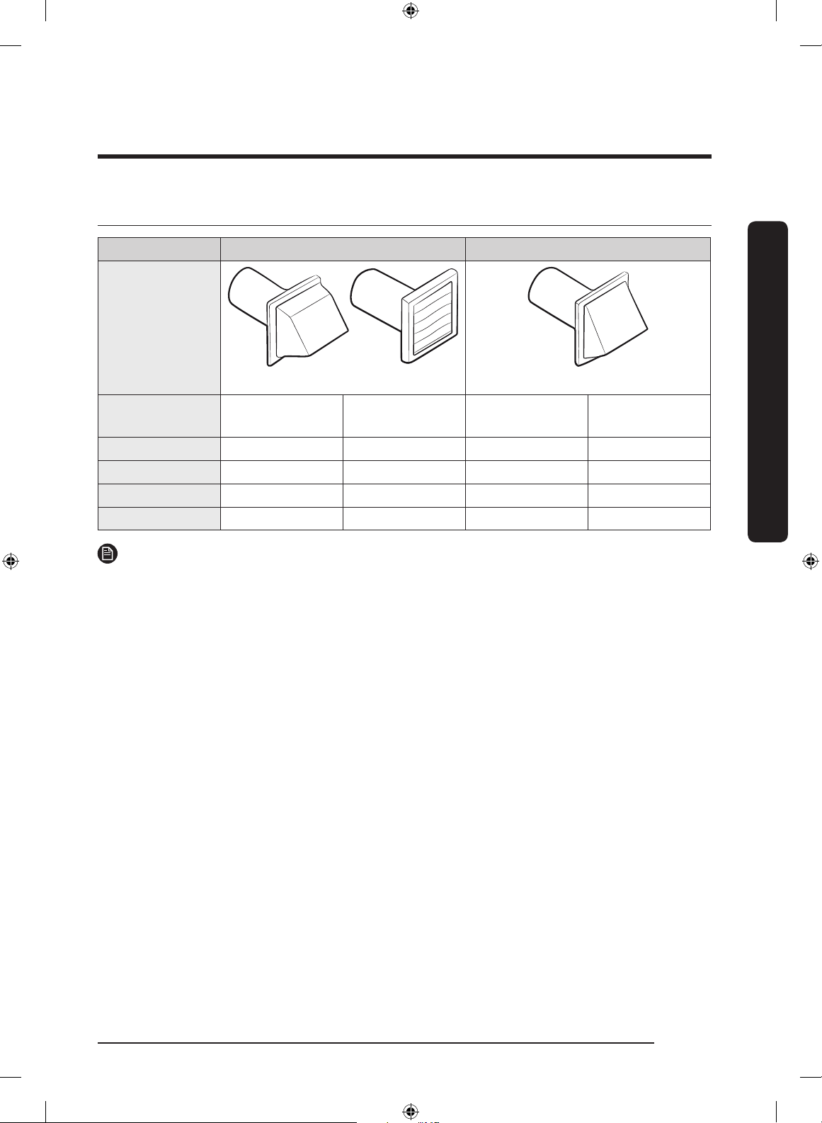
Ducting requirements
Recommended Use only for short-run installation
Weather hood
type
4” (10.2 cm)
2.5” (6.4 cm)
No. of 90°
elbows
Rigid
Metallic
exible*
Rigid
Metallic
exible*
0 80 ft. (24.4 m) 41 ft. (12.4 m) 74 ft. (22.6 m) 33 ft. (10.1 m)
1 68 ft. (20.7 m) 37 ft. (11.2 m) 62 ft. (18.9 m) 29 ft. (8.8 m)
2 57 ft. (17.4 m) 33 ft. (10.1 m) 51 ft. (15.5 m) 25 ft. (7.6 m)
3 47 ft. (14.3 m) 29 ft. (8.8 m) 41 ft. (12.5 m) 21 ft. (6.5 m)
NOTE
* Use a 4-inch (10.2 cm) diameter rigid aluminum or galvanized steel duct.
If you integrate the dryer’s vent system with an existing exhaust system:
• Make sure the exhaust system meets all applicable local, state, and national regulations.
• Verify you are not using exible plastic duct.
• Make sure to check for and remove all lint buildup from inside the existing ducts.
• Conrm the duct is not kinked or crushed.
• Make sure the exhaust hood damper opens and closes freely.
Manometer measurements
The static pressure in any exhaust system must not exceed 0.83 inches of water column
or be less than 0. Note that these values are measured with the dryer running with a
manometer presented to the exhaust duct that connects to the dryer. The dryer tumbler
must be empty and lint lter clean.
DV8700K-03170T-00_EN (US)_151130.indd 11 2015-11-30 12:26:41
Installation requirements
Installation requirements
English12
Exhausting requirements
The dryer must not be exhausted into a
chimney, a wall, a ceiling, an attic, a crawl
space, or a concealed space of a building.
Exhausting the dryer to the outside will
prevent large amounts of lint and moisture
from being blown into the room.
In the United States and Canada
• All dryers must be exhausted to the
outside.
• The required exhaust duct is 4 inches
(10.2 cm) in diameter.
• See “Ducting requirements” in the
“Installation” section for the maximum
duct length and number of bends that
can be used.
• The total length of exible metal duct
must not exceed 7’ 10½” (2.4 m).
• Do not assemble the duct with screws
or other fasteners that extend into the
duct and catch lint.
• For the United States only: Use only
those foil-type exible ducts, if any,
specically identied for use with the
appliance by the manufacturer and that
comply with the Outline for Clothes
Dryer Transition Duct. Use Subject
2158A.
Outside the United States and Canada
• Refer to the local codes.
WARNING
• You must exhaust the dryer to the
outside to reduce the risk of re when
you install the dryer in an alcove or
closet.
• Do not use a plastic or non-metal
exible duct.
• If your existing ductwork is plastic, non-
metal, or combustible, replace it with
metal.
• Use only a metal exhaust duct that is
non-ammable to ensure containment
of exhaust air, heat, and lint.
DV8700K-03170T-00_EN (US)_151130.indd 12 2015-11-30 12:26:41
Installation requirements
English 13
Gas requirements
WARNING
• Use only natural or LP (liquid propane)
gases.
• THE INSTALLATION MUST CONFORM
WITH LOCAL CODES, OR IN THE
ABSENCE OF LOCAL CODES, WITH
THE NATIONAL FUEL GAS CODE ANSI/
Z223.1, LATEST REVISION (FOR THE
UNITED STATES), OR WITH THE CAN /
CGA-B149 INSTALLATION CODES (FOR
CANADA).
• Gas dryers are equipped with a burner
vent for use with natural gas. If you
plan to use your dryer with LP (liquid
propane) gas, it must be converted
for safe and proper performance by a
qualied service technician.
• A 1/2” (1.27 cm) gas supply line is
recommended and must be reduced to
connect to the 3/8” (1 cm) gas line on
your dryer. The National Fuel Gas Code
requires that an accessible, approved
manual gas shut-off valve be installed
within 6” of your dryer.
• Gas dryers installed in residential
garages must be raised 18 inches (46
cm) above the oor.
• Additionally, a 1/8” (0.3 cm) N.P.T.
(National Pipe Thread) plugged tapping,
accessible for test gauge connection,
must be installed immediately upstream
of your dryer’s gas supply connection.
• Your dryer must be disconnected from
the gas supply pipe system during any
pressure testing of the system.
• Do not reuse old exible metal gas
lines. Flexible gas lines must be
design certied by the American Gas
Association (CGA in Canada).
NOTE
• Your dryer uses an automatic ignition
system to ignite the burner. There is no
constant burning pilot.
• Any pipe joint compound used must be
resistant to the action of any liqueed
petroleum gas.
• As a courtesy, most local gas utilities
will inspect a gas appliance installation.
Commonwealth of Massachusetts
installation instructions
Your dryer must be installed by a licensed
plumber or gas tter. A “T” handle manual
gas valve must be installed in the gas
supply line to your dryer. If a exible gas
connector is used to install your dryer, the
connector can be no longer than 3’ (36”).
WARNING
• Gas leaks may occur in your system,
creating a dangerous situation.
• Gas leaks may not be detected by smell
alone.
• Gas suppliers recommend you purchase
and install a UL-approved gas detector.
• Install and use in accordance with the
manufacturer’s instructions.
DV8700K-03170T-00_EN (US)_151130.indd 13 2015-11-30 12:26:42

Installation requirements
Installation requirements
English14
Electrical requirements
The wiring diagram is located on the plate
under the control panel or rear frame.
WARNING
• Improperly connecting the equipment
grounding conductor can result in a
risk of electric shock. Check with a
qualied electrician or serviceman if
you are in doubt as to whether your
dryer is properly grounded. Do not
modify the plug provided with your
dryer – if it doesn’t t the outlet, have
a proper outlet installed by a qualied
electrician.
• To prevent unnecessary risk of re,
electrical shock, or personal injury, all
wiring and grounding must be done in
accordance with local codes, or in the
absence of local codes, in accordance
with the National Electrical Code, ANSI/
NFPA No. 70-Latest Revision (for the
U.S.) or the Canadian Electrical Code CSA
C22.1 – Latest Revisions and local codes
and ordinances. It is your responsibility
to provide adequate electrical service
for your dryer.
• All gas installations must be done in
accordance with the national Fuel Code
ANSI/Z2231 – Latest Revision (for the
U.S.) or CAN/CGA – B149 Installation
Codes – Latest Revision (for Canada)
and local codes and ordinances.
Grounding
This dryer must be grounded. In the event
of a malfunction or breakdown, the ground
will reduce the risk of electrical shock by
providing a path of least resistance for the
electrical current.
Gas models
WARNING
• Your dryer has a cord with an
equipment-grounding conductor and
a grounding plug. The plug must be
plugged into an appropriate outlet that
is properly installed and grounded in
accordance with all local codes and
ordinances.
• Do not modify the plug provided with
your dryer – if it doesn’t’t t the outlet,
have a proper outlet installed by a
qualied electrician.
• Do not connect the ground wire to
plastic plumbing lines, gas lines, or hot
water pipes.
Electric models
WARNING
• Your dryer has an optional cord with
an equipment-grounding conductor
and a grounding plug. This cord is sold
separately.
• The plug must be plugged into an
appropriate outlet that is properly
installed and grounded in accordance
with all local codes and ordinances.
• Do not modify the plug provided with
your dryer – if it doesn’t’t t the outlet,
have a proper outlet installed by a
qualied electrician.
DV8700K-03170T-00_EN (US)_151130.indd 14 2015-11-30 12:26:42
Installation requirements
English 15
• If a power cord is not used and the
electric dryer is to be permanently
wired, the dryer must be connected to
a permanently grounded metal wiring
system, or an equipment grounding
conductor must be run with the circuit
conductors and connected to the
equipment grounding terminal or lead
on the dryer.
Electrical connections
Before operating or testing, follow all
grounding instructions in the “Grounding”
section. An individual branch (or separate)
circuit serving only your dryer is
recommended.
Do not use an extension cord.
Gas models – U.S. and Canada
A 120 volt, 60 Hz AC approved electrical
service with a 15-ampere fuse or circuit
breaker is required.
Electric models – U.S. only
Most U.S. dryers require a 120 / 240 volt,
60 Hz AC approved electrical service.
Some require 120 / 208 volt, 60 Hz
approved electrical service. The electric
service requirements can be found on
the data label located behind the door.
A 30-ampere fuse or circuit breaker on
both sides of the line is required.
• If a power cord is used, the cord
should be plugged into a 30-ampere
receptacle.
• The power cord is not provided with
U.S. electric model dryers. This cord is
sold separately.
WARNING
Risk of Electric Shock
When local codes allow, you can connect
the dryer’s electrical supply with a new
power supply cord kit, marked for use with
a dryer, that is U.L. listed and rated at a
minimum of 120/240 volts, 30-amperes
with three No. 10 copper wire conductors
terminated with closed loop terminals,
open-end spade lugs with turned up ends,
or with tinned leads.
• Do not reuse a power supply cord from
an old dryer. The power cord electric
supply wiring must be supported at the
dryer cabinet by a suitable UL-listed
strain relief.
• Grounding through the neutral
conductor is prohibited for (1) new
branch-circuit installations, (2) mobile
homes, (3) recreational vehicles, and
(4) areas where local codes prohibit
grounding through the neutral
conductor. (Use a 4-prong plug for a
4 wire receptacle, NEMA type 14-30R.)
Electric models – Canada Only
• A 120 / 240 volt, 60 Hz AC approved
electrical service fused through a
30-ampere fuse or circuit breaker on
both sides of the line is required.
• All Canadian models are shipped
with the power cord attached. The
power cord should be plugged into a
30-ampere receptacle.
NOTE
In Canada, you may not convert a dryer to
208 volts.
DV8700K-03170T-00_EN (US)_151130.indd 15 2015-11-30 12:26:42
Installation
English16
Installation
This dryer must be installed by a qualied technician. The installer is responsible for
connecting the dryer to the main power while observing the relevant safety regulations of
your area.
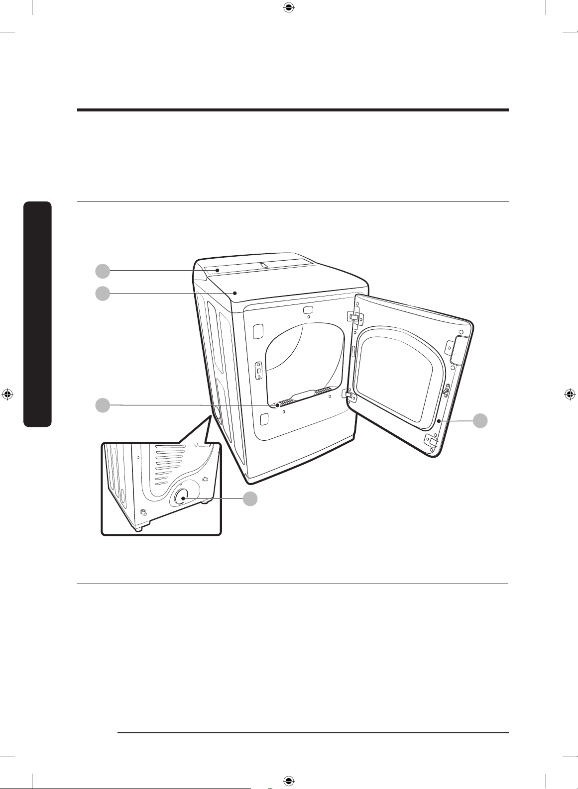
What’s included
Make sure all the parts are included in the product package. If you have a problem with
the dryer or the accessories, contact a local Samsung service center or the retailer.
01
02
04
03
05
Dryer at a glance
01 Control panel 02 Worktop 03 Filter
04 Door 05 Exhaust duct
DV8700K-03170T-00_EN (US)_151130.indd 16 2015-11-30 12:26:42
Installation
English 17
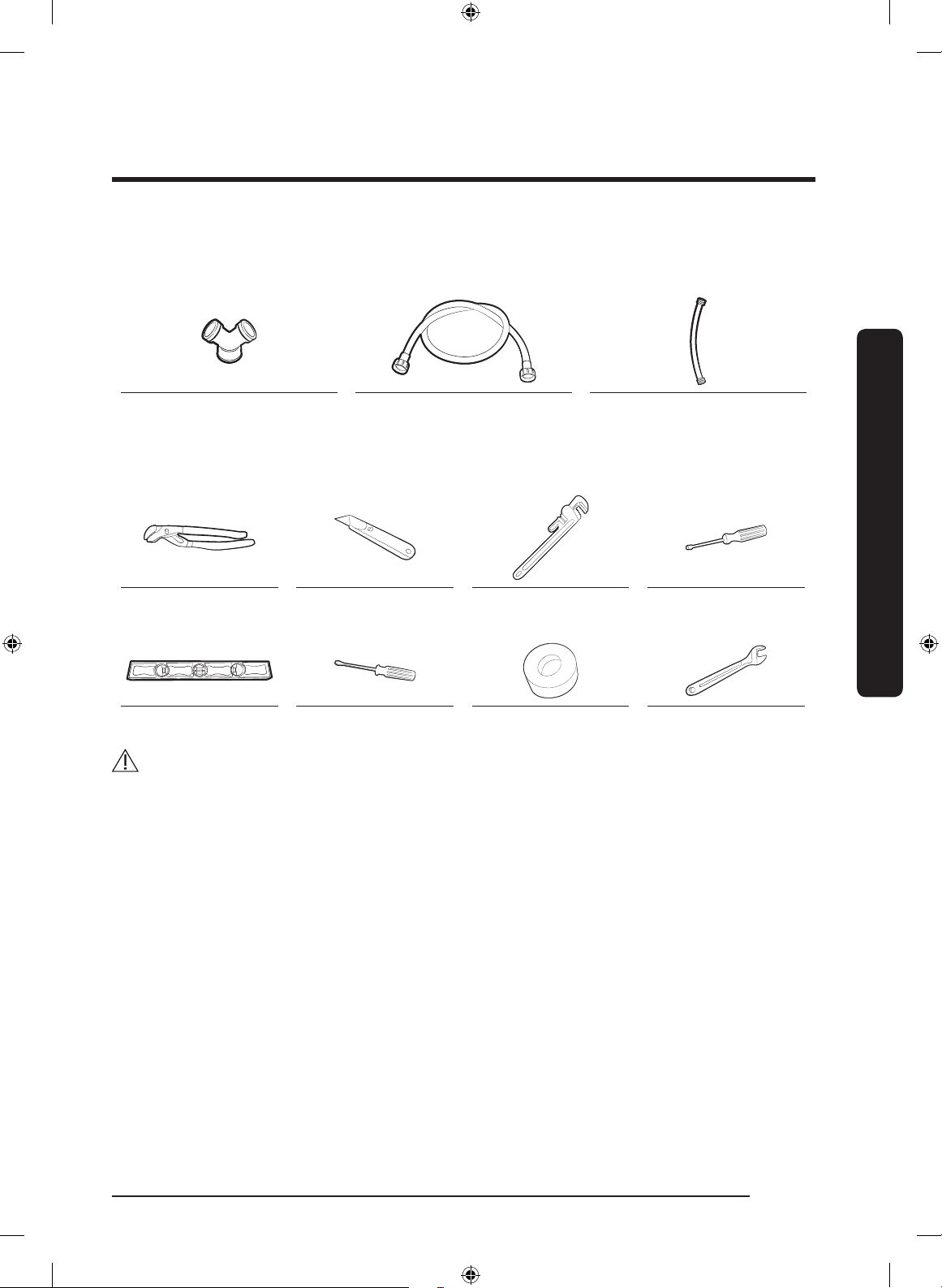
Accessories & tools
Provided accessories
Y connector Water hose
(Canadian models only)
Short water hose
Required tools
Pliers Cutting knife Pipe wrench
(gas models only)
Nut screwdriver
Level Philips screwdriver Duct tape Wrench
WARNING
Packing materials can be dangerous to children. Keep all packing materials (plastic bags,
polystyrene, etc.) out of children’s reach.
DV8700K-03170T-00_EN (US)_151130.indd 17 2015-11-30 12:26:43
Installation
Installation
English18
Step-by-step installation
Make sure you have a qualied technician install the dryer. Step by step installation
instructions start below.
STEP 1 Install the exhaust system
1. Select a location and move the dryer to the site. For easy access, we recommend you
install the dryer in the same location as your washer.
2. To change the door direction, see “Switching the door position”.
3. Install the exhaust system as instructed in the “Exhaust ducting guide” section.
NOTE
• To move the dryer easily, lay two of the carton cushions from the packaging on the
oor. Tip the dryer on its side so it lies across both cushion-tops. Push the dryer so that
it is near its nal location, and then set the dryer upright.
• Secure room around the dryer to facilitate ducting and wiring.
STEP 2 Connect the gas line
First, read through the “Gas requirements” section, and follow these steps.
1. Remove the protective cap from the gas pipe.
2. Apply a LPG (Liqueed Petroleum Gas)-safe compound or 1.5 wraps of Teon tape to
all threaded connections.
3. Connect the gas supply to the dryer. An additional tting is required to connect
the 3/4” (1.9 cm) female thread end of a exible connector to the 3/8” (1 cm) male
threaded end on the dryer. Tighten up the tting over all threads.
4. Turn on the gas supply, and check for any leaks using a soap solution. If a leak is found,
tighten the connections and try again. DO NOT use an open ame to check for gas
leaks.
DV8700K-03170T-00_EN (US)_151130.indd 18 2015-11-30 12:26:44
Installation
English 19
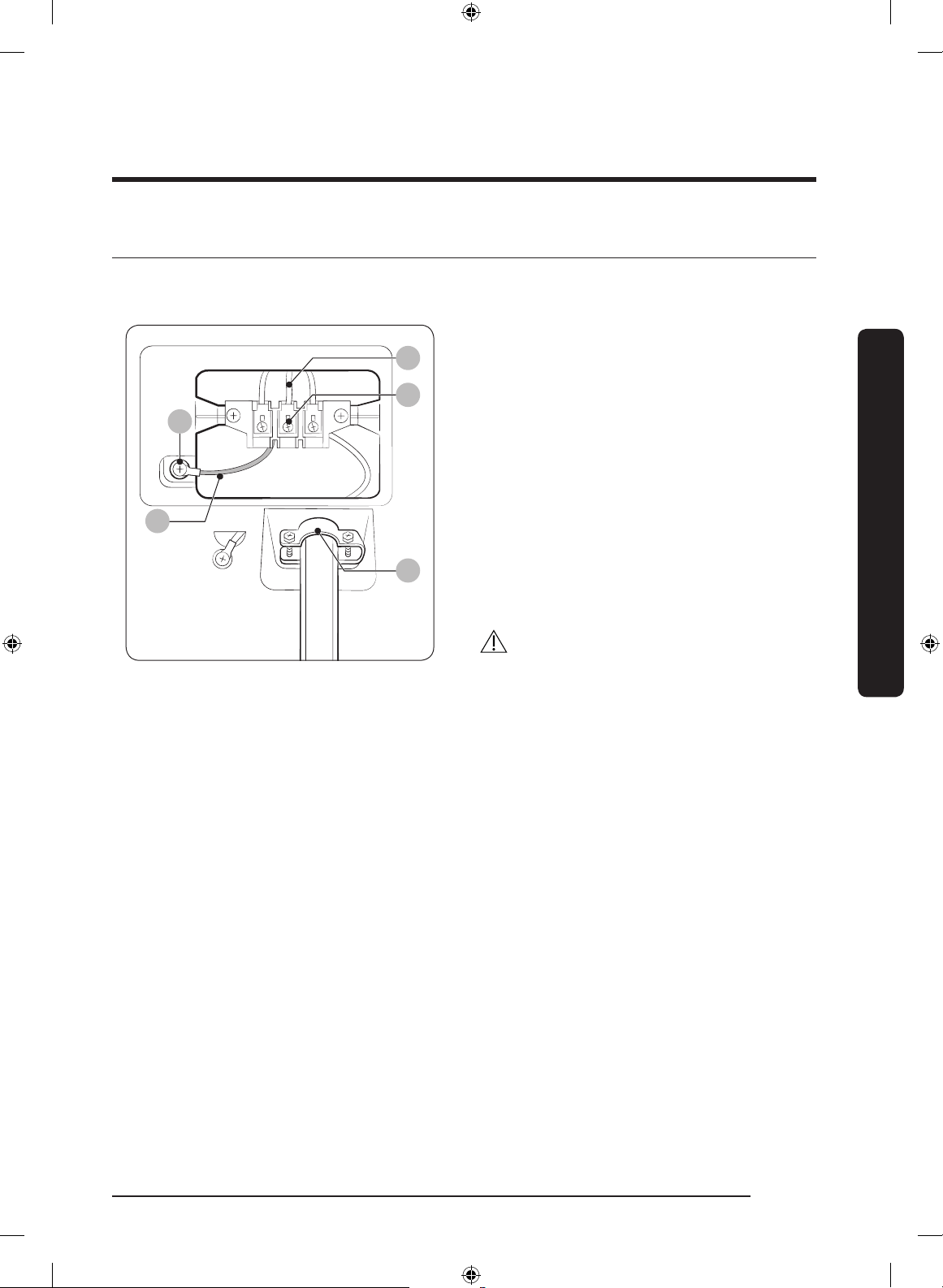
STEP 3 Connect the electrical wiring
First, read through the “Electrical requirements” section, and then follow these steps.
3-wire system
A
B
E
C
D
A. External ground connector
B. Neutral grounding wire (white)
C. Center silver-colored terminal block
screw
D. Neutral wire (white or center wire)
E. ¾” (1.9 cm) UL-listed strain relief
1. Loosen or remove the center terminal
block.
2. Connect the neutral wire (white or
center wire) of the power cable to the
center, silver-colored terminal screw of
the terminal block. Tighten the screws.
3. Connect the other wires to outer
terminal block screws. Tighten the
screws.
4. Tighten the strain relief screws.
5. Insert the terminal block cover into the
rear panel of the dryer. Then, secure the
cover with a hold-down screw.
CAUTION
• To convert from the 4-wire system
to 3-wire system, connect the ground
strap to the terminal block support to
ground the dryer frame to the neutral
conductor.
• Ring-type terminals are recommended.
If using strap terminals, make sure they
are tightened.
DV8700K-03170T-00_EN (US)_151130.indd 19 2015-11-30 12:26:44
Installation
Installation
English20
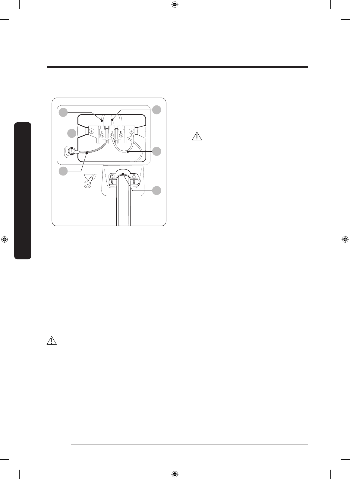
4-wire system
A
B
C
D
F
E
A. External ground connector
B. Green or bare copper wire of power
cord
C. ¾” (1.9 cm) UL-listed strain relief
D. Center silver-colored terminal block
screw
E. Neutral grounding wire (white)
F. Neutral wire (white or center wire)
1. Remove the external ground connector’s
screw, and connect the ground wire
(green or unwrapped) of the power cable
to the screw.
CAUTION
• To connect the ground wire to the
neutral position without through
contact A (cabinet ground), contact
a technician. This is not user
serviceable.
• Ring-type terminals are
recommended. If using strap
terminals, make sure they are
tightened.
2. Loosen or remove the screws from the
center terminal block.
3. Connect the neutral wire (white or
center wire) and ground wire (white) to
the center screw of the terminal block.
Tighten the screw.
4. Connect the other wires to the outer
terminal block screws. Tighten the
screws.
5. Tighten the strain relief screws.
6. Insert the tab of the terminal block cover
into the rear slot of the dryer. Secure the
cover with a hold-down screw.
WARNING
• All U.S. models are designed for a 3-wire system connection. The dryer frame is
grounded to the neutral conductor at the terminal block. A 4-wire system connection
is required for new or remodeled construction, mobile homes, or if local codes do not
permit grounding through neutral. If you use the 4-wire system, you cannot ground the
dryer frame to the neutral conductor at the terminal block.
• Remove the terminal block cover plate. Insert the power cord with a UL-listed strain
relief through the hole provided in the cabinet near the terminal block.
• A strain relief must be used. Do not loosen the nuts already installed on the terminal
block. Be sure they are tight. Use a 3/8” (1 cm) deep well socket.
DV8700K-03170T-00_EN (US)_151130.indd 20 2015-11-30 12:26:44
Installation
English 21
STEP 4 Connect the water hose (applicable models only)
The dryer must be connected to a cold water tap using the provided water hoses.
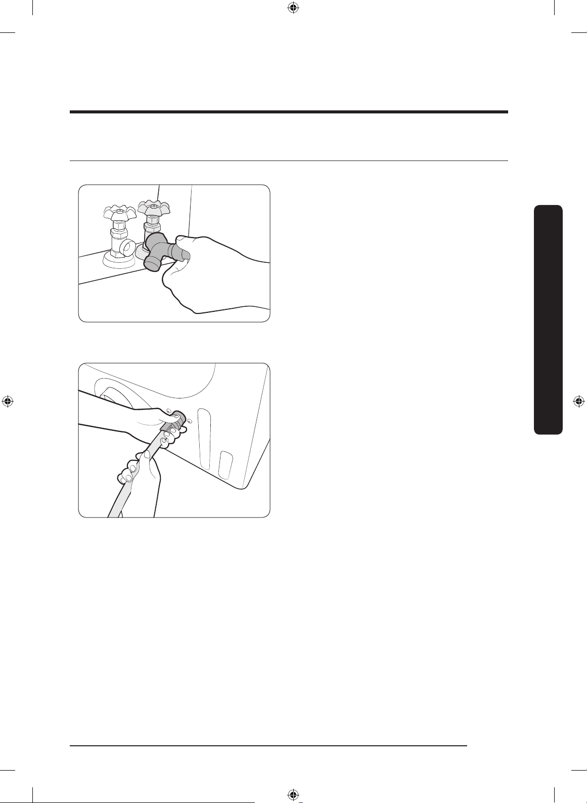
1. Close the cold water tap. If you have a
washer cold water hose attached to the
cold water faucet, unscrew and remove
the hose. Then, connect the female end
of the Y connector to the cold water
tap.
2. Connect the straight end of the water
hose to the Y connector.
3. Using pliers, tighten the coupling an
additional two-thirds turn. Do not
overtighten because the coupling may
be damaged.
4. Connect the angled end of the water
hose to the lling valve at the bottom
of the rear frame. Turn the coupling
manually until it is tight.
5. Using pliers, tighten the coupling an
additional two-thirds turn. Do not
overtighten because the coupling may
be damaged.
6. If you detached the cold water hose
from your washer, attach the hose
to the open end of the Y connector,
tighten the coupling until it is tight,
and then, using a pliers, tighten an
additional two-thirds turn.
7. Open the cold water tap, and then check
for any leaks.
If the Y connector cannot be directly connected to the cold water tap, use the short hose
as shown on the following page.
DV8700K-03170T-00_EN (US)_151130.indd 21 2015-11-30 12:26:44
Installation
Installation
English22
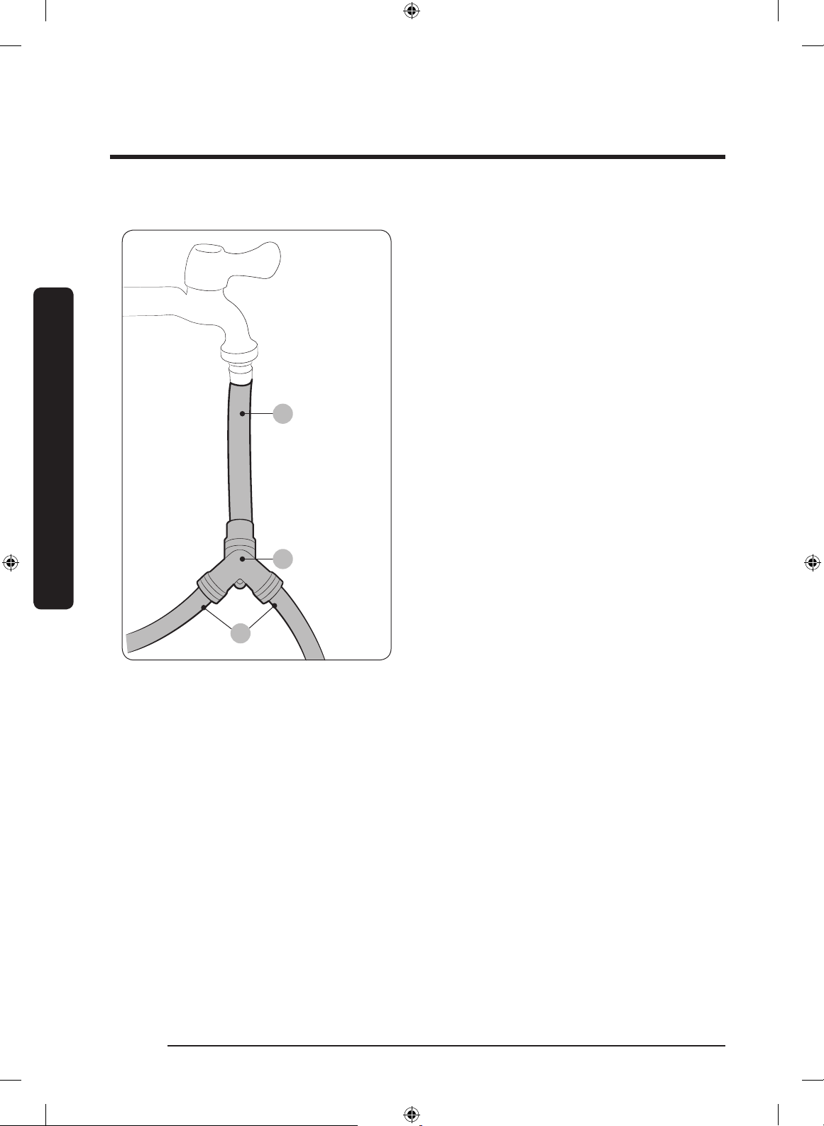
Using the short hose as an extension
B
A
C
1. Close the cold water tap. If you have
a washer cold water hose attached to
the cold water faucet, unscrew and
remove the hose. Then, connect the
short hose (B) to the cold water tap.
Turn the coupling manually until it is
tight.
2. Using pliers, tighten the coupling an
additional two-thirds turn. Do not
overtighten because the coupling may
be damaged.
3. Connect the Y connector (A) to the brass
male end of the short hose. Turn the
coupling manually until it is tight.
4. Using pliers, tighten the coupling an
additional two-thirds turn. Do not
overtighten because the coupling may
be damaged.
5. Connect the angled end of the water
hoses (C) to the lling valve at the
bottom of the rear frame. Turn the
coupling manually until it is tight.
6. Using pliers, tighten the coupling an
additional two-thirds turn. Do not
overtighten because the coupling may
be damaged.
7. If you detached the cold water hose
from your washer, attach the hose to
the free end of the Y connector, tighten
the coupling until it is tight, and then,
using a pliers, tighten an additional
two-thirds turn.
8. Open the cold water tap, and then check
for any leaks.
DV8700K-03170T-00_EN (US)_151130.indd 22 2015-11-30 12:26:44
Installation
English 23
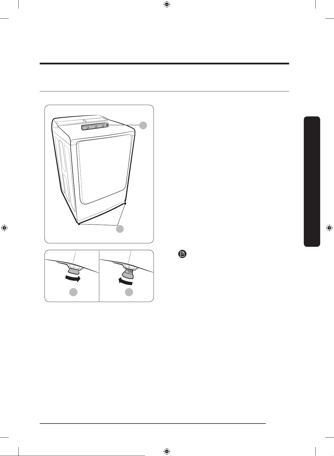
STEP 5 Level the dryer
To ensure optimal performance, the dryer must be level.
A
B
1. Using a level (A), check if the dryer
is level side to side and then front to
back. If the dryer is not level, adjust the
leveling feet (B) at the bottom of the
dryer. Then, check if the dryer is level
again.
A B
NOTE
• To set the dryer to the same height
as your washer, fully retract (A)
the leveling feet by turning them
counterclockwise, then loosen (B) the
feet by turning them clockwise. Once
the dryer is the same height as the
washer, follow the directions above
to level the dryer.
• Adjust the leveling feet only as much
as necessary to level the dryer.
Extending the leveling feet more
than necessary can cause the dryer
to vibrate.
DV8700K-03170T-00_EN (US)_151130.indd 23 2015-11-30 12:26:45
Installation
Installation
English24
STEP 6 Power on (Gas models)
Make sure all gas connections, the exhaust line, and all wiring is connected correctly. Then,
plug the power cord into a power source and check the dryer’s installation and operation
using the nal checklist in Step 7 below.
STEP 7 Final Check
When installation is complete, conrm that:
• The dryer is plugged into an electrical outlet and grounded properly.
• The exhaust ductwork is connected and the joints are taped.
• You have used rigid or stiff-walled exible metal duct material, not plastic exible duct.
• The dryer is level and is sitting rmly on the oor.
• The dryer starts, runs, heats, and shuts off properly.
For gas models:
• The gas is supplied properly with no leaks.
CAUTION
The burner may not ignite initially due to air in the gas line. Allowing your dryer to
operate on a heat setting will purge the line. If the gas does not ignite within 5 minutes,
turn your dryer off and wait 5 minutes. Be sure the gas supply to your dryer has been
turned on. To conrm gas ignition, check the exhaust for heat.
Vent blockage test
After the dryer is installed, start the Vent Blockage Test to check if the duct system is
properly installed. The Vent Blockage Test automatically detects the status of duct and
reports any blockage or problems to the user. Proper ducting can reduce drying time and
save energy.
NOTE
The Vent Blockage Test must run at cool state. If the dryer warms up after the installation
check, run the Air Fluff cycle for several minutes to reduce its internal temperature.
Operation method
1. Make sure the drum is empty and close the door.
(If there are any clothes or other items in the drum, a correct test can not be made.)
2. Press the POWER button to turn the dryer on, then simultaneously press and hold the
Air Fluff and Wrinkle Prevent buttons for 3 seconds.
When entering the Vent Blockage Test, “InS” appears in the display.
(If other procedures are started before entering the Vent Blockage Test, the dryer does
not enter the Vent Blockage Test.)
DV8700K-03170T-00_EN (US)_151130.indd 24 2015-11-30 12:26:45

Installation
English 25
3. The Vent Blockage Test starts immediately after pressing the START button.
During the test, the number indicator makes a circle in 6 steps clockwise.
The test takes about 2 minutes. Do not open the door during the test.
4. After 2 minutes, if the test has completed, the result is displayed and a tone is given.
If status of the duct system is normal, “0” appears and a completion sound is given.
If the duct system can not exhaust properly, “CLg” appears and an alarm sound is given.
In case of any other problem, an information code appears. Check the information
codes in this manual.
• To stop or cancel the Vent Blockage Test, press the POWER button to turn off your
dryer.
• During the test, if “dc” appears, make sure the door is closed. If “C1” is displayed,
make sure the drum has laundry inside.
• The result displays for about 5 minutes and then automatically turns off. You may
turn the result directly off by pressing the POWER button.
NOTE
• During or after the test, the internal drum is hot. Use caution to prevent burns.
The Vent Blockage Test is used to check for problems to the current duct system when
the dryer is installed for the rst time.
• If the test result displays “CLg” (the duct system is blocked ), refer to “Ducting
requirements” and “Exhaust ducting guide” section of this manual and take proper
measures for drying.
If the test is suspended, it could result in incorrect results. Follow the proper
procedures when testing the dryer.
• Even if the test result is normal (“0”), the duct system could be blocked slightly.
Properly install all duct work according to the installation instructions of this manual.
Exhaust ducting guide
Ducting
1. Make sure the dryer is installed properly so the air exhausts freely.
2. Use 4-inch rigid metal ducts. Tape all joints including the dryer connection.
Never use lint-trapping screws.
3. To facilitate the exhaust, keep the ducts as straight as possible.
Cleaning
Clean all old ducts before installing the dryer, and make sure the vent ap opens and
closes freely. We recommend that you to clean the exhaust system annually or on a
regular basis.
DV8700K-03170T-00_EN (US)_151130.indd 25 2015-11-30 12:26:45
Installation
Installation
English26
WARNING
• To prevent re, do not use plastic, thin-foil, or non-metal exible ducts of any kind.
• Do not use a poor exhaust system because it slows down the dryer’s performance.
• Do not use excessively long ducts that have multiple elbows.
• Do not use crushed or clogged venting or ducts.
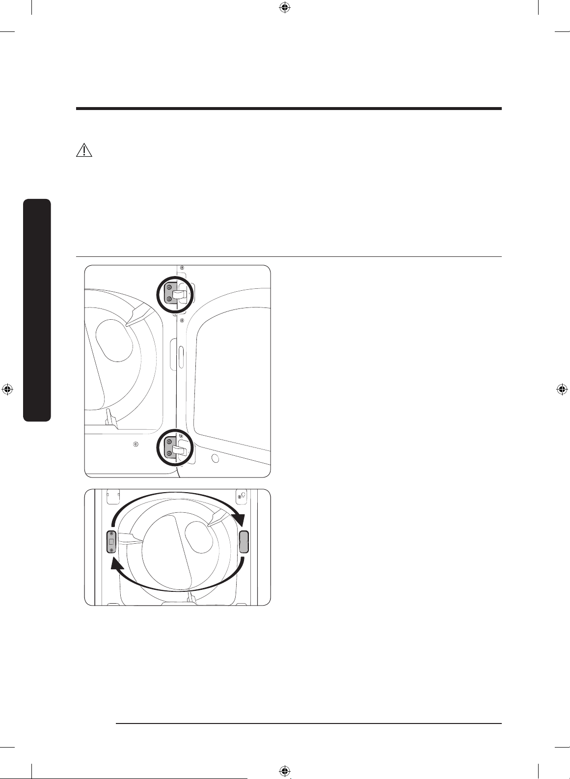
Switching the door position
To reverse the direction of the door, we
recommend that you contact a qualied
technician.
It is recommended to put a soft rug on the
oor to prevent scratches on the door.
1. Unplug the power cord of the dryer.
2. Remove the four hinge screws from
the door, and then remove the door by
lifting it up slightly.
3. Remove the two screws from the lever
holder, and then remove the holder
cover.
4. Put the lever holder on the other side
as shown, and then tighten the screws.
Install the holder cover on the opposite
side as shown.
DV8700K-03170T-00_EN (US)_151130.indd 26 2015-11-30 12:26:45
Installation
English 27
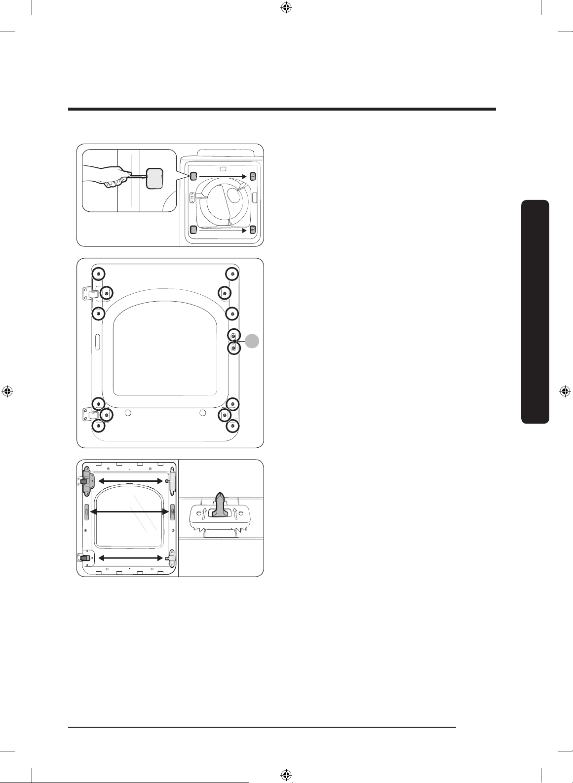
5. Use a at-head screwdriver to remove
the two hinge covers from the original
side. Install the hinge covers on the
opposite side as shown.
B
6. Locate and remove the 14 screws as
shown. Note that screw B (x2) is longer
than the others.
7. Remove the glass holder, and switch
the positions of:
a. the hinge cover and the door handle.
b. the hinge holder and the glass-guide
holder
8. Remove the door lever, and then move
it to the other side as shown.
DV8700K-03170T-00_EN (US)_151130.indd 27 2015-11-30 12:26:45
Installation
Installation
English28
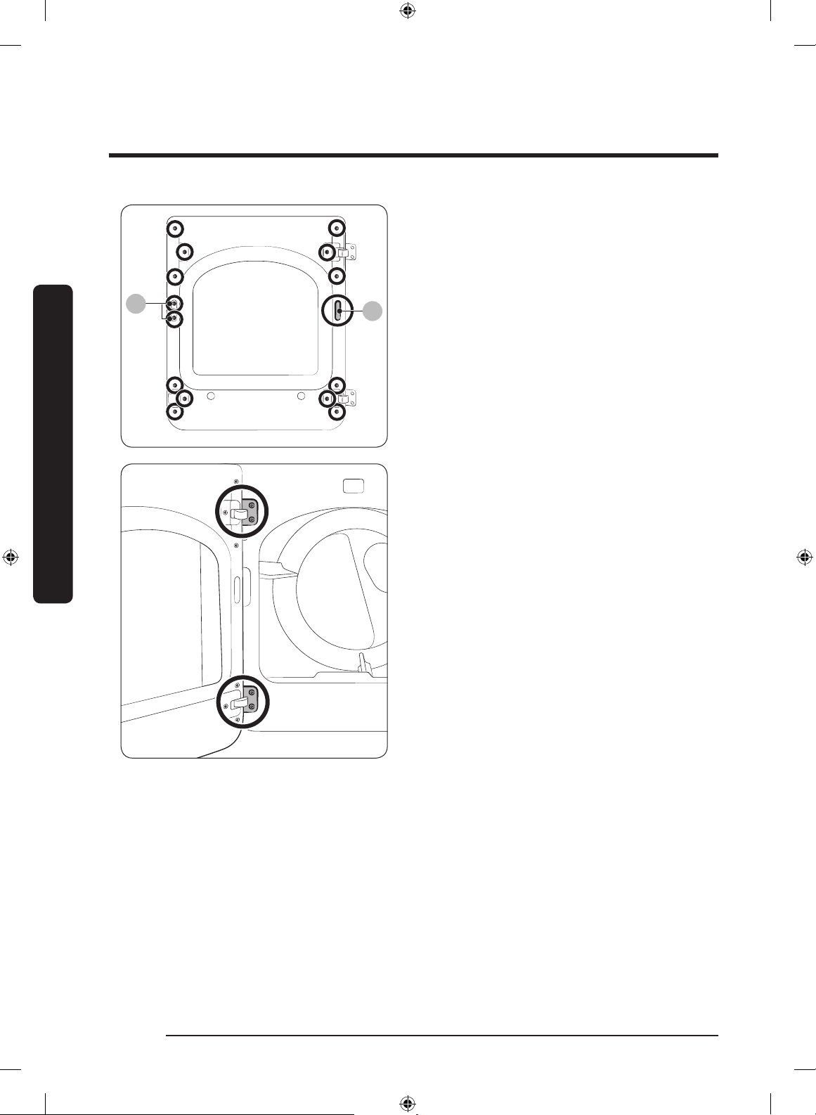
B
C
9. Remove the hole cover (C), and then
insert and tighten the glass holder using
the removed 14 screws.
10. Install the hole cover on the opposite
side as shown.
11. Reinstall the door on the front frame,
and then carefully insert and tighten
the 4 hinge screws.
DV8700K-03170T-00_EN (US)_151130.indd 28 2015-11-30 12:26:46
Before you start
English 29
Before you start
Here are a few things you should know before starting your dryer.
Sort and load
• Put one wash load in the dryer at a
time.
• Do not mix heavy and lightweight items
together.
• To improve drying efciency for one or
two items, add a dry towel to the load.
• For best results, untangle items before
inserting them into the dryer.
• Overloading reduces the tumbling
action, resulting in uneven drying and
wrinkling.
• Unless recommended on the care label,
do not dry woolens or berglass items.
• Avoid drying unwashed items.
• Do not dry items soiled with oil, alcohol,
gasoline, etc.
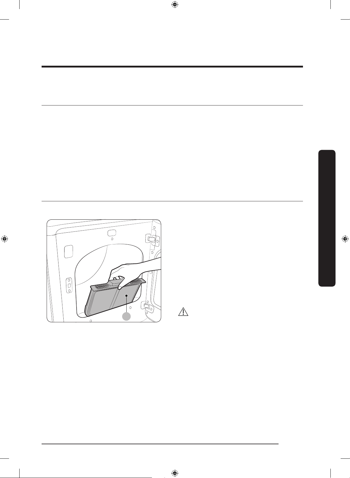
Functional prerequisite
Lint lter
A
To prevent a risk of re, make sure to
clean the lint lter before or after every
load.
1. Turn off the dryer.
2. Open the door, and pull out the lint
lter (A) from inside the tumbler.
3. Remove the lint that has accumulated,
and then clean the lint lter.
4. Reinsert the lint lter, and then close
the door.
CAUTION
• Do not operate the dryer without the
lint lter in place.
• Do not use a damaged or broken lint
lter. This may reduce performance
and/or cause re.
DV8700K-03170T-00_EN (US)_151130.indd 29 2015-11-30 12:26:46
Operations
English30
Operations
WARNING
To reduce the risk of re, electric shock, or injury to persons, read the “Safety information“
before operating this appliance.
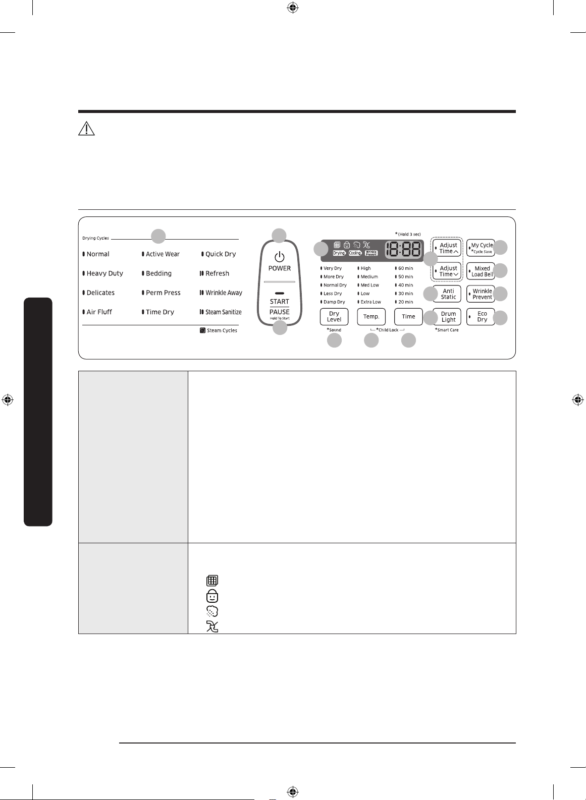
Feature panel
01
03 04 05
13
14
02
07
08
09
10
11
12
06
01 Cycle Selector
Press to select a desired cycle in the left-most panel. When a
cycle is selected, the cycle indicator lights up.
• Sensor Dry cycles: The dryer senses the internal humidity
that will be applied to the drying time. This category includes:
Normal, Heavy Duty, Delicates, Active Wear, Bedding, and
Perm Press.
• Manual Dry cycles: The drying time is xed. This category
includes: Air Fluff, Time Dry, and Quick Dry.
• Steam cycles: The dryer sprays water into the drum to
deodorize clothes and reduce static electricity and wrinkles.
This category includes Refresh, Wrinkle Away, and Steam
Sanitize.
02 Digital Graphic
Display
Displays all cycle information, including the cycle time,
information code, and operating status.
•
Filter Check
•
Child Lock
• Steam
• Vent Sensor
DV8700K-03170T-00_EN (US)_151130.indd 30 2015-11-30 12:26:46
Loading...