

Page 1
Installation Instructions
Compact High-density Analog Current Input Module
Catalog Number 1769-IF16C
Topic Page
Important User Information 2
Electrostatic Discharge 3
Remove Power 3
Hazardous Location 4
Environnements dangereux 4
About the 1769-IF16C Module 5
Install the 1769-IF16C Module 6
Adding the Module to the 1769 System 6
Mounting Expansion I/O 9
Making Field Wiring Connections 11
Configure the 1769-IF16C Module 15
Specifications 23
Replacement Parts 25
Additional Resources 26
Page 2
2 Compact High-density Analog Current Input Module
Important User Information
Solid state equipment has operational characteristics differing from those of electromechanical equipment.
Safety Guidelines for the Application, Installation and Maintenance of Solid State Controls (Publication
available from your local Rockwell Automation sales office or online at
SGI-1.1
http://literature.rockwellautomation.com
equipment and hard-wired electromechanical devices. Because of this difference, and also because of the
wide variety of uses for solid state equipment, all persons responsible for applying this equipment must
satisfy themselves that each intended application of this equipment is acceptable.
In no event will Rockwell Automation, Inc. be responsible or liable for indirect or consequential damages
resulting from the use or application of this equipment.
The examples and diagrams in this manual are included solely for illustrative purposes. Because of the many
variables and requirements associated with any particular installation, Rockwell Automation, Inc. cannot
assume responsibility or liability for actual use based on the examples and diagrams.
No patent liability is assumed by Rockwell Automation, Inc. with respect to use of information, circuits,
equipment, or software described in this manual.
Reproduction of the contents of this manual, in whole or in part, without written permission of Rockwell
Automation, Inc., is prohibited.
Throughout this manual, when necessary, we use notes to make you aware of safety considerations.
WARNING
Identifies information about practices or circumstances that can cause an explosion in
a hazardous environment, which may lead to personal injury or death, property
damage, or economic loss.
) describes some important differences between solid state
IMPORTANT
ATTENTION
SHOCK HAZARD
BURN HAZARD
Identifies information that is critical for successful application and understanding of
the product.
Identifies information about practices or circumstances that can lead to personal injury
or death, property damage, or economic loss. Attentions help you identify a hazard,
avoid a hazard and recognize the consequences.
Labels may be on or inside the equipment (for example, a drive or motor) to alert
people that dangerous voltage may be present.
Labels may be on or inside the equipment (for example, a drive or motor) to alert
people that surfaces may reach dangerous temperatures.
Publication 1769-IN085A-EN-P - August 2008
Page 3
Electrostatic Discharge
Compact High-density Analog Current Input Module 3
ATTENTION
Electrostatic discharge can damage integrated circuits or
semiconductors if you touch bus connector pins. Follow these
guidelines when you handle the module:
Remove Power
ATTENTION
Remove power before removing or inserting this module. When you
remove or insert a module with power applied, an electrical arc may
occur. An electrical arc can cause personal injury or property damage
by:
Electrical arcing causes excessive wear to contacts on both the module
and its mating connector. Worn contacts may create electrical
resistance.
• Touch a grounded object to discharge static potential.
• Wear an approved wrist-strap grounding device.
• Do not touch the bus connector or connector pins.
• Do not touch circuit components inside the module.
• Use a static-safe work station, if available.
• Keep the module in its static-shield box when not in use.
• sending an erroneous signal to your system’s field devices, causing
unintended machine motion.
• causing an explosion in a hazardous environment.
Publication 1769-IN085A-EN-P - August 2008
Page 4
4 Compact High-density Analog Current Input Module
Hazardous Location
This equipment is suitable for use in Class I, Division 2, Groups A, B, C, D or
non-hazardous locations only. The following statement applies to use in hazardous
locations.
WARNING
EXPLOSION HAZARD
Substitution of components may impair suitability for Class I, Division 2.
Do not replace components or disconnect equipment unless power is
switched off or the area is known to be non-hazardous.
Do not connect or disconnect components unless power is switched off
or the area is known to be non-hazardous.
This product must be installed in an enclosure.
All wiring must comply with Class I, Division 2 wiring methods of Article
501 of the National Electrical Code and/or in accordance with Section
18-1J2 of the Canadian Electrical Code, and in accordance with the
authority having jurisdiction.
Environnements dangereux
Cet équipement est conçu pour être utilisé dans des environnements de Classe 1,
Division 2, Groupes A, B, C, D ou non dangereux. La mise en garde suivante
s’applique à une utilisation dans des environnements dangereux.
ATTENTION
DANGER D’EXPLOSION
La substitution de composants peut rendre cet équipement impropre
à une utilisation en environnement de Classe 1, Division 2.
Ne pas remplacer de composants ou déconnecter l'équipement sans
s'être assuré que l'alimentation est coupée et que l'environnement
est classé non dangereux.
Ne pas connecter ou déconnecter des composants sans s'être assuré
que l'alimentation est coupée ou que l'environnement est classé non
dangereux.
Ce produit doit être installé dans une armoire.
Publication 1769-IN085A-EN-P - August 2008
Page 5
Compact High-density Analog Current Input Module 5
About the 1769-IF16C Module
Compact I/O is suitable for use in an industrial environment when installed in
accordance with these instructions. Specifically, this equipment is intended for use
in clean, dry environments (Pollution degree 2
Over Voltage Category II
(2)
(IEC 60664-1)
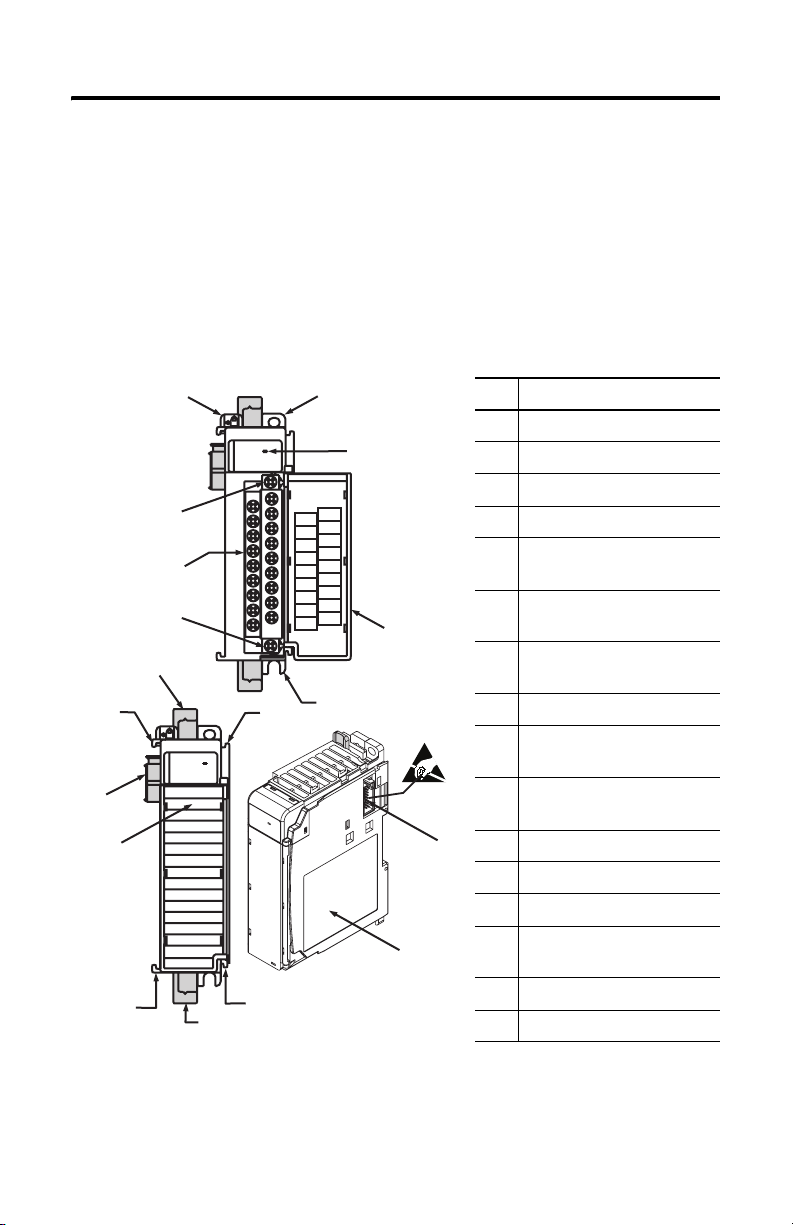
Module Description
(1)
) and to circuits not exceeding
(3)
.
5a
7a
9
12a
OK
Analog
DANGER
Do Not Remove RTB Under Power
Unless Area is Non-Hazardous
10a
10
10b
IN0+
IN1+
IN2+
IN3+
IN4+
IN5+
IN6+
IN7+
COM
COM
IN8+
IN9+
IN10+
IN11+
IN12+
IN13+
IN14+
IN15+
Ensure Adjacent
Bus Lever is Unlatched/Latched
Before/After
Removing/Inserting Module
1769-IF16C
8a
2b
7b
7a
OK
Analog
7b
8b
Item Description
1 Bus lever (with locking function)
3
2a Upper panel mounting tab
2b Lower panel mounting tab
3 Module status indicator
4 Module door with terminal
identification label
5a Movable bus connector
4
with female pins
5b Stationary bus connector
with male pins
6 Nameplate label
7a Upper
tongue-and-groove slots
7b Lower
tongue-and-groove slots
5b
8a Upper DIN rail latch
8b Lower DIN rail latch
9 Write-on label (user ID tag)
6
10 Removable terminal block (RTB)
with finger-safe cover
10a RTB upper retaining screw
10b RTB lower retaining screw
(1) Pollution Degree 2 is an environment where, normally, only non-conductive pollution occurs except that occasionally a
temporary conductivity caused by condensation is expected.
(2) Over Voltage Category II is the load level section of the electrical distribution system. At this level, transient voltages are
controlled and do not exceed the impulse voltage capability of the product’s insulation.
(3) Pollution Degree 2 and Over Voltage Category II are International Electrotechnical Commission (IEC) designations.
Publication 1769-IN085A-EN-P - August 2008
Page 6
6 Compact High-density Analog Current Input Module
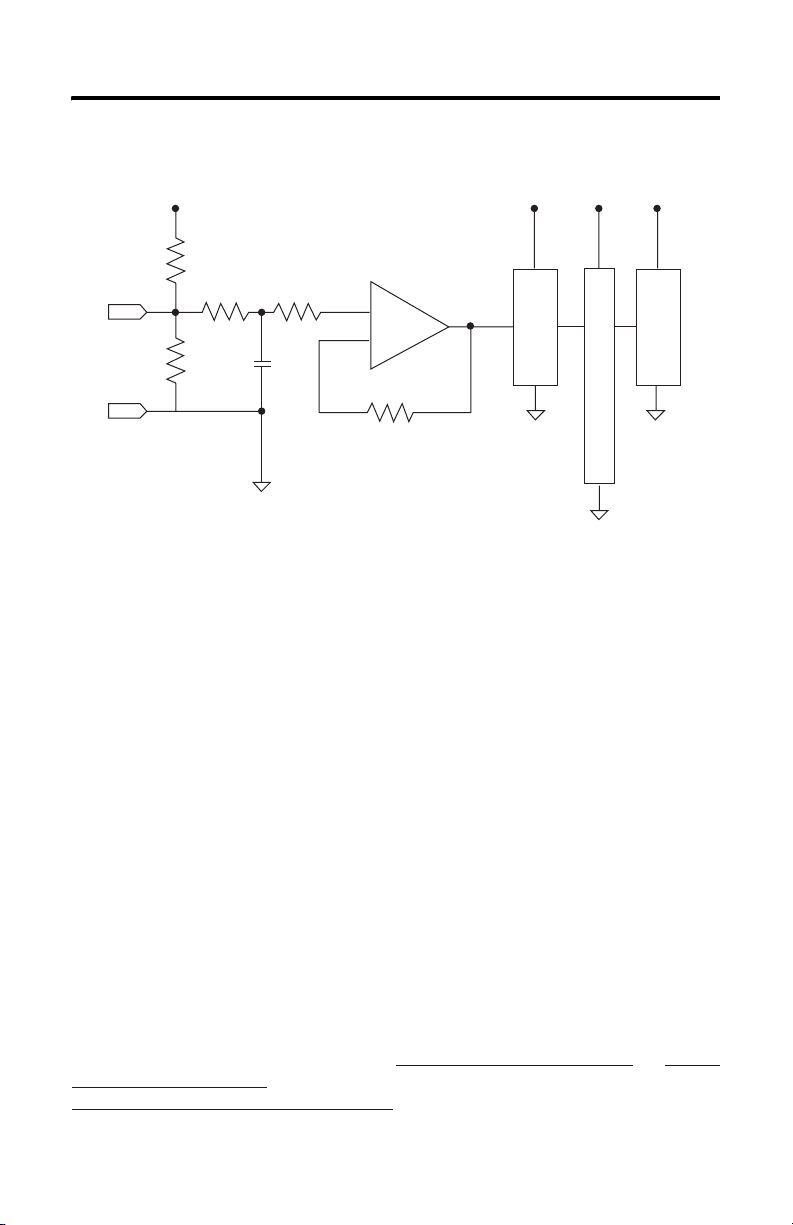
Simplified Input Circuit Diagram
V
LOCAL
10 M
IN+
200
249
COM
20 K
+
-
0.1 μF
20 K
Install the 1769-IF16C Module
Follow these steps to install the module.
V
LOCALVLOCALVLOCAL
M
u
Gain A/D
l
t
i
p
l
e
x
e
r
1. Add the module to the 1769 system.
You can add the module before or after mounting.
2. Mount Expansion I/O.
• Panel mount
• DIN-rail mount
3. Make field wiring connections.
4. Configure the module.
This publication describes these steps in detail.
Adding the Module to the 1769 System
Attach the module to the controller or an adjacent I/O module before or after
mounting. For mounting instructions, see Use the Dimensional Template
the Module to a DIN Rail. To work with a system that is already mounted, see
Replace a Single Module Within a System
.
Publication 1769-IN085A-EN-P - August 2008
, or Mount
Page 7
Compact High-density Analog Current Input Module 7
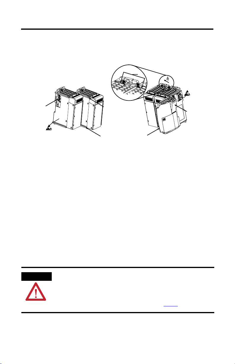
Assemble the 1769 System
The following procedure shows you how to assemble the Compact I/O system.
3
4
2
1. Disconnect power.
2. Check that the bus lever of the module to be installed is in the unlocked
(fully right) position.
3. Use the upper and lower tongue-and-groove slots (1) to secure the modules
together or to a controller.
4. Move the module back along the tongue-and-groove slots until the bus
connectors (2) line up with each other.
5. Push the bus lever back slightly to clear the positioning tab (3).
Use your fingers or a small screwdriver.
6. To allow communication between the controller and module, move the bus
lever fully to the left (4) until it clicks, making sure it is locked firmly in
place.
ATTENTION
When attaching I/O modules, it is very important that the bus connectors
1
1
5
are securely locked together to be sure of proper electrical connection.
Securely locking together the bus connectors is required for use in
hazardous locations.
For more information on hazardous locations see page 4
.
7. Attach an end-cap terminator (5) to the last module in the system by using
the tongue-and-groove slots as before.
Publication 1769-IN085A-EN-P - August 2008
Page 8

8 Compact High-density Analog Current Input Module
8. Lock the end-cap bus terminator (6).
IMPORTANT
You must use a 1769-ECR or 1769-ECL right or left end cap to terminate
the end of the serial communication bus. An I/O configuration fault will
occur if an end cap is not used.
Replace a Single Module Within a System
The module can be replaced while the system is mounted to a panel or DIN rail.
1. Remove power.
See Remove Power
2. Remove the upper and lower mounting screws from the module or open the
DIN latches using a flat-blade or Phillips screwdriver.
3. Move the bus lever to the right to disconnect or unlock the bus.
4. On the right-side adjacent module, move its bus lever to the right (unlock)
to disconnect it from the module to be removed.
5. Gently slide the disconnected module forward.
If you feel excessive resistance, check that the module is disconnected from
the bus and that both mounting screws are removed or DIN latches opened.
TIP
on page 3.
It may be necessary to rock the module slightly from front to back
to remove it, or, in a panel-mounted system, to loosen the screws
of adjacent modules.
6. Be sure that the bus lever on the module and on the right-side adjacent
module are in the unlocked (fully right) position before installing the
replacement module.
7. Slide the replacement module into the open slot.
8. Connect the modules by locking (fully left) the bus levers on the
replacement module and the right-side adjacent module.
9. Replace the mounting screws or snap the module onto the DIN rail.
Publication 1769-IN085A-EN-P - August 2008
Page 9
Mounting Expansion I/O
Compact High-density Analog Current Input Module 9
ATTENTION
During panel or DIN rail mounting of all devices, be sure that all debris,
that is, metal chips or wire strands, is kept from falling into the module.
Debris that falls into the module could cause damage when cycling
power.
Minimum Spacing
Maintain spacing from enclosure walls, wireways, or adjacent equipment. Allow
50 mm (2 in.) of space on all sides for adequate ventilation, as shown.
To p
Side Side
Controller
Compact I/O
Bottom
Compact I/O
Compact I/O
End Cap
Compact I/O
Compact I/O
Mount the Module to a Panel
Mount the module to a panel using two screws per module. Use M4 or #8 panhead
screws. Mounting screws are required on every module.
Publication 1769-IN085A-EN-P - August 2008
Page 10

10 Compact High-density Analog Current Input Module
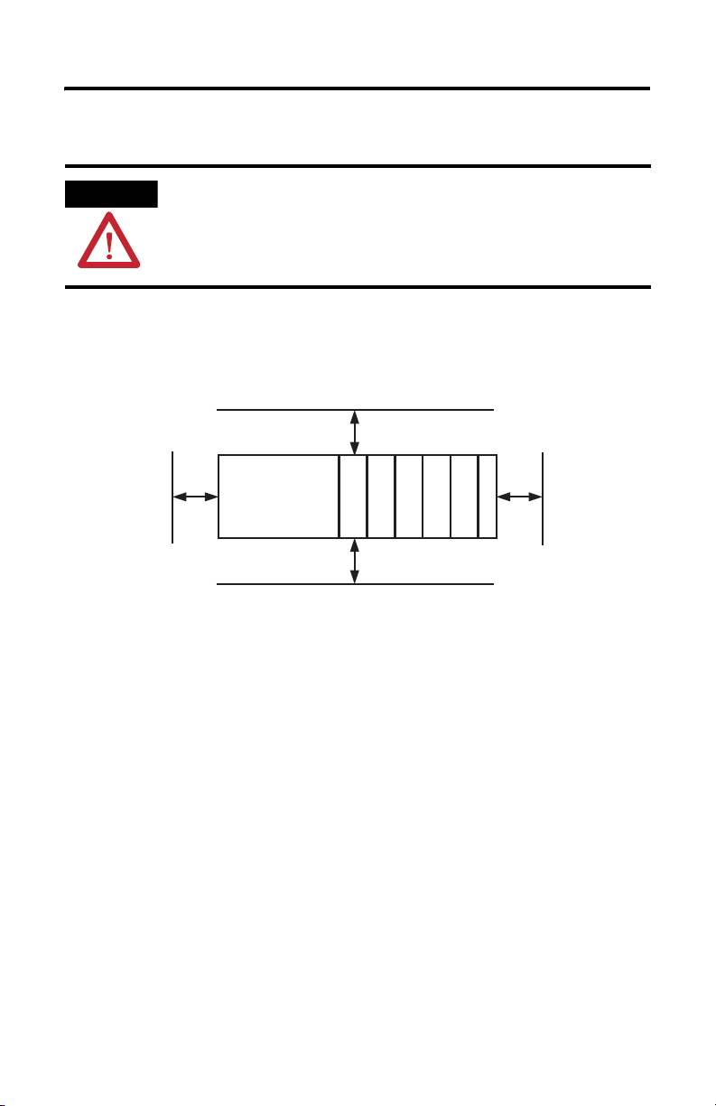
Use the Dimensional Template
Spacing for single-wide modules 35 mm (1.378 in.)
Spacing for one-and-a-half wide modules 52.5 mm (2.067 in.)
Refer to host controller documentation for this dimension.
NOTE: Overall spacing
tolerance ±0.44 mm (0.016 in.)
Locate holes every 17.5 mm (0.689 in.) to allow for a mix of single-wide and
one-and-a-half-wide modules (for example, the 1769-OA16 module).
Use Modules as a Template
This procedure lets you use the assembled modules as a template for drilling holes
in the panel. See Use the Dimensional Template
mounting equipment.
if you have sophisticated panel
On a clean work surface, assemble no more than three modules.
Due to module-mounting hole tolerance, it is important to follow this procedure.
1. Using the assembled modules as a template, carefully mark the center of all
module-mounting holes on the panel.
2. Return the assembled modules to the clean work surface, including any
previously mounted modules.
3. Drill and tap the mounting holes for the recommended M4 or #8 screws.
4. Place the modules back on the panel, and check for proper hole alignment.
5. Attach the modules to the panel using the mounting screws.
TIP
If you are mounting more modules, mount only the last one of this
group and put the others aside. This reduces the remounting time
during drilling and tapping of the next group.
6. Repeat steps 1…6 for any remaining modules.
Publication 1769-IN085A-EN-P - August 2008
Page 11

Compact High-density Analog Current Input Module 11
Mount the Module to a DIN Rail
The module can be mounted using these DIN rails:
• 35 x 7.5 mm (EN 50 022 - 35 x 7.5)
• 35 x 15 mm (EN 50 022 - 35 x 15)
To mount the module on a DIN rail, follow these steps.
1. Close the DIN rail latches.
2. Press the DIN rail mounting area of the module against the DIN rail.
The latches will momentarily open and lock into place.
Making Field Wiring Connections
Use the information in this section to wire the module.
• Grounding the module
• System wiring guidelines
• Input sensors/transmitters wiring
• Terminal labels
• Finger-safe terminal block wiring and removal
• Wire size and terminal screw torque
Grounding the Module
This product is intended to be mounted to a well-grounded mounting surface such
as a metal panel. Additional grounding connections from the module’s mounting
tabs or DIN rail, if used, are not required unless the mounting surface cannot be
grounded. Refer to Industrial Automation Wiring and Grounding Guidelines,
publication 1770-4.1
, for additional information.
Publication 1769-IN085A-EN-P - August 2008
Page 12

12 Compact High-density Analog Current Input Module
System Wiring Guidelines
Consider the following when wiring your system:
• All module commons (COM) are connected in the analog module.
• The analog common (COM) is not connected to earth ground inside the
module.
• Channels are not isolated from each other.
• Use Belden 8761, or equivalent, shielded wire.
• Under normal conditions, the drain wire and shield junction must be
connected to earth ground via a panel or DIN rail mounting screw at the
analog I/O module end. Keep the shield connection to ground as short as
possible.
• To ensure optimum accuracy, limit overall cable impedance by keeping your
cable as short as possible. Locate the I/O system as close to your sensors or
actuators as your application will permit.
• If multiple power supplies are used with analog inputs, the power supply
commons must be connected.
• The 1769-IF16C module does not provide loop power for analog inputs. Use
a Class 2-rated power supply that matches the input transmitter
specifications.
• Voltages on the IN+ terminals of the 1769-IF16C module must be within
+/-10V DC of analog common.
(1)
(2)
ATTENTION
Be careful when stripping wires. Wire fragments that fall into a
module could cause damage at power up. Once wiring is complete,
ensure the module is free of all metal fragments.
(1) In environments where high-frequency noise may be present, it may be necessary to directly ground cable shields to earth
at the module end and via a 0.1 µF capacitor at the sensor end.
(2) Cable length over 50 m (164 ft) may impact accuracy. For details, refer to the Compact High-Density Analog Input Modules
User Manual, publication 1769-UM018.
Publication 1769-IN085A-EN-P - August 2008
Page 13

Compact High-density Analog Current Input Module 13
Wire Input Sensors/Transmitters
Sensor/
Tra ns mi tte r
Supply
Power
+
-
(1)
Current
Tra ns mi tte r
+
Signal
Current Transmitter
Ground
+
(1) The sensor power supply must be rated Class 2.
Signal
1769-IF16C Terminal Block
IN0+
IN1+
IN2+
IN3+
IN4+
IN5+
IN6+
IN7+
Com
Com
IN8+
IN9+
IN10+
IN11+
IN12+
IN13+
IN14+
IN15+
Label the Terminals
A removable, write-on label is provided with the module. Remove the label from
the door, mark the identification of each terminal with permanent ink, and slide the
label back into the door. Your markings (ID tag) will be visible when the module
door is closed.
Remove the Finger-safe Terminal Block
When wiring field devices to the module, it is not necessary to remove the terminal
block. If you remove the terminal block, use the write-on label on the side of the
terminal block to identify the module slot location and type.
R L
SLOT # ____
MODULE TYPE _____
To remove the terminal block, loosen the upper and lower retaining screws. The
terminal block will back away from the module as you remove the screws. When
replacing the terminal block, torque the retaining screws to 0.46 N
RoHS
•m (4.1 in•lbs).
Publication 1769-IN085A-EN-P - August 2008
Page 14

14 Compact High-density Analog Current Input Module
Wire the Finger-safe Terminal Block
Upper Retaining Screw
Lower Retaining Screw
When wiring the terminal block, keep the finger-safe cover in place.
1. Loosen the terminal screws to be wired.
2. Route the wire under the terminal pressure plate.
You can use the bare wire or a spade lug. The terminals will accept a
6.35 mm (0.25 in.) spade lug.
TIP
The terminal screws are non-captive. Therefore, it is possible
to use a ring lug [maximum 1/4 inch o.d. with a 0.139 inch
minimum i.d. (M3.5)] with the module.
3. Tighten the terminal screw making sure the pressure plate secures the wire.
Recommended torque when tightening terminal screws is 0.68 N•m
(6 in•lbs).
TIP
If you need to remove the finger-safe cover, insert a screw
driver into one of the square wiring holes and gently pry the
cover off. If you wire the terminal block with the finger-safe
cover removed, you will not be able to put it back on the
terminal block because the wires will be in the way.
Wire Size and Terminal Screw Torque
Each terminal accepts two wires with the following restrictions:.
Wire Type Wire Size Terminal Screw
Tor qu e
Solid Cu-90 °C (194 °F) #14…#22 AWG 0.68 N•m (6 in•lb) 0.46 N•m (4.1 in•lb)
Stranded Cu-90 °C (194 °F) #16…#22 AWG 0.68 N•m (6 in•lb) 0.46 N•m (4.1 in•lb)
Publication 1769-IN085A-EN-P - August 2008
Retaining Screw
To rq ue
Page 15

Compact High-density Analog Current Input Module 15
Configure the 1769-IF16C Module
Use the following I/O memory mapping tables to configure the 1769-IF16C module.
Output Data File
For each module, slot x, words 0 and 1 in the output data file contain the cancel
latched channel alarm control bits.
Word/
15 14 13 12 11 10 09 08 07 06 05 04 03 02 01 00
Bit
Word 0 CLL7CLH7CLL6CLH6CLL5CLH5CLL4CLH4CLL3CLH3CLL2CLH2CLL1CLH1CLL0CL
Word 1 CL
L15CLH15CLL14CLH14CLL13CLH13CLL12CLH12CLL11CLH11CLL10CLH10CLL9CLH9CLL8CLH8
The bits are defined as follows:
• CLHx = Cancel High Process Alarm Latch for Input x: Allows each input
high-process-alarm latch to be individually cancelled. Cancel = 1.
• CLLx = Cancel Low Process Alarm Latch for Input x: Allows each input
low-process-alarm latch to be individually cancelled. Cancel = 1.
H0
Publication 1769-IN085A-EN-P - August 2008
Page 16

16 Compact High-density Analog Current Input Module
Input Data File
For each module, slot x, words 0…15 in the input data file contain the converted
value of the module’s analog input channels. Word 16 in the input data file contains
the time stamp value (if time stamping is enabled) that corresponds to the module's
last input data sampling period. Words 17…21 in the input data file contain status
bits for the analog input channels.
Input Data Array
Word/
Bit
Word 0 SGN Analog Read (Input) Data Value Channel 0
Word 1 SGN Analog Read (Input) Data Value Channel 1
Word 2 SGN Analog Read (Input) Data Value Channel 2
Word 3 SGN Analog Read (Input) Data Value Channel 3
Word 4 SGN Analog Read (Input) Data Value Channel 4
Word 5 SGN Analog Read (Input) Data Value Channel 5
Word 6 SGN Analog Read (Input) Data Value Channel 6
Word 7 SGN Analog Read (Input) Data Value Channel 7
Word 8 SGN Analog Read (Input) Data Value Channel 8
Word 9 SGN Analog Read (Input) Data Value Channel 9
Word 10 SGN Analog Read (Input) Data Value Channel 10
Word 11 SGN Analog Read (Input) Data Value Channel 11
Word 12 SGN Analog Read (Input) Data Value Channel 12
Word 13 SGN Analog Read (Input) Data Value Channel 13
Word 14 SGN Analog Read (Input) Data Value Channel 14
Word 15 SGN Analog Read (Input) Data Value Channel 15
Word 16 Nu Time Stamp Value
Word 17 S15 S14 S13 S12 S11 S10 S9 S8 S7 S6 S5 S4 S3 S2 S1 S0
Word 18 L3 H3 U3 O3 L2 H2 U2 O2 L1 H1 U1 O1 L0 H0 U0 O0
Word 19 L7 H7 U7 O7 L6 H6 U6 O6 L5 H5 U5 O5 L4 H4 U4 O4
Word 20 L11 H11 U11 O11 L10 H10 U10 O10 L9 H9 U9 O9 L8 H8 U8 O8
Word 21 L15 H15 U15 O15 L14 H14 U14 O14 L13 H13 U13 O13 L12 H12 U12 O12
15 14 13 12 11 10 09 08 07 06 05 04 03 02 01 00
Publication 1769-IN085A-EN-P - August 2008
Page 17

Compact High-density Analog Current Input Module 17
The bits are defined as follows:
• SGN = Sign bit in 2’s complement format.
• Nu = Not Used. Bit set to 0.
• Sx = General Status bit for input channels 0…15.
• Ox = Over range flag bits for input channels 0…15.
• Ux = Under range flag bits for input channels 0…15.
• Hx = High Alarm flag bits for input channels 0…15.
• Lx = Low Alarm flag bits for input channels 0…15.
Configuration Data File
The manipulation of bits from this file is normally done with programming software
(for example, RSLogix 5000, RSLogix 500, or RSNetWorx for DeviceNet software)
during initial configuration of the system. In that case, graphical screens provided
by the programming software simplify configuration.
Some systems, like the 1769-ADN DeviceNet adapter system, also allow the bits to
be altered as part of the control program using communication rungs. In that case,
it is necessary to understand the bit arrangement.
Configuration Data Array
Word/Bit 15 14 13 12 11 10 09 08 07 06 05 04 03 02 01 00
Word 0 0 Real Time Sample Value
Word 1 ETS Reserved
(1)
Word 2 EC Reserved EA AL
Word 3 Reserved Input Data
Format Ch0
Word 4 SGN Process Alarm High Data Value Channel 0
Word 5 SGN Process Alarm Low Data Value Channel 0
Word 6 SGN Alarm Dead Band Value Channel 0
Word 7 Reserved
Word 8 EC Reserved EA AL
Word 9 Reserved Input Data
Format Ch1
Word 10 SGN Process Alarm High Data Value Channel 1
Word 11 SGN Process Alarm Low Data Value Channel 1
Word 12 SGN Alarm Dead Band Value Channel 1
Word 13 Reserved
Reserved Input Filter Sel Ch0
EI
Reserved Input Type/Range
(1)
Reserved Input Filter Sel Ch1
EI
Reserved Input Type/Range
Select Ch0
Select Ch1
Publication 1769-IN085A-EN-P - August 2008
Page 18

18 Compact High-density Analog Current Input Module
Configuration Data Array
Word/Bit 15 14 13 12 11 10 09 08 07 06 05 04 03 02 01 00
Word 14 EC Reserved EA AL
Word 15 Reserved Input Data
Format Ch2
Word 16 SGN Process Alarm High Data Value Channel 2
Word 17 SGN Process Alarm Low Data Value Channel 2
Word 18 SGN Alarm Dead Band Value Channel 2
Word 19 Reserved
Word 20 EC Reserved EA AL
Word 21 Reserved Input Data
Format Ch3
Word 22 SGN Process Alarm High Data Value Channel 3
Word 23 SGN Process Alarm Low Data Value Channel 3
Word 24 SGN Alarm Dead Band Value Channel 3
Word 25 Reserved
Word 26 EC Reserved EA AL
Word 27 Reserved Input Data
Format Ch4
Word 28 SGN Process Alarm High Data Value Channel 4
Word 29 SGN Process Alarm Low Data Value Channel 4
Word 30 SGN Alarm Dead Band Value Channel 4
Word 31 Reserved
Word 32 EC Reserved EA AL
Word 33 Reserved Input Data
Format Ch5
Word 34 SGN Process Alarm High Data Value Channel 5
Word 35 SGN Process Alarm Low Data Value Channel 5
Word 36 SGN Alarm Dead Band Value Channel 5
Word 37 Reserved
(1)
Reserved Input Filter Sel Ch2
EI
Reserved Input Type/Range
Select Ch2
(1)
Reserved Input Filter Sel Ch3
EI
Reserved Input Type/Range
Select Ch3
(1)
Reserved Input Filter Sel Ch4
EI
Reserved Input Type/Range
Select Ch4
(1)
Reserved Input Filter Sel Ch5
EI
Reserved Input Type/Range
Select Ch5
Publication 1769-IN085A-EN-P - August 2008
Page 19

Compact High-density Analog Current Input Module 19
Configuration Data Array
Word/Bit 15 14 13 12 11 10 09 08 07 06 05 04 03 02 01 00
Word 38 EC Reserved EA AL
Word 39 Reserved Input Data
Format Ch6
Word 40 SGN Process Alarm High Data Value Channel 6
Word 41 SGN Process Alarm Low Data Value Channel 6
Word 42 SGN Alarm Dead Band Value Channel 16
Word 43 Reserved
Word 44 EC Reserved EA AL
Word 45 Reserved Input Data
Format Ch7
Word 46 SGN Process Alarm High Data Value Channel 7
Word 47 SGN Process Alarm Low Data Value Channel 7
Word 48 SGN Alarm Dead Band Value Channel 7
Word 49 Reserved
Word 50 EC Reserved EA AL
Word 51 Reserved Input Data
Format Ch8
Word 52 SGN Process Alarm High Data Value Channel 8
Word 53 SGN Process Alarm Low Data Value Channel 8
Word 54 SGN Alarm Dead Band Value Channel 8
Word 55 Reserved
Word 56 EC Reserved EA AL
Word 57 Reserved Input Data
Format Ch9
Word 58 SGN Process Alarm High Data Value Channel 9
Word 59 SGN Process Alarm Low Data Value Channel 9
Word 60 SGN Alarm Dead Band Value Channel 9
Word 61 Reserved
(1)
Reserved Input Filter Sel Ch6
EI
Reserved Input Type/Range
Select Ch6
(1)
Reserved Input Filter Sel Ch7
EI
Reserved Input Type/Range
Select Ch7
(1)
Reserved Input Filter Sel Ch8
EI
Reserved Input Type/Range
Select Ch8
(1)
Reserved Input Filter Sel Ch9
EI
Reserved Input Type/Range
Select Ch9
Publication 1769-IN085A-EN-P - August 2008
Page 20

20 Compact High-density Analog Current Input Module
Configuration Data Array
Word/Bit 15 14 13 12 11 10 09 08 07 06 05 04 03 02 01 00
Word 62 EC Reserved EA AL
Word 63 Reserved Input Data
Format Ch10
Word 64 SGN Process Alarm High Data Value Channel 10
Word 65 SGN Process Alarm Low Data Value Channel 10
Word 66 SGN Alarm Dead Band Value Channel 10
Word 67 Reserved
Word 68 EC Reserved EA AL
Word 69 Reserved Input Data
Format Ch11
Word 70 SGN Process Alarm High Data Value Channel 11
Word 71 SGN Process Alarm Low Data Value Channel 11
Word 72 SGN Alarm Dead Band Value Channel 11
Word 73 Reserved
Word 74 EC Reserved EA AL
Word 75 Reserved Input Data
Format Ch12
Word 76 SGN Process Alarm High Data Value Channel 12
Word 77 SGN Process Alarm Low Data Value Channel 12
Word 78 SGN Alarm Dead Band Value Channel 12
Word 79 Reserved
Word 80 EC Reserved EA AL
Word 81 Reserved Input Data
Format Ch13
Word 82 SGN Process Alarm High Data Value Channel 13
Word 83 SGN Process Alarm Low Data Value Channel 13
Word 84 SGN Alarm Dead Band Value Channel 13
Word 85 Reserved
(1)
Reserved Input Filter Sel Ch10
EI
Reserved Input Type/Range
Select Ch10
(1)
Reserved Input Filter Sel Ch11
EI
Reserved Input Type/Range
Select Ch11
(1)
Reserved Input Filter Sel Ch12
EI
Reserved Input Type/Range
Select Ch12
(1)
Reserved Input Filter Sel Ch13
EI
Reserved Input Type/Range
Select Ch13
Publication 1769-IN085A-EN-P - August 2008
Page 21

Compact High-density Analog Current Input Module 21
Configuration Data Array
Word/Bit 15 14 13 12 11 10 09 08 07 06 05 04 03 02 01 00
Word 86 EC Reserved EA AL
Word 87 Reserved Input Data
Format Ch14
Word 88 SGN Process Alarm High Data Value Channel 14
Word 89 SGN Process Alarm Low Data Value Channel 14
Word 90 SGN Alarm Dead Band Value Channel 14
Word 91 Reserved
Word 92 EC Reserved EA AL
Word 93 Reserved Input Data
Format Ch15
Word 94 SGN Process Alarm High Data Value Channel 15
Word 95 SGN Process Alarm Low Data Value Channel 15
Word 96 SGN Alarm Dead Band Value Channel 15
Word 97 Reserved
The bits are defined as follows:
(1)
Reserved Input Filter Sel Ch14
EI
Reserved Input Type/Range
(1)
Reserved Input Filter Sel Ch15
EI
Reserved Input Type/Range
Select Ch14
Select Ch15
• SGN = Sign bit in 2’s complement format
• Real Time Sample Value = Provides the ability to configure the Real Time
Sample Rate
• ETS = Enable Time Stamping
• EC = Enable Channel
• EA = Enable Alarm
• AL = Alarm Latch
• EI = Enable Input Process Alarm Interrupt
(1)
• Input Filter Sel Chx = Input Channel Filter Setting
• Input Data Format Chx = Input Data Format Select
• Input Type/Range Select Chx = Input Type/Range Select
• Process Alarm High Data Value Channel x = Provides the ability to configure
the Input Process Alarm High Value
• Process Alarm Low Data Value Channel x = Provides the ability to configure
the Input Process Alarm Low Value
• Alarm Dead Band Value Channel x = Provides the ability to configure the
Dead Band Value
(1) Alarm interrupts are not supported by all bus masters. Check your controller’s user manual to determine if expansion I/O
interrupts are supported.
Publication 1769-IN085A-EN-P - August 2008
Page 22

22 Compact High-density Analog Current Input Module
Bit Definitions for Channel Configuration Words
Define To Choose Make these bit settings
15 14 13 12 11 10 09 08 07 06 05 04 03 02 01 00
Input Filter
Selection
Enable
Interrupt
Process
Alarm
Latch
Enable
Process
Alarms
Enable
Channel
(1) Alarm interrupts are not supported by all bus masters. Check your controller’s user manual to determine if expansion I/O
interrupts are supported.
60 Hz
50 Hz
16 Hz
315 Hz
1365 Hz
Enable 1
(1)
Disable 0
Enable
Disable 0
Enable
Disable 0
Enable 1
Disable 0
1
1
0000
0001
0010
0011
0100
Bit Definitions for Input Range and Input Data Configuration
Define To Choose Make these bit settings
15 14 13 12 11 10 09 08 07 06 05 04 03 02 01 00
Input
4…20 mA
Range
0…20 mA
Select
Input
Proportional
Data
Counts
Format
Engineering
Select
Units
Scaled for PID 010
Percent
Range
Publication 1769-IN085A-EN-P - August 2008
000
001
011
0000
0001
Page 23

Compact High-density Analog Current Input Module 23
Specifications
Compact High Density Analog Current Input Module - 1769-IF16C
Attribute Value
Dimensions (HxWxD), approx. 118 mm x 87 mm x 35 mm
Weight, approx.
(with carton)
Temperature, storage -40 °C…85 °C (-40 °F…185 °F)
Temperature, operating 0 °C…60 °C (32 °F…140 °F)
Operating humidity 5% …95% non-condensing
Operating altitude 2000 m (6561 ft)
Vibration Operating: 10…500 Hz, 5 g, 0.030 in. peak-to-peak
Shock Operating: 30 g, 11 ms panel-mounted
Bus current draw, max 190 mA @ 5V DC
Heat dissipation 4 total Watts (The Watts per point plus the minimum Watts with
Module OK status indicator On: The module has power, has passed internal diagnostics, and is
System power supply distance rating The module may not be more than 8 modules away from the
Recommended cable Belden 8761 (shielded)
Vendor I.D. code 1
Product type code 10
Product code 47
Input words 22
Output words 2
Configuration words 98
Height including mounting tabs is 138 mm (5.43 in.)
4.65 in. x 3.43 in. x 1.38 in.
Height including mounting tabs is 138 mm (5.43 in.)
281 g (0.62 lb)
(20 g, 11 ms DIN rail-mounted)
Non-operating: 40 g panel-mounted
(30 g DIN rail-mounted)
70 mA @ 24V DC
all points energized.)
communicating over the bus.
Off: Any of the above is not true.
system power supply.
Publication 1769-IN085A-EN-P - August 2008
Page 24

24 Compact High-density Analog Current Input Module
Input Specifications
Attribute Value
(1)
Analog normal operating ranges
Full scale analog ranges
(1)
Number of inputs 16 single-ended
Converter type S
Response speed per channel
Resolution, max
Rated working voltage
Common mode voltage range
(2)
(3)
(4)
Common mode rejection greater than 60 dB at 50 and 60 Hz with the 16 Hz filter selected,
Input impedance 249 Ω
Overall accuracy
(5)
Accuracy drift with temperature ±0.0045% per °C
Calibration None required
Non-linearity (in percent full scale) ±0.03%
Repeatability
(6)
Module error over full temperature
range
(0…60 °C [32 °F…140 °F])
Channel diagnostics Over- or under-range by bit reporting, process alarms
Maximum overload at input terminals
Input group to bus isolation 500V AC or 710V DC for 1 minute (qualification test)
(1) The over- or under-range flag will come on when the normal operating range (over/under) is exceeded. The module will
continue to convert the analog input up to the maximum full scale range. The flag automatically resets when within the
normal operating range.
(2) Resolution is dependent upon your filter selection.
(3) Rated working voltage is the maximum continuous voltage that can be applied at the input terminal, including the input
signal and the value that floats above ground potential (for example, 10V DC input signal and 20V DC potential above
ground).
(4) For proper operation, the plus input terminals must be within ±10V DC of analog common.
(5) Includes offset, gain, non-linearity and repeatability error terms.
(6) Repeatability is the ability of the input module to register the same reading in successive measurements for the same input
signal.
(7) Damage may occur to the input circuit if this value is exceeded.
(8) Refer to the Compact High-Density Analog Input Modules User Manual, publication 1769-UM018..
0…20 mA, 4…20 mA
0…21 mA, 3.2…21 mA
igma Delta
Input filter and configuration dependent.
(8)
16 bits (unipolar)
15 bits plus sign (bipolar)
30V AC/30V DC
±10V DC maximum per channel
respectively.
0.5% full scale at 25 °C (77 °F) for 16 Hz, 50 Hz, and 60 Hz filters
±0.03% for 16 Hz filter
1.25% for 16 Hz filter
(7)
±28 mA continuous, 7.0 V DC
30V AC/30V DC working voltage (IEC Class 2 reinforced insulation)
Publication 1769-IN085A-EN-P - August 2008
Page 25

Compact High-density Analog Current Input Module 25
Certifications
Certification Value
Agency Certification • C-UL certified (under CSA C22.2 No. 142)
• UL 508 listed
• CE compliant for all applicable directives
Hazardous Environment Class Class I, Division 2, Hazardous Location, Groups A, B, C, D
(UL 1604, C-UL under CSA C22.2 No. 213)
Radiated and Conducted Emissions EN50081-2 Class A
Electrical /EMC: The module has passed testing at the following levels:
• ESD Immunity (IEC1000-4-2) • 4 kV contact, 8 kV air, 4 kV indirect
• Radiated Immunity (IEC1000-4-3) • 10 V/m, 80…1000 MHz, 80% amplitude
• Fast Transient Burst (IEC1000-4-4) • 2 kV, 5 kHz
• Surge Immunity (IEC1000-4-5) • 1 kV galvanic gun
• Conducted Immunity (IEC1000-4-6)
(1) Conducted Immunity frequency range may be 150 kHz…30 MHz if the Radiated Immunity frequency range is 30 MHz…1000 MHz.
modulation, +900 MHz keyed carrier
• 10V DC, 0.15…80 MHz
(1)
Replacement Parts
The module has the following replacement parts:
• Terminal block, catalog number 1769-RTBN18 (1 per kit)
• Door, catalog number 1769-RD (2 per kit)
Publication 1769-IN085A-EN-P - August 2008
Page 26

26 Compact High-density Analog Current Input Module
Additional Resources
For more information refer to the following publications.
Resource Description
Compact High-Density Analog Input
Modules User Manual, publication
1769-UM018
1768 CompactLogix Controllers User
Manual, publication 1768-UM001
MicroLogix 1500 Programmable Controllers
User Manual, publication 1764-UM001
MicroLogix 1200 Programmable Controllers
User Manual, publication 1762-UM001
1769-ADN DeviceNet Adapter User
Manual, publication 1769-UM001
CompactLogix System User Manual,
publication 1769-UM007
Industrial Automation Wiring and
Grounding Guidelines, publication 1770-4.1
.
Detailed description of how to install , operate, and
troubleshoot your Compact I/O module.
Detailed description of how to install and use your 1768
CompactLogix controller.
Detailed description of how to install and use your Compact
I/O with MicroLogix 1500 programmable controllers
Detailed description of how to install and use your Compact
I/O with MicroLogix 1500 programmable controllers
Detailed description of how to install and use your Compact
I/O system with the 1769-ADN DeviceNet adapter
Detailed description of how to install and use your Compact
I/O system with the CompactLogix system
More information on proper wiring and grounding techniques
You can view or download publications at
http://literature.rockwellautomation.com
. To order paper copies of technical
documentation, contact your local Rockwell Automation distributor or sales
representative.
Publication 1769-IN085A-EN-P - August 2008
Page 27

Notes:
Compact High-density Analog Current Input Module 27
Publication 1769-IN085A-EN-P - August 2008
Page 28

Allen-Bradley, Rockwell Automation, Compact, CompactLogix, MicroLogix, RSLogix 500, and RSNetWorx for DeviceNet are
trademarks of Rockwell Automation, Inc.
Trademarks not belonging to Rockwell Automation are property of their respective companies.
Publication 1769-IN085A-EN-P - August 2008 PN-28831
Copyright © 2008 Rockwell Automation, Inc. A ll rights reserved. Printed in t he U.S.A.
™PN-2•x?R¨
 Loading...