

Page 1

User Manual
Compact High-speed Counter Module
Catalog Number
1769-HSC
Page 2
Important User Information
Solid-state equipment has operational characteristics differing from those of electromechanical equipment. Safety
Guidelines for the Application, Installation and Maintenance of Solid State Controls (publication
your local Rockwell Automation sales office or online at
http://www.rockwellautomation.com/literature/) describes some
important differences between solid-state equipment and hard-wired electromechanical devices. Because of this difference,
and also because of the wide variety of uses for solid-state equipment, all persons responsible for applying this equipment
must satisfy themselves that each intended application of this equipment is acceptable.
In no event will Rockwell Automation, Inc. be responsible or liable for indirect or consequential damages resulting from
the use or application of this equipment.
The examples and diagrams in this manual are included solely for illustrative purposes. Because of the many variables and
requirements associated with any particular installation, Rockwell Automation, Inc. cannot assume responsibility or
liability for actual use based on the examples and diagrams.
No patent liability is assumed by Rockwell Automation, Inc. with respect to use of information, circuits, equipment, or
software described in this manual.
Reproduction of the contents of this manual, in whole or in part, without written permission of Rockwell Automation,
Inc., is prohibited.
Throughout this manual, when necessary, we use notes to make you aware of safety considerations.
WARNING: Identifies information about practices or circumstances that can cause an explosion in a hazardous
environment, which can lead to personal injury or death, property damage, or economic loss.
SGI-1.1 available from
ATTENTION: Identifies information about practices or circumstances that can lead to personal injury or death,
property damage, or economic loss. Attentions help you identify a hazard, avoid a hazard, and recognize the
consequence
SHOCK HAZARD: Labels can be on or inside the equipment, for example, a drive or motor, to alert people that
dangerous voltage can be present.
BURN HAZARD: Labels can be on or inside the equipment, for example, a drive or motor, to alert people that
surfaces can reach dangerous temperatures.
IMPORTANT
Allen-Bradley, Rockwell Software, Rockwell Automation, RS Logix, R SLogix 5000, RSLogix 500, CompactLogix, Compact I/O, ControlLogix, MicroLogix , and TechConnect are trademarks of Rockwell Automation, Inc.
Trademarks not belonging to Rockwell Automation are property of their respective companies.
Identifies information that is critical for successful application and understanding of the product.
Page 3

Summary of Changes
This manual contains new and updated information. Changes throughout this
revision are marked by change bars, as shown to the right of this paragraph.
New and Updated Information
This table contains the changes made to this revision.
Topic Pages
Changes were made to differentiate between the available high speed
counters modules.
31, 32, 37, 40, 66, 70, 72,
73, 74, 76, 80, 81, 84, 85,
86, 88, 89, 95, 96, 97, 98,
100, 101, 105, 107, 121
Rockwell Automation Publication 1769-UM006E-EN-P - July 2013 3
Page 4

Summary of Changes
Notes:
4 Rockwell Automation Publication 1769-UM006E-EN-P - July 2013
Page 5

Table of Contents
Preface
Module Overview
Module Operation
Packaged Controller Functionality . . . . . . . . . . . . . . . . . . . . . . . . . . . . . . . . . 9
Additional Resources . . . . . . . . . . . . . . . . . . . . . . . . . . . . . . . . . . . . . . . . . . . . . . 9
Chapter 1
Counters . . . . . . . . . . . . . . . . . . . . . . . . . . . . . . . . . . . . . . . . . . . . . . . . . . . . . . . . 12
Inputs . . . . . . . . . . . . . . . . . . . . . . . . . . . . . . . . . . . . . . . . . . . . . . . . . . . . . . . . . . . 12
Outputs . . . . . . . . . . . . . . . . . . . . . . . . . . . . . . . . . . . . . . . . . . . . . . . . . . . . . . . . . 12
Hardware Features . . . . . . . . . . . . . . . . . . . . . . . . . . . . . . . . . . . . . . . . . . . . . . . 13
Status Indicators . . . . . . . . . . . . . . . . . . . . . . . . . . . . . . . . . . . . . . . . . . . . . . . . . 14
Chapter 2
Counter Defaults . . . . . . . . . . . . . . . . . . . . . . . . . . . . . . . . . . . . . . . . . . . . . . . . 15
Module Operation Block Diagrams. . . . . . . . . . . . . . . . . . . . . . . . . . . . . . . . 16
Inputs . . . . . . . . . . . . . . . . . . . . . . . . . . . . . . . . . . . . . . . . . . . . . . . . . . . . . . . 16
Outputs . . . . . . . . . . . . . . . . . . . . . . . . . . . . . . . . . . . . . . . . . . . . . . . . . . . . . 17
Number of Counters . . . . . . . . . . . . . . . . . . . . . . . . . . . . . . . . . . . . . . . . . . . . . 18
Summary of Available Counter Configurations . . . . . . . . . . . . . . . . . . . . . 18
Input Filtering . . . . . . . . . . . . . . . . . . . . . . . . . . . . . . . . . . . . . . . . . . . . . . . . . . . 20
Operational Mode Selection . . . . . . . . . . . . . . . . . . . . . . . . . . . . . . . . . . . . . . 21
Direction Inhibit and Direction Invert Output Control Bits . . . . . 21
Pulse/External Direction Mode Selection. . . . . . . . . . . . . . . . . . . . . . . 22
Pulse/Internal Direction Mode Selection . . . . . . . . . . . . . . . . . . . . . . . 23
Up and Down Pulses Mode Selection . . . . . . . . . . . . . . . . . . . . . . . . . . 24
X1 Quadrature Encoder Mode Selection . . . . . . . . . . . . . . . . . . . . . . . 25
X2 Quadrature Encoder Mode Selection . . . . . . . . . . . . . . . . . . . . . . . 26
X4 Quadrature Encoder Mode Selection . . . . . . . . . . . . . . . . . . . . . . . 26
Input Frequency . . . . . . . . . . . . . . . . . . . . . . . . . . . . . . . . . . . . . . . . . . . . . . . . . 28
Counter Types. . . . . . . . . . . . . . . . . . . . . . . . . . . . . . . . . . . . . . . . . . . . . . . . . . . 28
Linear Counter. . . . . . . . . . . . . . . . . . . . . . . . . . . . . . . . . . . . . . . . . . . . . . . 28
Ring Counter . . . . . . . . . . . . . . . . . . . . . . . . . . . . . . . . . . . . . . . . . . . . . . . . 29
Modifying Count Value . . . . . . . . . . . . . . . . . . . . . . . . . . . . . . . . . . . . . . . . . . 29
Counter Enable/Disable . . . . . . . . . . . . . . . . . . . . . . . . . . . . . . . . . . . . . . 30
Z Input Functions . . . . . . . . . . . . . . . . . . . . . . . . . . . . . . . . . . . . . . . . . . . . 30
Inhibit and Invert . . . . . . . . . . . . . . . . . . . . . . . . . . . . . . . . . . . . . . . . . . . . 30
Direct Write . . . . . . . . . . . . . . . . . . . . . . . . . . . . . . . . . . . . . . . . . . . . . . . . . 30
Preset/Reset . . . . . . . . . . . . . . . . . . . . . . . . . . . . . . . . . . . . . . . . . . . . . . . . . 31
Rate/Timer Functionality. . . . . . . . . . . . . . . . . . . . . . . . . . . . . . . . . . . . . . . . . 32
Pulse Interval Rate Calculation Method . . . . . . . . . . . . . . . . . . . . . . . . 32
Cyclic Rate Calculation Method (current rate). . . . . . . . . . . . . . . . . . 32
Hysteresis Detection and Configuration. . . . . . . . . . . . . . . . . . . . . . . . 33
Scalar. . . . . . . . . . . . . . . . . . . . . . . . . . . . . . . . . . . . . . . . . . . . . . . . . . . . . . . . 34
Rate Valid . . . . . . . . . . . . . . . . . . . . . . . . . . . . . . . . . . . . . . . . . . . . . . . . . . . 34
Rate Method Selection. . . . . . . . . . . . . . . . . . . . . . . . . . . . . . . . . . . . . . . . 35
Rockwell Automation Publication 1769-UM006E-EN-P - July 2013 5
Page 6

Table of Contents
Installation and Wiring
Output Control . . . . . . . . . . . . . . . . . . . . . . . . . . . . . . . . . . . . . . . . . . . . . . . . . . 36
Masks. . . . . . . . . . . . . . . . . . . . . . . . . . . . . . . . . . . . . . . . . . . . . . . . . . . . . . . . 36
Ranges . . . . . . . . . . . . . . . . . . . . . . . . . . . . . . . . . . . . . . . . . . . . . . . . . . . . . . . 37
Overcurrent . . . . . . . . . . . . . . . . . . . . . . . . . . . . . . . . . . . . . . . . . . . . . . . . . . 40
Safe State Control . . . . . . . . . . . . . . . . . . . . . . . . . . . . . . . . . . . . . . . . . . . . 40
Output Control Example. . . . . . . . . . . . . . . . . . . . . . . . . . . . . . . . . . . . . . 43
Readback/Loopback . . . . . . . . . . . . . . . . . . . . . . . . . . . . . . . . . . . . . . . . . . 44
Chapter 3
Power Requirements. . . . . . . . . . . . . . . . . . . . . . . . . . . . . . . . . . . . . . . . . . . . . . 47
General Considerations . . . . . . . . . . . . . . . . . . . . . . . . . . . . . . . . . . . . . . . . . . . 47
Selecting a Location to Reduce Noise . . . . . . . . . . . . . . . . . . . . . . . . . . . 47
Protect the Circuit Board from Contamination . . . . . . . . . . . . . . . . . 48
Power Supply Distance . . . . . . . . . . . . . . . . . . . . . . . . . . . . . . . . . . . . . . . . 48
System Assembly . . . . . . . . . . . . . . . . . . . . . . . . . . . . . . . . . . . . . . . . . . . . . . . . . 49
Mount the Module . . . . . . . . . . . . . . . . . . . . . . . . . . . . . . . . . . . . . . . . . . . . . . . 50
Minimum Spacing . . . . . . . . . . . . . . . . . . . . . . . . . . . . . . . . . . . . . . . . . . . . 50
Panel Mounting . . . . . . . . . . . . . . . . . . . . . . . . . . . . . . . . . . . . . . . . . . . . . . 50
DIN Rail Mounting. . . . . . . . . . . . . . . . . . . . . . . . . . . . . . . . . . . . . . . . . . . 52
Replace the Module within a System . . . . . . . . . . . . . . . . . . . . . . . . . . . . . . . 53
Field Wiring Connections. . . . . . . . . . . . . . . . . . . . . . . . . . . . . . . . . . . . . . . . . 54
Considerations for Reducing Noise. . . . . . . . . . . . . . . . . . . . . . . . . . . . . 55
Remove and Replace the Terminal Block . . . . . . . . . . . . . . . . . . . . . . . 55
Wire the Finger-safe Terminal Block . . . . . . . . . . . . . . . . . . . . . . . . . . . 55
Wire the Modules. . . . . . . . . . . . . . . . . . . . . . . . . . . . . . . . . . . . . . . . . . . . . 57
Terminal Door Label. . . . . . . . . . . . . . . . . . . . . . . . . . . . . . . . . . . . . . . . . . 58
Terminal Block Wiring. . . . . . . . . . . . . . . . . . . . . . . . . . . . . . . . . . . . . . . . 58
Wire Diagrams . . . . . . . . . . . . . . . . . . . . . . . . . . . . . . . . . . . . . . . . . . . . . . . 59
Output Wiring . . . . . . . . . . . . . . . . . . . . . . . . . . . . . . . . . . . . . . . . . . . . . . . 64
Chapter 4
Module Configuration, Output,
and Input Data
6 Rockwell Automation Publication 1769-UM006E-EN-P - July 2013
Configure the Module . . . . . . . . . . . . . . . . . . . . . . . . . . . . . . . . . . . . . . . . . . . . 65
Configuration Array . . . . . . . . . . . . . . . . . . . . . . . . . . . . . . . . . . . . . . . . . . . . . . 66
General Configuration Bits . . . . . . . . . . . . . . . . . . . . . . . . . . . . . . . . . . . . 72
Filter Selection . . . . . . . . . . . . . . . . . . . . . . . . . . . . . . . . . . . . . . . . . . . . . . . 75
Program Mode and Program State Run . . . . . . . . . . . . . . . . . . . . . . . . . 76
Output Program Value (Out0ProgramValue through
Out3ProgramValue) . . . . . . . . . . . . . . . . . . . . . . . . . . . . . . . . . . . . . . . . . . 77
Output Fault Mode and Output Fault State Run . . . . . . . . . . . . . . . . 77
Output Fault Value (Out0FaultValue through Out3FaultValue) . 78
Counter Maximum Count (CtrnMaxCount) . . . . . . . . . . . . . . . . . . . 78
Counter Minimum Count (CtrnMinCount) . . . . . . . . . . . . . . . . . . . 79
Counter Preset (CtrnPreset). . . . . . . . . . . . . . . . . . . . . . . . . . . . . . . . . . . 79
Counter Hysteresis (CtrnHysteresis) . . . . . . . . . . . . . . . . . . . . . . . . . . . 80
Counter Scalar (CtrnScalar) . . . . . . . . . . . . . . . . . . . . . . . . . . . . . . . . . . . 80
Page 7

Table of Contents
Cyclic Rate Update Time (CtrnCyclicRateUpdateTime) . . . . . . . . 81
Configuration Flags . . . . . . . . . . . . . . . . . . . . . . . . . . . . . . . . . . . . . . . . . . 82
Range High Limit (Range0To11[n].HighLimit) and Range Low
Limit (Range0To11[n].LowLimit) . . . . . . . . . . . . . . . . . . . . . . . . . . . . 84
Range Output Control (Range0To11[n].OutputControl). . . . . . . 85
Range Configuration Flags . . . . . . . . . . . . . . . . . . . . . . . . . . . . . . . . . . . . 86
Output Array . . . . . . . . . . . . . . . . . . . . . . . . . . . . . . . . . . . . . . . . . . . . . . . . . . . . 88
Output on Mask (OutputOnMask.0 through OutputOnMask.15). .
91
Output Off Mask (OutputOffMask.0 through OutputOffMask.15).
91
Range Enable (RangeEn.0 through RangeEn.15) . . . . . . . . . . . . . . . 91
RBF - Reset Blown Fuse (ResetBlownFuse) . . . . . . . . . . . . . . . . . . . . . 92
Control Bits . . . . . . . . . . . . . . . . . . . . . . . . . . . . . . . . . . . . . . . . . . . . . . . . . 92
Range High Limit or Direct Write Value
(Range12To15[n].HiLimOrDirWr). . . . . . . . . . . . . . . . . . . . . . . . . . . 94
Range Low Limit (Range12To15[n].LowLimit) . . . . . . . . . . . . . . . . 95
Range Output Control (Range12To15[n].OutputControl). . . . . . 96
Range Configuration Flags (12To15) . . . . . . . . . . . . . . . . . . . . . . . . . . 96
Input Array. . . . . . . . . . . . . . . . . . . . . . . . . . . . . . . . . . . . . . . . . . . . . . . . . . . . . . 98
Input State (InputStateA0 through InputStateZ1) . . . . . . . . . . . . . 101
Readback (Readback.0 through Readback.15). . . . . . . . . . . . . . . . . . 101
Status Flags . . . . . . . . . . . . . . . . . . . . . . . . . . . . . . . . . . . . . . . . . . . . . . . . . 101
Range Active (RangeActive.0 through RangeActive.15). . . . . . . . . 103
Current Count (Ctr[n].CurrentCount). . . . . . . . . . . . . . . . . . . . . . . 104
Stored Count (Ctr[n].StoredCount). . . . . . . . . . . . . . . . . . . . . . . . . . 104
Current Rate (Ctr[0].CurrentRate to Ctr[3].CurrentRate) . . . . . 105
Pulse Interval (Ctr[0].PulseInterval and Ctr[1].PulseInterval). . . 105
Status Flags . . . . . . . . . . . . . . . . . . . . . . . . . . . . . . . . . . . . . . . . . . . . . . . . . 106
Diagnostics and
Troubleshooting
Chapter 5
Safety Considerations . . . . . . . . . . . . . . . . . . . . . . . . . . . . . . . . . . . . . . . . . . . 109
Status Indicators . . . . . . . . . . . . . . . . . . . . . . . . . . . . . . . . . . . . . . . . . . . . 109
Stand Clear of the Machine . . . . . . . . . . . . . . . . . . . . . . . . . . . . . . . . . . 110
Program Alteration . . . . . . . . . . . . . . . . . . . . . . . . . . . . . . . . . . . . . . . . . . 110
Safety Circuits . . . . . . . . . . . . . . . . . . . . . . . . . . . . . . . . . . . . . . . . . . . . . . 110
Module Operation versus Counter Operation . . . . . . . . . . . . . . . . . . . . . 111
Counter Defaults . . . . . . . . . . . . . . . . . . . . . . . . . . . . . . . . . . . . . . . . . . . . . . . 111
Module Diagnostics . . . . . . . . . . . . . . . . . . . . . . . . . . . . . . . . . . . . . . . . . . . . . 112
Power-up Diagnostics. . . . . . . . . . . . . . . . . . . . . . . . . . . . . . . . . . . . . . . . 112
Configuration Diagnostics . . . . . . . . . . . . . . . . . . . . . . . . . . . . . . . . . . . 113
Post Configuration Diagnostics. . . . . . . . . . . . . . . . . . . . . . . . . . . . . . . 113
Non-critical versus Critical Module Errors . . . . . . . . . . . . . . . . . . . . . . . . 113
Non-critical Errors . . . . . . . . . . . . . . . . . . . . . . . . . . . . . . . . . . . . . . . . . . 113
Critical Errors. . . . . . . . . . . . . . . . . . . . . . . . . . . . . . . . . . . . . . . . . . . . . . . 113
Rockwell Automation Publication 1769-UM006E-EN-P - July 2013 7
Page 8

Table of Contents
Specifications
Program a 1769-HSC Module,
CompactLogix Controller, and
845F Incremental Encoder with
RSLogix 5000 Software
Module Error Definition. . . . . . . . . . . . . . . . . . . . . . . . . . . . . . . . . . . . . . . . . 114
Module Error Field . . . . . . . . . . . . . . . . . . . . . . . . . . . . . . . . . . . . . . . . . . 114
Extended Error Information Field. . . . . . . . . . . . . . . . . . . . . . . . . . . . . 114
Error Codes. . . . . . . . . . . . . . . . . . . . . . . . . . . . . . . . . . . . . . . . . . . . . . . . . . . . . 116
Appendix A
Throughput and Timing . . . . . . . . . . . . . . . . . . . . . . . . . . . . . . . . . . . . . . . . . 126
Rate Accuracy . . . . . . . . . . . . . . . . . . . . . . . . . . . . . . . . . . . . . . . . . . . . . . . . . . . 127
Temperature Derating . . . . . . . . . . . . . . . . . . . . . . . . . . . . . . . . . . . . . . . . . . . 128
Dimensions . . . . . . . . . . . . . . . . . . . . . . . . . . . . . . . . . . . . . . . . . . . . . . . . . 130
Appendix B
System Diagram . . . . . . . . . . . . . . . . . . . . . . . . . . . . . . . . . . . . . . . . . . . . . . . . . 131
845F Encoder Wiring to the 1769-HSC Module. . . . . . . . . . . . . . . . . . . 132
Scope . . . . . . . . . . . . . . . . . . . . . . . . . . . . . . . . . . . . . . . . . . . . . . . . . . . . . . . . . . . 132
Add a 1769-HSC Module to a CompactLogix System . . . . . . . . . . . . . . 133
Configure the 1769-HSC Module . . . . . . . . . . . . . . . . . . . . . . . . . . . . . . . . 136
Monitor the Current Count and Verify Output Operation . . . . . . . . . 140
Program a 1769-HSC Module,
MicroLogix 1500 Controller, and
845F Incremental Encoder with
RSLogix 500 Software
Programming Quick Reference
History of Changes
Glossary
Index
Appendix C
System Diagram . . . . . . . . . . . . . . . . . . . . . . . . . . . . . . . . . . . . . . . . . . . . . . . . . 141
845F Encoder Wiring to the 1769-HSC Module. . . . . . . . . . . . . . . . . . . 142
Scope . . . . . . . . . . . . . . . . . . . . . . . . . . . . . . . . . . . . . . . . . . . . . . . . . . . . . . . . . . . 142
Add a 1769-HSC Module to a MicroLogix 1500 System. . . . . . . . . . . . 143
Configure Your 1769-HSC Module . . . . . . . . . . . . . . . . . . . . . . . . . . . . . . 145
Monitor the Current Count and Verify Output Operation . . . . . . . . . 148
Appendix D
. . . . . . . . . . . . . . . . . . . . . . . . . . . . . . . . . . . . . . . . . . . . . . . . . . . . . . . . . . . . . . . . 149
Appendix E
1769-UM006C-EN-P, November 2010 . . . . . . . . . . . . . . . . . . . . . . . . . . . 155
. . . . . . . . . . . . . . . . . . . . . . . . . . . . . . . . . . . . . . . . . . . . . . . . . . . . . . . . . . . . . . . . 157
. . . . . . . . . . . . . . . . . . . . . . . . . . . . . . . . . . . . . . . . . . . . . . . . . . . . . . . . . . . . . . . . 165
8 Rockwell Automation Publication 1769-UM006E-EN-P - July 2013
Page 9

Preface
Use this manual if you are responsible for designing, installing, programming, or
troubleshooting control systems that use Compact I/O and/or MicroLogix 1500
or CompactLogix controllers.
Packaged Controller Functionality
Additional Resources
Both the 1769-L24ER-QBFC1B and 1769-L27ERM-QBFC1B packaged
controllers provide the same high-speed counter (HSC) functionality as the
1769-HSC except for the input frequency.
While many features of the 1769-HSC module are available with the embedded
high-speed counters, some of the features of the 1769-HSC module are not
available with the embedded high-speed counters of the CompactLogix packaged
controllers. Features not available on the embedded high-speed counters include
rate/timer functions and limited output range control (4 ranges instead of the 16
available with the 1769-HSC module). Specific differences between the
1769-HSC module and the packaged controller functionality are noted
throughout this manual.
The CompactLogix Packaged Controllers Quick Start and User Manual,
publication
IASIMP-QS010, provides wiring diagrams, configuration
procedures, and tag descriptions for the embedded high-speed counters.
These documents contain additional information concerning related products
from Rockwell Automation.
Resource Description
CompactLogix System User Manual,
publication 1769-UM007
Compact I/O 1769-ADN DeviceNet Adapter User
Manual, publication 1769-UM001
Compact I/O Selection Guide, publication
CompactLogix Packaged Controllers Quick Start and
User Manual, publication
MicroLogix 1500 Programmable Controllers User
Manual, publication
MicroLogix Programmable Controllers Family Selection
Guide, publication 1761-SG001
Industrial Automation Wiring and Grounding
Guidelines, publication
Product Certifications website,
IASIMP-QS010
1764-UM001
1770-4.1
http://www.ab.com Provides declarations of conformity,
1769-SG002 Describes the 1769 Compact I/O modules.
Describes how to install, use, and program
your CompactLogix controller.
Describes how to install, and use the
1769-ADN DeviceNet adapter.
Provides a quick start and information on
how to install, use, and program your
CompactLogix packaged controller.
Describes how to install, use, and program
your MicroLogix 1500 controller.
Provides an overview of the MicroLogix
1500 system.
Provides general guidelines for installing a
Rockwell Automation industrial system.
certificates, and other certification details.
You can view or download publications at
http://www.rockwellautomation.com/
literature/. To order paper copies of technical documentation, contact your local
Allen-Bradley distributor or Rockwell Automation sales representative.
Rockwell Automation Publication 1769-UM006E-EN-P - July 2013 9
Page 10

Preface
Notes:
10 Rockwell Automation Publication 1769-UM006E-EN-P - July 2013
Page 11

Chapter 1
Module Overview
The 1769-HSC module is an intelligent counter module with its own
microprocessor and I/O that is capable of reacting to high-speed input signals.
The module can interface with up to two channels of quadrature or four channels
of pulse/count inputs. The signals received at the inputs are filtered, decoded,
and counted. They are also processed to generate rate and time-between-pulses
(pulse interval) data. Count and rate values can then be used to activate outputs
based on user-defined ranges.
IMPORTANT
For the 1769-L23E-QBFC1B and 1769-L23-QBFC1B packaged controllers
HSC functionality, there is no processing to generate rate or timebetween-pulses data. Only count data is used to activate outputs based
on ranges.
The module counts pulses at up to 1 MHz (250 kHz for the packaged
controllers) from devices such as proximity switches, pulse generators, turbine
flowmeters, and quadrature encoders. The module has four on-board, high-speed
switching outputs. These outputs can be under user program or direct module
control, based on the count value or frequency.
The 1769-HSC module is compatible with MicroLogix 1500 packaged
controllers (1764-LSP/C and 1764-LRP/C modules, firmware revision 6.0 and
later), CompactLogix controllers (generic profiles required for firmware revisions
prior to 11.0), and the 1769-ADN/B DeviceNet adapter.
Topic Page
Counters 12
Inputs 12
Outputs 12
Hardware Features 13
Status Indicators 14
Rockwell Automation Publication 1769-UM006E-EN-P - July 2013 11
Page 12

Chapter 1 Module Overview
Counters
Inputs
The module is capable of counting pulses in either direction (forward, reverse, up,
down). A maximum of four pulse counters (or two quadrature counters) are
available. Each 32-bit counter can count to ±2 billion as a ring or linear counter.
In addition to providing a count value, the module provides a rate value up to
±1 MHz, dependent upon the type of input (the L23 packaged controller’s HSC
module functionality does not provide rate values). The rate value (as modified
by scalar) is the input frequency to the counter. When the count value is
increasing, the rate value is positive. When the count value is decreasing, the rate
value is negative.
Counters can also be reset or preset to any value between user-defined minimum
and maximum values. Preset can be accomplished from the user program or at a
Z-input event. The Z-input can also generate a capture value and/or freeze (gate)
the counters.
The module features six, high-speed differential inputs labeled ±A0, ±B0, ±Z0,
±A1, ±B1, and ±Z1. These inputs support two quadrature encoders with ABZ
inputs and/or up to four discrete count inputs. In addition, x1, x2, and x4
encoder configurations are provided to fully use the capabilities of high
resolution quadrature encoders. The inputs can be wired for standard differential
line driver output devices, as well as single-ended devices such as limit switches,
photo eyes, and proximity sensors. Inputs are optically isolated from the bus and
from one another, and have an operational range of 2.6…30V DC.
Outputs
Sixteen outputs are available: four on-board (real) and twelve virtual bits. All
16 outputs can be individually controlled by the module or by the user control
program.
The four on-board (real) outputs are DC sourcing, powered by a user-supplied
(5…30V DC) power source. These outputs are electronically protected from
current overloads and short-circuit conditions. Overcurrent status is monitored
and fed back to the user program. Output states are determined by a combination
of output data, configuration data, ranges, and overcurrent status.
Output Control Example on page 44 for a description of how the module
See
determines output status.
12 Rockwell Automation Publication 1769-UM006E-EN-P - July 2013
Page 13
Module Overview Chapter 1
Hardware Features
1
5a
5
5b
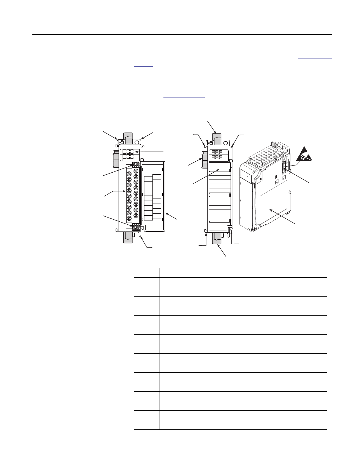
The module’s hardware features are illustrated in Figure 1. Refer to Chapter 3 on
page 45 for detailed information on installation and wiring.
For information about the packaged controllers’ hardware features, see the
CompactLogix Packaged Controllers Quick Start and User Manual,
publication
Figure 1 - Hardware Features
02
13
A0 B0
IN OUT
A1 B1Z0Z1
High Speed Counter
Do Not Remove RTB Under Power
Unless Area is Non-Hazardous
Ensure Adjacent
Bus Lever is Unlatched/Latched
Before/After
Removing/Inserting Module
IASIMP-QS010.
2a
DANGER
OUT DC
+5V/24V
OUT 0
OUT 1
OUT 2
OUT 3
OUT DC
COM
A0+
A0-
B0+
B0-
Z0+
Z0-
A1+
A1-
B1+
B1-
Z1+
Z1-
1769-HSC
9a
8a
3
02
13
A0 B0
IN OUT
A1 B1Z0Z1
High Speed Counter
8a
6a
10
4
7
6b
2b
8b
8b
9b
Item Description
1 Bus lever
2a Upper panel mounting tab
2b Lower panel mounting tab
3 Module status indicators (6 Input, 4 Output, 1 Fuse, 1 OK)
4 Module door with terminal identification label
5 Removable terminal block (RTB) with finger-safe cover
5a RTB upper-retaining screw
5b RTB lower-retaining screw
6a Movable bus connector (bus interface) with female pins
6b Stationary bus connector (bus interface) with male pins
7 Nameplate label
8a Upper tongue-and-groove slots
8b Lower tongue-and-groove slots
9a Upper DIN-rail latch
9b Lower DIN-rail latch
10 Write-on label for user identification tags
45271
Rockwell Automation Publication 1769-UM006E-EN-P - July 2013 13
Page 14
Chapter 1 Module Overview
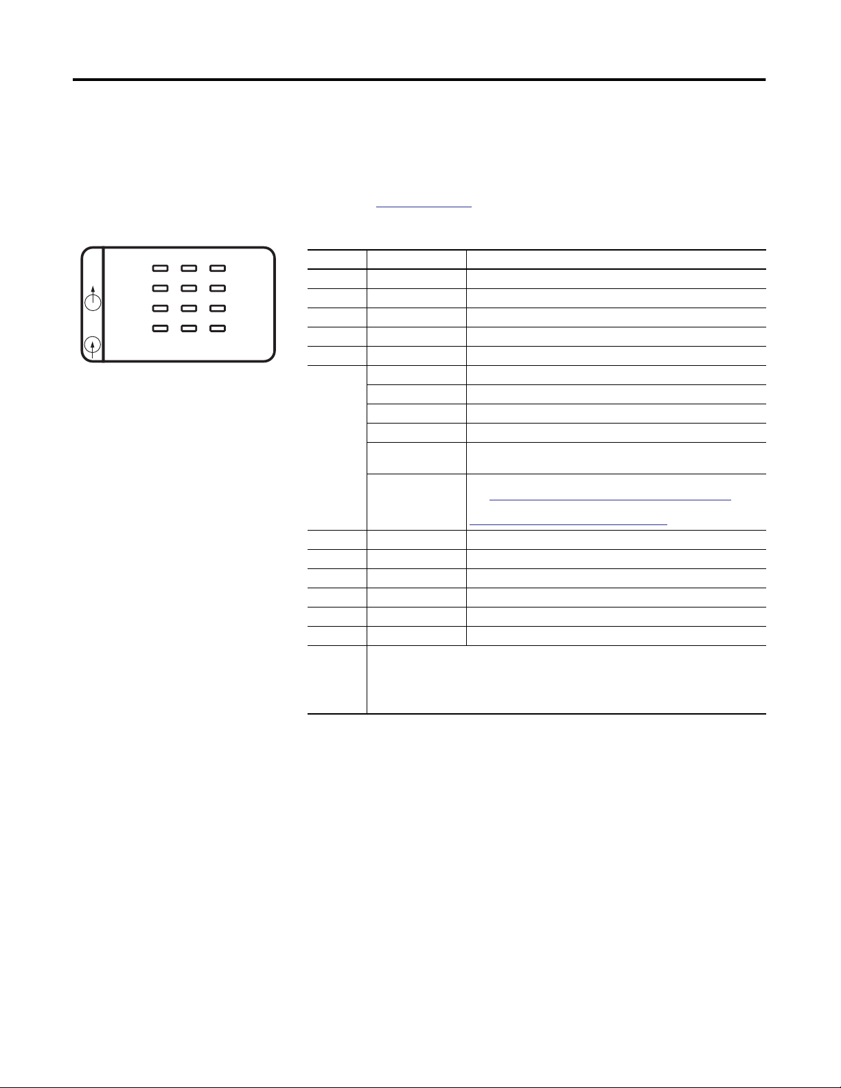
Status Indicators
0 2 FUSE
OUT
IN
13
AO BO ZO
A1 B1 Z1
High Speed Counter
OK
45272
The front panel of the 1769-HSC module has a total of 12 status indicators.
For information about the packaged controllers’ status indicators, see the
CompactLogix Packaged Controllers Quick Start and User Manual,
publication
Table 1 - Diagnostic Indicators
Indicator Status Description
0 OUT Amber ON/OFF logic status of output 0
1 OUT Amber ON/OFF logic status of output 1
2 OUT Amber ON/OFF logic status of output 2
3 OUT Amber ON/OFF logic status of output 3
FUSE Red Overcurrent
OK Off No power is applied
A0 Amber ON/OFF status of input A0
A1 Amber ON/OFF status of input A1
B0 Amber ON/OFF status of input B0
B1 Amber ON/OFF status of input B1
Z0 Amber ON/OFF status of input Z0
Z1 Amber ON/OFF status of input Z1
ALL ON Possible causes for all status indicators to be On include the following:
IASIMP-QS010.
Red (briefly) Performing self-test
Solid green OK, normal operating condition
Flashing green OK, module in Program or Fault mode
Solid red or amber Hardware error. Cycle power to the module. If problem persists,
Flashing red Recoverable fault. Reconfigure, reset, or perform error recovery.
• Bus error has occurred—controller hard fault. Cycle power.
• During load upgrade of controller—normal operation. Do not cycle power during the
load upgrade.
• All indicators flash on briefly during powerup—normal operation.
replace the module.
Non-critical versus Critical Module Errors on page 113. The
See
OK indicator flashes red for all of the error codes in the
Configuration Error Codes table on page 117.
14 Rockwell Automation Publication 1769-UM006E-EN-P - July 2013
Page 15

Chapter 2
Module Operation
This chapter details the operation of the 1769-HSC module. We strongly suggest
that you review this information before configuring your module.
Topic Page
Counter Defaults 15
Module Operation Block Diagrams 16
Number of Counters 18
Summary of Available Counter Configurations 18
Input Filtering 20
Operational Mode Selection 21
Input Frequency 28
Counter Types 28
Modifying Count Value 29
Rate/Timer Functionality 32
Output Control 36
Counter Defaults
When the module powers up, all output array and configuration array values are
set to their default values. Refer to
Chapter 4 on page 65 or Appendix D on page
149 for default values. All input array values are cleared. None of the module data
is retentive through a power cycle.
Power cycling the module has the following effects:
• Clears stored counts and configurations
• Clears faults and flags
• Turns outputs off
Rockwell Automation Publication 1769-UM006E-EN-P - July 2013 15
Page 16
Chapter 2 Module Operation
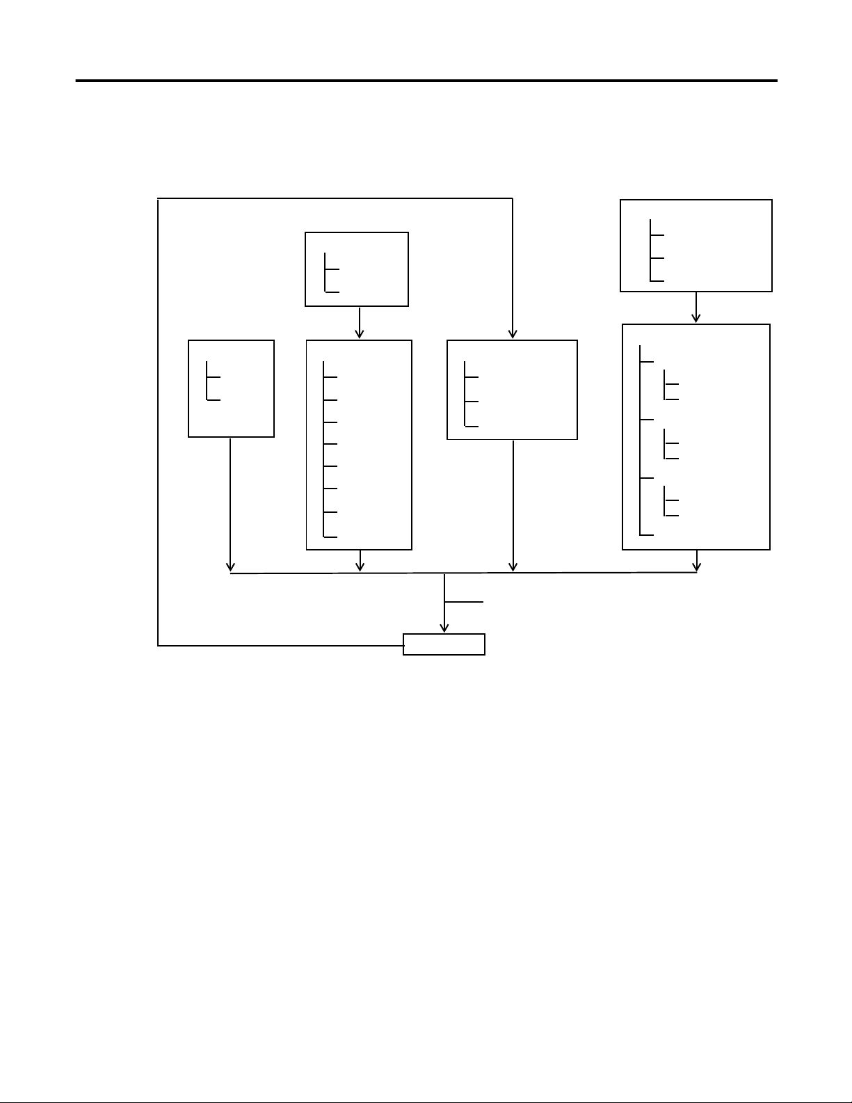
Module Operation Block Diagrams
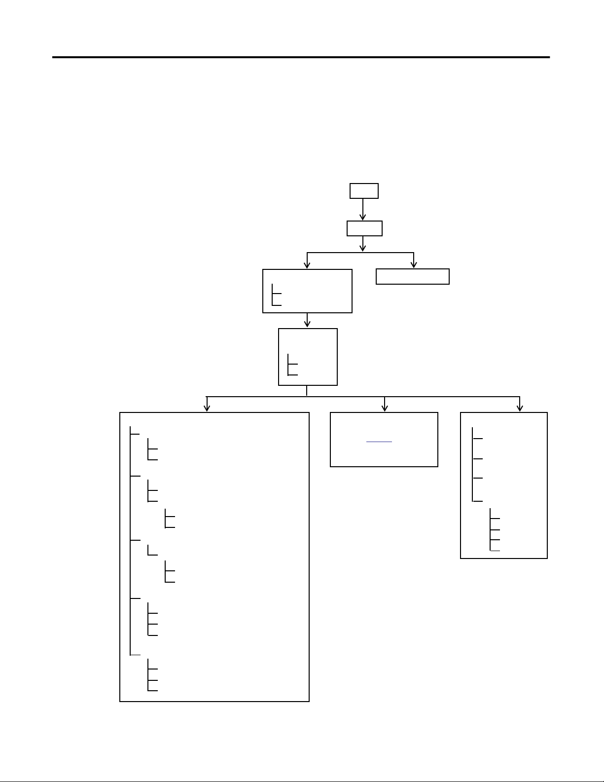
To provide an overview of the module operation, the block diagrams indicate
relationships between module functions and configuration parameters.
Inputs
The following diagram illustrates how the inputs function.
Input
Filtering
Decoded
NumberOfCounters
Operational Mode
Pulse
Direction
DirInvert
DirInhibit
Discrete Input State
Count
Min/Max and Linear/Ring
Overflow (ResetOvf)
Underflow (ResetUdf)
Store
CtrnConfig.StorageMode_0
RisingEdgeZ (reset REZ)
ZInhibit
ZInvert
Enable
CtrnEn
CtrnConfig.StorageMode_1
InputStateZn ‘gating’
Direct Write
HiLimOrDirWr
LoadDirectWrite
ToThisCounter
Preset
CtrnSoftPreset
CtrnConfig.StorageMode_2 and Rising Edge Z
Automatic PresetWarning (Preset Warning)
(1) Resets.
Pulse Interval
(1)
(1)
(2) Does not apply topackaged
controller.
(1)
(1)
(2)
See page 32 to
determine howandwhen
to use to calculate rates.
(3)
Rate
Update Time
Scalar
Hysteresis
Rate Valid
Overflow
Underflow
Preset
Direct Write
(3) Does not apply to
packaged controller.
16 Rockwell Automation Publication 1769-UM006E-EN-P - July 2013
Page 17
Module Operation Chapter 2
Outputs
The following diagram illustrates how the outputs function.
Mode
Discrete
On Mask
Off Mask
Feedback
Object Value
Current Count
Current Rate
Ranges
High Limit
Low Limit
Type
Invert
Counter
Active
Output Control
Range Enable
Run
Program
Fault
Mode (Program/Fault/Run)
Overcurrent
Overcurrent Flags
OverCurrentLatchOff
OverCurrentLatchOff
(1)
Output Real Only)
ResetBlownFuse
Readback (Real and Virtual)
Hold Last State
Program Mode
Fault Mode
User-defined Safe State
Program State
Fault State
Safe State Run
Program State Run
Fault State Run
Program to Fault Enable
(1) In the packaged controller, the Type parameter is fixed at Count because the
rate measurement is not supported.
Rockwell Automation Publication 1769-UM006E-EN-P - July 2013 17
Page 18

Chapter 2 Module Operation
Number of Counters
Summary of Available Counter Configurations
The module has six input points: A0, B0, Z0, A1, B1, and Z1. Through these
inputs, the module can function with 1, 2, 3, or 4 counters depending upon the
number of counters and the operational mode configuration of the input points.
The table summarizes the input configurations available for all counters, based on
the number of counters.
No. of Counters Counter Operational Mode Gate or Preset Functionality
1 Counter 0 Any All
1 through 3 Not available
2 Counters 0 Any All
1 Any All
2 and 3 Not available
3 Counters 0 Any All
1 Pulse/Internal Direction All
2 Pulse/Internal Direction None
3 Not available
4 Counters 0 Pulse/Internal Direction All
1 Pulse/Internal Direction All
2 Pulse/Internal Direction None
3 Pulse/Internal Direction None
18 Rockwell Automation Publication 1769-UM006E-EN-P - July 2013
Page 19
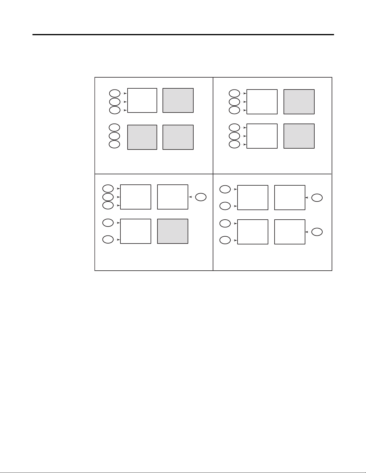
Module Operation Chapter 2
The counter options and operating modes are summarized in Figure 2.
Figure 2 - Summary of Available Counters
AO
BO
ZO
A1
Z1
AO
BO
ZO
A1
B1
Z1
Counter 0
Any Mode
Counter 1
Not Available
Counter 0
Any Mode
Counter 1
Pulse
Internal
1 Counter
3 Counters
Counter 2
Not Available
Counter 3
Not Available
(1)
Counter 2
Pulse
Internal
Counter 3
Not Available
(1)
B1
AO
ZO
A1
Z1
AO
BO
ZO
A1
B1
Z1
Counter 0
Any Mode
Counter 1
Any Mode
Counter 0
Pulse
Internal
Counter 1
Pulse
Internal
2 Counters
4 Counters
Counter 2
Not Available
Counter 3
Not Available
(1)
Counter 2
Pulse
Internal
Counter
Pulse
Internal
(1)
B1
BO
45273
(1) The number of counters is defined by the NumberOfCounters bits in word 0 of the configuration array.
Rockwell Automation Publication 1769-UM006E-EN-P - July 2013 19
Page 20
Chapter 2 Module Operation
Input Filtering
In many industrial environments, high frequency noise can be inadvertently
coupled to the sensor wires. The module can help reject some noise by means of
built-in filters. Inputs are filtered by means of user-selectable, low-pass filters
set up during module configuration.
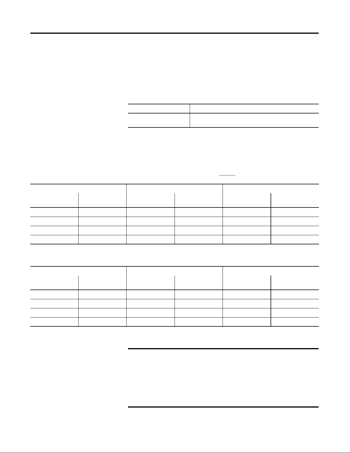
The available nominal pulse width filters are shown in the table.
Input Filter
A0, A1, B0, B1, Z0, Z1 5 ms, 500 s, 10 s, no filter
(7.1 ms, 715 s, 18.5 s, no filter for the packaged controller)
The filters are selected for each input in the Filter Selection word of the
module’s configuration array.
TIP
Nom Filter Settings Max Guaranteed Blocked Pulse Width Min Guaranteed Pass Pulse Width
Pulse Width Equivalent
Frequency
No filter 1 MHz N/A N/A 250 ns 2 MHz
10 µs 50 kHz 7.4 µs 67.5 kHz 25 µs 20 kHz
500 µs 1 kHz 370 µs 1.35 kHz 1.25 ms 400 Hz
5 ms 100 Hz 3.7 ms 135 Hz 12.5 ms 40 Hz
(1)
Pulse Width Equivalent
The input state bits (InputStateA0 through InputStateZ1) reflect the
filter’s inputs, but are NOT affected by the signal inhibit or invert
operations described on page 30.
Frequency
(1)
Pulse Width Equivalent
Frequency
(1)
(1)
(1) Equivalent frequency assumes a perfect 50% duty cycle and are for reference purposes only. Hence, the no-filter setting is guaranteed to pass 4 MHz even though the
module’s maximum is 1 MHz. This lets the sensor and wiring to attenuate the pulse to 25% duty cycle while the module maintains pulse recognition.
Nom Filter Settings Max Guaranteed Blocked Pulse Width Min Guaranteed Pass Pulse Width
Pulse Width Equivalent
Frequency
No filter 250 kHz 0.83 µs 600 kHz 2.5 µs 200 kHz
18.5 µs 27 kHz 12.3 µs 40.5 kHz 28.6 µs 17.5 kHz
715 µs 700 Hz 495 µs 1.01 kHz 1.25 ms 400 Hz
7.1 ms 70 Hz 4.95 ms 101 Hz 12.5 ms 40 Hz
(1) Equivalent frequency assumes a perfect 50% duty cycle and are for reference purposes only. Hence, the no-filter setting is guaranteed to pass 4 MHz even though the
module’s maximum is 1 MHz. This lets the sensor and wiring to attenuate the pulse to 25% duty cycle while the module maintains pulse recognition.
(1)
Pulse Width Equivalent
IMPORTANT
Frequency
The built-in filters are simple, averaging, low-pass filters. They are
(1)
Pulse Width Equivalent
Frequency
(1)
designed to block noise pulses of width equal to the values presented in
Table Filter Pulse Width and Frequency. Applying full amplitude, 50%
duty cycle signals that are of frequency above the selected filter’s
threshold frequency can result in an average value signal of sufficient
amplitude to turn the input on. A transition from no input to the full
amplitude, 50% duty cycle signal (or back to no signal) can result in
inadvertent input transitions.
(1) Low-pass filters block frequencies above the threshold frequency.
20 Rockwell Automation Publication 1769-UM006E-EN-P - July 2013
Page 21

Module Operation Chapter 2
Operational Mode Selection
A count channel’s operational mode configuration selection determines how the
A and B inputs cause a counter channel to increment or decrement. The six
available mode selections are the following:
• Pulse/External Direction Input
• Pulse/Internal Direction Input
• Up and Down Pulse Input
• X1 Quadrature Encoder Input
• X2 Quadrature Encoder Input
• X4 Quadrature Encoder Input
IMPORTANT
The operational mode selection is limited by the number of counters
selected.
• With two counters selected, Counters 0 and 1 can be assigned any
operational mode.
• With three counters selected, Counter 0 can be assigned any mode,
but Counters 1 and 2 can only be configured as pulse/internal
direction.
• With four counters selected, all counters must be configured for the
pulse/internal direction mode.
See
Figure 2 on page 19 for the operational modes available for the counters,
based on the number of counters configured.
Direction Inhibit and Direction Invert Output Control Bits
These bits apply to all of the counter modes.
TIP
When set, the Direction Inhibit bit disables any physical input from
affecting count direction.
When set, the Direction Invert bit changes the direction of the counter in
all operational modes.
When Direction Inhibit is set, then Direction Invert is the direction.
Rockwell Automation Publication 1769-UM006E-EN-P - July 2013 21
Page 22
Chapter 2 Module Operation
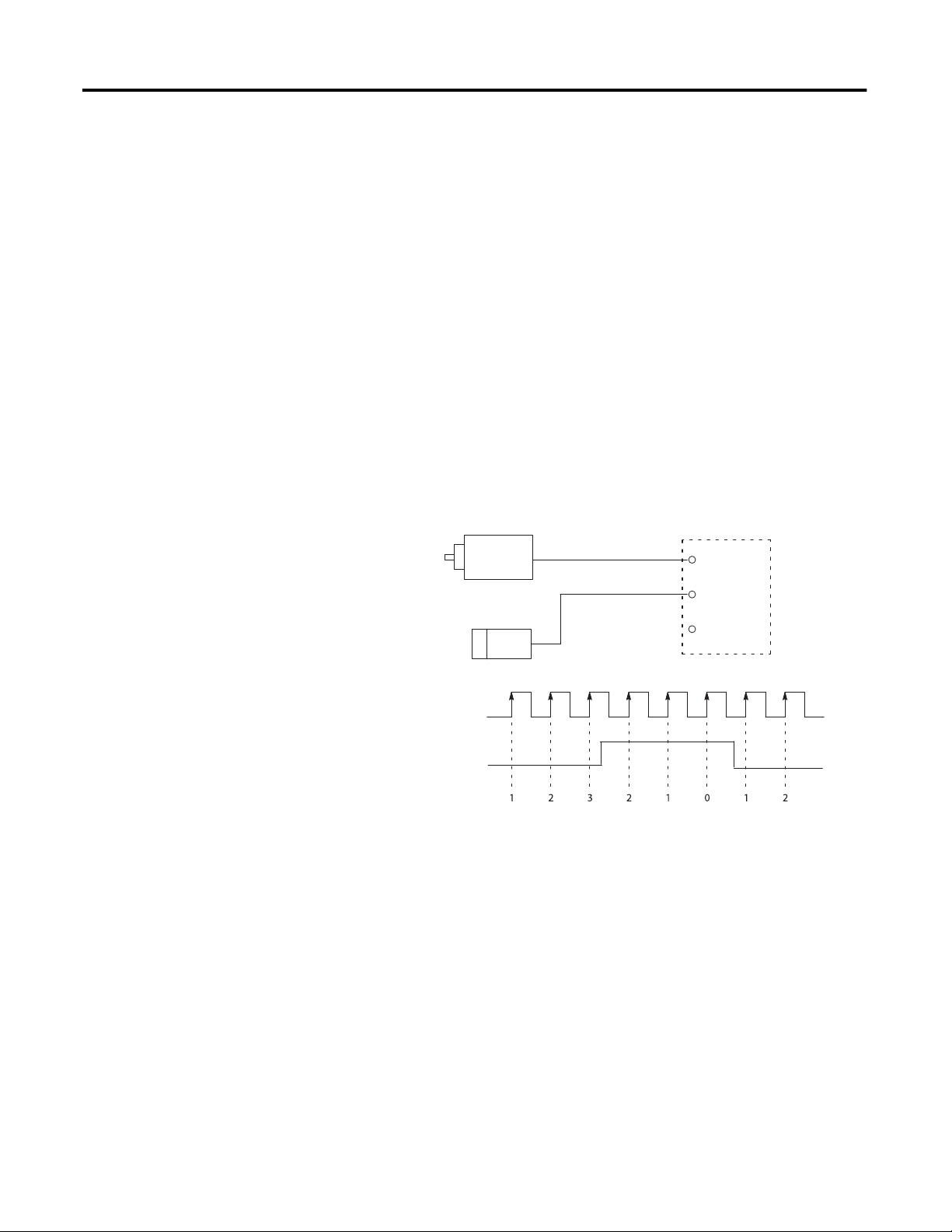
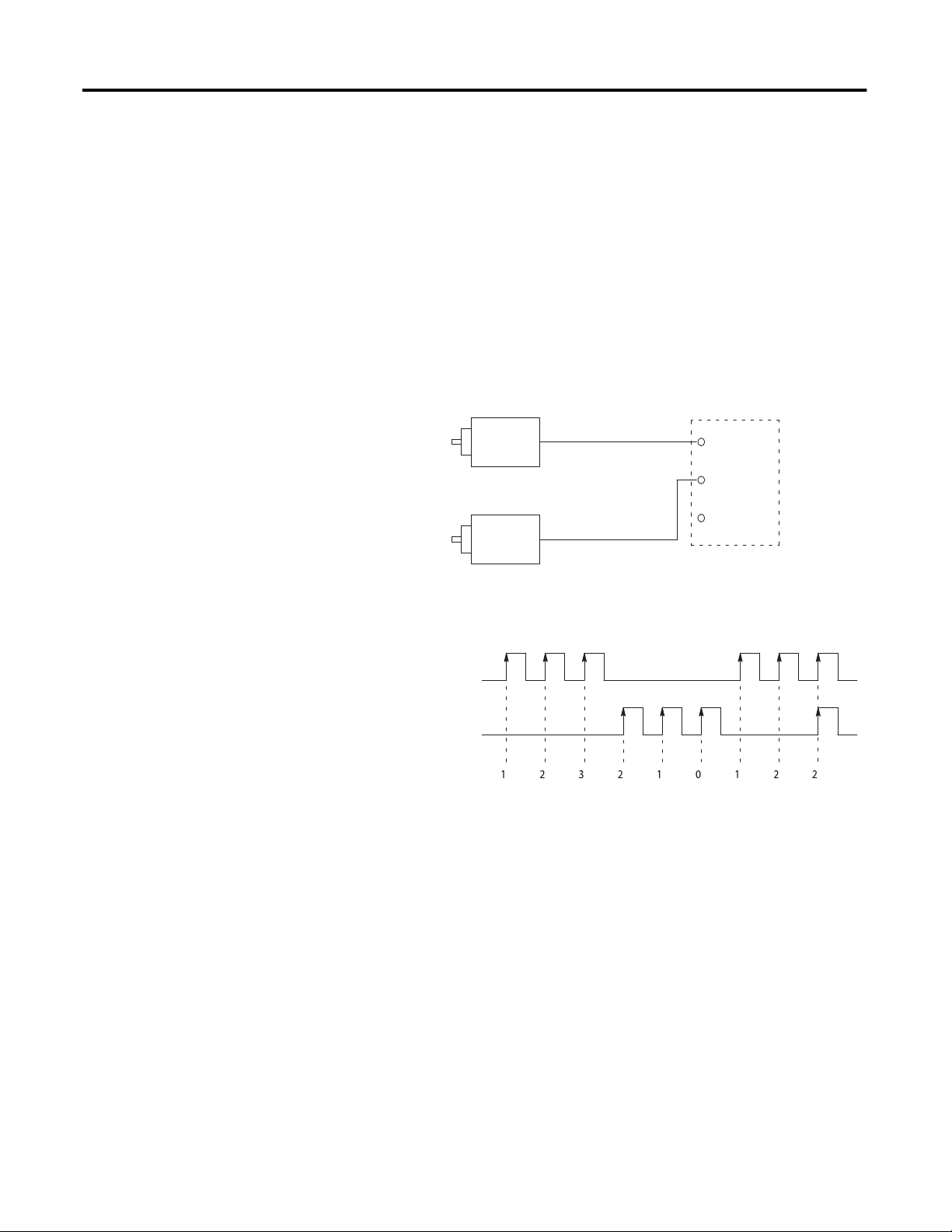
Pulse/External Direction Mode Selection
In this mode, the B input controls the direction of the counter, as shown in
Figure 3. If the B input is low (0), the counter increments on the rising edges of
input A. If the input B is high (1), the counter decrements on the rising edges of
input A.
TIP
Two Output Control bits let you modify the operation of the B input from
your control program or during configuration. The Direction Inhibit bit,
when set (1), disables the operation of the B input.
The Direction Invert bit, when set (1), reverses the operation of the
B input, but only if the Direction Inhibit bit is not set. If the Direction
Inhibit bit is set, then the Direction Invert bit controls counter direction:
• When the Direction Inhibit bit is set (1) and Direction Invert = 0, count
direction is up (forward).
• When the Direction Inhibit bit is set (1) and Direction Invert = 1, count
direction is down (reversed).
Figure 3 - Pulse/External Direction Mode (direction inhibit = 0, direction invert = 0)
Encoder or Sensor
Sensor or Switch
Count Pulse
Count Pulse
Direction Control
Input A
Input B
Input Z
Direction Control
High = Decrement
Low = Increment
22 Rockwell Automation Publication 1769-UM006E-EN-P - July 2013
Count
Page 23

Table 2 - Pulse External Direction Counting
Module Operation Chapter 2
Direction
Inhibit Bit
00 0 or open 1
01 0 or open -1
10 0 or open 1
11 0 or open -1
Direction
Invert Bit
Input A (count) Input B (direction) Change in
Count Value
1-1
0, 1, Don’t care 0
11
0, 1, Don’t care 0
11
0, 1, Don’t care 0
1-1
0, 1, Don’t care 0
See Direction Inhibit and Direction Invert Output Control Bits on page 21 for
more information.
Pulse/Internal Direction Mode Selection
When the Pulse/Internal Direction mode is selected, the status of the Direction
Invert bit, as controlled by the user program, determines the direction of the
counter. The counter increments on the rising edge of the module’s A input
when the Direction Invert bit is reset (0). The counter decrements on the rising
edge of the A input when the Direction Invert bit is set (1).
Table 3 - Pulse Internal Direction Counting - Counters 0 and 1
Direction
Inhibit Bit
Don’t care 0 Don’t care 1
Don’t care 1 Don’t care -1
Table 4 - Pulse Internal Direction Counting - Counters 2 and 3
Direction
Inhibit Bit
Don’t care 0 Don’t care 1
Don’t care 1 Don’t care -1
Direction
Invert Bit
Direction
Invert Bit
Input A (count) Input B Change in Count
Value
0, 1, Don’t care 0
0, 1, Don’t care 0
Input A Input B (count) Change in Count
Value
Don’t care 0, 1, 0
Don’t care 0, 1, 0
Rockwell Automation Publication 1769-UM006E-EN-P - July 2013 23
Page 24
Chapter 2 Module Operation
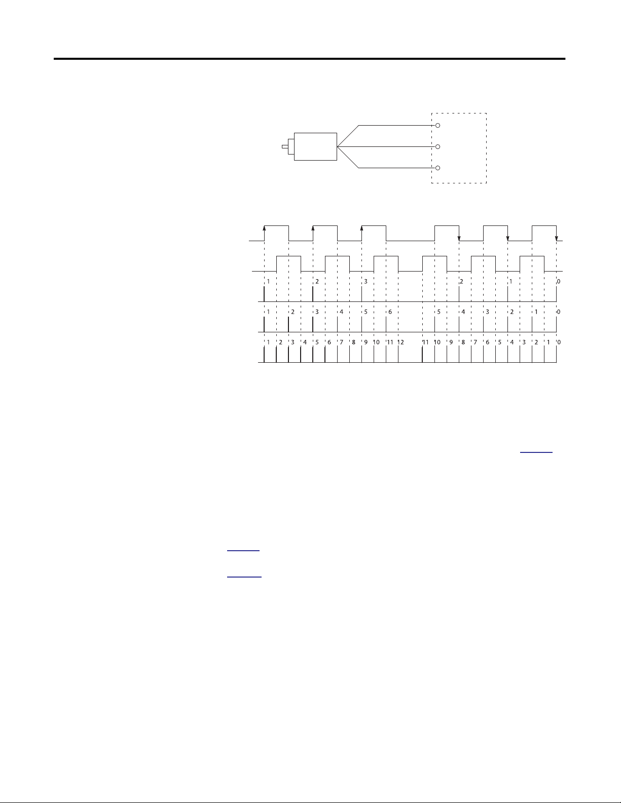
Up and Down Pulses Mode Selection
In this mode, the counter channel increments on the rising edge of pulses applied
to input A and decrements on the rising edge of pulses applied to input B. When
set, the Direction Inhibit bit causes both A and B to increment. When set, the
Direction Invert bit causes B to increment and A to decrement. When the
Direction Invert and Direction Inhibit bits are both set, both A and B
decrement.
TIP
When both inputs transition simultaneously or near simultaneously, the
net result is no change to the count value.
Figure4-UpandDown Pulse Mode (direction inhibit = 0, direction invert = 0)
Input A
Input B
Input Z
Module
Incrementing Encoder
Decrementing Encoder or
Increment Pulse
(Input A)
Decrement Pulse
(Input B)
Count
Increment Pulse
(count up)
or Sensor
Decrement Pulse
(count down)
Sensor
24 Rockwell Automation Publication 1769-UM006E-EN-P - July 2013
Page 25

Table5-UpandDown Counting
Module Operation Chapter 2
Direction
Inhibit Bit
00 0, 1, 1
01 0, 1, -1
10 0, 1, 1
11 0, 1, -1
Direction
Invert Bit
Input A (count) Input B (direction) Change in
Count Value
0, 1, -1
0
0, 1, 1
0
0, 1, 1
0
0, 1, -1
0
X1 Quadrature Encoder Mode Selection
In this mode, when a quadrature encoder is attached to inputs A and B, the count
direction is determined by the phase relation of inputs A and B. If A leads B, the
counter increments. If B leads A, the counter decrements. In other words, when B
is low, the count increments on the rising edge of input A and decrements on the
falling edge of input A. If B is high, all rising transitions on input A are ignored.
The counter changes value only on one edge of input A as shown in Figure 5.
TIP
When both A and B transition at the same time, instead of in the defined
90° phase separation, the quadrature signal is invalid.
For more information see
Direction Inhibit and Direction Invert Output
Control Bits on page 21 and their effect on Quadrature signals on page 27.
Rockwell Automation Publication 1769-UM006E-EN-P - July 2013 25
Page 26
Chapter 2 Module Operation
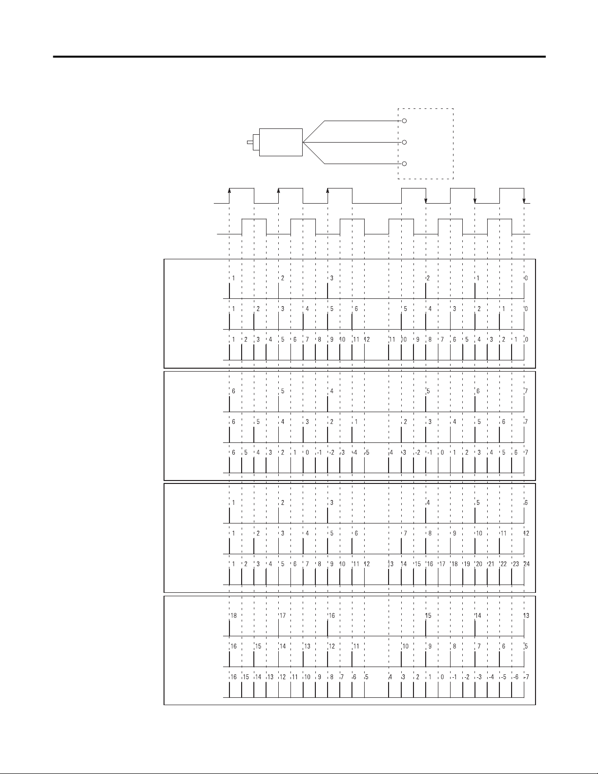
Figure 5 - Quadrature Encoder Modes (direction inhibit = 0, direction invert = 0)
A
B
Quadrature
Encoder
Forward Rotation
A
B
X1 Count
X2 Count
X4 Count
Z
X2 Quadrature Encoder Mode Selection
Input A
Input B
Input Z
Reverse Rotation
The X2 Quadrature Encoder mode operates much like the X1 Quadrature
Encoder except that the resolution is doubled as shown in Figure 5 on
page 26.
X4 Quadrature Encoder Mode Selection
The X4 Quadrature Encoder mode operates much like the X1 Quadrature
Encoder except that the resolution is quadrupled, as shown in Figure 5 on
page 26.
Figure 6 shows how Direction Inhibit and Direction Invert affect the counter.
26 Rockwell Automation Publication 1769-UM006E-EN-P - July 2013
Page 27
Module Operation Chapter 2
Figure 6 - Operation Using Various Direction Inhibit and Direction Invert Settings
Quadrature
Encoder
Forward Rotation
A
B
DirectionInhibit = 0; DirectionInvert = 0
X1 Count Pulse
X2 Count Pulse
X4 Count Pulse
DirectionInhibit = 0; DirectionInvert = 1
A
B
Z
Input A
Input B
Input Z
Reverse Rotation
X1 Count Pulse
X2 Count Pulse
X4 Count Pulse
DirectionInhibit = 1; DirectionInvert = 0
X1 Count Pulse
X2 Count Pulse
X4 Count Pulse
DirectionInhibit = 1; DirectionInvert = 1
X1 Count Pulse
X2 Count Pulse
X4 Count Pulse
Rockwell Automation Publication 1769-UM006E-EN-P - July 2013 27
Page 28
Chapter 2 Module Operation
Input Frequency
Counter Types
Maximum input frequency is determined by the input configuration as shown in
the table.
Input Configuration Input Frequency
1769-HSC Module
X4 Quadrature encoder 250 kHz 250 kHz
X2 Quadrature encoder 500 kHz 250 kHz
All other configurations 1 MHz 250 kHz
Input Frequency
Packaged Controller
Each of the four possible counters can be configured to stop counting and set a
flag at its limits (linear counter) or to rollover and set a flag at its limits (ring
counter). A counter’s limits are programmed by the CtrnMaxCount and
CtrnMinCount words in the module’s configuration array. Both types are
described below.
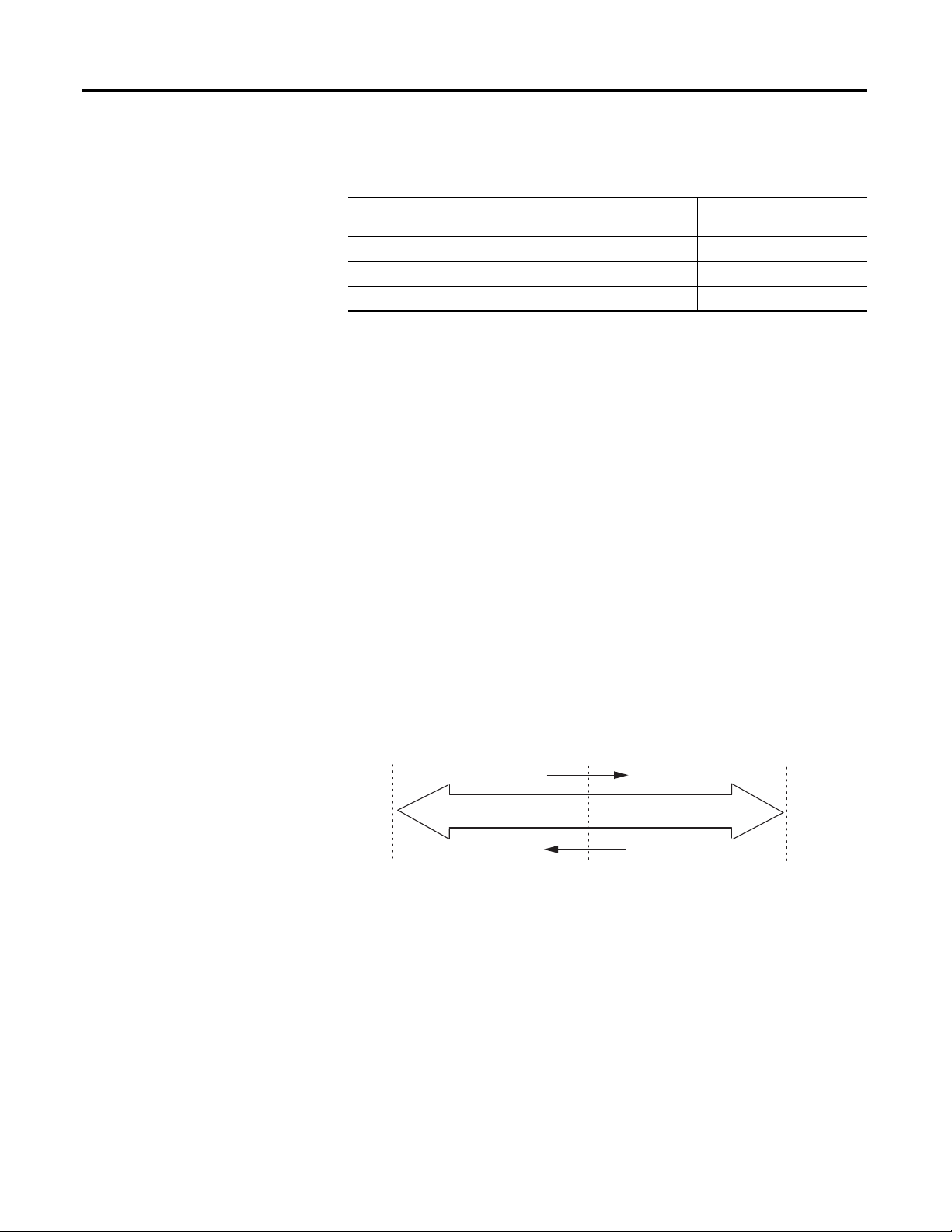
Linear Counter
Figure 7 illustrates linear counter operation. In linear operation, the current count
(Ctr[n].CurrentCount) value remains between, or equal to, the
user-programmed minimum count (CtrnMinCount) and maximum count
(CtrnMaxCount) values. If the Ctr[n].CurrentCount value goes above (>) or
below (<) these values, the counter stops counting, and an overflow/underflow
bit is set. The overflow/underflow bits can be reset using the
CtrnResetCounterOverflow and CtrnResetCounterUnderflow bits.
Figure 7 - Linear Counter Diagram
Minimum Count Value
Underflow and Hold
0
Count Up
Counter Value
Count Down
Maximum Count Value
Overflow and Hold
Pulses are not accumulated in an overflow/underflow state. The counter begins
counting again when pulses are applied in the proper direction. For example, if
you exceed the maximum by 1000 counts, you do not need to apply 1000 counts
in the opposite direction before the counter begins counting down. The first
pulse in the opposite direction decrements the counter.
28 Rockwell Automation Publication 1769-UM006E-EN-P - July 2013
Page 29

Module Operation Chapter 2
Ring Counter
Figure 8 demonstrates ring counter operation. In ring counter operation, the
current count (Ctr[n].CurrentCount) value changes between user-programmable
minimum count (CtrnMinCount) and maximum count (CtrnMaxCount)
values. If, when counting up, the counter reaches the CtrnMaxCount value, it
rolls over to the CtrnMinCount value upon receiving the next count and sets the
overflow bit. If, when counting down, the counter reaches the CtrnMinCount
value, it rolls under to the CtrnMaxCount value upon receiving the next count
and sets the underflow bit. These bits can be reset using the
CtrnResetCounterOverflow and CtrnResetCounterUnderflow bits.
Figure 8 - Ring Counter Diagram
Modifying Count Value
Maximum Count Value
Rollover
Count Down
Minimum Count Value
Count Up
The count value (Ctr[n].CurrentCount) can be stored, reset, or preset using the
Z-input, CtrReset bit in the configuration array, control bits in the output array,
or overwritten using a Direct Write command.
Table6-Available Z Functions
Setting For function
(1)
Store
Hold WhileZ=1,hold counter at its current value
Preset/Reset On rising edge of Z, preset the count value to the value in the preset word
(1) If both a store and preset function are configured, the stored count is captured before the preset operation
takes place.
On rising edge of Z, store count in the Stored Count input word
IMPORTANT
Rockwell Automation Publication 1769-UM006E-EN-P - July 2013 29
Because only the Z-inputs are used for external gating and presetting,
these functions are not available for Counters 2 and 3, which do not have
Z-inputs. All options are always available for Counters 0 and 1,
regardless of input operational mode.
Page 30

Chapter 2 Module Operation
Counter Enable/Disable
The counter can be enabled or disabled using the CtrnEn control bit. Be aware
that disabling the counter does not inhibit any current count loading functions
(for example, preset or direct write) or any Z function.
Z Input Functions
There are three Z input functions: store, gate, and Z preset.
Store
The Z-input can be used to capture the current count value even when the
counter is counting at full 1 MHz speed.
Gate
The Z-inputs can be used to gate (hold) the counter at its current value regardless
of incoming A or B inputs. A gating function is typically one that lets pulses reach
the counter (gate open) or not (gate closed).
Z Preset
Preset can be programmed to occur based on the actions of the Z-input signal.
Inhibit and Invert
The Z-input signals can be inverted and/or inhibited, depending on the user
configuration of the CtrnZInvert and CtrnZInhibit output control bits. If the
signal is inhibited, the invert bit is the Z signal for the actions described above.
For an explanation of those bits, see
Z Inh - Z Inhibit (CtrnZInhibit) on page 93.
and
Z Inv - Z Invert (CtrnZInvert) on page 93
Direct Write
You can arbitrarily change the current count value (Ctr[n].CurrentCount) to the
direct write control value (Range12To15[n].HiLimOrDirWr). This ability
applies to ranges 12…15. The direct write value takes effect when the Load Direct
Write bit (Range12To15[n].LoadDirectWrite) transitions from 0 to 1.
If you attempt to preset and load direct write to a counter at the same time, only
the preset (CtrnPreset) will take effect.
30 Rockwell Automation Publication 1769-UM006E-EN-P - July 2013
Page 31

Module Operation Chapter 2
Preset/Reset
Preset sets the counter to a zero or non-zero value you define. Reset the counter
by setting this value (CtrnPreset) to zero.
Counter Reset
Refer to page 73 in Chapter 4 for details on performing a default counter reset for
the CMX 5370 L2 packaged controller and the 1769-HSC/B module only. The
L23E packaged controller and the 1769-HSC/A module do not have this
functionality.
Soft Preset
Preset can be programmed to occur by setting the appropriate output control bits
via your control program. Setting the CtrnSoftPreset bit in the output array
causes the counter to be preset, changing the count to the value in CtrnPreset.
Z Preset
Preset can be programmed to occur based on the actions of the Z-input signal.
Autopreset
If the module is configured such that CtrnMaxCount < Ctr[n].CurrentCount or
CtrnMinCount > Ctr[n].CurrentCount, then the module will automatically
change Ctr[n].CurrentCount to the CtrnPreset value and set the
CtrnPresetWarning bit.
Rockwell Automation Publication 1769-UM006E-EN-P - July 2013 31
Page 32

Chapter 2 Module Operation
Rate/Timer Functionality
To ensure maximum accuracy, the module offers two different methods to
calculate the rate.
• Per Pulse = 1/Pulse Interval
• Cyclic = Number of Pulses/User-defined Time Interval
You select the method used, depending upon the pulse speed as defined below.
These are continuously available regardless of input operational mode.
IMPORTANT
The Rate/Timer Functionality information does not apply to the
L23E packaged controller.
Pulse Interval Rate Calculation Method
Pulse Interval = 100 µs
Frequency = 1/100 µs = 10,000 Hz
The pulse interval rate method is very accurate for slower rates, that is, when the
pulse interval (or time between pulses) is large compared to the system clock
timer (1 μs). A timer is used to measure the time between two successive pulses.
The inverse of this value is the pulse interval rate. The pulse interval rate cannot
be read directly from the module. It needs to be calculated. The calculation can be
performed in the user control program.
This method is not as accurate for higher pulse rates. When the pulse interval
shrinks, two factors can distort the per pulse calculation. If the pulse interval is
close to the measuring timer’s clock frequency, 1 MHz, the granularity of the time
increments has a greater effect on rate inaccuracy. In addition, the rate can be
calculated many times over the course of a single backplane scan. As a result, the
rate data obtained at a backplane scan is only that of the very last pair of pulses
and disregards the other rate calculations that have occurred during that interval.
This can result in rate inaccuracy if the pulses are unevenly spaced.
Cyclic Rate Calcu
The module continuously calculates rates for each of its four possible counters,
regardless of operational mode (for example, up/down count). The 32-bit signed
integer rate from each counter is reported in the Ctr[n].CurrentRate words of the
input array.
In this method, the rates are calculated at the end of a counter’s configured cycle
time. This is configured via the CtrnCyclicRateUpdateTime configuration
word/menu. Valid entries are 1…32,767 ms. The number of net counts, net
change in Ctr[n].CurrentCount, during that period is converted into a rate value,
providing an average pulse rate.
lation Me
thod (current rate)
32 Rockwell Automation Publication 1769-UM006E-EN-P - July 2013
Page 33

Module Operation Chapter 2
The generalized rate calculation is Rate = count/ time.
IMPORTANT
The rate calculation is based on net counts. If a counter goes up 500
counts and down 300 counts, the net count is 200. Therefore, changes in
direction and speed affect the Ctr[n].CurrentRate value.
The cyclic method is better suited to high pulse rates.
Hysteresis Detection and Configuration
Because physical vibration can cause an encoder to generate pulses that you do
not wish to consider as valid motion, a hysteresis value is used to eliminate a
certain number of pulses in either direction as vibration-generated. These pulses
are not used to calculate the Ctr[n].CurrentRate value. You program the
minimum number of counts that are considered to be valid motion, using the
CtrnHysteresis configuration word/menu. If the change in counts over the
update time cycle is equal to or less than the minimum number of programmed
counts, the Ctr[n].CurrentRate is reported as zero.
This concept is not used to alter actual count values.
IMPORTANT
Hysteresis does not depend on the direction of the change in count.
Therefore, creeping, a slow change in count in one direction only, can
also be reported as zero frequency when it falls below the hysteresis
threshold.
Rockwell Automation Publication 1769-UM006E-EN-P - July 2013 33
Page 34

Chapter 2 Module Operation
Scalar
You can configure the CtrnScalar value to scale or convert the raw rate value to
application-specific information, such as RPM (Revolutions Per Minute). Setting
CtrnScalar to 1 leaves the rate value in cycles per second (Hertz).
The actual rate equation is the following.
Current Rate =
TIP
1000 x count
CyclicRateUpdateTime x Scalar
To configure the Ctr[n].CurrentRate value to show an RPM value, set
CtrnScalar to (counts per revolution)/60.
For example, where Ctr0CyclicRateUpdateTime = 80, the encoder has 360
counts per revolution, and the change in Ctr[0]. CurrentCount is 96.
Scalar =
RPM =
360 counts/revolution
60 sec/min
1000 Cyclic Rate Update Time/sec x 96 counts
80 Cyclic Rate Update Time x 360 counts/revolution
60 sec/min
= 200 RPM
Rate Valid
The Ctr[n].RateValid bit indicates calculation integrity. When the bit is set, it
indicates that the accompanying Ctr[n].CurrentRate value is accurate.
The Ctr[n].RateValid bit is reset when the overflow or underflow events have
occurred, that is, at rising edges of Ctr[n].Overflow or Ctr[n].Underflow bits. It
also happens when the count is abruptly modified via a preset (CtrnSoftPreset,
CtrnCtrPresetWarning or Z based preset event) or direct write
(Range12To15[n].LoadDirectWrite). When this occurs, the Ctr[n].CurrentRate
value is frozen at the last known good value so that effects of erroneous rates will
not propagate to range comparisons. The value remains frozen until the current
cycle time plus one more cycle time are elapsed (this can be up to twice the
CtrnCyclicRateUpdateTime). If the overflow/underflow occurrence lasts for
more than one cycle time, the value is frozen that entire time plus up to two more
cycle times.
Ensure that another overflow/underflow does not happen during this recovery
time. The rate will remain invalid until a full update time has occurred with no
such events. If the Ctr[n].RateValid bit is seldom or never set, the CtrnMinCount
and CtrnMaxCount values can be configured too close to each other.
34 Rockwell Automation Publication 1769-UM006E-EN-P - July 2013
Page 35

Module Operation Chapter 2
Rate Method
Selectio
n
By knowing when to use each method, an optimal rate determination can be
made.
TIP
Fractional rates are not reported by the module, but can be calculated
from Ctr[n].PulseInterval in your control program.
Use the following information to choose the appropriate calculation method. In
general, consider the effect of having the count off by ±1 in each method at
frequencies of interest to see if the resulting inaccuracy is acceptable.
Per Pulse Method Example
If the frequency of interest has 100 counts (of the 1 μs clock) between pulses, an
error of 1 count results in a 1-in-100, or 1%, error. If there are 1000 counts
between pulses, then the error is 1-in-1000, or 0.1%. Error for a variety of pulse
values is shown below.
Table 7 - Per Pulse Errors
Actual 1 µs
Internal
(1)
Pulses
2 1 500 kHz 1 MHz 100%
9 10 111 kHz 100 kHz 11.1%
101 100 9.901 kHz 10.000 kHz 1.00%
1001 1000 999 Hz 1000 Hz 0.10%
9999 10,000 100.01 Hz 100.00 Hz 0.010%
99,999 100,000 10.00010 Hz 10.00000 Hz 0.001%
Reported
Pulses
Real Frequency Reported
Frequency
% Error
(1) 1.9999 can be rounded to 2 and so on.
Cyclic Method
Because the update time is programmable, there is more flexibility in choosing the
correct fit when using the Cyclic Method.
Error estimates are shown below for a variety of update times.
Table 8 - Maximum Cyclic Rate Errors
CyclicRateUpdate
Time x Scalar
1 N/A N/A 20.02% 2.011% 0.210%
10 N/A 20.11% 2.020% 0.210% 0.030%
100 20.01% 2.110% 0.220% 0.031% 0.012%
1000 3.010% 0.310% 0.040% 0.013% 0.010%
10,000 1.210% 0.130% 0.022% 0.011% 0.010%
Rockwell Automation Publication 1769-UM006E-EN-P - July 2013 35
Frequency
100 Hz 1 kHz 10 kHz 100 kHz 1 MHz
Page 36

Chapter 2 Module Operation
Output Control
All 16 outputs can be controlled by any of the four counters or by the user’s
control program, via the output mask function. Output states are determined by
count, rate (not supported in packaged controller), ranges, mask configuration
data, overcurrent status, and safe state settings and conditions.
The 16 outputs are made up of four real (physical) outputs and 12 virtual
outputs. The status of the real and virtual outputs is available to the user
program. The real outputs are electronically protected from overloads.
IMPORTANT
To turn outputs on, you must use both the Output On Mask and
the Output Off Mask.
Masks
You can use an Output On Mask or an Output Off Mask.
Output On Mask
Using the Output On Mask, all of the module’s outputs can be turned on directly
by the user control program, like discrete outputs. A bit that is set in the mask
turns on the corresponding real or virtual output.
Output Off Mask
The Output Off Mask has veto power over any output. It can turn any or all of
the module’s outputs off. When a bit in this mask is set to 0, the output will be
turned off. Each bit is logically ANDed with the Output On Mask and masks of
active and enabled ranges. If the bit in this mask is set to 1, the output can be
turned on or off by the ranges, or the Output On Mask. The final result is
available as the Readback.n bit.
36 Rockwell Automation Publication 1769-UM006E-EN-P - July 2013
Page 37

Module Operation Chapter 2
Ranges
For the 1769-HSC module and the embedded HSC in the CMX 5370 L2
packaged controllers, up to 16 dynamically configurable ranges are available.
Ranges activate outputs based on the current count value or the current rate
value. Each range is programmed with a type, counter number, two limit values,
an invert bit, and an output mask.
For the embedded HSC in the L23E packaged controller, up to four dynamically
configurable ranges are available. Ranges activate outputs based on the current
count value. Each range is programmed with a counter number, two limit values,
an invert bit, and an output mask.
Each range is programmed with high and low limits for the chosen value. The
range’s invert bit indicates whether the range is active between or outside the
range limits. When the chosen value fulfills the configuration parameters, the
range is active as indicated in the input array. When a range is active and enabled
(RangeEn.n = 1), the range turns on all outputs indicated by the Range Output
Mask except those that are prevented from being enabled by the other factors
such as Output Off Mask or Overcurrent. The status of a range is provided by the
range active status word, where 1 equals range active and zero equals inactive.
TIP
Ranges can be disabled while the module is running using the RangeEn.n
bit in the output file. However, even a disabled range will report when it
is active or not. For example, an unprogrammed range has limits of 0, and
points to the Ctr[0].CurrentCount value. If this value is 0, that range is
reported as active.
Rockwell Automation Publication 1769-UM006E-EN-P - July 2013 37
Page 38

Chapter 2 Module Operation
Count Range
In a non-inverted count range, the outputs are active if the count value is within
the user-defined range. In an inverted count range, the outputs are active if the
count value is outside the user-defined range. Valid limits for the range are
-2…2 billion regardless of programmed minimum and maximum values.
Figure 9 shows all ranges referring to one counter. The module is capable of
individually assigning each range to any counter. Each counter can also have a
combination of count and rate ranges.
Figure 9 - Count Range Example
-200,000 106,000
Range 4
Stop Value
On
Output 0
Off
Output 1
Output 2
Output 3
Table 9 - Count Range Example Values
0
Ctr[0].CurrentCount
Range 1 Range 2 Range 4
Start Value
Outputs
Range 3
(2)
(Range[n].OutputControl word)
(1)
15 14 13 12 11 10 9 8 7 6 5 4 3 2 1 0
Range
Range Counter Number
Range Type
Range Low Limit
1 01 0 -7000 -5000 0 0 0 0 0 0 0 0 0 0 0 0 0 0 0 0 1 0
2 01 0 -1000 4500 0 0 0 0 0 0 0 0 0 0 0 0 0 0 0 1 0 1
3 01 0 -4000 3000 0 0 0 0 0 0 0 0 0 0 0 0 0 0 1 0 0 2
4 01 0 -9000 9000 1 0 0 0 0 0 0 0 0 0 0 0 0 1 0 0 1 0 and 3
(1) For Range Type, 0 = count range and 1 = rate range.
(2) Bits 0…3 are real outputs. Bits 4…15 are virtual outputs.
38 Rockwell Automation Publication 1769-UM006E-EN-P - July 2013
Range High Limit
Range Invert Bit
Outputs Affected
Page 39

Rate Range
Module Operation Chapter 2
IMPORTANT
The Rate Range information does not apply to the packaged controller.
In a non-inverted rate range, the outputs are active if the rate measurement is
within the user-defined range. In an inverted rate range, the outputs are active if
the rate measurement is outside the user-defined range. The input rate can be up
to 1 MHz in either direction.
Figure 10 shows all ranges referring to one counter. The module is capable of
individually assigning each range to any counter. Each counter can also have a
combination of count and rate ranges.
Figure 10 - Rate Range Example
-1,000,000 1,000,000
Range 4 Range 1 Range 2 Range 4
Range 3
On
Output 0
Off
0
Ctr[0].CurrentRate
Output 1
Output 2
Output 3
Table 10 - Rate Range Example Values
(2)
Outputs
(1)
Range
Range Counter
Number
Range Type
Range Low Limit
1 00 1 -7000 -5000 0 00000000000000010
2 00 1 -1000 4500 0 00000000000000101
3 00 1 -4000 3000 0 00000000000001002
4 00 1 -20,000 20,000 1 00000000000010010and3
(1) For Range Type, 0 = count range and 1 = rate range.
(2) Bits 0…3 are real outputs. Bits 4…15 are virtual outputs.
Range High Limit
(Range[n].OutputControl word)
1514131211109876543210
Range Invert Bit
Outputs Affected
Rockwell Automation Publication 1769-UM006E-EN-P - July 2013 39
Page 40

Chapter 2 Module Operation
Overcurrent
If the module detects a real output point overcurrent condition, it reports it to
the input file and turns off that output. You can also program the module to
latch each of the four real outputs off, emulating a physical fuse, or to
automatically reset. The 12 virtual outputs do not have this function.
When the OvercurrentLatchOff bit is set and an overcurrent situation occurs,
even momentarily, the associated real output is latched off until the
ResetBlownFuse bit transitions from 0 to 1.
If the OvercurrentLatchOff bit is reset and an overcurrent situation occurs, the
output turns off for 1 second and is then retried (auto-reset). The module
continues to attempt to turn the output back on until the overcurrent situation is
no longer detected and the output is successfully turned back on.
IMPORTANT
The outputs will be on momentarily while they are retried. The length of
time they are on depends on the magnitude of the load.
Safe State Control
The 1769-HSC module combines the Hold Last State and User-defined Safe
State options with a safe-state run alternative that lets the module to continue to
control outputs under program or fault states
available in the packaged controllers.
Only the physical outputs are affected by safe state settings and conditions.
Virtual outputs, inputs, and counting are not affected by program or fault states.
Hold Last State (HLS)
This condition applies depending on the mode of the controller. When the hold
last state option is set, the module holds the outputs at the state they were at just
before the control system transitioned from Run to Program or Run to Fault.
HLS sets the module according to the values configured for Program mode
(described on
page 76) and Output Fault mode (described on page 77).
(1)
. These Safe State options are not
User-defined Safe State (UDSS)
In this configuration, the module sets the outputs to a user-defined safe state
when the control system transitions from Run to Program or Run to Fault.
UDSS sets the module according to the values configured for Output Program
Value (described on
(1) The module continues to update the input array and count inputs in all modes. The operation of the outputs will
vary according to mode, configuration, and the capabilities of the controller or bus master.
40 Rockwell Automation Publication 1769-UM006E-EN-P - July 2013
page 77) and Output Fault Value (described on page 78).
Page 41

Module Operation Chapter 2
Program State Run (PSR)
Program State Run lets you specify that the output should continue to be
controlled by the module as if it were in the Run state. That is, events on the
module or changes in the output image will affect the physical outputs without
regard to the Program_HLS or UDSS state indicated. When this bit is set, the
corresponding OutnProgramMode and OutnProgramValue bits are ignored.
PSR sets the module according to the value configured for Output Program State
Run, as described on
ATTENTION: Selecting this option lets outputs change state while ladder
logic is not running. You must take care to assure that this does not pose a
risk of injury or equipment damage when selecting this option.
page 76.
IMPORTANT
The prescan initiated by some controllers could have an effect on the
outputs. To overcome any changes in physical output states caused by
this, retentive output instructions (for example, latch or unlatch) should
be used when bit manipulations are done on the output image of this
module in ladder logic.
This applies to a wide range of bits when Program State Run is selected,
because presetting a counter, enabling a range, changing a mask, and
changing module configuration array settings can cause ranges and
outputs to change state.
Rockwell Automation Publication 1769-UM006E-EN-P - July 2013 41
Page 42

Chapter 2 Module Operation
Fault State Run (FSR)
Similar to Program State Run, Fault State Run lets you specify, on a bit basis, that
the output should continue to be controlled by the module as if it were Run state.
That is, events on the module or changes in the output image will affect the
physical outputs without regard to the Fault_HLS or UDSS state indicated.
When this bit is set, the corresponding Fault mode and fault value bits are
ignored.
FSR sets the module according to the value configured for Output Fault State
Run, as described on
page 77.
ATTENTION:Selecting this option lets outputs change state while
ladder logic is not running. You must take care to assure that this
does not pose a risk of injury or equipment damage when selecting
this option.
IMPORTANT
The prescan initiated by some controllers can have an effect on the
outputs. To overcome any changes in physical output states caused by
this, use retentive output instructions (for example, latch or unlatch)
when bit manipulations are done on the Output image of this module
in ladder logic.
This applies to a wide range of bits when Fault State Run is selected,
because presetting a counter, enabling a range, changing a mask, and
changing configuration array settings can cause ranges and outputs to
change state.
42 Rockwell Automation Publication 1769-UM006E-EN-P - July 2013
Page 43

Module Operation Chapter 2
Program to Fault Enable (PFE)
The ProgToFaultEn bit lets you select which data value (Program Value or Fault
Value) to apply to the output when the Output State Logic state Prog_HLS
changes to indicate Fault_HLS.
If PFE is 0, the module leaves the Program value applied. If PFE is set to 1, the
Fault value is applied.
TIP
If the module is in a safe state such as Program or Fault which is
configured to turn an output ON and excessive current is drawn from the
output, the output will still turn off according to the programmed
OverCurrentLatchOff bit configuration.
The module’s Default Safe State configuration is all zeros, resulting in the
following:
• Program State = UDSS
• Program Value = OFF
• Program State Run = No
• Fault State = UDSS
• Fault Value = OFF
• Fault State Run = No
• PFE = leave program value applied
Output Control Example
The following example illustrates the module’s output control flow. The
following conditions are reflected in the
• Range 0 is enabled and active.
• Range 1 is disabled.
• Range 2 is enabled but not active.
• An overcurrent condition exists on real output 3.
• OvercurrentLatchOff is set.
• The system is in Run mode.
Output Control Example on page 44:
Rockwell Automation Publication 1769-UM006E-EN-P - July 2013 43
Page 44

Chapter 2 Module Operation
Table 11 illustrates the step-by-step logical operations that are performed to
determine the final output state. For example, Range 1 values do not affect the
output because Range 1 is disabled, and the Output Off Mask causes some of the
outputs to change to zero because it takes priority over the range masks.
The output parameters shown have been discussed in the previous sections.
Table 11 - Output Control Example
Output Parameter Mask Information Logical Operation Result
Range 0 0 001011011010001OR 0001011011010001
Range 1 0 010111111110010OR 0001011011010001
Range 2 0 100000000001100OR 0001011011010001
Output On Mask 0 100101010101000OR 01 011 110111 1 1 001
Output Overcurrent - -----------1000AND 0101111011110 001
Output Off Mask 1 111000011111100AND 0101000011110000
Program State
Values
Fault State Values - -----------11 1 1 Override 0 101000011110000
Final Output State 0 101000011110000
------------11 1 1 Override 0 101000011110000
(1)
(1) Bolded text indicates that these values have changed.
Readback/Loopback
The Readback/Loopback function is the feedback of the module’s outputs via its
input array. This 16-bit image includes both real (4) and virtual (12) outputs.
If the module’s output is OFF due to overcurrent, both the Overcurrent status
flag and the Readback bit will indicate the condition being 1 and 0, respectively.
Conversely, should the output be ON due to any module control, such as UDSS,
this will be indicated by Readback.
44 Rockwell Automation Publication 1769-UM006E-EN-P - July 2013
Page 45

Chapter 3
Installation and Wiring
This chapter explains how to install and wire the 1769-HSC module.
Topic Page
Power Requirements 47
General Considerations 47
System Assembly 49
Mount the Module 50
Replace the Module within a System 53
Field Wiring Connections 54
IMPORTANT
ATTENTION: Environment and Enclosure
This equipment is intended for use in a Pollution Degree 2 industrial environment, in overvoltage Category II
applications (as defined in IEC 60664-1), at altitudes up to 2000 m (6562 ft) without derating.
This equipment is considered Group 1, Class A industrial equipment according to IEC/CISPR 11. Without appropriate
precautions, there can be difficulties with electromagnetic compatibility in residential and other environments due to
conducted and radiated disturbances.
This equipment is supplied as open-type equipment. It must be mounted within an enclosure that is suitably designed
for those specific environmental conditions that will be present and appropriately designed to prevent personal injury
resulting from accessibility to live parts. The enclosure must have suitable flame-retardant properties to prevent or
minimize the spread of flame, complying with a flame spread rating of 5VA, V2, V1, V0 (or equivalent) if non-metallic.
The interior of the enclosure must be accessible only by the use of a tool. Subsequent sections of this publication may
contain additional information regarding specific enclosure type ratings that are required to comply with certain
product safety certifications.
In addition to this publication, see the following:
For information about installing and wiring the packaged controllers,
refer to the CompactLogix Packaged Controller Installation Instructions,
publication 1769-IN082.
• Industrial Automation Wiring and Grounding Guidelines, publication 1770-4.1, for additional installation
requirements
• NEMA Standard 250 and IEC 60529, as applicable, for explanations of the degrees of protection provided by
enclosures
Rockwell Automation Publication 1769-UM006E-EN-P - July 2013 45
Page 46

Chapter 3 Installation and Wiring
North American Hazardous Location Approval
The following information applies when operating this equipment
in hazardous locations.
Products marked "CL I, DIV 2, GP A, B, C, D" are suitable for use in Class I
Division 2 Groups A, B, C, D, Hazardous Locations and nonhazardous
locations only. Each product is supplied with markings on the rating
nameplate indicating the hazardous location temperature code. When
combining products within a system, the most adverse temperature code
(lowest "T" number) may be used to help determine the overall
temperature code of the system. Combinations of equipment in your
system are subject to investigation by the local Authority Having
Jurisdiction at the time of installation.
EXPLOSION HAZARD
• Do not disconnect equipment unless
power has been removed or the area is
known to be nonhazardous.
• Do not disconnect connections to this
equipment unless power has been
removed or the area is known to be
nonhazardous. Secure any external
connections that mate to this
equipment by using screws, sliding
latches, threaded connectors, or other
means provided with this product.
• Substitution of any component may
impair suitability for Class I, Division 2.
• If this product contains batteries, they
must only be changedin anarea known
to be nonhazardous.
Informations sur l’utilisation de cet équipement en environnements
dangereux.
Les produits marqués "CL I, DIV 2, GP A, B, C, D" ne conviennent qu'à une
utilisation en environnements de Classe I Division 2 Groupes A, B, C, D
dangereux et non dangereux. Chaque produit est livré avec des marquages
sur sa plaque d'identification qui indiquent le code de température pour les
environnements dangereux. Lorsque plusieurs produits sont combinés dans
un système, le code de température le plus défavorable (code de
température le plus faible) peut être utilisé pour déterminer le code de
température global du système. Les combinaisons d'équipements dans le
système sont sujettes à inspection par les autorités locales qualifiées au
moment de l'installation.
RISQUE D’EXPLOSION
• Couper le courant ou s'assurer que
l'environnement est classé non
dangereux avant de débrancher
l'équipement.
• Couper le courant ou s'assurer que
l'environnement est classé non
dangereux avant de débrancher les
connecteurs. Fixertous les connecteurs
externes reliés à cet équipement à
l'aide de vis, loquets coulissants,
connecteurs filetés ou autres moyens
fournis avec ce produit.
• La substitution de tout composant peut
rendre cet équipement inadapté à une
utilisation en environnement de Classe
I, Division 2.
• S'assurer que l'environnement est
classé nondangereux avant de changer
les piles.
ATTENTION: Prevent Electrostatic Discharge
This equipment is sensitive to electrostatic discharge, which can cause internal damage and affect normal operation.
Follow these guidelines when you handle this equipment:
• Touch a grounded object to discharge potential static.
• Wear an approved grounding wriststrap.
• Do not touch connectors or pins on component boards.
• Do not touch circuit components inside the equipment.
• Use a static-safe workstation, if available.
• Store the equipment in appropriate static-safe packaging when not in use.
WARNING: Hazardous Location Enclosure
When used in a Class I, Division 2, hazardous location, this equipment must be mounted in a suitable enclosure with
proper wiring method that complies with the governing electrical codes.
46 Rockwell Automation Publication 1769-UM006E-EN-P - July 2013
Page 47

Installation and Wiring Chapter 3
Power Requirements
The modules receive power through the Compact bus interface from the
5V DC/24V DC system power supply. The maximum current drawn by the
modules is shown in the table.
Module Current Draw 5V DC 24V DC
425 mA 0 mA
WARNING: When you insert or remove the module while backplane
power is on, an electrical arc can occur. This could cause an explosion in
hazardous location installations.
By sure that power is removed or the area is nonhazardous before
proceeding. Repeated electrical arcing causes excessive wear to contacts on
both the module and its mating connector. Worn contacts can create
electrical resistance that can affect module operation.
WARNING: Removable Terminal Block (RTB) Under Power
When you connect or disconnect the removable terminal block (RTB) with field
side power applied, an electrical arc can occur. This could cause an explosion
in hazardous location installations.
Be sure that power is removed or the area is nonhazardous before proceeding.
General Considerations
Compact I/O is suitable for use in an industrial environment when installed in
accordance with these instructions.
Selecting a Location to Reduce Noise
Most applications require installation in an industrial enclosure to reduce the
effects of electrical interference. The module is highly susceptible to electrical
noise. Electrical noise coupled to the inputs will reduce the performance
(accuracy) of the module.
Group your modules to minimize adverse effects from radiated electrical noise
and heat. When selecting a location for a module, position the module away from
the following:
• Sources of electrical noise, such as hard-contact switches, relays, and AC
motor drives.
• Modules that generate significant radiated heat, such as the 1769-IA16
module. Refer to the module’s heat dissipation specification.
In addition, route shielded, twisted-pair analog input and output wiring away
from any high voltage I/O wiring.
Rockwell Automation Publication 1769-UM006E-EN-P - July 2013 47
Page 48

Chapter 3 Installation and Wiring
Protect the Circuit Board from Contamination
The printed circuit boards of the modules must be protected from dirt, oil,
moisture, and other airborne contaminants. To protect these boards, we
recommend installing the system in an enclosure suitable for the environment.
Keep the interior of the enclosure should clean and the enclosure door closed
whenever possible.
Power Supply Distance
You can install as many modules as your power supply can support. However, the
module has a power supply distance rating of four, which means that it can not be
more than four modules away from the system power supply.
The illustration provides an example of determining power supply distance.
MicroLogix 1500 Controller
with Integrated System
Power Supply
Power Supply Distance
Power Supply Distance
Compact I/O
Compact I/O
1 2 34 5 6 78
OR
Adapter
Compact I/O
I/O Communication
4321 123
Compact I/O
Compact I/O
Compact I/O
Compact I/O
Compact I/O
System
Power Supply
Compact I/O
Compact I/O
Compact I/O
Compact I/O
Compact I/O
45274
Compact I/O
End Cap
End Cap
48 Rockwell Automation Publication 1769-UM006E-EN-P - July 2013
Page 49

Installation and Wiring Chapter 3
System Assembly
The module can be attached to an adjacent controller, power supply, or I/O
module. For mounting instructions, see
Panel Mounting on page 50, or
DIN Rail Mounting on page 52.
To work with a system that is already mounted, see
Replace the Module within a
System on page 53.
Refer to the illustration when assembling the Compact I/O system.
A
D
E
C
B
B
F
G
45275
1. Disconnect the power.
2. Check that the bus lever of the module (A) is in the unlocked
(fully right) position.
3. Use the upper and lower tongue-and-groove slots (B) to secure the
modules together.
4. Move the module back along the tongue-and-groove slots until the bus
connectors (C) line up with each other.
5. Use your fingers or a small screwdriver to push the bus lever back slightly to
clear the positioning tab (D).
6. Move the module’s bus lever fully to the left (E) until it clicks, making sure
it’s locked firmly in place.
ATTENTION: When attaching I/O modules, it is very important
that the bus connectors are securely locked together to provide
proper electrical connection.
7. Attach an end cap terminator (F) to the last module in the system by using
the tongue-and-groove slots as before.
8. Lock the end cap bus terminator (G).
IMPORTANT
A 1769-ECR right- or 1769-ECL left-end cap must be used to
terminate the end of the serial communication bus.
Rockwell Automation Publication 1769-UM006E-EN-P - July 2013 49
Page 50

Chapter 3 Installation and Wiring
Mount the Module
Use these procedures to mount your module.
ATTENTION: During panel or DIN-rail mounting of all devices, be sure
that all debris (metal chips, wire strands) is kept from falling into the
module. Debris that falls into the module could cause damage at
powerup.
Minimum Spacing
Maintain spacing from enclosure walls, wireways, adjacent equipment, and so
forth. Allow 50 mm (2 in.) of space on all sides for adequate ventilation,
as shown.
To p
Side Side
Host Controller
Compact I/O
Compact I/O
Compact I/O
Compact I/O
Compact I/O
End Cap
Bottom
Panel Mounting
Mount the module to a panel by using two screws per module. Use M4 or #8
panhead screws. Mounting screws are required on every module.
ATTENTION: This product is intended to be mounted to a well-grounded
mounting surface such as a metal panel. Additional grounding
connections from the power supply's mounting tabs or DIN rail (if used)
are not required unless the mounting surface cannot be grounded. Refer
to Industrial Automation Wiring and Grounding Guidelines, Rockwell
Automation publication 1770-4.1, for additional information.
50 Rockwell Automation Publication 1769-UM006E-EN-P - July 2013
Page 51

Installation and Wiring Chapter 3
Figure 11 - Compact I/O Module with CompactLogix Controller and Power Supply
Mounting Hole
Dimension
50 mm
(1.97 in.)
40 mm
(1.58 in.)
(2.32 in.)
118 mm (4.65 in.)
(2.32 in.)
122.6 mm (4.83 in.)
59 mm 59 mm
Important: Hole spacing tolerance: ±0.04 mm (0.016 in.).
Figure 12 - Compact I/O Module with MicroLogix 1500 Base Unit and Processor
Mounting Hole
Dimension
35 mm 35 mm
(1.38 in.)
70 mm
(2.76 in.) 28.5 mm
(1.38 in.) (1.38 in.) (1.38 in.) (1.38 in.)
DIN Rail Center Line
14.7 mm
(0.58 in.)
168 mm
(6.62 in.)
147 mm
(5.79 in.)
(1.38 in.)
35 mm35 mm35 mm35 mm
35 mm
(1.38 in.)
35 mm
(1.38 in.)
(1.12 in.)
147.4 mm (5.81 in.)
28.5 mm
(1.12 in.)
132 mm (5.19 in.)
45198
118 mm (4.65 in)
(2.32 in.) (2.32 in.)
122.6 mm (4.83 in.)
59 mm 59 mm
DIN Rail Center Line
Important: Hole spacing tolerance: ±0.04 mm (0.016 in.).
Rockwell Automation Publication 1769-UM006E-EN-P - July 2013 51
13.5 mm
(0.53 in.)
14.7 mm
(0.58 in.)
147.4 mm (5.81 in.)
132 mm (5.19 in.)
45199
Page 52

Chapter 3 Installation and Wiring
Panel Mounting Procedure By Using Modules as a Template
This procedure lets you use the assembled modules as a template for drilling holes
in the panel. Due to module mounting hole tolerance, it is important to follow
these procedures:
1. On a clean work surface, assemble no more than three modules.
2. Using the assembled modules as a template, carefully mark the center of all
module-mounting holes on the panel.
3. Return the assembled modules to the clean work surface, including any
previously mounted modules.
4. Drill and tap the mounting holes for the recommended M4 or #8 screw.
5. Place the modules back on the panel, and check for proper hole alignment.
6. Attach the modules to the panel using the mounting screws.
TIP
7. Repeat steps
If mounting more modules, mount only the last one of this group
and put the others aside. This reduces remounting time during
drilling and tapping of the next group.
1 through 6 for any remaining modules.
DIN Rail Mounting
The module can be mounted on the following DIN rails:
• EN 50 022 - 35 x 7.5 mm (1.38 x 0.3 in.)
• EN 50 - 35 x 15 mm (1.38 x 0.59 in.)
1. Before mounting the module on a DIN rail, close the DIN rail latches.
2. Press the DIN rail mounting area of the module against the DIN rail.
The latches will momentarily open and lock into place.
Figure 13 - DIN Rail Mounting Dimensions
Dimension Height
B
A
A 118 mm (4.65 in.)
B 59 mm (2.325 in.)
C 59 mm (2.325 in.)
C
52 Rockwell Automation Publication 1769-UM006E-EN-P - July 2013
Page 53

Installation and Wiring Chapter 3
Replace the Module within a System
The module can be replaced while the system is mounted to a panel or DIN rail.
1. Remove power, referring to the Warning on
2. Remove terminal block or disconnect input and/or output wiring from the
module.
3. Remove the upper and lower mounting screws from the module (or open
the DIN latches using a screwdriver).
4. On the module to be replaced and the right-side adjacent module (or end
cap if the module is the last module in the bank), move the bus levers to the
right (unlock) to disconnect the module from the adjacent modules.
5. Gently slide the disconnected module forward.
If you feel excessive resistance, make sure that you disconnected the
module from the bus and that you removed both mounting screws (or
opened the DIN latches).
TIP
6. Before installing the replacement module, be sure that the bus lever on the
right-side adjacent module is in the unlocked (fully-right) position.
It may be necessary to rock the module slightly from front
to back to remove it, or, in a panel-mounted system, to
loosen the screws of adjacent modules.
page 47.
7. Slide the replacement module into the open slot.
8. Connect the modules together by locking (fully-left) the bus levers on the
replacement module and the right-side adjacent module or end cap.
9. Replace the mounting screws (or snap the module onto the DIN rail).
10. Replace the terminal block or connect the input and/or output wiring to
the module.
Rockwell Automation Publication 1769-UM006E-EN-P - July 2013 53
Page 54

Chapter 3 Installation and Wiring
Field Wiring Connections
Consider these system wiring guidelines when wiring your system.
General Guidelines
• Make sure the system is properly grounded.
• Input and output channels are isolated from the 1769 Compact bus. Input
channels are isolated from one another; output channels are not.
• Shielded cable is required for high-speed input signals A, B, and Z. Use
individually shielded, twisted-pair cable for lengths up to 300 m (1000 ft).
• Group this module and other low voltage DC modules away from AC I/O
or high voltage DC modules.
• Route field wiring away from any other wiring and as far as possible from
sources of electrical noise, such as motors, transformers, contactors, and
AC devices.
• Routing field wiring in a grounded conduit can reduce electrical noise.
• If field wiring must cross AC or power cables, make sure that they cross at
right angles.
Terminal Block Guidelines
• For optimum accuracy, limit overall cable impedance by keeping cable as
short as possible. Locate the module as close to input devices as the
application permits.
• Tighten terminal screws with care. Excessive tightening can strip a screw.
Grounding Guidelines
• This product is intended to be mounted to a well-grounded mounting
surface, such as a metal panel. Additional grounding connections from the
module’s mounting tabs or DIN rail (if used) are required only when the
mounting surface is non-conductive and cannot be grounded.
• Keep shield connection to ground as short as possible.
• Ground the shield drain wire at the 1769-HSC module, input end only.
Refer to the Industrial Automation Wiring and Grounding Guidelines,
publication 1770-4.1, for additional installation requirements.
54 Rockwell Automation Publication 1769-UM006E-EN-P - July 2013
Page 55

Installation and Wiring Chapter 3
Considerations for Reducing Noise
In high-noise environments, the 1769-HSC module inputs can accept ‘false’
pulses, particularly when using low frequency input signals with slowly sloping
pulse edges. To minimize the effects of high frequency noise on low frequency
signals, perform the following:
• Identify and remove noise sources.
• Route input cabling away from noise sources.
• Use your programming software to select low-pass filters on input signals.
Filter values depend on the application and can be determined empirically.
• Use devices which output differential signals, such as differential encoders,
to minimize the possibility that a noise source will cause a false input.
Remove and Replace the Terminal Block
When wiring the module, you do not have to
remove the terminal block. If you remove the
terminal block, use the write-on label on the side of
the terminal block to identify the module location
and type.
SLOT # _____
MODULE TYPE ______
To remove the terminal block, loosen the upper- and lower-retaining screws. The
terminal block will back away from the module as you remove the screws. When
replacing the terminal block, torque the retaining screws to 0.46 N•m (4.1 lb•in).
Wire the Finger-safe Terminal Block
When wiring the terminal block, keep the finger-safe cover in place.
Upper Retaining Screw
Wiring the
Finger-safe
Terminal Block
Lower Retaining Screw
Rockwell Automation Publication 1769-UM006E-EN-P - July 2013 55
Page 56

Chapter 3 Installation and Wiring
Follow these steps.
1. Loosen the terminal screws to be wired.
2. Route the wire under the terminal pressure plate.
You can use the bare wire or a spade lug. The terminals accept a 6.35 mm
(0.25 in.) spade lug.
TIP
The terminal screws are non-captive. Therefore, it is possible to
use a ring lug (6.35 mm (0.25 in.) maximum outside diameter with
3.53 mm (0.139 in.) minimum inside diameter) with the module.
3. Tighten the terminal screw making sure the pressure plate secures the wire.
Recommended torque when tightening terminal screws is 0.68 N•m
(6 lb•in).
TIP
If you need to remove the finger-safe cover, insert a screwdriver
into one of the square, wiring holes and gently pry the cover off. If
you wire the terminal block with the finger-safe cover removed,
you will not be able to put it back on the terminal block because
the wires will be in the way.
Wire Size and Terminal Screw Torque
Each terminal accepts up to two wires with these restrictions.
Wire Type Wire Size Terminal Screw
2
Solid Cu-90 °C (194 °F) 0.32... 2.1 mm
Stranded Cu-90 °C (194 °F) 0.32... 1.3 mm
(22...14 AWG) 0.68 N•m
2
(22...16 AWG) 0.68 N•m
Torque
(6 lb•in)
(6 lb•in)
RetainingScrew
Torque
0.46 N•m
(4.1lb•in)
0.46 N•m
(4.1 lb•in)
56 Rockwell Automation Publication 1769-UM006E-EN-P - July 2013
Page 57

Installation and Wiring Chapter 3
Wire the Modules
After the module is properly installed, wire the modules by using this procedure.
To provide proper operation and high immunity to electrical noise, always use
shielded wire.
ATTENTION: To prevent shock hazard, care should be taken when wiring
the module to signal sources. Before wiring any module, disconnect
power from the system power supply and from any other source to
the module.
Do not wire more than two conductors on any single terminal.
Cut Foil Shield
and Drain Wire
Signal Wire
Signal Wire
Signal Wire
Drain Wire
Foil Shield
Cable
Signal Wire
Follow these steps to wire your module.
1. At each end of the cable, strip some casing to expose the individual wires.
2. Trim the signal wires to 5 cm (2 in.) lengths, stripping about 5 mm (0.2 in.)
of insulation away to expose the end of the wire.
ATTENTION: Be careful when stripping wires. Wire fragments
that fall into a module could cause damage at powerup.
3. At the 1769-HSC module input end of the cable, twist the drain wire and
foil shield together, bending them away from the cable, and apply shrink
wrap, grounding the shield at this end.
4. At the other end of the cable, cut the drain wire and foil shield back to the
cable and apply shrink wrap.
5. Connect the signal wires to the terminal block, connecting the other end
of the cable to the input device.
6. Repeat steps
Rockwell Automation Publication 1769-UM006E-EN-P - July 2013 57
1 through 5 for each channel on the module.
Page 58

Chapter 3 Installation and Wiring
Terminal Door Label
A removable, write-on label is provided with the module. Remove the label from
the door, mark the identification of each terminal with permanent ink, and slide
the label back into the door. Your markings (ID tag) will be visible when the
module door is closed.
Terminal Block Wiring
The input and output terminals are shown below. Both inputs and outputs are
isolated from the 1769 Compact bus.
DANGER
Do Not Remove RTB Under Power
OUT 0
OUT 2
OUT DC COM
A0-
B0-
Z0-
A1-
B1-
Z1-
OUT DC 5V/24V DC
OUT 1
OUT 3
A0+
B0+
Z0+
A1+
B1+
Z1+
Unless Area is Non-Hazardous.
OUT 0
OUT 2
OUT DC
COM
A0-
B0-
Z0-
A1-
B1-
Z1-
OUT DC
5/24V DC
OUT 1
OUT 3
A0+
B0+
Z0+
A1+
B1+
Z1+
Ensure Adjacent
Bus Lever is Unlatched/Latched
Before/After
Removing/Inserting Module
1769-HSC
45276
58 Rockwell Automation Publication 1769-UM006E-EN-P - July 2013
Page 59

Installation and Wiring Chapter 3
Wire Diagrams
The following pages show wiring examples for a differential encoder,
single-ended encoder, and discrete device.
Inputs
The module utilizes differential inputs. Therefore, two input terminals are
required for each input point. For example, the A0+ and A0- terminals are
required for input point A0. Each input point is isolated from other input points,
the 1769 Compact bus, and the entire output terminal group.
The inputs are compatible with standard differential line driver output devices as
well as single-ended devices such as limit switches, photo-eyes, and proximity
sensors. Examples of differential and single-ended circuits are shown in
Figure 15.
and
Figure 14 - Differential Encoder Wiring
(1)
VS
Cable
GND
+VDC
COM
Power
Supply
Figure 14
A
A
B
Allen-Bradley
845H Series
Differential
Encoder
B
Z
Z
Shield
Shield/Housing
Connect only if housing is electronically
isolated from the motor and ground.
(1)
Refer to your encoder manual for proper cable type. The type of cable used should be twisted pair, individually
shielded cable with a maximum length of 300 m (1000 ft).
A1(+)
A1(–)
B1(+)
B1(–)
Z1(+)
Z1(–)
Earth
Module Inputs
Rockwell Automation Publication 1769-UM006E-EN-P - July 2013 59
Page 60

Chapter 3 Installation and Wiring
Figure 15 - Single-ended Encoder Wiring
(1)
VS
GND
(2)
R
A
B
Cable
Allen-Bradley
845H Series
Z
Single-ended
Encoder
Shield
Shield/Housing
Connect only if housing is electronically
isolated from the motor and ground.
(1)
Refer to your encoder manual for proper cable type. The type of cable used should be twisted-pair, individually
shielded cable with a maximum length of 300 m (1000 ft).
(2)
External resistors are required if they are not internal to the encoder. The pull-up resistor (R) value depends on
the power supply value. The table below shows the maximum resistor values for typical supply voltages. To
calculate the maximum resistor value, use the following formula:
VDC Vmin–
--------------------------------------------=
R
Imin
where:
R = maximum pull-up resistor value
VDC = power supply voltage
Vmin = 2.6V DC
Imin = 6.8 mA
Power Supply Voltage (V DC) Pull-up Resistor Value (R), Max
5 352
12 1382
24 3147
Earth
+VDC
COM
A1(+)
A1(–)
B1(+)
B1(–)
Z1(+)
Z1(–)
Power
Supply
Module Inputs
(1)
(1) Resistance values can change, depending upon your application.
The minimum resistor (R) value depends on the current sinking capability of the
encoder. Refer to your encoder’s documentation.
60 Rockwell Automation Publication 1769-UM006E-EN-P - July 2013
Page 61

Installation and Wiring Chapter 3
Figure 16 - Discrete Device Wiring
+VDC
Power
COM
Proximity Sensor
VS
OUT
COM
VS
OUT
COM
VS
OUT
COM
Solid-state
Switch
(1)
R
Photo-electric Sensor
with Open Collector
Sinking Output
(1)
External resistors are required if they are not internal to the sensor. The pull-up resistor (R) value depends on
the power supply value. The table below shows the maximum resistor values for typical supply voltages. To
calculate the maximum resistor value, use the following formula:
VDC Vmin–
--------------------------------------------=
R
Imin
where:
R = maximum pull-up resistor value
VDC = power supply voltage
Vmin = 2.6V DC
Imin = 6.8 mA
Power Supply Voltage (V DC) Pull-up Resistor Value (R), Max
5 352
12 1382
24 3147
Supply
A1(+)
A1(–)
B1(+)
B1(–)
Z1(+)
Z1(–)
Module Inputs
(1)
(1) Resistance values can change, depending upon your application.
The minimum resistor (R) value depends on the current sinking capability of the
sensor. Refer to your sensor’s documentation.
Rockwell Automation Publication 1769-UM006E-EN-P - July 2013 61
Page 62

Chapter 3 Installation and Wiring
Outputs
The four output terminals must be powered by a user-supplied external source.
User-power range is from 5…30V DC. See the Output Specifications in
Appendix A on
page 124.
There is no isolation between the outputs, but the outputs are isolated from the
inputs and the 1769 Compact bus.
Electronic Protection
The electronic protection of the 1769-HSC module has been designed to
provide protection for current overload and short-circuit conditions. The
protection is based on a thermal cut-out principle. In the event of a short-circuit
or current overload condition on an output channel, that channel will turn off
within milliseconds after the thermal cut-out temperature has been reached.
Overcurrent Autoreset Operation
The module detects overcurrent situations and reports them to the backplane in
the OutnOverCurrent bits of the input array. When the overcurrent condition is
detected, the outputs are turned off.
The module can latch outputs off to emulate the behavior of a physical fuse. Use
the OvercurrentLatchOff bit to enable or disable this feature. When the
OvercurrentLatchOff bit is set and an overcurrent situation occurs (even
momentarily) the physical output will be latched off until the ResetBlownFuse bit
is cycled from off to on (rising edge triggered). During the latched off time, the
Readback.n bit in the input array also shows that the output is off.
If the OvercurrentLatchOff bit is not set, the output will be turned off for 1
second and then be retried (if still directed to be on). Retries will repeat until the
overcurrent situation is corrected.
The four physical outputs can be latched off only. The virtual outputs are
not affected.
IMPORTANT
During the retry period, the physical output and the Readback.n bits will
be on briefly (until the overcurrent causes them to shut off again). Take
this into consideration and configure your
system accordingly.
TIP
62 Rockwell Automation Publication 1769-UM006E-EN-P - July 2013
Correct short-circuit and overload conditions as soon as possible. If
short-circuit and overload conditions occur for extended periods, damage
can occur.
Page 63

Installation and Wiring Chapter 3
Transistor Output Transient Pulses
The maximum duration of the transient pulse occurs when minimum load is
connected to the output. However, for most applications, the energy of the
transient pulse is not sufficient to energize the load.
ATTENTION: A transient pulse occurs in transistor outputs when the
external DC supply voltage is applied to the output common terminals (for
example, via the master control relay). The sudden application of voltage
creates this transient pulse. This condition is inherent in transistor
outputs and is common to solid state devices. A transient pulse can occur
regardless of the controller having power. Refer to your controller’s user
manual to reduce inadvertent operation.
Figure 17 illustrates that the duration of the transient is proportional to the load
current. Therefore, as the on-state load current increases, the transient pulse
decreases. Power-up transients do not exceed the time duration shown below, for
the amount of loading indicated, at 60 °C (140 °F).
Figure 17 - Transient Pulse Duration as a Function of Load Current
Time - Duration of Transient Pulse (ms)
1.0
0.9
0.8
0.7
0.6
0.5
0.4
0.3
0.2
0.1
0.0
10009008007006005004003002001001
On-State Load Current (mA)
Rockwell Automation Publication 1769-UM006E-EN-P - July 2013 63
Page 64

Chapter 3 Installation and Wiring
Output Wiring
Basic wiring
(1)
of output devices
ATTENTION: Follow these guidelines:
• Miswiring of the module to an AC power source or applying reverse
polarity will damage the module.
• Be careful when stripping wires. Wire fragments that fall into a module
could cause damage at powerup. Once wiring is complete, make sure the
module is free of all metal fragments.
Figure 18 - Output Device Wiring
OUT DC
CR
OUT 0
OUT 2
OUT
DC COM
5/24V DC
OUT 1
OUT 3
A0-
B0-
Z0-
A1-
B1-
Z1-
(2)
to the module is shown in Figure 18.
+DC
CR
CR
A0+
B0+
5/24V DC
Z0+
A1+
B1+
Z1+
-DC
45200
(1) Recommended Surge Suppression - The module has built-in suppression which is sufficient for most applications, however, for
high-noise applications, use a 1N4004 diode reverse-wired across the load for transistor outputs switching 24V DC inductive
loads. For additional details, refer to the Industrial Automation Wiring and Grounding Guidelines, publication
(2) Sourcing Output - Source describes the current flow between the I/O module and the field device. Sourcing output circuits
supply (source) current to sinking field devices. Field devices connected to the negative side (DC Common) of the field power
supply are sinking field devices. Field devices connected to the positive side (+V) of the field supply are sourcing field devices.
Europe: DC sinking input and sourcing output module circuits are the commonly used options.
64 Rockwell Automation Publication 1769-UM006E-EN-P - July 2013
1770-4.1.
Page 65

Chapter 4
Module Configuration, Output, and Input Data
After installing the 1769-HSC module, you must configure it for operation by
using the programming software compatible with the controller, such as
RSLogix 500 or RSLogix 5000 software.
Configure the Module
TIP
Normal counter configuration is done using programming software. In
that case, it is not necessary to know the meaning of the bit location.
However, some systems let the control program change configuration.
Information on programming the module by using specific controllers and
software is contained in the following appendices.
Controller Software See
CompactLogix Controller RSLogix 5000
MicroLogix 1500 Controller RSLogix 500
Appendix B on page 131
Appendix C on page 141
The table describes the topics in this chapter.
Topic Page
Configure the Module 65
Configuration Array 66
Output Array 88
Input Array 98
The module uses three arrays: configuration array, output array, and input array.
You configure the module by establishing settings in the configuration and
output arrays. The input array shows the data that the module sends to the
controller.
IMPORTANT
Rockwell Automation Publication 1769-UM006E-EN-P - July 2013 65
Both the configuration array and output array settings affect the module
configuration. Changing certain configuration parameters from defaults
can necessitate changing other values to avoid configuration errors.
Page 66

Chapter 4 Module Configuration, Output, and Input Data
Configuration Array
The configuration array, which consists of 118 words (46 words for the packaged
controller), lets you specify how the module’s counters will function. The default
value is all zeros with the exception of the following:
• NumberofCounters (see
• CtrnMaxCount (see
• CtrnMinCount (see
• CtrnScalar (see
page 80)
• CtrnCyclicUpdateTime (see
TIP
IMPORTANT
Normal counter configuration is done using programming software. In
that case, it is not necessary to know the bit location. However, some
systems let the control program change configuration. Refer to your
controller’s documentation for details.
When changing configuration values, verify that only valid configurations
are created for the module. For example, changing NumberofCounters
from its default of 1 to 0 requires that Ctr1MinCount and Ctr1MaxCount
also be set to 0, and so forth.
See the Configuration Error Codes table on page 117 if you encounter
configuration errors.
page 75)
page 78)
page 79)
page 81)
Word 0 contains general configuration bits. Word 1 contains the filter settings.
Words 2 through 5 refer to the physical outputs. Words 6 through 45 are counter
configuration words. Words 46 through 117 are range configuration words. More
detailed descriptions of the configuration words and bits follow the configuration
array below.
IMPORTANT
Certain values (noted below) cannot be changed while a counter or range
is enabled. Attempting to do so will cause a configuration error and the
entire configuration array will be rejected until the error is eliminated.
Table 12 - Configuration Array - 1769-HSC Module and CMX 5370 L2 Packaged Controller Embedded HSC
Bit
Word
0 Individual Counter Reset
1 Filter_Z1
2
3
(1)
Counter reset function = 0: reset enable (default), 1: reset disable. See page 73 for details.
15 14 13 12 11 10 09 08 07 06 05 04 03 02 01 00
(1)
Disable
Not
Filter_B1 Not
used
Not used Out
Not used Out3PVOut2PVOut1PVOut0PVOutput Program Value
For the 1769-HSC/B module only. Bit 12 is Counter 0 reset disable; Bit 13, Counter 1 reset disable; Bit 14, Counter 2 reset disable; Bit 15, Counter 3 reset disable.
NumberOf
Counters
Filter_A1 Filter_Z0 Not
used
Not used PFE Not used Ctr
Filter_B0 Not
used
Out
Out1
Out0
3
PSR
2
PSR
PSR
Out3PMOut2PMOut1PMOut0PMOutput Program Mode
PSR
Rst
Filter_A0 Filter Selection
used
Function
OCLOGeneral Configuration
Bits
and Output Program
State Run
66 Rockwell Automation Publication 1769-UM006E-EN-P - July 2013
Page 67

Module Configuration, Output, and Input Data Chapter 4
Table 12 - Configuration Array - 1769-HSC Module and CMX 5370 L2 Packaged Controller Embedded HSC (Continued)
Bit
Word
4
5
15 14 13 12 11 10 09 08 07 06 05 04 03 02 01 00
Not used Out
Not used Out3FVOut 2FVOut1FVOut0FVOutput Fault Value
3
FSR
Out
2
FSR
Out 1
FSR
Out0
Out3FMOut 2FMOut1FMOut0FMOutput Fault Mode and
FSR
Function
Output Fault State Run
6 Ctr0MaxCount Counter 0 Maximum
7
8 Ctr0MinCount Counter 0 Minimum
9
10 Ctr0Preset Counter 0 Preset
11
12 Ctr0Hysteresis Counter 0 Hysteresis
13 Ctr0Scalar Counter 0 Scalar
14 Ctr0CyclicRateUpdateTime Counter 0 Cyclic Rate
15
16 Ctr1MaxCount Counter 1 Maximum
17
18 Ctr1MinCount Counter 1 Minimum
19
20 Ctr1Preset Counter 1 Preset
21
22 Ctr1Hysteresis Counter 1 Hysteresis
Not used Lin-
ear
Not
Storage mode Not used Operational mode Counter 0
used
Count
Count
Update Time
Configuration Flags
Count
Count
23 Ctr1Scalar Counter 1 Scalar
24 Ctr1CyclicRateUpdateTime Counter 1 Cyclic Rate
25
26 Ctr2MaxCount Counter 2 Maximum
27
28 Ctr2MinCount Counter 2 Minimum
29
30 Ctr2Preset Counter 2 Preset
31
32 Ctr2Hysteresis Counter 2 Hysteresis
33 Ctr2Scalar Counter 2 Scalar
34 Ctr2CyclicRateUpdateTime Counter 2 Cyclic Rate
Not used Lin-
ear
Not
Storage mode Not used Operational mode Counter 1
used
Rockwell Automation Publication 1769-UM006E-EN-P - July 2013 67
Update Time
Configuration Flags
Count
Count
Update Time
Page 68

Chapter 4 Module Configuration, Output, and Input Data
Table 12 - Configuration Array - 1769-HSC Module and CMX 5370 L2 Packaged Controller Embedded HSC (Continued)
Bit
Word
35
36 Ctr3MaxCount Counter 3 Maximum
37
38 Ctr3MinCount Counter 3 Minimum
39
40 Ctr3Preset Counter 3 Preset
41
42 Ctr3Hysteresis Counter 3 Hysteresis
43 Ctr3Scalar Counter 3 Scalar
15 14 13 12 11 10 09 08 07 06 05 04 03 02 01 00
Not used Lin-
Not used Counter 2
ear
Function
Configuration Flags
Count
Count
44 Ctr3CyclicRateUpdateTime Counter 3 Cyclic Rate
45
46 Range0To11[0].HighLimit Range 0 High Limit
47
48 Range0To11[0].LowLimit Range 0 Low Limit
49
50 Out15Out14Out13Out12Out11Out10Out09Out8Out7Out6Out 5 Out 4 Out3Out 2 Out1Out0Range 0 Output Control
51
52 Range0To11[1].HighLimit Range 1 High Limit
53
54 Range0To11[1].LowLimit Range 1 Low Limit
55
56 Out15Out14Out13Out12Out11Out10Out09Out8Out7Out6Out 5 Out 4 Out3Out 2 Out1Out0Range 1 Output Control
57
58 Range0To11[2].HighLimit Range 2 High Limit
59
60 Range0To11[2].LowLimit Range 2 Low Limit
61
62 Out15Out14Out13Out12Out11Out10Out09Out8Out7Out6Out 5 Out 4 Out3Out 2 Out1Out0Range 2 Output Control
Not used Lin-
Not used Inv Not used Type Not used ToThisCtr Range 0 Configuration
Not used Inv Not used Type Not used ToThisCtr Range 1 Configuration
Not used Counter 3
ear
Update Time
Configuration Flags
Flags
Flags
63
64 Range0To11[3].HighLimit Range 3 High Limit
65
68 Rockwell Automation Publication 1769-UM006E-EN-P - July 2013
Not used Inv Not used Type Not used ToThisCtr Range 2 Configuration
Flags
Page 69

Module Configuration, Output, and Input Data Chapter 4
Table 12 - Configuration Array - 1769-HSC Module and CMX 5370 L2 Packaged Controller Embedded HSC (Continued)
Bit
Word
66 Range0To11[3].LowLimit Range 3 Low Limit
67
68 Out15Out14Out13Out12Out11Out10Out09Out8Out7Out6Out 5 Out 4 Out3Out 2 Out1Out0Range 3 Output Control
15 14 13 12 11 10 09 08 07 06 05 04 03 02 01 00
Function
69
70 Range0To11[4].HighLimit Range 4 High Limit
71
72 Range0To11[4].LowLimit Range 4 Low Limit
73
74 Out15Out14Out13Out12Out11Out10Out09Out8Out7Out6Out 5 Out 4 Out3Out 2 Out1Out0Range 4 Output Control
75
76 Range0To11[5].HighLimit Range 5 High Limit
77
78 Range0To11[5].LowLimit Range 5 Low Limit
79
80 Out15Out14Out13Out12Out11Out10Out09Out8Out7Out6Out 5 Out 4 Out3Out 2 Out1Out0Range 5 Output Control
81
82 Range0To11[6].HighLimit Range 6 High Limit
83
84 Range0To11[6].LowLimit Range 6 Low Limit
85
86 Out15Out14Out13Out12Out11Out10Out09Out8Out7Out6Out 5 Out 4 Out3Out 2 Out1Out0Range 6 Output Control
Not used Inv Not used Type Not used ToThisCtr Range 3 Configuration
Flags
Not used Inv Not used Type Not used ToThisCtr Range 4 Configuration
Flags
Not used Inv Not used Type Not used ToThisCtr Range 5 Configuration
Flags
87
88 Range0To11[7].HighLimit Range 7 High Limit
89
90 Range0To11[7].LowLimit Range 7 Low Limit
91
92 Out15Out14Out13Out12Out11Out10Out09Out8Out7Out6Out 5 Out 4 Out3Out 2 Out1Out0Range 7 Output Control
93
94 Range0To11[8].HighLimit Range 8 High Limit
95
Not used Inv Not used Type Not used ToThisCtr Range 6 Configuration
Flags
Not used Inv Not used Type Not used ToThisCtr Range 7 Configuration
Flags
Rockwell Automation Publication 1769-UM006E-EN-P - July 2013 69
Page 70

Chapter 4 Module Configuration, Output, and Input Data
Table 12 - Configuration Array - 1769-HSC Module and CMX 5370 L2 Packaged Controller Embedded HSC (Continued)
Bit
Word
96 Range0To11[8].LowLimit Range 8 Low Limit
97
98 Out15Out14Out13Out12Out11Out10Out09Out8Out7Out6Out 5 Out 4 Out3Out 2 Out1Out0Range 8 Output Control
15 14 13 12 11 10 09 08 07 06 05 04 03 02 01 00
Function
99
100 Range0To11[9].HighLimit Range 9 High Limit
101
102 Range0To11[9].LowLimit Range 9 Low Limit
103
104 Out15Out14Out13Out12Out11Out10Out09Out8Out7Out6Out 5 Out 4 Out3Out 2 Out1Out0Range 9 Output Control
105
106 Range0To11[10].HighLimit Range 10 High Limit
107
108 Range0To11[10].LowLimit Range 10 Low Limit
109
110 Out15Out14Out13Out12Out11Out10Out09Out8Out7Out6Out 5 Out 4 Out3Out 2 Out1Out0Range 10 Output
111
112 Range0To11[11].HighLimit Range 11 High Limit
113
114 Range0To11[11].LowLimit Range 11 Low Limit
115
116 Out15Out14Out13Out12Out11Out10Out09Out8Out7Out6Out 5 Out 4 Out3Out 2 Out1Out0Range 11 Output
117
Not used Inv Not used Type Not used ToThisCtr Range 8 Configuration
Flags
Not used Inv Not used Type Not used ToThisCtr Range 9 Configuration
Flags
Control
Not used Inv Not used Type Not used ToThisCtr Range 10 Configuration
Flags
Control
Not used Inv Not used Type Not used ToThisCtr Range 11 Configuration
Flags
Table 13 - Configuration Array - L23E Packaged Controller Embedded HSC
Bit
Word
0
1 Filter_Z1
2
3
70 Rockwell Automation Publication 1769-UM006E-EN-P - July 2013
15 14 13 12 11 10 09 08 07 06 05 04 03 02 01 00
Not used NumberOf
Not
Filter_B1 Not
used
Not used Out
Not used Out3
Counters
Filter_A1 Filter_Z0 Not
used
Not used PFE Not used Ctr
Filter_B0 Not
used
Out
Out1
Out0
3
PSR
2
PSR
PSR
PSR
Out3
PSO
PVO
OCLOGeneral Configuration
Rst
Filter_A0 Filter Selection
used
Out2
Out1
PSO
Out1
PVO
Out0
PSO
Out0
PVO
PSO
Out2
PVO
Function
Bits
Program State for
Output and Program
State Run for Output
Program Value for
Output
Page 71

Module Configuration, Output, and Input Data Chapter 4
Table 13 - Configuration Array - L23E Packaged Controller Embedded HSC (Continued)
Bit
Word
4
5
6 Ctr0MaxCount Counter 0 Maximum
7
8 Ctr0MinCount Counter 0 Minimum
9
10 Ctr0Preset Counter 0 Preset
11
12
13 Not used Not used
14 Not used Not used
15
16 Ctr1MaxCount Counter 1 Maximum
17
18 Ctr1MinCount Counter 1 Minimum
19
20 Ctr1Preset Counter 1 Preset
21
22
15 14 13 12 11 10 09 08 07 06 05 04 03 02 01 00
Not used Out
Not used Out3
Not used Not used
Not used Lin-
Not used Not used
ear
Not
Storage mode Not used Operational mode Counter 0
used
3
FSR
Out
2
FSR
Out1
FSR
Out0
FSR
Out3
FSO
FVO
Out2
FSO
Out2
FVO
Out1
FSO
Out1
FVO
Function
Out0
Fault State for Output
FSO
and Fault StateRun for
Output
Out0
Fault Value for Output
FVO
Count
Count
Configuration Flags
Count
Count
23 Not used Not used
24 Not used Not used
25
26 Ctr2MaxCount Counter 2 Maximum
27
28 Ctr2MinCount Counter 2 Minimum
29
30 Ctr2Preset Counter 2 Preset
31
32
33 Not used Not used
34 Not used Not used
35
Not used Lin-
Not used Not used
Not used Lin-
Not
ear
ear
Storage mode Not used Operational mode Counter 1
used
Not used Counter 2
Rockwell Automation Publication 1769-UM006E-EN-P - July 2013 71
Configuration Flags
Count
Count
Configuration Flags
Page 72

Chapter 4 Module Configuration, Output, and Input Data
Table 13 - Configuration Array - L23E Packaged Controller Embedded HSC (Continued)
Bit
Word
36 Ctr3MaxCount Counter 3 Maximum
37
38 Ctr3MinCount Counter 3 Minimum
39
40 Ctr3Preset Counter 3 Preset
41
42
43 Not used Not used
44 Not used Not used
45
15 14 13 12 11 10 09 08 07 06 05 04 03 02 01 00
Not used Not used
Not used Lin-
Not used Counter 3
ear
Function
Count
Count
Configuration Flags
General Configuration Bits
These configuration bits apply to the 1769-HSC/B module and the CMX 5370
L2 packaged controller embedded HSC.
Configuration Array Word 0 15 14 13 12 11 10 09 08 07 06 05 04 03 02 01 00
General Configuration Bits Individual Counter
Reset Disable
(1) For the 1769-HSC/B module only. Bit 12 is Counter 0 reset disable; Bit 13, Counter 1 reset disable; Bit 14, Counter 2 reset disable; Bit 15, Counter 3 reset disable.
Counter reset function = 0: reset enable (default), 1: reset disable. The 1769-HSC/A module does not use bits 12…15 in the configuration array. See page 73
for details.
(1)
OCLO - Overcurrent Latch Off (OverCurrentLatchOff)
When set, this bit causes the module to make any overcurrent activity latch the
corresponding output off, simulating a physical fuse. When OCLO = 0, it
automatically resets. The rising edge of RBF resets the output.
IMPORTANT
Number of counters Not used PFE Not used Ctr
Reset
Do not set this bit while a counter or range is enabled (Ctr0En, Ctr1En,
Ctr2En, Ctr3En, or RangeEn set to 1). Attempting to do so will result in a
BadModConfigUpdate error.
See page 120 for a list of prohibited settings.
OCL
O
72 Rockwell Automation Publication 1769-UM006E-EN-P - July 2013
Page 73

Module Configuration, Output, and Input Data Chapter 4
Counter Reset (CtrReset)
Bits 12…15 in the configuration array correspond to the counter reset selection
bits for counters 0…3, respectively. The Counter Reset Enable in the Add-On
profile lets you select which counter to be enabled or disabled. An enabled
checkbox indicates a zero (0) in the respective counter reset selection bits in
RSLogix 5000 software.
Counter 0 in this
example equates
to individual
counter reset
selection bit 12.
IMPORTANT
The individual counter reset functionality applies onlyto the 1769-HSC/B
module used with CompactLogix controllers and the CMX 5370 L2
packaged controller embedded HSC. You cannot use the individual
counter reset functionality with MicroLogix controllers.
If you do not want a counter to reset by default, you must uncheck the box in the
Add-On profile for the respective counter reset selection bit. A ‘1’ will display in
the configuration array to denote that this bit is disabled from resetting a count.
The individual counter reset functionality for the 1769-HSC/B module is
reverse logic, with a 0 = enabled and a 1 = disabled, for RSLogix 5000 software.
Figure 19 - Configuration for Individual Counter Reset Enable
As shown in Figure 19, the Counter Reset Enable box defaults with a check mark
to indicate the respective counter is enabled in the Add-On Profile. Therefore,
the individual counter reset functionality is enabled for the selected counter of
the 1769-HSC/B module. The corresponding controller tag in RSLogix 5000
software displays a zero (0) for enabled.
Rockwell Automation Publication 1769-UM006E-EN-P - July 2013 73
Page 74

Chapter 4 Module Configuration, Output, and Input Data
Figure 20 - Configuration for Individual Counter Reset Disable
Counter 0 in this
example equates
to individual
counter reset
selection bit 12.
As shown in Figure 20, the Counter Reset Enable box has been unchecked to
indicate the individual counter reset functionality is disabled for the selected
counter of the 1769-HSC/B module. The corresponding controller tag in
RSLogix 5000 software shows a one (1) for disabled.
The CtrReset bit, when set, causes the following to occur for both the
1769-HSC/A and 1769-HSC/B modules when the system transitions to Run or
the Inhibit Module bit transitions to 0:
• System checks counter reset selection bits 12…15 to determine which
counter needs to be reset.
(1)
• Only those counters selected for reset are reset to zero.
• The output array is reset to default values until the ModConfig bit is
set (1). The default value for the output array is all zeros.
• The input array counter status flags (Overflow, Underflow, RisingEdgeZ,
RateValid, PresetWarning) are reset.
• The input array counter values (Current Count
(2)
, StoredCount,
CurrentRate and PulseInterval) are also reset to zero.
• Counts are lost and outputs are turned off.
IMPORTANT
For most predictable results, clear the output image of the
controller before performing a counter reset (CtrReset) to the
1769-HSC module.
This is because CtrReset does not change the controller’s output
image. CtrReset sets the 1769-HSC module’s output array to all
zeroes. If any bit is set to 1 in the controller’s output image when
sent to the module, it will be seen as a state transition and be
acted upon.
(1) This applies only to the 1769-HSC/B module and the CMX 5370 L2 packaged controller embedded HSC.
(2) If zero is outside the MinCount and MaxCount limits set in the configuration array, then the Preset value is
loaded into CurrentCount instead of zero. This also causes the PresetWarning bit to be set, which, in turn, sets
the GenError bit.
74 Rockwell Automation Publication 1769-UM006E-EN-P - July 2013
Page 75

Module Configuration, Output, and Input Data Chapter 4
PFE - Program to Fault Enable (ProgToFaultEn)
This bit indicates what should happen when the bus controller indicates a change
from one condition (Program mode) to another (Fault mode). If this bit is set (1),
the safe state operation of all four real outputs changes to that identified by the
Fault State and Fault Value words. If this bit is reset (0), the module continues
with the operation identified by the Program State and Program Value words.
Number of Counters (NumberOfCounters)
This 2-bit value indicates whether the module uses 1 counter, 2 counters,
3 counters, or 4 counters. The default value is 1 (2 counters).
Bit 01 Bit 00 Counters
001
012
103
114
IMPORTANT
Do not set this value while a counter or range is enabled (Ctr0En, Ctr1En,
Ctr2En, Ctr3En, or RangeEn set to 1). Attempting to do so will result in a
BadModConfigUpdate error.
See page 120 for a list of prohibited settings.
Filter Selection
Configuration Array Word 1 15 14 13 12 11 10 09 08 07 06 05 04 03 02 01 00
Not
Filter Selection Filter_Z1
Filters and
Corresponding Bits
Nominal
Frequency
Settings
FilterA0 Bit 1 - FilterA0_1 Bit 0 - FilterA0_0
FilterB0 Bit 4 - FilterB0_1 Bit 3 - FilterB0_0
FilterZ0 Bit 7 - FilterZ0_1 Bit 6 - FilterZ0_0
FilterA1 Bit 9 - FilterA1_1 Bit 8 - FilterA1_0
FilterB1 Bit 12 - FilterB1_1 Bit 11 - FilterB1_0
FilterZ1 Bit 15 - FilterZ1_1 Bit 14 - FilterZ1_0
None 0 0
0.01 ms minimum pulse width
(0.0185 ms for the packaged controller)
0.5 ms minimum pulse width
(0.715 ms for the packaged controller)
5 ms minimum pulse width
(7.1 ms for the packaged controller)
FilterB1 Not
used
This value indicates the nominal filter frequency as shown in the table.
FilterA1 FilterZ0 Not
used
01
10
11
used
FilterB0 Not
used
FilterA0
Rockwell Automation Publication 1769-UM006E-EN-P - July 2013 75
Page 76

Chapter 4 Module Configuration, Output, and Input Data
IMPORTANT
Do not set these bits while certain counters or ranges are enabled.
Attempting to do so will result in a BadModConfigUpdate error. See
page 120 for a list of prohibited settings.
Program Mode and Program State Run
Configuration Array Word 2 15 14 13 12 11 10 09 08 07 06 05 04 03 02 01 00
Output Program Mode and
Output Program State Run
Not used Out3
Program Mode (Out0ProgramMode through Out3ProgramMode)
The program mode bits configure the output for Hold Last State (HLS) or
User-defined Safe State (UDSS) during Program State.
• 1 = Hold Last State
• 0 = User-defined Safe State
IMPORTANT
Program Mode and Program State Run apply only to certain controllers.
Refer to your controller’s documentation for more information.
The packaged controllers’ embedded HSC does not support this feature.
PSR
Out2
PSR
Out1
PSR
Out0
Out3PMOut2PMOut1PMOut0
PSR
PM
Program State Run (Out0ProgramStateRun through Out3ProgramStateRun)
Program State Run lets you specify, on a bit basis, that the output should
continue to be controlled by the module as if it were in the Run state. That is,
events on the module or changes in the output image will affect the physical
outputs without regard to the Program_HLS or UDSS state indicated. When
this bit is set, the corresponding Program Mode and Program Value bits are
ignored.
ATTENTION: Selecting this option lets outputs change state while ladder
logic is not running. You must take care to make sure that this does not
pose a risk of injury or equipment damage when selecting this option.
IMPORTANT
The prescan initiated by some controllers could have an effect on the
outputs. To overcome any changes in physical output states caused by
this, retentive output instructions (for example, latch or unlatch) should
be used when bit manipulations are done on the Output image of this
module in ladder logic.
This applies to a wide range of bits when Program State Run is selected,
because presetting a counter, enabling a range, changing a mask, and
changing configuration array settings can cause ranges and outputs to
change state.
76 Rockwell Automation Publication 1769-UM006E-EN-P - July 2013
Page 77

Module Configuration, Output, and Input Data Chapter 4
Output Program Value (Out0ProgramValue through Out3ProgramValue)
Configuration Array Word 3 15 14 13 12 11 10 09 08 07 06 05 04 03 02 01 00
Output Program Value
Not used Out3PVOut2PVOut1PVOut0
PV
These bits are the values that will be applied to each of the real outputs when
User-defined Safe State (UDSS) is set as described and the module is in Program
state.
Output Fault Mode and Output Fault State Run
Configuration Array Word 4 15 14 13 12 11 10 09 08 07 06 05 04 03 02 01 00
Output Fault Mode and Output
Fault State Run
Not used Out3
FSR
Out2
FSR
Out1
FSR
Out0
Out3FMOut2FMOut1FMOut0
FSR
FM
Output Fault Mode (Out0FaultMode through Out3FaultMode)
These bits configure the output for Hold Last State or User-defined Safe State
during a Fault state.
• 1 = Hold Last State
• 0 = User-defined Safe State
Output Fault State Run (Out0FaultStateRun through Out3FaultStateRun)
Similar to Program State Run, Fault State Run lets you specify, on a bit basis, that
the output should continue to be controlled by the module as if it were Run state.
That is, events on the module or changes in the output image will affect the
physical outputs without regard to the Fault_HLS or UDSS state indicated.
When this bit is set, the corresponding Fault mode and fault value bits are
ignored.
ATTENTION: Selecting this option lets outputs change state while ladder
logic is not running. You must take care to make sure that this does not
pose a risk of injury or equipment damage when selecting this option.
IMPORTANT
The prescan initiated by some controllers could have an effect on the
outputs. To overcome any changes in physical output states caused by
this, retentive output instructions (for example, latch or unlatch) should
be used when bit manipulations are done on the output image of this
module in ladder logic.
This applies to a wide range of bits when Fault State Run is selected,
because presetting a counter, enabling a range, changing a mask, and
changing Configuration Array settings can cause ranges and outputs to
change state.
Rockwell Automation Publication 1769-UM006E-EN-P - July 2013 77
Page 78

Chapter 4 Module Configuration, Output, and Input Data
Output Fault Value (Out0FaultValue through Out3FaultValue)
Configuration Array Word 5 15 14 13 12 11 10 09 08 07 06 05 04 03 02 01 00
5 Output Fault Value
Not used Out3FVOut2FVOut1FVOut0
These bits are the values that will be applied to each of the real outputs when
User-defined Safe State is set as described and the module is in Fault state.
FV
TIP
Outputs are also affected by PFT above.
Counter Maximum Count (CtrnMaxCount)
Configuration Array Words 15 14 13 12 11 10 09 08 07 06 05 04 03 02 01 00
6 Counter 0 Maximum
7
16 Counter 1 Maximum
17
26 Counter 2 Maximum
27
36 Counter 3 Maximum
37
Count
Count
Count
Count
Ctr0MaxCount
Ctr1MaxCount
Ctr2MaxCount
Ctr3MaxCount
This is the maximum count value allowed for counter (n). The count value
cannot exceed this value. Allowable values are CtrnMinCount 1…2,147,483,647
(decimal).
The default value is 2,147,483,647 decimal for counters 0 and 1. The default
value is 0 for counters 2 and 3.
IMPORTANT
Do not change this value while the counter is enabled. Attempting to do
so will result in a BadModConfigUpdate error. See page 120 for a list
of prohibited settings.
78 Rockwell Automation Publication 1769-UM006E-EN-P - July 2013
Page 79

Module Configuration, Output, and Input Data Chapter 4
Counter Minimum Count (CtrnMinCount)
Configuration Array Words 15 14 13 12 11 10 09 08 07 06 05 04 03 02 01 00
8 Counter 0 Minimum Count Ctr0MinCount
9
18 Counter 1 Minimum Count Ctr1MinCount
19
28 Counter 2 Minimum Count Ctr2MinCount
29
38 Counter 3 Minimum Count Ctr3MinCount
39
This is the minimum count value allowed for counter (n). The count value
cannot fall below this value. This value must be less than CtrnMaxCount or a
configuration error occurs. Allowable values are from -2,147,483,648 to
CtrnMaxCount - 1.
The default value is -2,147,483,648 decimal for counters 0 and 1. The default
value is 0 for counters 2 and 3.
IMPORTANT
Do not change this value while the counter is enabled. Attempting to do
so will result in a BadModConfigUpdate error. See page 120 for a list of
prohibited settings.
Counter Preset (CtrnPreset)
Configuration Array Words 15 14 13 12 11 10 09 08 07 06 05 04 03 02 01 00
10 Counter 0 Preset Ctr0Preset
11
20 Counter 1 Preset Ctr1Preset
21
30 Counter 2 Preset Ctr2Preset
31
40 Counter 3 Preset Ctr3Preset
41
This value can be used to change the current count value of countern on certain
gate (Zn) events and when CtrnSoftPreset is used.
CtrnPreset must be greater than or equal to CtrnMinCount and less than
CtrnMaxCount. The default value is zero.
Rockwell Automation Publication 1769-UM006E-EN-P - July 2013 79
Page 80

Chapter 4 Module Configuration, Output, and Input Data
Counter Hysteresis (CtrnHysteresis)
IMPORTANT
Configuration Array Words 15 14 13 12 11 10 09 08 07 06 05 04 03 02 01 00
12 Counter 0 Hysteresis Ctr0Hysteresis
22 Counter 1 Hysteresis Ctr1Hysteresis
32 Counter 2 Hysteresis Ctr2Hysteresis
42 Counter 3 Hysteresis Ctr3Hysteresis
The Counter Hysteresis information does not apply to the L23E packaged
controller because rate measurement is not supported.
The hysteresis value is the number of counts that should be disregarded in the
calculation of the cyclic rate. If the count value changes by less than the hysteresis
value, the rate is reported as zero, regardless of the actual rate at which the pulses
are counted.
IMPORTANT
Do not change this value while the counter is enabled. Attempting to do
so will result in a BadModConfigUpdate error. See page 120 for a list
of prohibited settings.
Counter Scalar (CtrnScalar)
IMPORTANT
Configuration Array Words 15 14 13 12 11 10 09 08 07 06 05 04 03 02 01 00
13 Counter 0 Scalar Ctr0Scalar
23 Counter 1 Scalar Ctr1Scalar
33 Counter 2 Scalar Ctr2Scalar
43 Counter 3 Scalar Ctr3Scalar
The Counter Scalar information does not apply to the L23E packaged
controller because rate measurement is not supported.
This value is used to scale the Rate value. The Rate value is divided by the Scalar
value. The default value is 1 for counters 0 and 1. The default value is 0 for
counters 2 and 3.
CtrnScalar can be used to determine RPM. To configure the Ctr[n].CurrentRate
value to show an RPM value, set CtrnScalar to (counts per revolution)/60.
page 34 for more information.
See
IMPORTANT
For any counter being used, do not set Scalar to a value less than one or
a configuration error will occur.
80 Rockwell Automation Publication 1769-UM006E-EN-P - July 2013
Page 81

Module Configuration, Output, and Input Data Chapter 4
IMPORTANT
Do not change this value while the counter is enabled. Attempting to do
so will result in a BadModConfigUpdate error. See
of prohibited settings.
page 120 for a list
Cyclic Rate Update Time (CtrnCyclicRateUpdateTime)
IMPORTANT
Configuration Array Words 15 14 13 12 11 10 09 08 07 06 05 04 03 02 01 00
14 Counter 0 Cyclic Rate Update Time Ctr0CyclicRateUpdateTime
24 Counter 1 Cyclic Rate Update Time Ctr1CyclicRateUpdateTime
34 Counter 2 Cyclic Rate Update Time Ctr2CyclicRateUpdateTime
44 Counter 3 Cyclic Rate Update Time Ctr3CyclicRateUpdateTime
This value is used to set the cyclic rate update time for the CurrentRate
calculation. The value indicates the time in milliseconds from 1…32767. An
invalid number causes a configuration error. The default value is 10 for counters 0
and 1. The default value is 0 for counters 2 and 3.
IMPORTANT
The Counter Scalar information does not apply to the L23E packaged
controller because rate measurement is not supported.
Do not change this value while the counter is enabled. Attempting to do
so will result in a BadModConfigUpdate error. See page 120 for a list of
prohibited settings.
Cyclic Rate Calculation Method (current rate) on page 32 for more
See
information on cyclic rate.
Rockwell Automation Publication 1769-UM006E-EN-P - July 2013 81
Page 82

Chapter 4 Module Configuration, Output, and Input Data
Configuration Flags
Configuration Array Words 15 14 13 12 11 10 09 08 07 06 05 04 03 02 01 00
15 Counter 0 Configuration Flags
25 Counter 1 Configuration Flags
35 Counter 2 Configuration Flags
45 Counter 3 Configuration Flags
Not used Linear Not
Not used Linear Not
Not used Linear Not used
Not used Linear Not used
Operational Mode (CtrnConfig.OperationalMode_0 through
nConfig.OperationalMode_2)
Ctr
These bits apply to Counters 0 and 1 only.
This value determines how the A0 or A1 and B0 or B1 inputs are decoded when
assigned to counter 0 or counter 1.
Storage mode Not used Operational mode
used
Storage mode Not used Operational mode
used
Set bit For function
CtrnConfig.OperationalMode_2 CtrnConfig.OperationalMode_1 CtrnConfig.OperationalMode_0
0 0 0 Pulse internal direction
0 0 1 Pulse external direction
1 0 0 Quadrature encoder X1
1 0 1 Quadrature encoder X2
1 1 0 Quadrature encoder X4
0 1 0 Up/Down Pulses
0 1 1 reserved
1 1 1 reserved
TIP
The Ctr1Config.OperationalMode bits are reserved if the Number of
Counters equals 1. Attempting to set reserved bits will result in a
configuration error.
IMPORTANT
Do not change this value while the counter is enabled. Attempting to do
so will result in a BadModConfigUpdate error. See page 120 for a list of
prohibited settings.
82 Rockwell Automation Publication 1769-UM006E-EN-P - July 2013
Page 83

Module Configuration, Output, and Input Data Chapter 4
Storage Mode (CtrnConfig.StorageMode_0 through
nConfig.StorageMode_2)
Ctr
These three bits apply to Counters 0 and 1 only. They define how the module
interprets the Z input, as shown below. Each bit works independently. If bit 0 and
bit 2 are set simultaneously, a Z event causes the Current Count Value to be
stored and then preset.
Set bit For function
CtrnConfig.StorageMode_0 Stores the Current Count Value on the rising edge of Z to
CtrnConfig.StorageMode_1 Holds the counter at its Current Count Value whileZ=1.
CtrnConfig.StorageMode_2 Presets the Current Count Value on the rising edge of Z.
Ctr[n].StoredCount in the input file.
IMPORTANT
TIP
IMPORTANT
Z = internal Z. Internal Z is the version of the Z input pin as modified by
the output array control bits Z Invert and Z Inhibit.
The Ctr1Config.Storage Mode bits are reserved if NumberofCounters_1
and NumberofCounters_0 are set to 00 (one counter). Attempting to set
reserved bits will result in a configuration error.
Do not change this value while the counter is enabled. Attempting to do
so will result in a BadModConfigUpdate error. See page 120 for a list
of prohibited settings.
Linear (Ctr0Config.Linear through Ctr3Config.Linear)
This bit indicates how the counter operates upon reaching a CtrnMinCount or
CtrnMaxCount.
• 0 = Ring Counter
• 1 = Linear Counter
See
page 28 for a description of ring and linear counter operation.
IMPORTANT
Do not change this value while the counter is enabled. Attempting to do
so will result in a BadModConfigUpdate error. See page 120 for a list of
prohibited settings.
Rockwell Automation Publication 1769-UM006E-EN-P - July 2013 83
Page 84

Chapter 4 Module Configuration, Output, and Input Data
Range High Limit (Range0To11[n].HighLimit) and Range Low Limit (Range0To11[n].LowLimit)
IMPORTANT
The Range High Limit and Range Low Limit words do not apply to the
L23E packaged controller.
Configuration Array Words 15 14 13 12 11 10 09 08 07 06 05 04 03 02 01 00
46 and 47 Range 0 High Limit Range0To11[0].HighLimit
48 and 49 Range 0 Low Limit Range0To11[0].LowLimit
52 and 53 Range 1 High Limit Range0To11[1].HighLimit
54 and 55 Range 1 Low Limit Range0To11[1].LowLimit
58and 59 Range 2 High Limit Range0To11[2].HighLimit
60 and 61 Range 2 Low Limit Range0To11[2].LowLimit
64 and 65 Range 3 High Limit Range0To11[3].HighLimit
66 and 67 Range 3 Low Limit Range0To11[3].LowLimit
70 and 71 Range 4 High Limit Range0To11[4].HighLimit
72 and 73 Range 4 Low Limit Range0To11[4].LowLimit
76 and 77 Range 5 High Limit Range0To11[5].HighLimit
78 and 79 Range 5 Low Limit Range0To11[5].LowLimit
82 and 83 Range 6 High Limit Range0To11[6].HighLimit
84 and 85 Range 6 Low Limit Range0To11[6].LowLimit
88 and 89 Range 7 High Limit Range0To11[7].HighLimit
90 and 91 Range 7 Low Limit Range0To11[7].LowLimit
94 and 95 Range 8 High Limit Range0To11[8].HighLimit
96 and 97 Range 8 Low Limit Range0To11[8].LowLimit
100 and 101 Range 9 High Limit Range0To11[9].HighLimit
102 and 103 Range 9 Low Limit Range0To11[9].LowLimit
106 and 107 Range 10 High Limit Range0To11[10].HighLimit
108 and 109 Range 10 Low Limit Range0To11[10].LowLimit
112 and 113 Range 11 High Limit Range0To11[11].HighLimit
114 and 115 Range 11 Low Limit Range0To11[11].LowLimit
84 Rockwell Automation Publication 1769-UM006E-EN-P - July 2013
Page 85

Module Configuration, Output, and Input Data Chapter 4
These values, which represent a count value or rate value, depending upon the
programed Type, are used for range comparison. When the rate value is equal to
Range0To11[n].HighLimit or Range0To11[n].LowLimit, Rangen changes state,
becoming either active or inactive, depending upon the setting of the
Range0To11[n].Invert bit.
Object Value (Current Count or Current Rate)
Invert Bit = 0
Invert Bit = 1
TIP
INACTIVE ACTIVE INACTIVE
ACTIVE ACTIVEINACTIVE
Low Limit High Limit or
Direct Write Value
Range0To11[n].HighLimit must be greater than Range0To11[n].LowLimit
or a configuration error results.
Range Output Control (Range0To11[n].OutputControl)
IMPORTANT
Configuration Array Words 15 14 13 12 11 10 09 08 07 06 05 04 03 02 01 00
50 Range 0 Output Control Out15Out14Out13Out12Out11Out10Out9Out8Out7Out6Out5Out4Out3Out2Out1Out
56 Range 1 Output Control Out15Out14Out13Out12Out11Out10Out9Out8Out7Out6Out5Out4Out3Out2Out1Out
62 Range 2 Output Control Out15Out14Out13Out12Out11Out10Out9Out8Out7Out6Out5Out4Out3Out2Out1Out
68
74 Range 4 Output Control Out15Out14Out13Out12Out11Out10Out9Out8Out7Out6Out5Out4Out3Out2Out1Out
80 Range 5 Output Control Out15Out14Out13Out12Out11Out10Out9Out8Out7Out6Out5Out4Out3Out2Out1Out
86 Range 6 Output Control Out15Out14Out13Out12Out11Out10Out9Out8Out7Out6Out5Out4Out3Out2Out1Out
92
98 Range 8 Output Control Out15Out14Out13Out12Out11Out10Out9Out8Out7Out6Out5Out4Out3Out2Out1Out
104 Range 9 Output Control Out15Out14Out13Out12Out11Out10Out9Out8Out7Out6Out5Out4Out3Out2Out1Out
110
116 Range 11 Output
Range 3 Output Control Out15Out14Out13Out12Out11Out10Out9Out8Out7Out6Out5Out4Out3Out2Out1Out
Range 7 Output Control Out15Out14Out13Out12Out11Out10Out9Out8Out7Out6Out5Out4Out3Out2Out1Out
Range 10 Output
Control
Control
Out15Out14Out13Out12Out11Out10Out9Out8Out7Out6Out5Out4Out3Out2Out1Out
Out15Out14Out13Out12Out11Out10Out9Out8Out7Out6Out5Out4Out3Out2Out1Out
The Range Output Control words do not apply to the L23E packaged
controller.
0
0
0
0
0
0
0
0
0
0
0
0
Rockwell Automation Publication 1769-UM006E-EN-P - July 2013 85
Page 86

Chapter 4 Module Configuration, Output, and Input Data
These 16-bit words indicate which outputs should be enabled when a range is
active. When range n is enabled, this word is combined with the other range
output masks as described in
OutputOffMask.15) on page 91 and on page 89.
Range Configuration Flags
Output Off Mask (OutputOffMask.0 through
IMPORTANT
The Range Configuration Flag information does not apply to the L23E
packaged controller.
Configuration Array Words 15 14 13 12 11 10 09 08 07 06 05 04 03 02 01 00
51 Range 0 Configuration Flags
57 Range 1 Configuration Flags
63 Range 2 Configuration Flags
69 Range 3 Configuration Flags
75 Range 4 Configuration Flags
81 Range 5 Configuration Flags
87 Range 6 Configuration Flags
93 Range 7 Configuration Flags
99 Range 8 Configuration Flags
105 Range 9 Configuration Flags
Not used Inv Not used TypeNot used ToThisCtr
Not used Inv Not used TypeNot used ToThisCtr
Not used Inv Not used TypeNot used ToThisCtr
Not used Inv Not used TypeNot used ToThisCtr
Not used Inv Not used TypeNot used ToThisCtr
Not used Inv Not used TypeNot used ToThisCtr
Not used Inv Not used TypeNot used ToThisCtr
Not used Inv Not used TypeNot used ToThisCtr
Not used Inv Not used TypeNot used ToThisCtr
Not used Inv Not used TypeNot used ToThisCtr
111 Range 10 Configuration Flags
117 Range 11 Configuration Flags
Not used Inv Not used TypeNot used ToThisCtr
Not used Inv Not used TypeNot used ToThisCtr
ToThisCtr (Range0To11[n].ToThisCounter)
This 2-bit value indicates which counter is used in the range comparison for
range n, as shown in the table.
Bit 01 Bit 00 Counter
000
011
102
113
86 Rockwell Automation Publication 1769-UM006E-EN-P - July 2013
Page 87

Module Configuration, Output, and Input Data Chapter 4
IMPORTANT
If this value is greater than NumberOfCounters, a configuration error
occurs.
Type (Range0To11[n].Type)
This bit indicates which type of value to use for the range comparison in range n.
This value and Range0To11[n].ToThisCounter determine the current value that
is used in range comparison as the rate or count value.
Range0To11[n].Type Range Type
0 Count Value
1 Rate Value
Inv (Range0To11[n].Invert)
This bit indicates whether the range n should be active inside or outside the
Range0To11[n].Low Limit and Range0To11[n].HighLimit window.
• 0 = The range n is active when the rate or count value is at or between
Range0To11[n].Low Limit and Range0To11[n].HighLimit. When the
range is active, the RangeActive.n bit is set. When the range is active and
enabled, the outputs indicated in the Range Output Control word
are activated.
• 1 = The range n is active when the rate or count value is lower than or
equal to Range0To11[n].LowLimit or higher than or equal to
Range0To11[n].HighLimit. When the range is active, the RangeActive.n
bit is set. When the range is active and enabled, the outputs indicated in
the Range Output Control word are applied.
TIP
Rockwell Automation Publication 1769-UM006E-EN-P - July 2013 87
Ranges can be active in overflow, underflow, and rollover
situations.
Page 88

Chapter 4 Module Configuration, Output, and Input Data
Output Array
The output array, which consists of 34 words, lets you access the module’s realtime output data to control the module. The default value is all zeros.
IMPORTANT
IMPORTANT
Table 14 - Output Array - 1769-HSC Module and CMX 5370 L2 Packaged Controller Embedded HSC
Word Bit Function
15 14 13 12 11 10 09 08 07 06 05 04 03 02 01 00
0 Out15Out14Out13Out12Out11Out10Out9Out8Out7Out6Out5Out4Out3Out2Out1Out0Output On Mask
1 Out15Out14Out13Out12Out11Out10Out9Out8Out7Out6Out5Out4Out3Out2Out1Out0Output Off Mask
The output array contains dynamic configuration data. The settings in the
output array must be compatible with the settings in the configuration
array.
For example, do not attempt to set Counter Control Bits for a given
counter in the output array unless NumberOfCounters in the
configuration array indicates that the counter is declared to be used.
All Not used bits (shaded in the Output Array - 1769-HSC Module and
CMX 5370 L2 Packaged Controller Embedded HSC table, below) must be
set to 0 or the InvalidOutput bit in the input array will be set. When the
InvalidOutput bit is set, the entire output array is rejected until an output
array that does not have this error is sent.
2 R15 R14 R13 R12 R11 R10 R9 R8 R7 R6 R5 R4 R3 R2 R1 R0 Range Enable
3
4
5
6
7
8
9
10 Range12To15[0].HiLimOrDirWr Range High Limit or
11
12 Range12To15[0].LowLimit Range Low Limit
13
14 Range12To15[0].OutputControl Range Output Control
15
16 Range12To15[1].HiLimOrDirWr Range High Limit or
17
18 Range12To15[1].LowLimit Range Low Limit
19
Not used Not used
Not used RBF Not used Reset Blown Fuse
Not used RPWRREZZ Inh Z Inv D
InhDInv
Not used RPWRREZZ Inh Z Inv D
InhDInv
Not used RPWNot used D
Not used RPWNot used D
Not used Not used
Not used Inv Not used LDWType Not used ToThisCtr Range Configuration
RU RO SP En Counter 0 Control Bits
RU RO SP En Counter 1 Control Bits
RU RO SP En Counter 2 Control Bits
Inv
RU RO SP En Counter 3 Control Bits
Inv
Direct Write Value
Flags
Direct Write Value
88 Rockwell Automation Publication 1769-UM006E-EN-P - July 2013
Page 89

Module Configuration, Output, and Input Data Chapter 4
Table 14 - Output Array - 1769-HSC Module and CMX 5370 L2 Packaged Controller Embedded HSC (Continued)
Word Bit Function
15 14 13 12 11 10 09 08 07 06 05 04 03 02 01 00
20 Range12To15[1].OutputControl Range Output Control
21
22 Range12To15[2].HiLimOrDirWr Range High Limit or
23
24 Range12To15[2].LowLimit Range Low Limit
25
26 Range12To15[2].OutputControl Range Output Control
27
28 Range12To15[3].HiLimOrDirWr Range High Limit or
29
30 Range12To15[3].LowLimit Range Low Limit
31
32 Range12To15[3].OutputControl Range Output Control
33
Not used Inv Not used LDWType Not used ToThisCtr Range Configuration
Flags
Direct Write Value
Not used Inv Not used LDWType Not used ToThisCtr Range Configuration
Flags
Direct Write Value
Not used Inv Not used LDWType Not used ToThisCtr Range Configuration
Flags
Table 15 - Output Array - L23E Packaged Controller Enbedded HSC
Word Bit Function
15 14 13 12 11 10 09 08 07 06 05 04 03 02 01 00
0 Out15Out14Out13Out12Out11Out10Out9Out8Out7Out6Out5Out4Out3Out2Out1Out0Output On Mask
1 Out15Out14Out13Out12Out11Out10Out9Out8Out7Out6Out5Out4Out3Out2Out1Out0Output Off Mask
2 R3 R2 R1 R0
3
4
5
6
7
8
9
10 RangeHighLimit_DWV_0 Range High Limit or
11
12 RangeLowLimit_0 Range Low Limit 0
13
Not used Not used
Not used RBF Not used Reset Blown Fuse
Not used RPW RREZ Z Inh Z Inv D Inh D Inv RU RO SP En Counter 0 Control Bits
Not used RPW RREZ Z Inh Z Inv D Inh D Inv RU RO SP En Counter 1 Control Bits
Not used RPW Not used D Inv RU RO SP En Counter 2 Control Bits
Not used RPW Not used D Inv RU RO SP En Counter 3 Control Bits
Not used Not used
Not used Range Enable
Direct Write Value 0
Rockwell Automation Publication 1769-UM006E-EN-P - July 2013 89
Page 90

Chapter 4 Module Configuration, Output, and Input Data
Table 15 - Output Array - L23E Packaged Controller Enbedded HSC (Continued)
Word Bit Function
15 14 13 12 11 10 09 08 07 06 05 04 03 02 01 00
14 Out15Out14Out13Out12Out11Out10Out9Out8Out7Out6Out5Out4Out3Out2Out1Out0Range Output Mask 0
15
16 RangeHighLimit_DWV_1 Range High Limit or
17
18 RangeLowLimit_1 Range Low Limit 1
19
20 Out15Out14Out13Out12Out11Out10Out9Out8Out7Out6Out5Out4Out3Out2Out1Out0Range Output Mask 1
21
22 RangeHighLimit_DWV_2 Range High Limit or
23
24 RangeLowLimit_2 Range Low Limit 2
25
26 Out15Out14Out13Out12Out11Out10Out9Out8Out7Out6Out5Out4Out3Out2Out1Out0Range Output Mask 2
27
28 RangeHighLimit_DWV_3 Range High Limit or
29
30 RangeLowLimit_3 Range Low Limit 3
31
32 Out15Out14Out13Out12Out11Out10Out9Out8Out7Out6Out5Out4Out3Out2Out1Out0Range Output Mask 3
Not used RInv Not used LDW Not used RCntrNum Range Configuration
Flags 0
Direct Write Value 1
Not used RInv Not used LDW Not used RCntrNum Range Configuration
Flags 1
Direct Write Value 2
Not used RInv Not used LDW Not used RCntrNum Range Configuration
Flags 2
Direct Write Value 3
33
90 Rockwell Automation Publication 1769-UM006E-EN-P - July 2013
Not used RInv Not used LDW Not used RCntrNum Range Configuration
Flags 3
Page 91

Module Configuration, Output, and Input Data Chapter 4
Output on Mask (OutputOnMask.0 through OutputOnMask.15)
Output Array Word 0 15 14 13 12 11 10 09 08 07 06 05 04 03 02 01 00
Output On Mask Out15Out14Out13Out12Out11Out10Out9Out8Out7Out6Out5Out4Out3Out2Out1Out
This word lets you turn on any output, real or virtual, when the corresponding bit
is set. This mask is logically ORed with the range masks but logically ANDed
with the Output Off Mask Word described on
page 91.
Using the Output On Mask, all of the module’s outputs can be turned on directly
by the user control program, like discrete outputs. A bit which is set in the mask
turns on the corresponding real or virtual output.
Output Control on page 36 and Output Control Example on page 43 for
See
more information about output determination.
0
TIP
The corresponding Output Off Mask bit must be set to enable this bit.
Output Off Mask (OutputOffMask.0 through OutputOffMask.15)
Output Array Word 1 15 14 13 12 11 10 09 08 07 06 05 04 03 02 01 00
Output Off Mask Out15Out14Out13Out12Out11Out10Out9Out8Out7Out6Out5Out4Out3Out2Out1Out
0
This word turns OFF any output, real or virtual, when the corresponding bit is
reset. This mask has veto power over all the Range masks and the Output On
Mask described above. It is logically AND’ed with the results of those masks.
Output Control on page 36 and Output Control Example on page 43 for
See
more information about output determination.
TIP
This mask can be overridden when a safe state is indicated.
Range Enable (RangeEn.0 through RangeEn.15)
Output Array Word 2 15 14 13 12 11 10 09 08 07 06 05 04 03 02 01 00
Range Enable R15 R14 R13 R12 R11 R10 R9 R8 R7 R6 R5 R4 R3 R2 R1 R0
Output Array Word 2 15 14 13 12 11 10 09 08 07 06 05 04 03 02 01 00
Range Enable R3 R2 R1 R0
When the bit corresponding to the range number is set,
Range[n].OutputControl is applied whenever the range is active.
Rockwell Automation Publication 1769-UM006E-EN-P - July 2013 91
Page 92

Chapter 4 Module Configuration, Output, and Input Data
RBF - Reset Blown Fuse (ResetBlownFuse)
Output Array Word 4 15 14 13 12 11 10 09 08 07 06 05 04 03 02 01 00
Reset Blown Fuse
Not used RBF Not used
When the OvercurrentLatchOff bit is set and an overcurrent condition has
occurred, the real output remains off until this bit is cycled from 0 to 1(rising
edge).
Control Bits
Output Array Words 5 to 8 15 14 13 12 11 10 09 08 07 06 05 04 03 02 01 00
Counter 0 Control Bits (Word 5)
Counter 1 Control Bits (Word 6)
Counter 2 Control Bits (Word 7)
Counter 3 Control Bits (Word 8)
Not used RPW RREZ Z Inh Z Inv D Inh D Inv RU RO SP En
Not used RPW RREZ Z Inh Z Inv D Inh D Inv RU RO SP En
Not used RPW Not used D Inv RU RO SP En
Not used RPW Not used D Inv RU RO SP En
The control bits for counter (n) are described below.
TIP
IMPORTANT
The order of precedence for the Preset and Direct Write actions is as
follows:
1. Preset
2. Direct Write
Setting any of the control bits under certain conditions of the
NumberOfCounters value will result in the input error flag,
Ctr[n].InvalidCounter. For more information, see IC - Invalid Counter
(Ctr[1].InvalidCounter to Ctr[3].Invalid Counter) table on page 107.
En - Enable Counter (CtrnEn)
This bit, when set (1), enables the inputs to be counted. When reset (0), this bit
inhibits any activity of the A or B inputs from affecting the count, pulse interval,
and rate values.
SP - Soft Preset (CtrnSoftPreset)
A 0 to 1 transition of this bit causes counter (n) to be preset, changing the count
to the value in CtrnPreset.
RCO - Reset Counter Overflow (CtrnResetCounterOverflow)
A 0 to 1 transition of this bit causes the corresponding Ctr[n]Overflow bit to be
reset.
92 Rockwell Automation Publication 1769-UM006E-EN-P - July 2013
Page 93

Module Configuration, Output, and Input Data Chapter 4
RCU - Reset Counter Underflow (CtrnResetCounterUnderflow)
A 0 to 1 transition of this bit causes the corresponding Ctr[n]Underflow bit to be
reset.
D Inv - Direction Invert (CtrnDirectionInvert)
This bit, when set, inverts the direction of the counter (n) as follows:
• If the CtrnDirectionInhibit bit is set when this bit is 0, the resulting
direction is up, increasing counts.
• If the CtrnDirectionInhibit bit is set when this bit is 1, the resulting
direction is down, decreasing counts.
D Inh - Direction Inhibit (CtrnDirectionInhibit)
This bit, when set, inhibits the direction of the input signal from being used by
the module.
Z Inv - Z Invert (CtrnZInvert)
When set, this bit inverts the Zn value. The Zn value is also affected by the
CtrnZInhibit bit. If the CtrnZInhibit is set, the module uses CtrnZInvert for all
internal Z activities, preset, hold and store. Input state Zn is not affected by this
bit.
Z Inh - Z Inhibit (CtrnZInhibit)
When set, this bit inhibits the Zn state from being used by the module. However,
even if the counter is inhibited, it still will count the pulses at input. For example,
if the counter is inhibited with count of 10 and there are 10 more pulses after
which it was un-inhibited, then the current count instead of starting with 11 will
be 21 for the next pulse.
RREZ - Reset Rising Edge Z (CtrnResetRisingEdgeZ)
A 0 to 1 transition causes the Ctr[n].RisingEdgeZ bit to be reset.
RPW - Reset Counter Preset Warning (CtrnResetCtrPresetWarning)
A 0 to 1 transition causes the Ctr[n]PresetWarning bit to be reset.
Rockwell Automation Publication 1769-UM006E-EN-P - July 2013 93
Page 94

Chapter 4 Module Configuration, Output, and Input Data
Range High Limit or Direct Write Value (Range12To15[n].HiLimOrDirWr)
IMPORTANT
Output Array Words 15 14 13 12 11 10 09 08 07 06 05 04 03 02 01 00
10 and 11 Range 12 High Limit Direct Write Value Range12To15[0].HiLimOrDirWr
16 and 17 Range 13 High Limit Direct Write Value Range12To15[1].HiLimOrDirWr
22 and 23 Range 14 High Limit Direct Write Value Range12To15[2].HiLimOrDirWr
28 and 29 Range 15 High Limit Direct Write Value Range12To15[3].HiLimOrDirWr
For the L23E packaged controllers embedded HSC, the ranges referred to
in this section are numbered 0…3 instead of 12…15. The ranges in this
section apply to only the 1769-HSC module and the CMX 5370 L2
packaged controllers embedded HSC.
This value can be used in one of two ways, depending on the setting of the Load
Direct Write (Range12To15[n].LoadDirectWrite) bit.
When Load Direct Write = 0
When Range12To15[n].LoadDirectWrite = 0, then
Range12To15[n].HiLimOrDirWr is used in the range comparison (range
represents a count value or a rate value according to the programmed range type,
Range12To15[n].Type).
When the range value is equal to Range12To15[n].HiLimOrDirWr, Rangen will
change state. The range will become active or inactive depending on the
Range12To15[n].Invert bit.
Range Value (Current Count or Current Rate)
Invert Bit = 0
Invert Bit = 1
TIP
TIP
INACTIVE ACTIVE INACTIVE
ACTIVE ACTIVEINACTIVE
Low Limit High Limit or
Direct Write Value
Range12To15[n].HiLimOrDirWr must be higher than the
Range12To15[n].LowLimit or the InvalidRangeLimitn error flag in the
input array will be set.
Range12To15[n].HiLimOrDirWr can be higher than the maximum rate or
count value. For example, when the object value is a rate,
Range12To15[n].HiLimOrDirWr can be programmed in excess of
1,000,000 with no configuration error.
94 Rockwell Automation Publication 1769-UM006E-EN-P - July 2013
Page 95

Module Configuration, Output, and Input Data Chapter 4
When Load Direct Write = 1
When Range12To15[n].LoadDirectWrite = 1, then
Range12To15[n].HiLimOrDirWr is used to change the Ctr[n].CurrentCount to
Range12To15[n].HiLimOrDirWr.
When the Range12To15[n].LoadDirectWrite bit transitions from 0 to 1, then
Range12To15[n].HiLimOrDirWr is loaded into Ctr[n].CurrentCount (where n
is the counter indicated in Range12To15[n].ToThisCounter).
TIP
When CtrnSoftPreset and a Range12To15[n].LoadDirectWrite to counter
n are indicated at the same time, only the CtrnSoftPreset will occur.
When more than one range indicates a Range12To15[n].LoadDirectWrite
to a single counter, only the one from the lowest designated range will
take effect.
Range Low Limit (Range12To15[n].LowLimit)
IMPORTANT
Output Array Words 15 14 13 12 11 10 09 08 07 06 05 04 03 02 01 00
12 and 13 Range 12 Low Limit Range12To15[0].LowLimit
18 and 19 Range 13 Low Limit Range12To15[1].LowLimit
24 and 25 Range 14 Low Limit Range12To15[2].LowLimit
30 and 31 Range 15 Low Limit Range12To15[3].LowLimit
This value is used in the range comparison. It is the complement of the
Range12To15[n].HiLimOrDirWr value in setting the compare window.
For the L23E packaged controllers embedded HSC, the ranges referred to
in this section are numbered 0…3 instead of 12…15. The ranges in this
section apply to only the 1769-HSC module and the CMX 5370 L2
packaged controllers embedded HSC.
When the rate or count value is equal to Range12To15[n].LowLimit, the range
will change state – opposite of the action at Range12To15[n].HiLimOrDirWr.
The range will become active or inactive depending on the
Range12To15[n].Invert bit.
TIP
TIP
TIP
Rockwell Automation Publication 1769-UM006E-EN-P - July 2013 95
Range12To15[n].LowLimit must be lower than the
Range12To15[n].HiLimOrDirWr or the InvalidRangeLimitn error flag in the
input array will be set.
Like Range12To15[n].HiLimOrDirWr
Range12To15[n].LowLimit can extend beyond the minimum rate or
count value.
When Range12To15[n].LoadDirectWrite is set, Range12To15[n].LowLimit
is ignored.
Page 96

Chapter 4 Module Configuration, Output, and Input Data
Range Output Control (Range12To15[n].OutputControl)
IMPORTANT
For the L23E packaged controllers embedded HSC, the ranges referred to
in this section are numbered 0…3 instead of 12…15. The ranges in this
section apply to only the 1769-HSC module and the CMX 5370 L2
packaged controllers embedded HSC.
Output Array Words 15 14 13 12 11 10 09 08 07 06 05 04 03 02 01 00
14 Range 12 Output Control Range12To15[0].OutputControl
20 Range 13 Output Control Range12To15[1].OutputControl
26 Range 14 Output Control Range12To15[2].OutputControl
32 Range 15 Output Control Range12To15[3].OutputControl
This 16-bit word indicates which outputs should be on (corresponding bit set in
this word) when a range is active. When Rangen is enabled and active,
Range12To15[n].OutputControl will be logically OR’ed with other
Range12To15[n].OutputControl masks and the OutputOnMask.n and so forth.,
as described on
page 89.
When Range12To15[n].LoadDirectWrite is set,
Range12To15[n].OutputControl is ignored.
Range Configuration Flags (12To15)
IMPORTANT
Output Array Words 15 14 13 12 11 10 09 08 07 06 05 04
15 Range 12 Configuration Flags
21 Range 13 Configuration Flags
27 Range 14 Configuration Flags
33 Range 15 Configuration Flags
(1) Bit 04 is not used for the packaged controller.
Not used Inv Not used LDW Type Not used ToThisCtr
Not used Inv Not used LDW Type Not used ToThisCtr
Not used Inv Not used LDW Type Not used ToThisCtr
Not used Inv Not used LDW Type Not used ToThisCtr
For the L23E packaged controllers embedded HSC, the ranges referred to
in this section are numbered 0…3 instead of 12…15. The ranges in this
section apply to only the 1769-HSC module and the CMX 5370 L2
packaged controllers embedded HSC.
(1)
03 02 01 00
96 Rockwell Automation Publication 1769-UM006E-EN-P - July 2013
Page 97

Module Configuration, Output, and Input Data Chapter 4
ToThisCtr - Range Counter Number (Range12To15[n].ToThisCounter)
This 2-bit value indicates which counter will be used in the range comparison or
Range12To15[n].LoadDirectWrite. The counter is indicated in the table below.
Bit 01 Bit 00 Counter
000
011
102
113
If Range12To15[n].ToThisCounter is set to a number larger than
NumberOfCounters in the configuration array, then the
InvalidCtrAssignToRangen error bit in the input array will be set.
Type - RangeType (Range12To15[n].Type)
IMPORTANT
For the L23E packaged controllers embedded HSC, the range type is fixed
at 0, which sets the range type to count value. The ranges in this section
apply to only the 1769-HSC module and the CMX 5370 L2 packaged
controllers embedded HSC.
This bit value indicates which type of value to use for the range comparison in
Range. That is, the Range12To15[n].ToThisCounter, from above, and this
Range12To15[n].Type value determine the rate or count value, the current value
which is compared to, for the range comparison. The type of value is indicated as
follows:
• 0 = Count Value
• 1 = Rate Value
When Range12To15[n].LoadDirectWrite is set Range12To15[n]. Type is
ignored.
LDW - Load Direct Write (Range12To15[n].LoadDirectWrite)
A 0 to 1 transition of this bit causes counter (n)’s current count value to change to
the value of Range12To15[n].HiLimOrDirWr.
IMPORTANT
The write occurs according to the internal timings of the module and the
system. For the most predictable results, the counter should be disabled
or stopped while performing this action.
IMPORTANT
Rockwell Automation Publication 1769-UM006E-EN-P - July 2013 97
If both CtrnSoftPreset and Range12To15[n].HiLimOrDirWr transition to 1
during the same Output Array update, only the CtrnSoftPreset occurs.
Range12To15[n].HiLimOrDirWr is ignored.
Page 98

Chapter 4 Module Configuration, Output, and Input Data
Inv - Range Invert (Range12To15[n].Invert)
Indicates the active portion of Rangen. When Range12To15[n].Invert = 0, the
outputs are activated when the range value is at or between the
Range12To15[n].LowLimit and Range12To15[n].HiLimOrDirWr. When
Range12To15[n].Invert = 1, the outputs are activated when the range is at or
outside the range limits.
Object Value (Current Count or Current Rate)
Input Array
Invert Bit = 0
Invert Bit = 1
The input array, which consists of 35 words, allows read-only access to the
INACTIVE ACTIVE INACTIVE
ACTIVE ACTIVEINACTIVE
Low Limit High Limit or
Direct Write Value
module’s input data via word and bit access. The input array is described below.
The functions are described in more detail in the sections following the table.
IMPORTANT
TIP
Table 16 - Input Array - 1769-HSC Module and CMX 5370 L2 Packaged Controller Embedded HSC
During the non-run states (program and fault), the module continues to
update the input array (continues counting). Depending on the bus
master, you may not see this.
Status bits for a particular counter reflect the configuration settings for
that counter. To receive valid status, the counter must be enabled and the
module must have stored a valid configuration for that counter.
Word Bit Function
15 14 13 12 11 10 09 08 07 06 05 04 03 02 01 00
0
1 Readback.0 through Readback.15 Readback
2 InvalidRangeLimit1
3 RangeActive.0 through RangeActive.15 Range Active
4 Ctr[0].CurrentCount Counter 0 Current
5
6 Ctr[0].StoredCount Counter 0 Stored
7
98 Rockwell Automation Publication 1769-UM006E-EN-P - July 2013
Not used Z1 B1 A1 Z0 B0 A0 Input State
2 through
InvalidRangeLimit1
5
InvalidCtrAssignToRange1
2 through
InvalidCtrAssignToRange1
5
Gen
Error
Invalid
Output
Mod
Config
Not used Out0Overcurrent through
Out3Overcurrent
Status Flags
Count
Count
Page 99

Module Configuration, Output, and Input Data Chapter 4
Table 16 - Input Array - 1769-HSC Module and CMX 5370 L2 Packaged Controller Embedded HSC (Continued)
Word Bit Function
15 14 13 12 11 10 09 08 07 06 05 04 03 02 01 00
8 Ctr[0].CurrentRate Counter 0 Current
9
10 Ctr[0].PulseInterval Counter 0 Pulse
11
12
13
14 Ctr[1].CurrentCount Counter 1 Current
15
16 Ctr[1].StoredCount Counter 1 Stored
17
18 Ctr[1].CurrentRate Counter 1 Current
19
20 Ctr[1].PulseInterval Counter 1 Pulse
21
22
23
24 Ctr[2].CurrentCount Counter 2 Current
25
26 Ctr[2].CurrentRate Counter 2 Current
27
28
29
30 Ctr[3].CurrentCount Counter 3 Current
31
32 Ctr[3].CurrentRate Counter 3 Current
33
34
Not used C0PW RV Not used IDWREZ CUdf COvf Counter 0 Status
Not used Not used
Not used C1PW RV IC IDWREZ CUdf COvf Counter 1 Status
Not used Not used
Not used C2PW RV IC IDWNot
Not used Not used
Not used C3PW RV IC IDWNot
CUdf COvf Counter 2 Status
use
d
CUdf COvf Counter 3 Status
use
d
Rate
Interval
Flags
Count
Count
Rate
Interval
Flags
Count
Rate
Flags
Count
Rate
Flags
Rockwell Automation Publication 1769-UM006E-EN-P - July 2013 99
Page 100

Chapter 4 Module Configuration, Output, and Input Data
Table 17 - Input Array - L23E Packaged Controller Enbedded HSC
Word Bit Function
15 14 13 12 11 10 09 08 07 06 05 04 03 02 01 00
0
1 Out15Out14Out13Out12Out11Out10Out9Out8Out7Out
2 BadRangeLimit 30 BadRangeCtrNum30 ERR UBS MCfg
3 R3 R2 R1 R0
4 PresentCount_0 PresentCount_0
5
6 StoredValue_0 StoredValue_0
7
8
9
10
11
12
13
14 PresentCount_1 PresentCount_1
15
16 StoredValue_1 StoredValue_1
17
18
19
20
21
22
23
24 PresentCount_2 PresentCount_2
25
26
27
28
29
30 PresentCount_3 PresentCount_3
31
Not used Z1 B1 A1 Z0 B0 A0 Input State
6
Not used Range Active
Not used Not used
Not used Not used
Not used C0PW Not
Not used Not used
Not used Not used
Not used Not used
Not used C1PW Not
Not used Not used
Not used Not used
Not used C2PW RV IC BD
Not used Not used
Out5Out4Out3Out2Out1Out0DataEcho
used
used
OverCurFdbck
Output030
Not
usedBDW
CNE BDWREZ CUdf COvf Counter 1 Status
REZ CUdf COvf Counter 0 Status
CUdf COvf Counter 2 Status
W
Status Flags
Flags
Flags
Flags
100 Rockwell Automation Publication 1769-UM006E-EN-P - July 2013
 Loading...