

Page 1

Compact
Combination 24V dc
Sink Input/Source
Output BOOLEAN
Control Module
1769-BOOLEAN
Reference Manual
Page 2
Important User Information
SHOCK HAZARD
Solid state equipment has operational characteristics differing from those of
electromechanical equipment. Safety Guidelines for the Application,
Installation and Maintenance of Solid State Controls (publication SGI-1.1
available from your local Rockwell Automation sales office or online at
http://literature.rockwellautomation.com
) describes some important
differences between solid state equipment and hard-wired electromechanical
devices. Because of this difference, and also because of the wide variety of uses
for solid state equipment, all persons responsible for applying this equipment
must satisfy themselves that each intended application of this equipment is
acceptable.
In no event will Rockwell Automation, Inc. be responsible or liable for indirect
or consequential damages resulting from the use or application of this
equipment.
The examples and diagrams in this manual are included solely for illustrative
purposes. Because of the many variables and requirements associated with any
particular installation, Rockwell Automation, Inc. cannot assume responsibility
or liability for actual use based on the examples and diagrams.
No patent liability is assumed by Rockwell Automation, Inc. with respect to
use of information, circuits, equipment, or software described in this manual.
Reproduction of the contents of this manual, in whole or in part, without
written permission of Rockwell Automation, Inc., is prohibited.
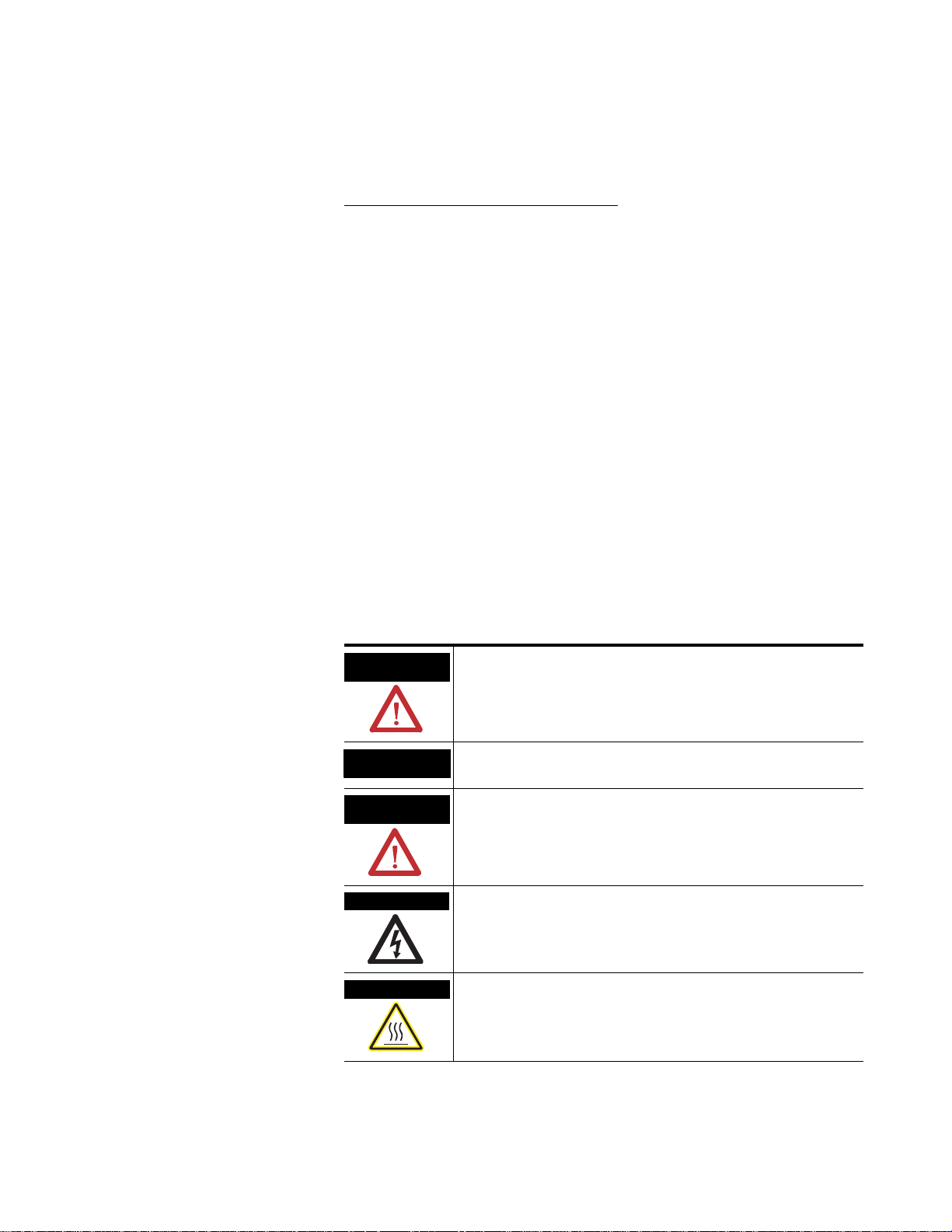
Throughout this manual, when necessary, we use notes to make you aware of
safety considerations.
WARNING
IMPORTANT
ATTENTION
Identifies information about practices or circumstances that can cause
an explosion in a hazardous environment, which may lead to personal
injury or death, property damage, or economic loss.
Identifies information that is critical for successful application and
understanding of the product.
Identifies information about practices or circumstances that can
lead to personal injury or death, property damage, or economic
loss. Attentions help you identify a hazard, avoid a hazard, and
recognize the consequence
Labels may be located on or inside the equipment, for example, a drive
or motor, to alert people that dangerous voltage may be present.
BURN HAZARD
Labels may be located on or inside the equipment, for example, a drive
or motor, to alert people that surfaces may be dangerous
temperatures.
Allen-Bradley, Compact I/O, MicroLogix 1500, RSLogix 500, CompactLogix, RSLogix 5000, RSNetWorx, and RSLinx are trademarks of
Rockwell Automation, Inc.
Trademarks not belonging to Rockwell Automation are property of their respective companies.
Page 3

Module Operation
Table of Contents
Important User Information . . . . . . . . . . . . . . . . . . . . . . . . . . . . . . . . . . 2
Preface
Who Should Use This Manual. . . . . . . . . . . . . . . . . . . . . . . . . . . . . . . . . 7
How to Use This Manual. . . . . . . . . . . . . . . . . . . . . . . . . . . . . . . . . . . . . 7
Related Documentation. . . . . . . . . . . . . . . . . . . . . . . . . . . . . . . . . . . 8
Conventions Used in This Manual . . . . . . . . . . . . . . . . . . . . . . . . . . . . . 8
Chapter 1
Overview. . . . . . . . . . . . . . . . . . . . . . . . . . . . . . . . . . . . . . . . . . . . . . . . . . 9
About the 1769-BOOLEAN Module. . . . . . . . . . . . . . . . . . . . . . . . . . 10
Module Description . . . . . . . . . . . . . . . . . . . . . . . . . . . . . . . . . . . . . . . . 11
Hardware Features. . . . . . . . . . . . . . . . . . . . . . . . . . . . . . . . . . . . . . 11
Boolean Expressions . . . . . . . . . . . . . . . . . . . . . . . . . . . . . . . . . . . . . . . 12
1769-BOOLEAN Module Block Diagram. . . . . . . . . . . . . . . . . . . . . . 13
Wire the 1769-BOOLEAN Module . . . . . . . . . . . . . . . . . . . . . . . . . . . 14
Input and Output Circuit Diagrams . . . . . . . . . . . . . . . . . . . . . . . . 14
Control Outputs Using Boolean Expressions . . . . . . . . . . . . . . . . . . . 15
Format of Boolean Expression . . . . . . . . . . . . . . . . . . . . . . . . . . . . 15
Boolean Expression Configuration Restrictions. . . . . . . . . . . . . . . . . . 15
Operands . . . . . . . . . . . . . . . . . . . . . . . . . . . . . . . . . . . . . . . . . . . . . 16
Operators . . . . . . . . . . . . . . . . . . . . . . . . . . . . . . . . . . . . . . . . . . . . . 16
Output Delay . . . . . . . . . . . . . . . . . . . . . . . . . . . . . . . . . . . . . . . . . . 17
Output Duration . . . . . . . . . . . . . . . . . . . . . . . . . . . . . . . . . . . . . . . 17
Output Delay and Duration Operation . . . . . . . . . . . . . . . . . . . . . 18
Boolean Control Mode Examples . . . . . . . . . . . . . . . . . . . . . . . . . . . . . 19
Example 1: Duration > 0, Delay > TRUE Time . . . . . . . . . . . . . . 19
Example 2: Duration > 0, Delay < TRUE Time . . . . . . . . . . . . . . 21
Example 3: Duration > 0, Delay < TRUE Time,
Retriggering Ignored. . . . . . . . . . . . . . . . . . . . . . . . . . . . . . . . . . 22
Example 4: Duration > 0, Delay = 0, Duration > TRUE Time . . 23
Example 5: Duration > 0, Delay = 0, Duration < TRUE Time . . 24
Example 6: Duration = 0, Delay < TRUE Time . . . . . . . . . . . . . . 25
Example 7: Duration = 0, Delay > TRUE Time . . . . . . . . . . . . . . 26
Chapter 2
Installation and Wiring
3 Publication 1769-RM016A-EN-P - July 2006
Overview. . . . . . . . . . . . . . . . . . . . . . . . . . . . . . . . . . . . . . . . . . . . . . . . . 27
Compliance to European Union Directives . . . . . . . . . . . . . . . . . . . . . 27
EMC Directive. . . . . . . . . . . . . . . . . . . . . . . . . . . . . . . . . . . . . . . . . 27
Low Voltage Directive. . . . . . . . . . . . . . . . . . . . . . . . . . . . . . . . . . . 28
Power Requirements . . . . . . . . . . . . . . . . . . . . . . . . . . . . . . . . . . . . . . . 28
General Considerations . . . . . . . . . . . . . . . . . . . . . . . . . . . . . . . . . . . . . 28
Hazardous Location Considerations. . . . . . . . . . . . . . . . . . . . . . . . 29
Prevent Electrostatic Discharge . . . . . . . . . . . . . . . . . . . . . . . . . . . 29
Remove Power. . . . . . . . . . . . . . . . . . . . . . . . . . . . . . . . . . . . . . . . . 30
Page 4

4
Module Data, Status, and
Configuration
Reduce Noise . . . . . . . . . . . . . . . . . . . . . . . . . . . . . . . . . . . . . . . . . . 30
Protect the Circuit Board from Contamination . . . . . . . . . . . . . . . 30
System Assembly . . . . . . . . . . . . . . . . . . . . . . . . . . . . . . . . . . . . . . . . . . 31
Mount the Module . . . . . . . . . . . . . . . . . . . . . . . . . . . . . . . . . . . . . . . . . 32
Minimum Spacing . . . . . . . . . . . . . . . . . . . . . . . . . . . . . . . . . . . . . . 32
Panel Mount. . . . . . . . . . . . . . . . . . . . . . . . . . . . . . . . . . . . . . . . . . . 33
DIN Rail Mount . . . . . . . . . . . . . . . . . . . . . . . . . . . . . . . . . . . . . . . 34
Replace a Single Module Within a System . . . . . . . . . . . . . . . . . . . . . . 34
Field Wiring Connections . . . . . . . . . . . . . . . . . . . . . . . . . . . . . . . . . . . 35
Ground. . . . . . . . . . . . . . . . . . . . . . . . . . . . . . . . . . . . . . . . . . . . . . . 35
System Wiring Guidelines . . . . . . . . . . . . . . . . . . . . . . . . . . . . . . . . 36
Label the Terminals . . . . . . . . . . . . . . . . . . . . . . . . . . . . . . . . . . . . . 36
Remove the Finger-safe Terminal Block . . . . . . . . . . . . . . . . . . . . 37
Wire the Finger-safe Terminal Block . . . . . . . . . . . . . . . . . . . . . . . 37
Wire the Module. . . . . . . . . . . . . . . . . . . . . . . . . . . . . . . . . . . . . . . . . . . 38
Input and Output Wiring . . . . . . . . . . . . . . . . . . . . . . . . . . . . . . . . 39
Chapter 3
Overview. . . . . . . . . . . . . . . . . . . . . . . . . . . . . . . . . . . . . . . . . . . . . . . . . 41
Module Inputs . . . . . . . . . . . . . . . . . . . . . . . . . . . . . . . . . . . . . . . . . 41
Module Outputs. . . . . . . . . . . . . . . . . . . . . . . . . . . . . . . . . . . . . . . . 41
1769-BOOLEAN Module Addressing . . . . . . . . . . . . . . . . . . . . . . . . . 42
1769-BOOLEAN Module Input Image. . . . . . . . . . . . . . . . . . . . . 43
1769-BOOLEAN Module Output Image . . . . . . . . . . . . . . . . . . . 43
1769-BOOLEAN Module Configuration File . . . . . . . . . . . . . . . . 43
1769-BOOLEAN Module Input Data File . . . . . . . . . . . . . . . . . . . . . 44
1769-BOOLEAN Module Output Data File . . . . . . . . . . . . . . . . . . . . 44
Direct Control of Module Outputs. . . . . . . . . . . . . . . . . . . . . . . . . 44
Virtual Inputs . . . . . . . . . . . . . . . . . . . . . . . . . . . . . . . . . . . . . . . . . . 45
1769-BOOLEAN Module Configuration Data File . . . . . . . . . . . . . . 46
Input Filtering . . . . . . . . . . . . . . . . . . . . . . . . . . . . . . . . . . . . . . . . . 47
Input Interrupts . . . . . . . . . . . . . . . . . . . . . . . . . . . . . . . . . . . . . . . . 48
Program to Fault Enable (PFE) . . . . . . . . . . . . . . . . . . . . . . . . . . . 48
Program State. . . . . . . . . . . . . . . . . . . . . . . . . . . . . . . . . . . . . . . . . . 49
Program Value . . . . . . . . . . . . . . . . . . . . . . . . . . . . . . . . . . . . . . . . . 49
Fault State. . . . . . . . . . . . . . . . . . . . . . . . . . . . . . . . . . . . . . . . . . . . . 50
Fault Value . . . . . . . . . . . . . . . . . . . . . . . . . . . . . . . . . . . . . . . . . . . . 50
Output Control (DB). . . . . . . . . . . . . . . . . . . . . . . . . . . . . . . . . . . . 51
Output Interrupts . . . . . . . . . . . . . . . . . . . . . . . . . . . . . . . . . . . . . . 51
Operands . . . . . . . . . . . . . . . . . . . . . . . . . . . . . . . . . . . . . . . . . . . . . 52
Operators . . . . . . . . . . . . . . . . . . . . . . . . . . . . . . . . . . . . . . . . . . . . . 54
Output Delay . . . . . . . . . . . . . . . . . . . . . . . . . . . . . . . . . . . . . . . . . . 55
Output Duration . . . . . . . . . . . . . . . . . . . . . . . . . . . . . . . . . . . . . . . 56
Publication 1769-RM016A-EN-P - July 2006
Page 5

Module Diagnostics and
Troubleshooting
1769-BOOLEAN Module
Specifications
5
Chapter 4
Overview. . . . . . . . . . . . . . . . . . . . . . . . . . . . . . . . . . . . . . . . . . . . . . . . . 59
Safety Considerations. . . . . . . . . . . . . . . . . . . . . . . . . . . . . . . . . . . . . . . 59
Stand Clear of the Machine . . . . . . . . . . . . . . . . . . . . . . . . . . . . . . . 59
Program Alteration . . . . . . . . . . . . . . . . . . . . . . . . . . . . . . . . . . . . . 60
Safety Circuits. . . . . . . . . . . . . . . . . . . . . . . . . . . . . . . . . . . . . . . . . . 60
Power Cycle Diagnostics . . . . . . . . . . . . . . . . . . . . . . . . . . . . . . . . . . . . 60
Module Error Definition Table . . . . . . . . . . . . . . . . . . . . . . . . . . . . . . . 60
Module Error Field . . . . . . . . . . . . . . . . . . . . . . . . . . . . . . . . . . . . . 60
Extended Error Information Field . . . . . . . . . . . . . . . . . . . . . . . . . 61
Hardware Errors . . . . . . . . . . . . . . . . . . . . . . . . . . . . . . . . . . . . . . . 61
Configuration Errors . . . . . . . . . . . . . . . . . . . . . . . . . . . . . . . . . . . . 61
Error Codes . . . . . . . . . . . . . . . . . . . . . . . . . . . . . . . . . . . . . . . . . . . 62
Module Inhibit Function . . . . . . . . . . . . . . . . . . . . . . . . . . . . . . . . . . . . 64
Contacting Rockwell Automation . . . . . . . . . . . . . . . . . . . . . . . . . . . . . 64
Appendix A
Temperature Derating . . . . . . . . . . . . . . . . . . . . . . . . . . . . . . . . . . . . . . 68
Transistor Output Transient Pulses . . . . . . . . . . . . . . . . . . . . . . . . . . . 69
Module Addressing and
Configuration with MicroLogix
1500
Configuration Using the RSLogix
5000 Generic Profile for
CompactLogix Controllers
Configure Modules in a Remote
DeviceNet System with a
1769-ADN DeviceNet Adapter
Index
Appendix B
Overview. . . . . . . . . . . . . . . . . . . . . . . . . . . . . . . . . . . . . . . . . . . . . . . . . 71
Module Addressing . . . . . . . . . . . . . . . . . . . . . . . . . . . . . . . . . . . . . . . . 72
Input Image . . . . . . . . . . . . . . . . . . . . . . . . . . . . . . . . . . . . . . . . . . . 73
Output Image. . . . . . . . . . . . . . . . . . . . . . . . . . . . . . . . . . . . . . . . . . 74
Configuration File . . . . . . . . . . . . . . . . . . . . . . . . . . . . . . . . . . . . . . 75
Configure the 1769-BOOLEAN Module in a MicroLogix 1500 System
76
Appendix C
Overview. . . . . . . . . . . . . . . . . . . . . . . . . . . . . . . . . . . . . . . . . . . . . . . . . 79
Configure the Module . . . . . . . . . . . . . . . . . . . . . . . . . . . . . . . . . . . . . . 79
Configure I/O Modules. . . . . . . . . . . . . . . . . . . . . . . . . . . . . . . . . . . . . 83
Configure the Module . . . . . . . . . . . . . . . . . . . . . . . . . . . . . . . . . . . 84
Appendix D
Overview. . . . . . . . . . . . . . . . . . . . . . . . . . . . . . . . . . . . . . . . . . . . . . . . . 85
Configuration Method . . . . . . . . . . . . . . . . . . . . . . . . . . . . . . . . . . . . . . 85
Add the DeviceNet Adapter to the Scanlist . . . . . . . . . . . . . . . . . . . . . 86
Configure the 1769-BOOLEAN Module Example . . . . . . . . . . . . . . . 88
Rockwell Automation Support . . . . . . . . . . . . . . . . . . . . . . . . . . . . . . . 96
Installation Assistance . . . . . . . . . . . . . . . . . . . . . . . . . . . . . . . . . . . 96
New Product Satisfaction Return . . . . . . . . . . . . . . . . . . . . . . . . . . 96
Publication 1769-RM016A-EN-P - July 2006
Page 6

6
Notes:
Publication 1769-RM016A-EN-P - July 2006
Page 7

Preface
Read this preface to familiarize yourself with the rest of the manual. This
preface covers the following topics:
• Who should use this manual
• How to use this manual
• Related publications
• Conventions used in this manual
Who Should Use This Manual
How to Use This Manual
Use this manual if you are responsible for designing, installing, programming,
or troubleshooting control systems that use the Allen-Bradley Compact I/O
system.
As much as possible, we organized this manual to explain, in a task-by-task
manner, how to install, configure, program, operate, and troubleshoot a
control system using the 1769 BOOLEAN module.
7 Publication 1769-RM016A-EN-P - July 2006
Page 8

8
Related Documentation
The table below provides a listing of publications that contain important
information about using Compact I/O modules.
For Read this document Document number
A user manual containing information on how to install,
use and program your MicroLogix 1500 controller.
A user manual containing information on how to install,
and use your 1769-ADN DeviceNet adapter.
A user manual containing information on how to install,
use and program your 1769-L20 and 1769-L30
CompactLogix controllers.
A user manual containing information on how to install,
use and program your 1769-L31, 1769-L32C, 1769-L32E,
1769-L35CR and 1769-L35E CompactLogix controllers.
An overview of 1769 Compact I/O modules. Compact I/O System Selection Guide 1769-SG002
In-depth information on grounding and wiring
Allen-Bradley programmable controllers.
MicroLogix 1500 User Manual 1764-UM001
DeviceNet Adapter User Manual 1769-UM001
CompactLogix User Manual 1769-UM007
CompactLogix System User Manual 1769-UM011
Allen-Bradley Programmable Controller Grounding and
Wiring Guidelines
1770-4.1
If you would like a manual, you can:
• download a free electronic version from the Internet at
http://literature.rockwellautomation.com
• purchase a printed manual by contacting your local distributor or
Rockwell Automation representative.
Conventions Used in This Manual
Publication 1769-RM016A-EN-P - July 2006
We use the following conventions throughout this manual.
• Bulleted lists (like this one) provide information, not procedural steps.
• Numbered lists provide sequential steps or hierarchical information.
• Bold type is used for emphasis.
Page 9

Module Operation
Chapter
1
Overview
This chapter contains information about the following.
• Module description
• Module block diagram
• Input and output circuit diagrams
• Controlling outputs using Boolean expressions
– Format of Boolean expression
– Allowed variations of Boolean expressions
– Operands
– Operators
– Output delay control
– Output duration control
– Delay/Duration control rules and examples
Topic Page
About the 1769-BOOLEAN Module 1
Module Description 11
Boolean Expressions 12
1769-BOOLEAN Module Block Diagram 13
Wire the 1769-BOOLEAN Module 14
Control Outputs Using Boolean Expressions 15
Boolean Expression Configuration Restrictions 15
Boolean Control Mode Examples 19
9 Publication 1769-RM016A-EN-P - July 2006
Page 10

10 Module Operation
About the 1769-BOOLEAN Module
The 1769-BOOLEAN module is a 24V dc combination input/output module.
The module outputs can be either directly controlled from your program or
independently controlled by the module using configured Boolean
expressions. These Boolean expressions are simple, logical combinations of
the module hardware input states and soft inputs controlled by your program.
When controlled by Boolean expression, the 1769-BOOLEAN module output
states can be conditioned using configured delay and duration settings. The
1769-BOOLEAN module supports interrupts to the system controller on
both input and output change of states
(1)
.
The Compact I/O system is suitable for use in an industrial environment
when installed in accordance with these instructions. Specifically, this
equipment is intended for use in clean, dry environments (Pollution degree
(2)
) and to circuits not exceeding Over Voltage Category II
2
(4)
60664-1)
.
(3)
(IEC
Publication 1769-RM016A-EN-P - July 2006
(1)
Interrupts from the module to the controller may not be supported by all controllers. Refer to your controller's
user manual for more information.
(2)
Pollution Degree 2 is an environment where, normally, only nonconductive pollution occurs except that occasionally a
temporary conductivity caused by condensation is expected.
(3)
Over Voltage Category II is the load-level section of the electrical distribution system. At this level, transient voltages are
controlled and do not exceed the impulse voltage capability of the product’s insulation.
(4)
Pollution Degree 2 and Over Voltage Category II are International Electrotechnical Commission (IEC) designations.
Page 11
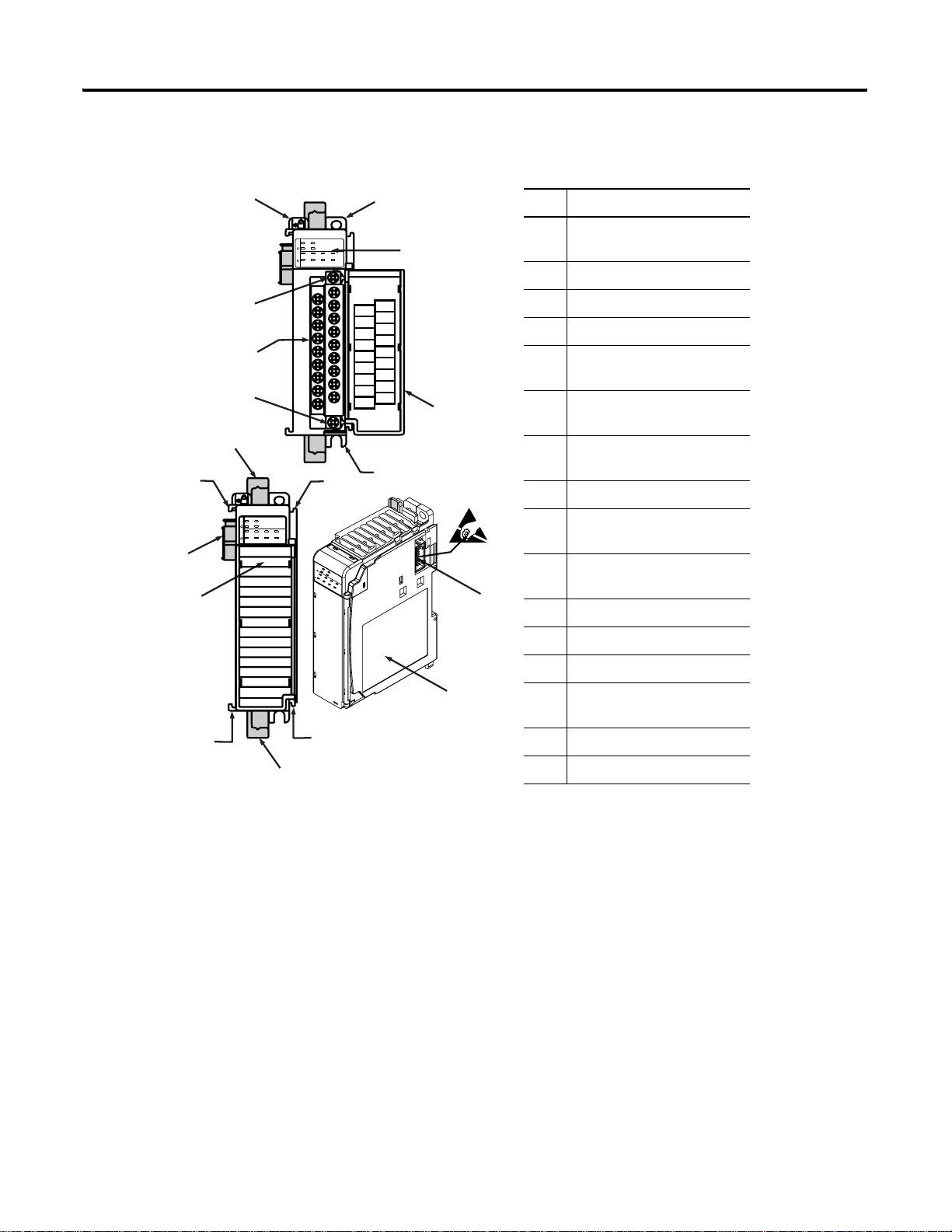
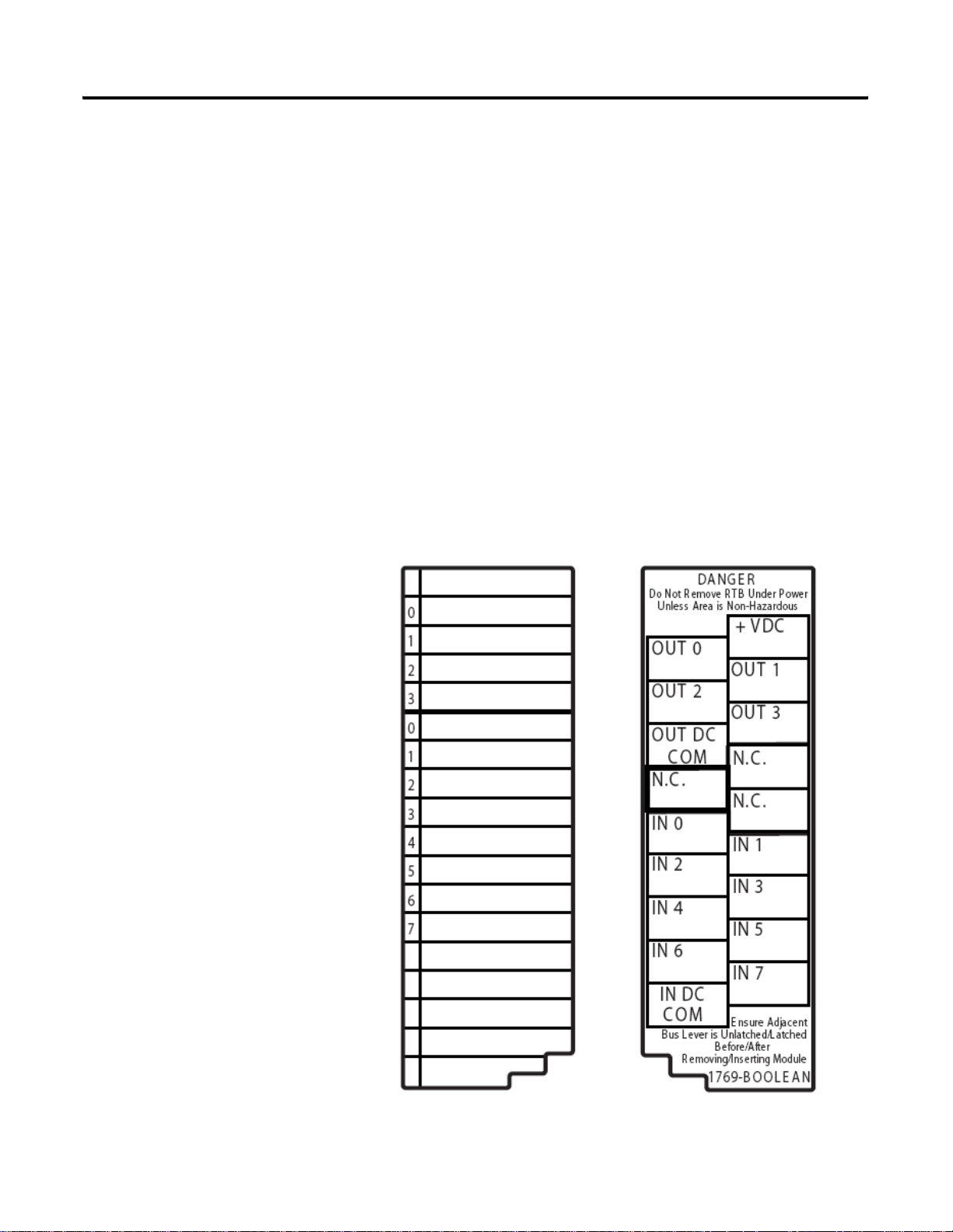
Module Description
1
5
b
Module Operation 11
7a
10a
10b
8a
10
0
2
1
3
0246
IN OUT
BOOLEAN
7531
7a
2a
DANGER
Do Not Remove RTB Under Power
Unless Area is Non-Hazardous
+VDC
OUT 0
OUT 1
OUT 2
OUT 3
OUT DC
COM
N.C.
N.C.
N.C.
IN 0
IN 1
IN 2
IN 3
IN 4
IN 5
IN 6
IN 7
IN DC
COM
Ensure Adjacent
Bus Lever is Unlatched/Latched
Before/After
Removing/Inserting Module
1769-BOOLEAN
2b
3
4
Item Description
1 Bus lever (with locking
function)
2a Upper panel mounting tab
2b Lower panel mounting tab
3 Module status LED
4 Module door with terminal
identification label
5a Movable bus connector
with female pins
5b Stationary bus connector
with male pins
6 Nameplate label
0
2
1
3
0246
IN OUT
7531
BOOLEAN
a
9
0
1
2
3
0
1
2
3
4
5
6
7
0
1
2
3
0
IN OUT
2
1
46
3
Boolean
5
7
7a Upper
tongue-and-groove slots
7b Lower
tongue-and-groove slots
5
8a Upper DIN rail latch
8b Lower DIN rail latch
9 Write-on label (user ID tag)
6
10 Removable terminal block (RTB)
with finger-safe cover
7b
7b
8b
10a RTB upper retaining screw
10b RTB lower retaining screw
Hardware Features
The 1769-BOOLEAN module contains a removable terminal block. The
module input circuits are isolated from the output circuits. Single-ground
applications can be supported by wiring the IN DC COM and the OUT DC
COM terminals together; however, this eliminates the isolation between the
input and output circuits provided by the module.
Module configuration is normally done via the controller programming
software. In addition, some controllers support configuration via the user
program. In either case, the controller memory stores the module
configuration. Refer to your controller's user manual for more information.
Publication 1769-RM016A-EN-P - July 2006
Page 12

12 Module Operation
Boolean Expressions
An expression is any legal combination of symbols that represents a value. An
expression that results in a value of either TRUE or FALSE is called a Boolean
expression. Every Boolean expression (except a null expression) consists of at
least one operand and can have one or more operators. Operands are values,
whereas operators are symbols that represent particular logical actions. For
example, in the expression
OUT = A AND B,
the value of OUT is either TRUE or FALSE and is determined by the value of
the expression “A AND B”. A and B are operands that also have a value of
TRUE or FALSE. The operator in the expression is the logical operator AND.
Other examples of logical operators are OR and XOR (exclusive-OR).
The 1769-BOOLEAN module outputs can be controlled based upon the
value of Boolean expressions configured by the program. An output state
(when in Boolean control mode) is determined by the state of that output’s
configured Boolean expression, with a value of TRUE corresponding to the
ON state and a value of FALSE corresponding to the OFF state.
Refer to Chapter 3, Module Data, Status, and Configuration on page 41, for
information on configuring control of the 1769-BOOLEAN module outputs
using Boolean expressions.
Publication 1769-RM016A-EN-P - July 2006
Page 13
Module Operation 13
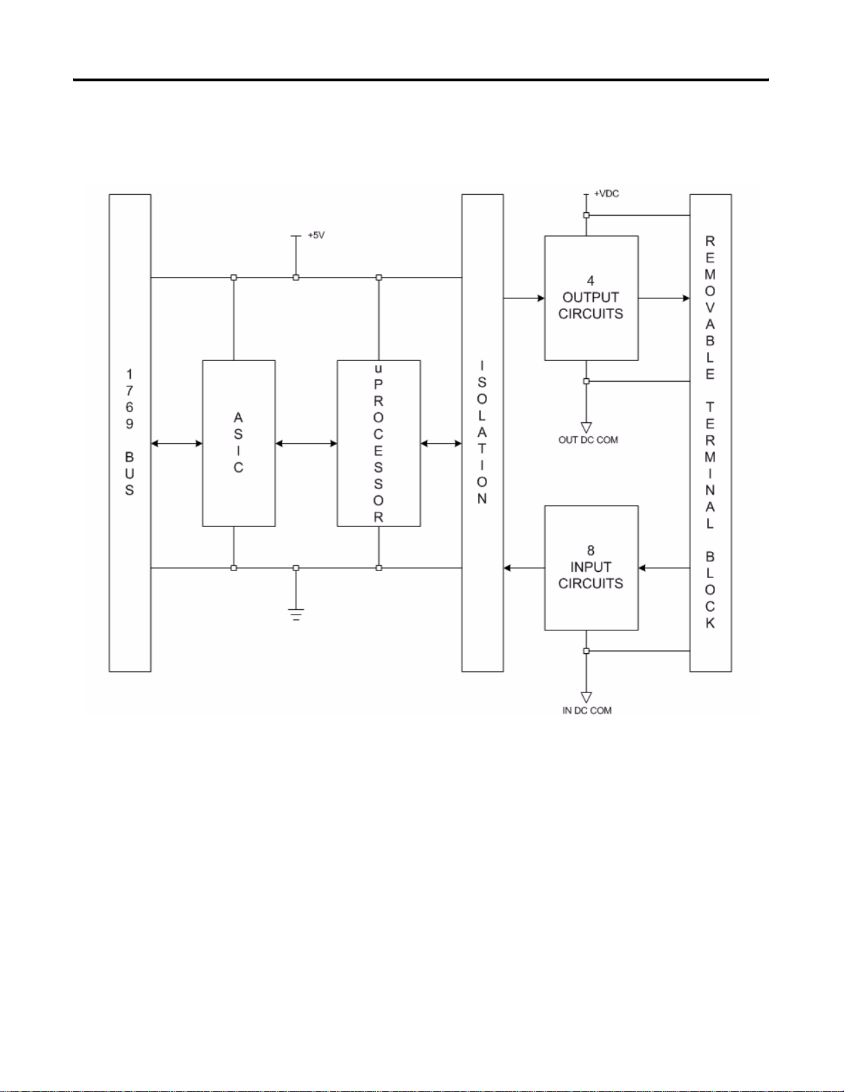
1769-BOOLEAN Module Block Diagram
The following figure is the block diagram for the 1769-BOOLEAN module.
1769-BOOLEAN Module Block Diagram
Publication 1769-RM016A-EN-P - July 2006
Page 14
14 Module Operation
Wire the 1769-BOOLEAN Module
Each terminal accepts as many as two wires with these restrictions.
Wire Type Wire Size Terminal
Screw Torque
Solid Cu-90 °C (194 °F) 2.08…0.34 mm
(14…22 AWG)
Stranded Cu-90 °C (194 °F) 1.31…0.34 mm
(16…22 AWG)
2
0.68 Nm (6 lb-in) 0.46 Nm (4.1
2
0.68 Nm (6 lb-in) 0.46 Nm (4.1
Retaining
Screw Torque
lb-in)
lb-in)
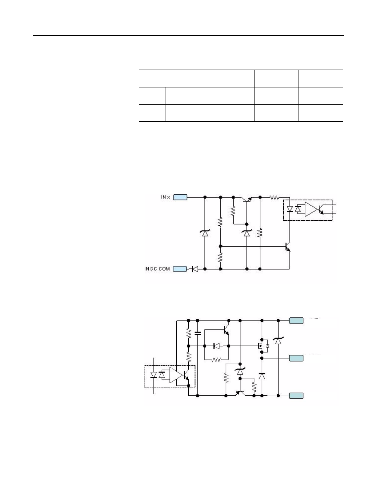
Input and Output Circuit Diagrams
The following figures illustrate the simplified input and output circuits.
Simplified Input Circuit Diagram
Publication 1769-RM016A-EN-P - July 2006
Simplified Output Circuit Diagram
+VDC
OUT x
OUT DC COM
Page 15

Module Operation 15
Control Outputs Using Boolean Expressions
You can configure the 1769-BOOLEAN module outputs to be controlled by
Boolean expression (Boolean control mode).
Format of Boolean Expression
Each output is controlled with a separate expression. The fixed format of each
Boolean expression is assumed to be of the form:
Output State = (A x B) y C
where A, B, and C are operands and x and y are logical operators you select.
The location of the parentheses in the fixed format indicates that the logical
operation represented by x is performed on operands A and B first, with the
result of that operation then used as the first operand for the logical operation
represented by y (with C being the second operand).
The parameter names assigned in the 1769-BOOLEAN module configuration
file that correspond to the operands and operators of the fixed format
Boolean expression above are:
A: Operand_A_#
Boolean Expression Configuration Restrictions
B: Operand_B_#
C: Operand_C_#
x: Operator_1_#
y: Operator_2_#
where the # symbol indicates the module output (OUT0 through OUT3).
The Boolean expressions controlling the output states have default values
assigned to each operand and operator. These default values assign “None” to
each operand and operator resulting in a “Null” expression. A “Null”
expression will be accepted by the module but will result in an output that will
always be in the OFF state.
The module will only accept the following variations of Boolean expressions
as valid (based on the fixed format expression (A x B) y C).
Publication 1769-RM016A-EN-P - July 2006
Page 16

16 Module Operation
Variations of Boolean Expressions
Variation Description
Null All operands and operators assigned a value of “None”.
A Only the first operand assigned a non-default value, all other
operands and all operators assigned a value of “None”.
A x B Only the first two operands and the first operator assigned a
non-default value, final operand and final operator assigned
a value of “None”
(A x B) y C All operands and operators assigned non-default values)
Operands
The operands in each output's Boolean expression can be configured to be
one of the following.
• None (default)
• Current state of one of the module's eight, real inputs
• Inverted, current state of one of the module's eight, real inputs
• Current state of one of the module's eight, virtual inputs (controlled by
the user program via the module's output data file)
• Inverted, current state of one of the module's eight, virtual inputs
Refer to Chapter 3, Module Data, Status, and Configuration on page 41, for
details on configuring the Boolean expression operands.
Operators
The operators in each output Boolean expression can be configured to be one
of the following (the operator's effect on a pair of operands is described).
Boolean Expression and the Related Operator Effect
Expression Operator Effect
None Default, no logical operation performed.
OR If either operand in TRUE, the result is TRUE.
AND Both operands must be TRUE for the result to be TRUE.
Publication 1769-RM016A-EN-P - July 2006
XOR Exclusive - OR, one operand must be TRUE and the other
FALSE for the result to be TRUE.
Refer to Chapter 3, Module Data, Status, and Configuration on page 41, for
details on configuring the Boolean expression operators.
Page 17

Module Operation 17
Output Delay
When configured for Boolean control, the module's outputs are directed ON
when the Boolean expression for each output channel is TRUE. The module
can be configured to add a delay between an output's Boolean expression
becoming TRUE and the output being placed into the ON state. The length of
this delay time for an output operating in Boolean control mode can be
configured to be between 0 (default) and 1 second in 1 ms increments.
Refer to Chapter 3, Module Data, Status, and Configuration on page 41, for
details on configuring the Boolean expression output delay.
Output Duration
When configured for Boolean control, if an output is directed ON as the result
of the output's Boolean expression becoming TRUE, and the Output Delay
time for that output has been satisfied, then the length of time an output stays
ON can be controlled by designating an Output Duration. The length of this
duration time for an output operating in Boolean control mode can be
configured to be either a fixed amount of time between 1 ms and 1 second (in
1 ms increments), or, the output can be configured to remain ON only as long
as its Boolean expression remains TRUE (duration time set to 0, this is the
default setting).
Refer to Chapter 3, Module Data, Status, and Configuration on page 41, for
details on configuring the Boolean expression output duration.
Publication 1769-RM016A-EN-P - July 2006
Page 18

18 Module Operation
Output Delay and Duration Operation
Since an output's Boolean expression can change in real time, configuring a
delay and/or duration time when an output is in Boolean control mode could
cause confusion.
The module shall operate in the following manner when output delay and/or
duration times are configured to non-default values (while an output is
configured for Boolean control).
When the Boolean expression controlling an output transitions from FALSE
to TRUE, the output will be directed ON after the delay time has expired only
if:
Case 1
• The output's duration time is not equal to 0. In this case the output
should be directed ON for the length of the duration time regardless of
the state of the output's Boolean expression and then should be directed
OFF regardless of the state of the Boolean expression.
• In Case 1 a “One-shot” type of function has been configured. The
output will be turned ON with a single pulse of configured delay time
and duration time when the output's Boolean expression becomes
TRUE. The length of time the Boolean expression remains TRUE does
not determine whether the “One-shot” pulse occurs. As long as the
duration time of the output has been configured to a value greater than
0, then a “One-shot” ON pulse will occur and the output will remain
ON for the length of the duration time. The output will then turn OFF
regardless of the state of the output's Boolean expression.
• Retriggering of the output is not supported. Any additional transitions
of the output's Boolean expression from FALSE to TRUE after the
initial transition to TRUE are ignored for a length of time equal to the
configured delay time added to the configured duration time. Once the
output's “One-shot” pulse duration is complete, and the output is
turned OFF, a FALSE to TRUE transition of the Boolean expression
will cause another “One-shot” ON pulse to occur.
Case 2
• The output's duration is equal to 0 and the output's Boolean expression
has maintained a state of TRUE for the entire delay time. The output
should then be directed OFF when the output's Boolean expression
becomes FALSE.
Publication 1769-RM016A-EN-P - July 2006
Page 19

Module Operation 19
• In Case 2 the output will follow the state of the Boolean expression as
long as the configured delay time has expired and the Boolean
expression has maintained a TRUE state. When an output's Boolean
expression transitions from FALSE to TRUE, the output will be turned
ON only if the Boolean expression has maintained a state of TRUE for
the entire length of the delay time. If the output's Boolean expression
transitions to FALSE before the configured delay time expires, then the
delay time should be terminated and the output should not be turned
ON. If the output's Boolean expression has maintained a TRUE state
for the full length of the delay time, the output will be turned ON and
will remain ON until the Boolean expression becomes FALSE.
• If an output's Boolean expression is configured with both the delay and
duration times set to 0, then the output simply follows the state of the
Boolean expression, ON when the expression is TRUE and OFF when
it is FALSE.
Boolean Control Mode Examples
The following examples illustrate the module's operation when an output is
configured in Boolean control mode. Examples 1…5 show module output
operation for Case 1 where the configured duration time is greater than 0.
Examples 6 and 7 show module operation for Case 2 where the configured
duration time is equal to 0.
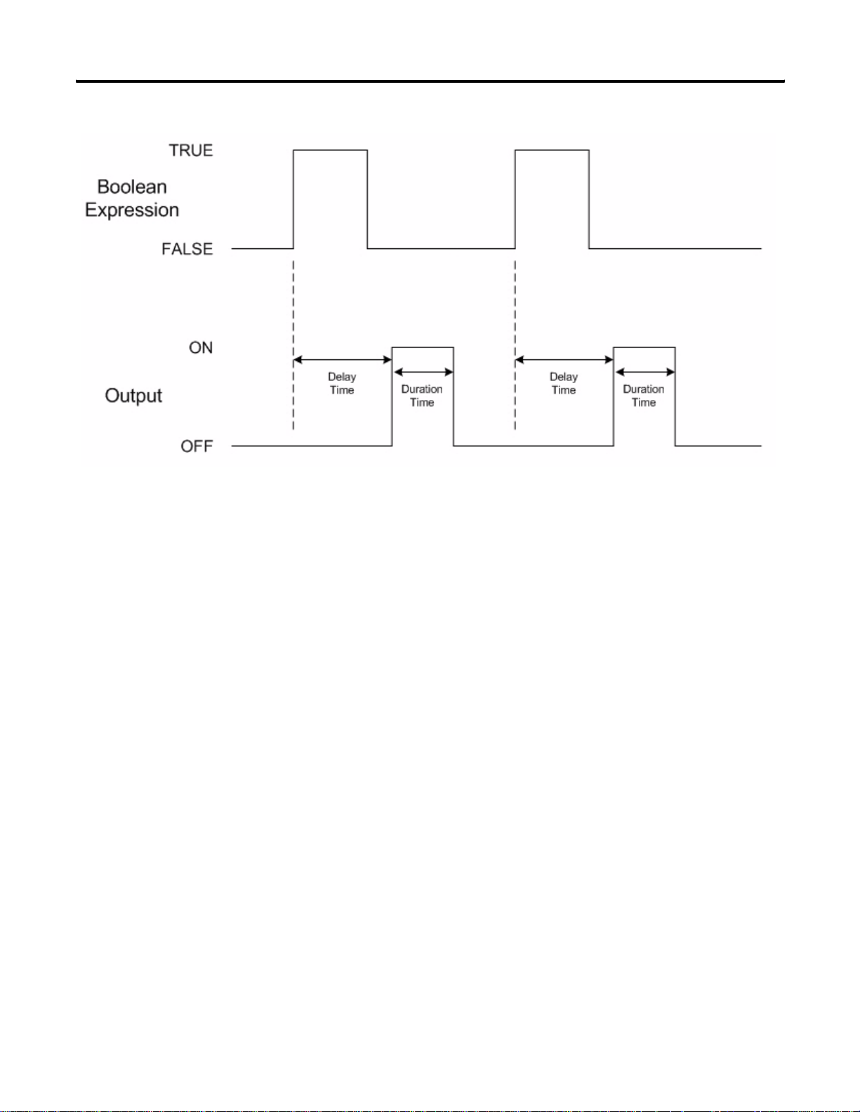
Example 1: Duration > 0, Delay > TRUE Time
In this example, the output is configured with a duration time greater than 0, a
delay time greater than 0, and the configured delay time is longer than the time
that the Boolean expression remains TRUE.
Since the configured duration time is greater than 0, a “One-shot” pulse
occurs on the output. The pulse starts an amount of time after the FALSE to
TRUE transition of the Boolean expression equal to the configured delay time.
The “One-shot” pulse lasts as long as the configured duration time even
though the Boolean expression transitions to FALSE. The second “One-shot”
pulse occurs on the output since there was a FALSE to TRUE transition in the
Boolean expression after the first “One-shot” pulse is completed.
Publication 1769-RM016A-EN-P - July 2006
Page 20
20 Module Operation
Publication 1769-RM016A-EN-P - July 2006
Page 21
Module Operation 21
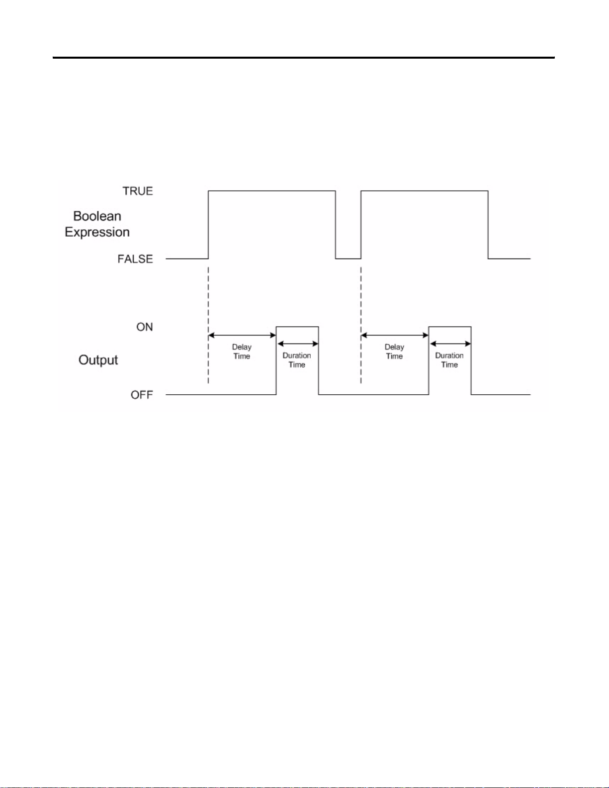
Example 2: Duration > 0, Delay < TRUE Time
In this example, the output is configured with a duration time greater than 0, a
delay time greater than 0, and the configured delay time is shorter than the
time that the Boolean expression remains TRUE.
Again, since the configured duration time is greater than 0, a “One-shot” pulse
occurs on the output. The pulse starts an amount of time after the FALSE to
TRUE transition of the Boolean expression equal to the configured delay time.
The “One-shot” pulse again lasts only as long as the configured duration time
even though the Boolean expression remains TRUE. The second “One-shot”
pulse occurs on the output since there was a FALSE to TRUE transition in the
Boolean expression after the first “One-shot” pulse is completed.
Publication 1769-RM016A-EN-P - July 2006
Page 22
22 Module Operation
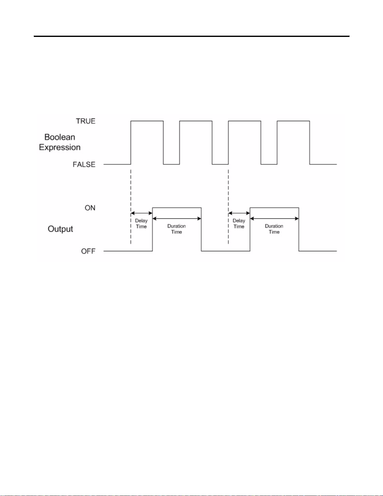
Example 3: Duration > 0, Delay < TRUE Time, Retriggering Ignored
In this example, the output is configured with a duration time greater than 0, a
delay time greater than 0, and multiple transitions of the Boolean expression
occur before the initial “One-shot” pulse duration is completed.
The first FALSE to TRUE transition of the Boolean expression causes a
“One-shot” pulse to occur. The pulse starts an amount of time after the
FALSE to TRUE transition of the Boolean expression equal to the configured
delay time. The “One-shot” pulse lasts as long as the configured duration time.
Since the second FALSE to TRUE transition of the Boolean expression occurs
before the initial “One-shot” pulse is completed, that transition of the Boolean
expression is ignored by the module. The third FALSE to TRUE transition of
the Boolean expression again causes a “One-shot” pulse, with the fourth
FALSE to TRUE transition of the Boolean expression again ignored by the
module since it occurs before the second “One-shot” pulse is complete.
Publication 1769-RM016A-EN-P - July 2006
Page 23
Module Operation 23
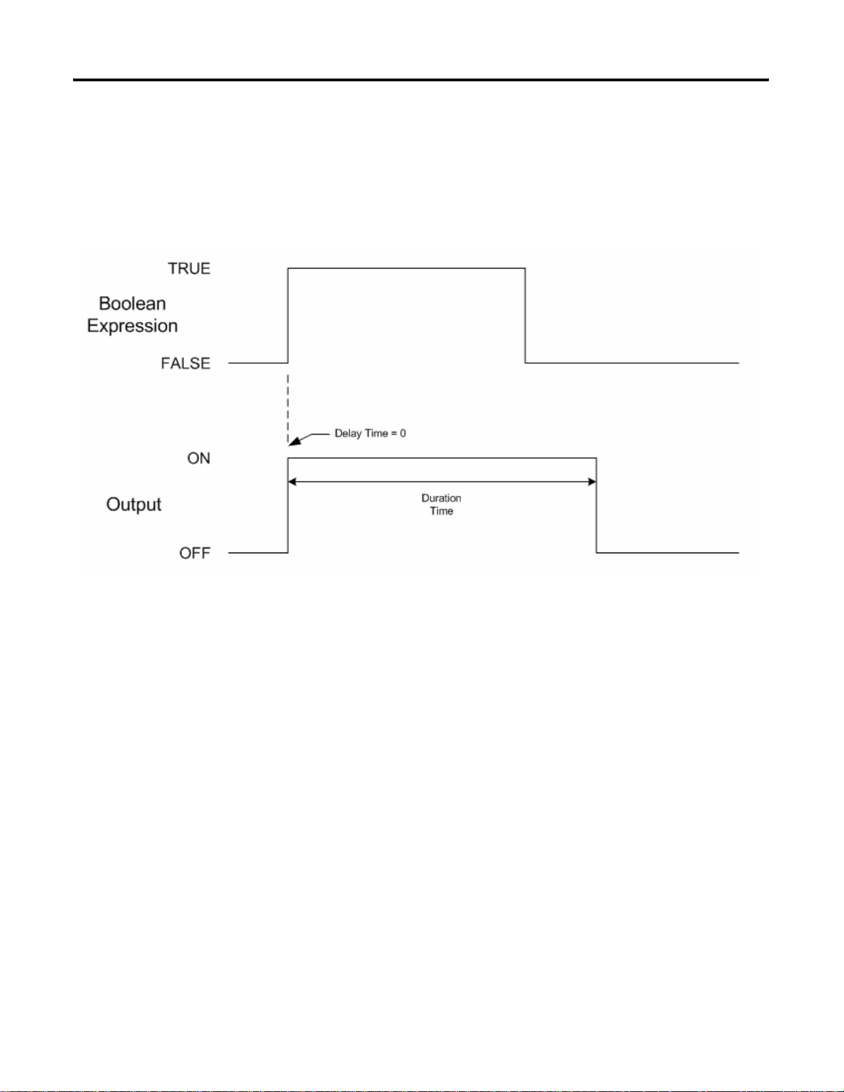
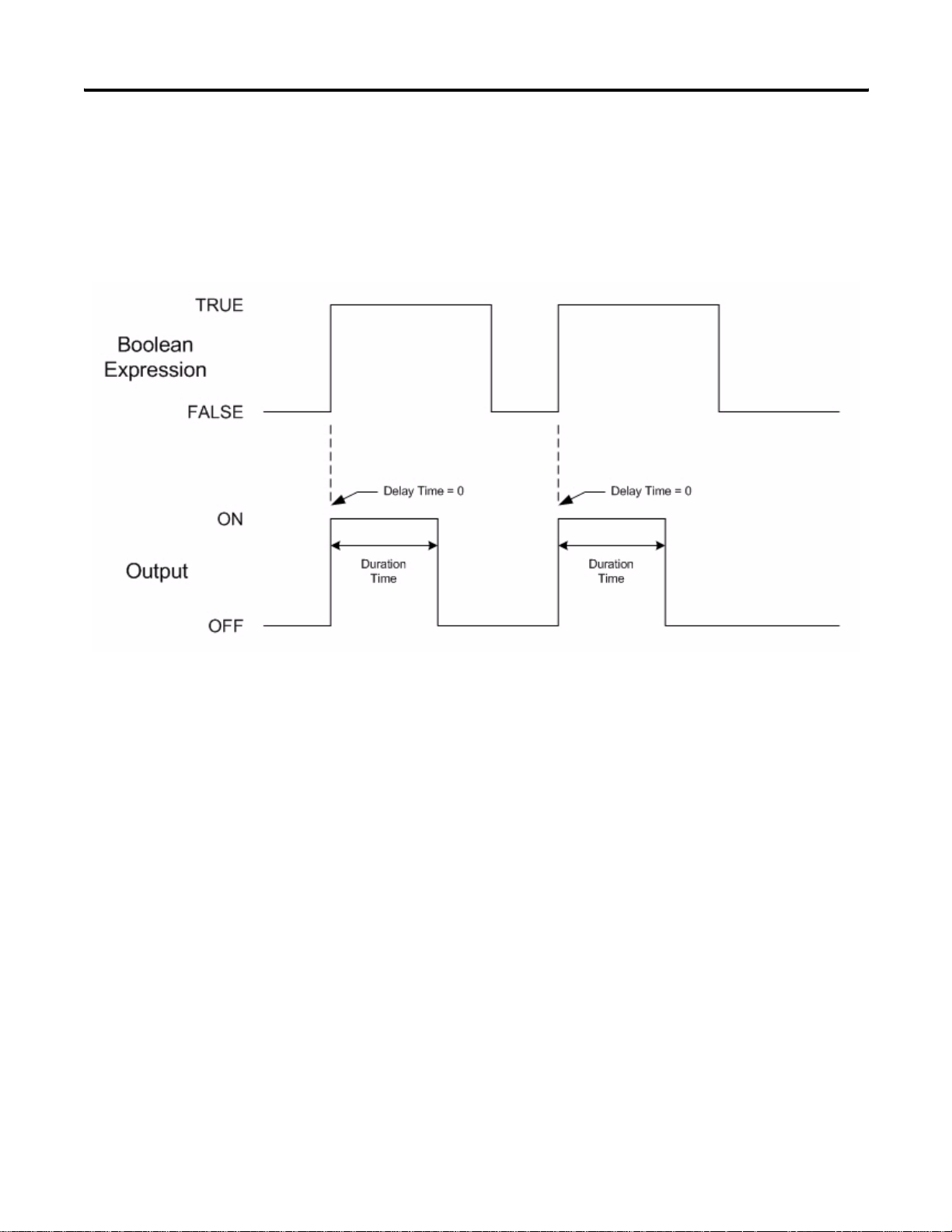
Example 4: Duration > 0, Delay = 0, Duration > TRUE Time
In this example, the output is configured with a duration time greater than 0, a
delay time equal to 0, and the configured duration time is longer than the time
that the Boolean expression remains TRUE.
Since the configured duration time is greater than 0, a “One-shot” pulse
occurs on the output. The pulse starts at the same time as the FALSE to
TRUE transition of the Boolean expression because the configured delay time
is equal to 0. The “One-shot” pulse lasts as long as the configured duration
time even though the Boolean expression transitions to FALSE.
Publication 1769-RM016A-EN-P - July 2006
Page 24
24 Module Operation
Example 5: Duration > 0, Delay = 0, Duration < TRUE Time
In this example, the output is configured with a duration time greater than 0, a
delay time equal to 0, and the configured duration time is shorter than the time
that the Boolean expression remains TRUE.
Again, since the configured duration time is greater than 0, a “One-shot” pulse
occurs on the output. The pulse starts at the same time as the FALSE to
TRUE transition of the Boolean expression because the configured delay time
is equal to 0. The “One-shot” pulse again lasts only as long as the configured
duration time even though the Boolean expression remains TRUE. The
second “One-shot” pulse occurs on the output since there was a FALSE to
TRUE transition in the Boolean expression after the first “One-shot” pulse is
completed.
Publication 1769-RM016A-EN-P - July 2006
Page 25
Module Operation 25
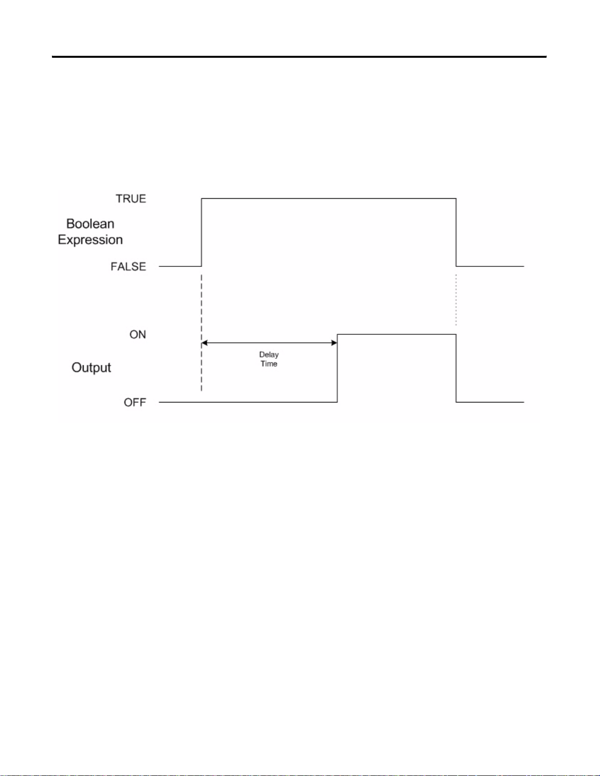
Example 6: Duration = 0, Delay < TRUE Time
In this example, the output is configured with a duration time equal to 0 (the
output will remain ON only if the Boolean expression remains TRUE), a delay
time greater than 0, and the Boolean expression continuously remains TRUE
for a length of time greater than the configured delay time.
Since the delay time is greater than 0, the output does not turn ON until the
Boolean expression has maintained a TRUE condition for a period of time
equal to the configured delay time. The output remains ON until the Boolean
expression becomes FALSE. The output immediately turns OFF since the
configured duration time is 0.
Publication 1769-RM016A-EN-P - July 2006
Page 26
26 Module Operation
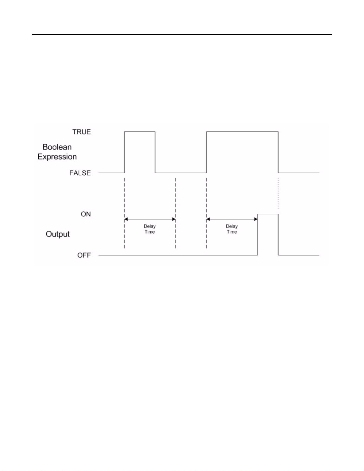
Example 7: Duration = 0, Delay > TRUE Ti me
In this example, the output is configured with a duration time equal to 0 (the
output will remain ON only if the Boolean expression remains TRUE) and a
delay time greater than 0. Conditions where the Boolean expression remains
TRUE both for less than and longer than the configured delay time are
illustrated.
Publication 1769-RM016A-EN-P - July 2006
The first instance that the Boolean expression goes to the TRUE state, but
does not remain continuously TRUE for a period of time exceeding the
configured delay time, it does not cause the output to turn ON. When this first
TRUE condition ends, the corresponding delay time event also ends. The next
time the Boolean expression becomes TRUE, a new delay time event begins.
This second TRUE event does continuously remain TRUE for longer than the
configured delay time and the output turns ON. The output remains ON until
the Boolean expression becomes FALSE, at which point it immediately turns
OFF since the configured duration time is 0.
Page 27

Installation and Wiring
Chapter
2
Overview
This chapter tells you how to:
• determine the power requirements for the module.
• avoid electrostatic damage.
• install the module.
• wire the module’s terminal block.
• wire input devices.
• wire output devices.
Topic Page
Compliance to European Union Directives 27 Power Requirements 28 General Considerations 28 System Assembly 31 Mount the Module 32 Replace a Single Module Within a System 34 Field Wiring Connections 35 Wire the Module 38
Compliance to European
This product is approved for installation within the European Union and EEA
regions. It has been designed and tested to meet the following directives.
Union Directives
EMC Directive
The analog modules are tested to meet Council Directive 89/336/EEC
Electromagnetic Compatibility (EMC) and the following standards, in whole
or in part, documented in a technical construction file:
• EN 61000-6-4:2001
Electromagnetic Compatibility (EMC) - Part 6-4: Generic Standards Emission Standard for Industrial Environments
• EN 61000-6-2:2001
Electromagnetic Compatibility (EMC) - Part 6-4: Generic Standards Immunity for Industrial Environments
This product is intended for use in an industrial environment.
27 Publication 1769-RM016A-EN-P - July 2006
Page 28

28 Installation and Wiring
Low Voltage Directive
This product is tested to meet Council Directive 73/23/EEC Low Voltage, by
applying the safety requirements of EN 61131-2 Programmable Controllers,
Part 2 – Equipment Requirements and Tests.
For specific information required by EN61131-2, see the appropriate sections
in this publication, as well as the following Allen-Bradley publications:
• Industrial Automation Wiring and Grounding Guidelines for Noise
Immunity, publication 1770-4.1
• Automation Systems Catalog, publication B113
Power Requirements
General Considerations
The module receives power through the bus interface from the +5V dc/+24V
dc system power supply. The maximum current draw for the
1769-BOOLEAN module is:
• 5V dc: 220 mA.
• 24V dc: 0 mA.
The Compact I/O system is suitable for use in an industrial environment
when installed in accordance with these instructions. Specifically, this
equipment is intended for use in clean, dry environments (Pollution degree
(1)
) and to circuits not exceeding Over Voltage Category II
2
60664-1).
(3)
(2)
(IEC
Publication 1769-RM016A-EN-P - July 2006
(1)
Pollution Degree 2 is an environment where, normally, only nonconductive pollution occurs except that
occasionally a temporary conductivity caused by condensation shall be expected.
(2)
Over Voltage Category II is the load level section of the electrical distribution system. At this level transient
voltages are controlled and do not exceed the impulse voltage capability of the product’ s insulation.
(3)
Pollution Degree 2 and Over Voltage Category II are International Electrotechnical Commission (IEC)
designations.
Page 29
Installation and Wiring 29
Hazardous Location Considerations
This equipment is suitable for use in Class I, Division 2, Groups A, B, C, D or
nonhazardous locations only. The following attention statement applies to use
in hazardous locations.
ATTENTION
Explosion Hazard
• Substitution of components may impair suitability for Class I,
Division 2.
• Do not replace components or disconnect eq uipment unless
power has been switched off or the area is known to be
nonhazardous.
• Do not connect or disconnect components unless power has
been switched off or the area is known to be nonhazardous.
• This product must be installed in an enclosure.
• All wiring must comply with N.E.C. article 501-4(b).
Prevent Electrostatic Discharge
ATTENTION
Electrostatic discharge can damage integrated circuits or
semiconductors if you touch th e bus connector pins or the
terminal block on the module. Follow these guidelines when
you handle the module:
• Touch a grounded object to discharge static potential.
• Wear an approved wrist-strap grounding device.
• Do not touch the bus connector or connector pins.
• Do not touch circuit components inside the module.
• Use a static-safe work station, if available.
• Keep the module in its static-shield box when it is not in
use.
Publication 1769-RM016A-EN-P - July 2006
Page 30

30 Installation and Wiring
Remove Power
ATTENTION
Remove power before removing or inserting this module. When
you remove or insert a module with power applied, an electrical
arc may occur. An electrical arc can cause personal injury or
property damage by:
• sending an erroneous signal to your system’s field devices,
causing unintended machine motion.
• causing an explosion in a hazardous environment.
Electrical arcing causes excessive wear to contacts on both the
module and its mating connector and may lead to premature
failure.
Reduce Noise
Most applications require installation in an industrial enclosure to reduce the
effects of electrical interference. Group your modules to minimize adverse
effects from radiated electrical noise and heat. Consider the following
conditions when selecting a location for the module. Position the module:
• away from sources of electrical noise such as hard-contact switches,
relays, and ac motor drives.
• away from modules that generate significant radiated heat, such as the
1769-IA16 module. Refer to the module’s heat dissipation specification.
Publication 1769-RM016A-EN-P - July 2006
Protect the Circuit Board from Contamination
The printed circuit board of the module must be protected from dirt, oil,
moisture, and other airborne contaminants. To protect the printed circuit
board, the system must be installed in an enclosure suitable for the
environment. The interior of the enclosure should be kept clean and the
enclosure door should be kept closed whenever possible.
Page 31

Installation and Wiring 31
System Assembly
2
The module can be attached to the controller or an adjacent I/O module
before or after mounting.
Refer to Panel Mounting Using the Dimensional Template on page 33, for
mounting instructions, or to DIN Rail Mount on page 34.
Refer to Replace a Single Module Within a System on page 34, for information
on working with a system that is already mounted.
3
4
1
6
1
5
1. Disconnect power.
2. Check that the bus lever of the module to be installed is in the unlocked
(fully right) position.
3. Use the upper and lower tongue-and-groove slots (1) to secure the
modules together (or to a controller).
4. Move the module back along the tongue-and-groove slots until the bus
connectors (2) line up with each other.
5. Push the bus lever back slightly to clear the positioning tab (3), using
your fingers or a small screwdriver.
Publication 1769-RM016A-EN-P - July 2006
Page 32

32 Installation and Wiring
6. Move the bus lever fully to the left (4) until it clicks, making sure it is
locked firmly in place, to allow communication between the controller
and module.
Mount the Module
ATTENTION
When attaching I/O modules, it is very important that
the bus connectors are securely locked together to be
sure of proper electrical connection.
7. Attach an end cap terminator (5) to the last module in the system by
using the tongue-and-groove slots as before.
8. Lock the end cap bus terminator (6).
IMPORTANT
A 1769-ECR or 1769-ECL right or left end cap must be used to
terminate the end of the bus.
ATTENTION
During panel or DIN rail mounting of all devices, be sure that all
debris (that is, metal chips or wire strands) is kept from falling
into the module. Debris that falls into the module could cause
damage when you cycle power.
Publication 1769-RM016A-EN-P - July 2006
Minimum Spacing
Maintain spacing from enclosure walls, wireways, or adjacent equipment.
Allow 50 mm (2 in.) of space on all sides for adequate ventilation.
Space Requirements
Top
Side
Host Controller
Compact I/O
Bottom
Compact I/O
Compact I/O
Compact I/O
Compact I/O
Side
End Cap
Page 33

Installation and Wiring 33
Panel Mount
Mount the module to a panel using two screws per module. Use M4 or #8
panhead screws. Mounting screws are required on every module.
Panel Mounting Using the Dimensional Template
Spacing for one-and-a-half-wide modules 52.5 mm (2.067 in.).
Refer to the host controller documentation for this dimension.
Overall hole spacing tolerance:
±0.4 mm (0.016 in.).
Spacing for single-wide modules 35 mm (1.378 in.).
l Mounting
Locate holes every 17.5 mm (0.689 in.) to allow for a
mix of single-wide and one-and-a-half-wide modules
(for example, the 1769-OA16 module).
Host Controller
Panel Mounting Procedure Using Modules as a Template
This procedure lets you use the assembled modules as a template for drilling
holes in the panel. If you have sophisticated panel-mounting equipment, you
can use the dimensional template provided. Due to module mounting hole
tolerance, it is important to follow these procedures.
1. Assemble no more than three modules on a clean work surface.
2. Using the assembled modules as a template, carefully mark the center of
all module-mounting holes on the panel.
3. Return the assembled modules to the clean work surface, including any
previously mounted modules.
4. Drill and tap the mounting holes for the recommended M4 or #8 screw.
5. Place the modules back on the panel, and check for proper hole
alignment.
6. Attach the modules to the panel using the mounting screws.
TIP
If mounting more modules, mount only the last one of this group
and put the others aside. This reduces remounting time during
drilling and tapping of the next group.
7. Repeat steps 1…6 for any remaining modules.
Publication 1769-RM016A-EN-P - July 2006
Page 34

34 Installation and Wiring
DIN Rail Mount
The module can be mounted using the following DIN rails:
35 x 7.5 mm (EN 50 022 - 35 x 7.5) or 35 x 15 mm (EN 50 022 - 35 x 15).
Before mounting the module on a DIN rail, close the DIN rail latches. Press
the DIN rail mounting area of the module against the DIN rail. The latches
will momentarily open and lock into place.
Replace a Single Module Within a System
The module can be replaced while the system is mounted to a panel (or DIN
rail). Follow these steps in order.
1. Remove power.
ATTENTION
2. Remove the upper and lower mounting screws from the module to be
removed (or open the DIN latches using a flat-blade or Phillips
screwdriver).
3. Move the bus lever to the right to disconnect (unlock) the bus.
Remove power before removing or inserting this module. When
you remove or insert a module with power applied, an electrical
arc may occur. An electrical arc can cause personal injury or
property damage by:
• sending an erroneous signal to your system’s field devices,
causing unintended machine motion.
• causing an explosion in a hazardous environment.
Electrical arcing causes excessive wear to contacts on both the
module and its mating connector and may lead to premature
failure.
Publication 1769-RM016A-EN-P - July 2006
4. Move the right-side adjacent module's bus lever to the right (unlock) to
disconnect it from the module to be removed.
5. Gently slide the disconnected module forward.
If you feel excessive resistance, check that the module has been
disconnected from the bus, and that both mounting screws have been
removed (or DIN latches opened).
TIP
It may be necessary to rock the module slightly from front to
back to remove it, or, in a panel-mounted system, to loosen the
screws of adjacent modules.
Page 35

Installation and Wiring 35
6. Make sure that the bus lever, on the module to be installed and the
right-side adjacent module, are in the unlocked (fully right position)
before installing the replacement module.
7. Slide the replacement module into the open slot.
8. Connect the modules together by locking (fully left) the bus levers on
the replacement module and the right-side adjacent module.
9. Replace the mounting screws (or snap the module onto the DIN rail).
Field Wiring Connections
Use the following information to properly make field wiring connections.
Ground
Mount this product to a well-grounded mounting surface such as a metal
panel. Additional grounding connections from the module’s mounting tabs or
DIN rail (if used) are not required unless the mounting surface cannot be
grounded. Refer to the Allen-Bradley Industrial Automation Wiring and
Grounding Guidelines, publication 1770-4.1, for additional information.
Publication 1769-RM016A-EN-P - July 2006
Page 36
36 Installation and Wiring
System Wiring Guidelines
Consider the following when wiring your system.
General Guidelines
• Input and output channels are isolated from each other.
• Do not use the module’s NC terminals as connection points.
Label the Terminals
A removable, write-on label is provided with the module. Remove the label
from the door, mark the identification of each terminal with permanent ink,
and slide the label back into the door. Your markings (ID tag) will be visible
when the module door is closed.
Terminal Labels
Publication 1769-RM016A-EN-P - July 2006
Page 37

Installation and Wiring 37
Remove the Finger-safe Terminal Block
When wiring field devices to the module, it is not necessary to remove the
terminal block. If you remove the terminal block, use the write-on label on the
side of the terminal block to identify the module slot location and type. RTB
position can be indicated by circling either the R for right side or L for left
side.
Finger-safe Termin al Block
SLOT # _____
MODULE TYPE ______
To remove the terminal block, loosen the upper and lower retaining screws.
The terminal block will back away from the module as you remove the screws.
When replacing the terminal block, torque the retaining screws to 0.46 Nm
(4.1 lb-in).
Wire the Finger-safe Terminal Block
When wiring the terminal block, keep the finger-safe cover in place.
1. Loosen the terminal screws to be wired.
2. Begin wiring at the bottom of the terminal block and move up.
Upper Retaining Screw
Lower Retaining Screw
Wire the
Finger-safe
Terminal Block
Publication 1769-RM016A-EN-P - July 2006
Page 38
38 Installation and Wiring
3. Route the wire under the terminal pressure plate.
You can use the bare wire or a spade lug.
The terminals accept a 6.35 mm (0.25 in.) spade lug.
Wire the Module
TIP
The terminal screws are non-captive. Therefore, it is possible to
use a ring lug (maximum 1/4 in. o.d. with a 0.139 in. minimum
i.d. (M3.5)) with the module.
4. Tighten the terminal screw making sure the pressure plate secures the
wire.
Recommended torque when tightening terminal screws is
0.68 Nm (6 lb-in).
TIP
If you need to remove the finger-safe cover , insert a screwdriver
into one of the square, wiring holes and gently pry the cover off.
If you wire the terminal block with the finger-safe cover
removed, you will not be able to put it back on the terminal
block because the wires will be in the way.
ATTENTION
To prevent shock hazard, care should be taken when wiring the
module to signal sources. Before wiring any module, disconnect
power from the system power supply and from any other source
to the module.
Publication 1769-RM016A-EN-P - July 2006
After the module is properly installed, follow the wiring procedure below.
1. String about 5 mm (3/16 in.) of insulation away to expose the end of the
wire at each end of a signal wire.
2. Connect one end of the signal wire to the terminal block.
Refer to Input and Output Wiring on page 39.
3. Connect the other end of the signal wire to the input or output device.
4. Repeat steps 1…3 for each signal wire.
Page 39

Installation and Wiring 39
O
g
t
N
Input and Output Wiring
This illustration describes the 1769-BOOLEAN module terminal layout.
1769-BOOLEAN Module Terminal Layout
OUT 0
OUT 2
UT DC COM
N.C.
IN 0
IN 2
IN 4
IN 6
IN DC COM
+VDC
OUT 1
OUT 3
N.C.
N.C.
IN 1
IN 3
IN 5
IN 7
Do Not Remove RTB
Under Power Unless Area
is Nonhazardous
DANGER
+VDC
OUT 0
OUT 1
OUT 2
OUT DC
COM
OUT 3
N.C.
N.C.
N.C.
IN 0
IN 1
IN 2
IN 3
IN 4
IN 5
IN 6
IN DC
COM
Bus Lever is Unlatched/Latched
Before/After Removing/Insertin
Module
IN 7
Ensure Adjacen
1769-BOOLEA
Input/Output Wiring
Do not use the NC terminals
as connection points.
Publication 1769-RM016A-EN-P - July 2006
Page 40

40 Installation and Wiring
Notes:
Publication 1769-RM016A-EN-P - July 2006
Page 41

Chapter
Module Data, Status, and Configuration
3
Overview
This chapter examines the module's data tables and channel configuration
words.
Topic Page
1769-BOOLEAN Module Addressing 42
1769-BOOLEAN Module Input Data File 44
1769-BOOLEAN Module Output Data File 44
1769-BOOLEAN Module Configuration Data File 46
Module Inputs
The 1769-BOOLEAN module has eight, single-ended, 24V dc sinking inputs.
Sinking describes the current flow between the I/O module and the field
device. Sinking input circuits are driven by a current sourcing field device.
Field devices supplying the positive (+V) field supply voltage when ON will
source current to the 1769-BOOLEAN module inputs.
Module Outputs
The 1769-BOOLEAN module has four, single-ended, 24V dc sourcing
outputs. Sourcing describes the current flow between the I/O module and the
field device. Sourcing output circuits supply current to sinking field devices
when ON. Field devices connected to the dc common of the field supply
voltage are sinking field devices.
41 Publication 1769-RM016A-EN-P - July 2006
Page 42

42 Module Data, Status, and Configuration
1769-BOOLEAN Module Addressing
Slot e
Input Image
File
Slot e
Output Image
File
Slot e
Configuration
File
The 1769-BOOLEAN module memory map shows the input, output, and
configuration files for the module.
Input Image
2 Words
Output Image
2 Words
Configuration File
40 Words
Input Data - Real Inputs
Output Data Echo
Output Data - Direct Control
Virtual Inputs
Input Filter Control Word
Input Interrupt Control Word
Program to Fault Enable
Fault and Program State Configuration
Word 0, Bits 0…7
Word 1, Bits 0…3
Word 0, Bits 0…3
Word 1, Bits 0…7
Word 0, Bits 0…2
Word 1
Word 2, Bit 0
Words 3…7
Output Channel 0 Configuration
Output Channel 1 Configuration
Output Channel 2 Configuration
Output Channel 3 Configuration
Words 8…15
Words 16…23
Words 24…31
Words 32…39
Publication 1769-RM016A-EN-P - July 2006
Page 43

Module Data, Status, and Configuration 43
1769-BOOLEAN Module Input Image
The 1769-BOOLEAN module input image file represents real input data
states and output state data echo. Input word 0 contains the state of the
module's real inputs IN 0 through IN 7 in bits 0
directed state of the module's outputs OUT0 through OUT3 in bits 0
These output data echo bits indicate the state of the module's output control
circuits and do not represent the actual state of the outputs.
…7. Input word 1 contains the
…3.
TIP
You can access information in the input image file using the
programming software configuration screen.
1769-BOOLEAN Module Output Image
The 1769-BOOLEAN module output image file represents directed output
states in Direct Control mode and virtual input data states. Output word 0
contains the states to which the module's outputs will be set when the outputs
are configured for Direct Control mode.
Module outputs OUT0 through OUT3 are set in Direct Control mode using
output file word 0 bits 0
inputs V0 through V7 in bits 0
the customer's user program and can be used in a module output's Boolean
expression when the output is configured for Boolean Control.
TIP
…3. Output word 1 contains the values of the virtual
…7. These virtual inputs can be controlled in
You can access information in the output image file using the
programming software configuration screen.
1769-BOOLEAN Module Configuration File
The 1769-BOOLEAN module configuration file contains information that
you use to define the module's operation.
The configuration file is explained in more detail in 1769-BOOLEAN Module
Configuration Data File on page 46.
TIP
Not all controllers support program access to the configuration
file. Refer to your controller’s user manual.
Publication 1769-RM016A-EN-P - July 2006
Page 44

44 Module Data, Status, and Configuration
1769-BOOLEAN Module Input Data File
15 14 13 12 1 10 9 8 7 6 5 4 3 2 1 0
WORD
0
1
1769-BOOLEAN Module Output Data File
The input data file lets you access module input read data for use in the control
program, via word or bit access. The data file structure is shown in the table
below. For each module, word 0, bits 0
values of the real inputs. For each module, word 1, bits 0
…7 in the input data file contain the
…3 in the input data
file contain the state of the module's output control circuits.
1769-BOOLEAN Module Input Data File
Bit Position
IN7 IN6 IN5 IN4 IN3 IN2 IN1 IN0
03 02 01 00
TIP
Shaded bits always must be set to 0.
The output data file lets you access module write data for use in the control
program, via word or bit access. The data file structure is shown in the table
below.
1769-BOOLEAN Output Data File
Bit Position
15 14 13 12 1 10 9 8 7 6 5 4 3 2 1 0
0 OUT3 OUT2 OUT1 OUT0
WORD
1
TIP
V7 V6 V5 V4 V3 V2 V1 V0
Shaded bits must be set to 0.
Direct Control of Module Outputs
The module's outputs can be directly determined by the control program
when the outputs are configured to have Boolean Control disabled.
Refer to Output Control (DB) on page 51, for information on configuring the
module's outputs for direct control mode.
When a module output has Boolean Control disabled, the directed state of that
output is controlled by the corresponding bit (OUT0 through OUT3) in the
output data file. Setting the bit (1) turns the output ON, clearing the bit (0)
turns the output OFF.
Publication 1769-RM016A-EN-P - July 2006
Page 45

Module Data, Status, and Configuration 45
Virtual Inputs
The control program determines eight virtual inputs. The module's outputs
can be controlled by the module itself when the outputs are configured to use
Boolean Control mode.
Refer to Output Control (DB) on page 51, for information on configuring the
module's outputs for Boolean Control mode.
When a module output is configured for Boolean Control mode, the Boolean
expression controlling the output state can be configured to use any of the
virtual inputs (V0 through V7) as operands.
Refer to Operands on page 52, for information on configuring Boolean
expression operands.
The values of the virtual inputs can be updated by the control program at any
time. The most recent values will be used by the module in the Boolean
expressions that are controlling the module's outputs. Word 1, bits 0…7 of the
output data file are used to control the values of the virtual inputs. Setting a bit
(1) assigns a logical value of TRUE, clearing a bit (0) assigns a logical value of
FAL SE.
Publication 1769-RM016A-EN-P - July 2006
Page 46

46 Module Data, Status, and Configuration
1769-BOOLEAN Module
The configuration file determines how the module will operate. Parameters
such as input filtering, output control mode, and Boolean expressions are set
Configuration Data File
up using this file. This data file is readable and writable. The default value of
the configuration file is all 0's.
1769-BOOLEAN Module Configuration Data File
BIT
1514131211109876543210
0 Input Filter
1 IT_I7 EI_I7 IT_16 EI_I6 IT_I5 EI_I5 IT_I4 EI_I4 IT_I3 EI_I3 IT_I2 EI_I2 IT_I1 EI_I1 IT_I0 EI_I0
2
3
4 Program State
5
6
7
8
9
10
11
12
13
14
15
16 IT_O1 EI_O1 DB_1
17
18
19
20
21
22
23
24 IT_O2 EI_O2 DB_2
25
26
27
28
29
30
31
32 IT_O3 EI_O3 DB_3
33
34
35
36
37
38
39
IT_O0 EI_O0 DB_0
Operator_2_0 Operator_1_0
Output Delay 0
Output Duration 0
Operator_2_1 Operator_1_1
Output Delay 1
Output Duration 1
Operator_2_1 Operator_2_0
Output Delay 2
Output Duration 2
Operator_3_1 Operator_3_0
Output Delay 3
Output Duration 3
Program Value
Fault State
Fault Value
Operand A 0
Operand B 0
Operand C 0
Operand A 1
Operand B 1
Operand C 1
Operand A 2
Operand B 2
Operand C 2
Operand A 3
Operand B 3
Operand C 3
PFE
Publication 1769-RM016A-EN-P - July 2006
Page 47

Module Data, Status, and Configuration 47
IMPORTANT
Shaded bits must be set to 0. Default is all data file bits = 0.
The configuration file is typically modified using the programming software
configuration screen.
For information on how to configure the module using.
Hardware and Software See
MicroLogix 1500 and RSLogix 500 software Appendix B
CompactLogix and RSLogix 5000 software Appendix C
1769-ADN DeviceNet adapter and
RSNetWorx software
Appendix D
The configuration file can also be modified through the control program, if
supported by the controller.
Input Filtering
The 8 real inputs on the module are filtered using a common filter setting.
Word 0, b its 0
…2 are used to select the input filtering level. A 3-bit pattern for
the filter time controls the filter setting for the input channels.
Word 0 Filter Time
Bit 2 Bit 1 Bit 0
0 0 0 8000 µs
0 0 1 0 µs
0 1 0 100 µs
0 1 1 200 µs
1 0 0 500 µs
1 0 1 1000 µs
1 1 0 2000 µs
1 1 1 4000 µs
The default filter setting is 000 binary, selecting 8000
µs.
Publication 1769-RM016A-EN-P - July 2006
Page 48

48 Module Data, Status, and Configuration
Input Interrupts
The module will support 8 input interrupts - one each for the 8 real inputs (IN
0 to IN 7). Interrupts are not supported by all controllers. Refer to your
controller's user manual to determine if interrupts from expansion I/O
modules are supported.
Each real input can have one of 2 types of interrupts selected by the user. An
interrupt can be triggered on the following conditions (the interrupt will occur
after input filtering delay):
• The input changes state from OFF (0) to ON (1).
• The input changes state from ON (1) to OFF (0).
The type of interrupt is selected for each channel by control of the IT_I bits in
word 1 of the configuration data file as follows.
IT_I Interrupt Event
0
1
Input change of state OFF (0) ON (1)
Input change of state ON (1) OFF (0)
The default interrupt event setting is 0:
Input change of state OFF (0) ON (1).
Each real input's interrupt must be enabled before it will become active. Each
real input's interrupt is enabled or disabled using the EI_I bit for each input in
word 1 of the configuration data file. Set (1) the EI_I bit for an input to enable
the interrupt for that input, clear (0) the EI_I bit to disable the interrupt for
that input. The default state for each EI_I bit is 0 (interrupt disabled).
Program to Fault Enable (PFE)
If a system operating in program mode faults, this setting determines whether
the program or fault value is applied to the output. Word 2, bit 0 is used to
select the program to fault state control mode for the module's outputs. When
the bit is cleared (0), the module applies the program value determined by the
configuration data file's Program State and Program Value words. When the
bit is set (1), the module applies the fault value determined by the
configuration data file's Fault State and Fault Value words. The default setting
is 0, meaning the module applies the program value to the outputs when the
control system transitions from program mode to fault mode.
TIP
The MicroLogix 1500 and CompactLogix controllers do not yet
support alternate output states. This functionality is currently
only supported when the module is used on the DeviceNet
network via the 1769-ADN adapter.
Publication 1769-RM016A-EN-P - July 2006
Page 49

Module Data, Status, and Configuration 49
Program State
This configuration selection provides the individual selection for the control of
the module outputs when the system enters the program mode. Word 3, bits
…3 are used to select the program state control mode for module outputs
0
OUT0 through OUT3. When any of these bits are cleared (0) and the system
enters the program mode, the module holds that output's last state, meaning
that the output remains at the last value prior to the condition that caused the
control system to enter the program mode.
IMPORTANT
Hold last state is the default setting for the 1769-BOOLEAN
program state control bits.
When any of these bits are set (1) and the system enters the program mode, it
instructs the module to set the outputs to the corresponding user-specified
values from the configuration data file's Program Value word.
TIP
The MicroLogix 1500 and CompactLogix controllers do not yet
support program state control. This functionality is currently
only supported when the module is used on the DeviceNet
network via the 1769-ADN adapter.
Program Value
Use the Program Value word to set the values for the outputs to assume when
the system enters the program mode and the Program State bit for any outputs
are set (1). Word 4, bits 0
module outputs OUT0 through OUT3. A value of 0 in any bit will set the
corresponding output to the OFF state when the system enters program
mode. A value of 1 in any bit will set the corresponding output to the ON state
when the system enters the program mode. The default setting for the
Program Value word is 0 for all bits indicating that when applicable, all module
outputs should be set to the OFF state.
…3 indicate the values to apply to the corresponding
TIP
The MicroLogix 1500 and CompactLogix controllers do not yet
support program state control. This functionality is currently
only supported when the module is used on the DeviceNet
network via the 1769-ADN adapter.
Publication 1769-RM016A-EN-P - July 2006
Page 50

50 Module Data, Status, and Configuration
Fault State
This configuration selection provides the individual selection for the control of
the module outputs when the system enters the fault mode. Word 5, bits 0
are used to select the program state control mode for module outputs OUT0
through OUT3. When any of these bits are cleared (0) and the system enters
the fault mode, the module holds that output's last state, meaning that the
output remains at the last value prior to the condition that caused the control
system to enter the fault mode.
…3
IMPORTANT
Hold last state is the default setting for the 1769-BOOLEAN
fault state control bits.
When any of these bits are set (1) and the system enters the fault mode, it
instructs the module to set the outputs to the corresponding user-specified
values from the configuration data file's Fault Value word.
TIP
The MicroLogix 1500 and CompactLogix controllers do not yet
support fault state control. This functionality is currently only
supported when the module is used on the DeviceNet network
via the 1769-ADN adapter.
Fault Value
Use the Fault Value word to set the values for the outputs to assume when the
system enters the fault mode and the Fault State bits for any outputs are set
(1). Word 6, bits 0
outputs OUT0 through OUT3. A value of 0 in any bit will set the
corresponding output to the OFF state when the system enters fault mode. A
value of 1 in any bit will set the corresponding output to the ON state when
the system enters the fault mode. The default setting for the Fault Value word
is 0 for all bits indicating that when applicable, all module outputs should be
set to the OFF state.
…3 indicate the values to apply to the corresponding module
Publication 1769-RM016A-EN-P - July 2006
TIP
The MicroLogix 1500 and CompactLogix controllers do not yet
support fault state control. This functionality is currently only
supported when the module is used on the DeviceNet network
via the 1769-ADN adapter.
Page 51

Module Data, Status, and Configuration 51
Output Control (DB)
The outputs on the 1769-BOOLEAN module can be configured for two
modes of control: direct control mode or Boolean Control mode. Each output
is independently configured by use of the Disable Boolean (DB) control bits.
Word 8, bit 0 determines the output control mode for OUT0. The output
control modes for OUT1, OUT2, and OUT3 are determined similarly by bit 0
of words 16, 24, and 32. When an output's DB bit is cleared (0), the output is
configured for Boolean Control mode. When an output's DB bit is set (1), the
output is configured for direct control mode. The default setting for all DB
bits is 0 (Boolean Control mode).
Refer to Control Outputs Using Boolean Expressions on page 15, for details
on forming Boolean expressions to control the module's outputs.
Refer to Direct Control of Module Outputs on page 44, for details on
controlling the module's outputs directly from the control program.
Output Interrupts
The module will support four output interrupts - one each for the 4 outputs
(OUT0 through OUT3). Interrupts are not supported by all controllers. Refer
to your controller's user manual to determine if interrupts from expansion
I/O modules are supported.
Each output can have one of four types of interrupts selected by the user. An
interrupt can be triggered on the following conditions:
• The Boolean expression for the output transitions from FALSE to
TRUE.
• The output directed state transitions from OFF to ON.
• The Boolean expression for the output transitions from True to False.
• The output directed state transitions from ON to OFF.
Publication 1769-RM016A-EN-P - July 2006
Page 52

52 Module Data, Status, and Configuration
The type of interrupt is selected for OUT0 by configuring the IT_O bits (bits
4 and 5) of word 8. The output interrupt types for OUT1, OUT2, and OUT3
are similarly configured using the IT_O bits of words 16, 24, and 32. The type
of interrupt is selected for each output by configuring the IT_O bits as
follows.
IT_O Interrupt Event
Bit 5 Bit 4
00
01
10
11
Boolean expression False True
Output directed state OFF ON
Boolean expression True False
Output directed state ON OFF
The default value for output interrupt type is 00:
Boolean expression FALSE TRUE.
Each output's interrupt must be enabled before it will become active. The
output interrupt enable for OUT0 is selected by configuring the EI_O bit (bit
2) of word 8. The output interrupt enables for OUT 1, OUT 2, and OUT 3 are
similarly configured using the EI_O bits of words 16, 24, and 32. Set (1) the
EI_O bit for an output to enable the interrupt for that output, clear (0) the
EI_O bit to disable the interrupt for that output. The default state for each
EI_O bit is 0 (interrupt disabled).
Operands
The operands that are used in each output's Boolean expression are selected
from one of 33 possibilities. Each operand can be configured as: one of the
eight real inputs' current state, one of the eight real inputs' current state
inverted, one of the eight virtual inputs' (from the output data file) current
state, one of the eight virtual inputs' current state inverted, or none (the
operand is not used in the Boolean expression).
Publication 1769-RM016A-EN-P - July 2006
Each output's Boolean expression operands are configured using three words
in the configuration data file. For OUT0, Operand_A, Operand_B, and
Operand_C are configured using bits 0-5 of words 9, 10, and 11.
Configure the operands for OUT1 with words 17, 18, and 19; for OUT2 use
words 25, 26, and 27; and, for OUT3 use words 33, 34, and 35.
Page 53

Module Data, Status, and Configuration 53
The following table shows the bits patterns to use to configure the operands.
Bits Patterns Used to Configure the Operands
Words 9,10,11, 17,18,19, 25,26,27, 33,34,35 Operand
Bit 5 Bit 4 Bit 3 Bit 2 Bit 1 Bit 0
000000 None
0 0 0 0 0 1 Real Input 0
0 0 0 0 1 0 Inverted Real Input 0
0 0 0 0 1 1 Real Input 1
0 0 0 1 0 0 Inverted Real Input 1
0 0 0 1 0 1 Real Input 2
0 0 0 1 1 0 Inverted Real Input 2
0 0 0 1 1 1 Real Input 3
0 0 1 0 0 0 Inverted Real Input 3
0 0 1 0 0 1 Real Input 4
0 0 1 0 1 0 Inverted Real Input 4
0 0 1 0 1 1 Real Input 5
0 0 1 1 0 0 Inverted Real Input 5
0 0 1 1 0 1 Real Input 6
0 0 1 1 1 0 Inverted Real Input 6
0 0 1 1 1 1 Real Input 7
0 1 0 0 0 0 Inverted Real Input 7
0 1 0 0 0 1 Virtual Input 0
0 1 0 0 1 0 Inverted Virtual Input 0
0 1 0 0 1 1 Virtual Input 1
0 1 0 1 0 0 Inverted Virtual Input 1
0 1 0 1 0 1 Virtual Input 2
0 1 0 1 1 0 Inverted Virtual Input 2
0 1 0 1 1 1 Virtual Input 3
0 1 1 0 0 0 Inverted Virtual Input 3
0 1 1 0 0 1 Virtual Input 4
0 1 1 0 1 0 Inverted Virtual Input 4
0 1 1 0 1 1 Virtual Input 5
0 1 1 1 0 0 Inverted Virtual Input 5
0 1 1 1 0 1 Virtual Input 6
0 1 1 1 1 0 Inverted Virtual Input 6
0 1 1 1 1 1 Virtual Input 7
1 0 0 0 0 0 Inverted Virtual Input 7
The default value for each operand is all 0's which corresponds to an operand
selection of None.
Publication 1769-RM016A-EN-P - July 2006
Page 54

54 Module Data, Status, and Configuration
Operators
The operators that are used in each output's Boolean expression are selected
from one of four possibilities. Each operator can be configured as one of the
supported logic functions (AND, OR, or XOR) or can be configured as none
(the operator is not used in the Boolean expression).
Each output's Boolean expression operators are configured using one word in
the configuration data file. For OUT0, Operator_1 is configured using bits 0
and 1 of word 12 while Operator_2 is configured using bits 4 and 5 of word
12. Configure the operators for OUT1 with word 20; for OUT2 use word 28;
and, for OUT3 use word 36. The following tables show the bit patterns to use
to configure the operators.
Operator_1 Bit Patterns
Operator_1
Words 12,20,28,36
Bit 1 Bit 0
0 0 None
01 OR
10 AND
1 1 XOR
Operator_2 Bit Patterns
Operator_2
Words 12,20,28,36
Bit 5 Bit 4
0 0 None
01 OR
10 AND
1 1 XOR
Operator
Operator
Publication 1769-RM016A-EN-P - July 2006
The default value for each operator is all 0's, which corresponds to an operator
selection of None.
Page 55

Module Data, Status, and Configuration 55
Each operator will perform the corresponding logical operation on the two
operands it is between as illustrated in the following truth tables.
OUT = A OR B
A B OUT
000
011
101
111
OUT = A AND B
A B OUT
000
010
100
111
OUT = A XOR B
A B OUT
000
011
101
110
Output Delay
When operating in Boolean Control mode, the module's outputs are directed
ON when the Boolean expression for each output is TRUE. The user
determines how much time delay the module inserts between the Boolean
equation transition from FALSE to TRUE and the time the output is directed
ON by the module. An output's delay time can be set in 1 millisecond
increments between 0 milliseconds and 1000 milliseconds (1 second).
Publication 1769-RM016A-EN-P - July 2006
Page 56

56 Module Data, Status, and Configuration
Each output's delay time is configured using one word in the configuration
data file. For OUT0, output delay is configured using bits 0-9 of word 13.
Configure the output delay for OUT1 with word 21; for OUT2 use word 29;
and, for OUT3 use word 37. The following table shows the bits patterns to use
to configure output delay time.
Output Delay Time Bit Patterns
Words 13, 21, 29, 37 Delay Time
Bit 9 Bit 8 Bit 7 Bit 6 Bit 5 Bit 4 Bit 3 Bit 2 Bit 1 Bit 0
0000000000 0
0000000001 1
0000000010 2
0000000011 3
0000000100 4
(ms)
•
•
•
1111100011 995
1111100100 996
1111100101 997
1111100110 998
1111100111 999
1111101000 1000
The default delay time is 0 milliseconds.
Refer to Output Delay and Duration Operation on page 18, for additional
information on the module's delay time operation.
Output Duration
When operating in Boolean Control mode, the module's outputs are directed
ON when the Boolean expression for each output is TRUE. The duration
(length of time) the output remains ON can be controlled regardless of how
long the Boolean expression remains TRUE. The ON duration time for an
output starts when that output's delay time has expired. An output's duration
time can be set in 1 millisecond increments between 1 millisecond and
1000 milliseconds (1 second), or, a duration value of 0 can be used to indicate
that the output's ON state should match the duration of the Boolean
equation's TRUE state.
Publication 1769-RM016A-EN-P - July 2006
Page 57

Module Data, Status, and Configuration 57
Each output's duration time is configured using one word in the configuration
data file. For OUT0, output duration is configured using bits 0…9 of word 14.
Configure the output duration for OUT1 with word 22; for OUT2 use word
30 and, for OUT3 use word 38. The following table shows the bits patterns to
use to configure output duration time.
Output Duration Time Bit Patterns
Words 14, 22, 30, 38 Duration Time
Bit 9 Bit 8 Bit 7 Bit 6 Bit 5 Bit 4 Bit 3 Bit 2 Bit 1 Bit 0
0000000000
0000000001 1
0000000010 2
0000000011 3
0000000100 4
(1)
The output remains ON only if the Boolean expression remains TRUE.
(ms)
(1)
**
•
•
•
1111100011 995
1111100100 996
1111100101 997
1111100110 998
1111100111 999
1111101000 1000
The default duration time setting is 0, no set duration time. The output
remains ON only if the Boolean expression remains TRUE.
Refer to Output Delay and Duration Operation on page 18, for additional
information on the module's duration time operation.
Publication 1769-RM016A-EN-P - July 2006
Page 58

58 Module Data, Status, and Configuration
Notes:
Publication 1769-RM016A-EN-P - July 2006
Page 59

Chapter
Module Diagnostics and Troubleshooting
4
Overview
Safety Considerations
This chapter describes troubleshooting the 1769-BOOLEAN module. This
chapter contains information on:
• safety considerations when troubleshooting.
• the module's diagnostic features.
• and module error condition data.
Topic Page
Safety Considerations 59
Power Cycle Diagnostics 60
Module Error Definition Table 60
Module Inhibit Function 64
Contacting Rockwell Automation 64
Safety considerations are an important element of proper troubleshooting
procedures. Actively thinking about the safety of yourself and others, as well as
the condition of your equipment, is of primary importance.
The following sections describe several safety concerns you should be aware of
when troubleshooting your control system.
ATTENTION
Never reach into a machine to actuate a switch be c ause
unexpected motion can occur and cause injury.
Remove all electrical power at the main power disconnect
switches before checking electrical connections or
inputs/outputs causing machine motion.
Stand Clear of the Machine
When troubleshooting any system problem, have all personnel remain clear of
the machine. The problem could be intermittent, and sudden unexpected
machine motion could occur. Have someone ready to operate an emergency
stop switch in case it becomes necessary to shut off power to the machine.
59 Publication 1769-RM016A -E N- P - July 2006
Page 60

60 Module Diagnostics and Troubleshooting
Program Alteration
There are several possible causes of alteration to the user program, including
extreme environmental conditions, Electromagnetic Interference (EMI),
improper grounding, improper wiring connections, and unauthorized
tampering. If you suspect a program has been altered, check it against a
previously saved program on an EEPROM or UVPROM memory module.
Safety Circuits
Circuits installed on the machine for safety reasons, like over-travel limit
switches, stop pushbuttons, and interlocks, should always be hard-wired to the
master control relay. These devices must be wired in series so that when any
one device opens, the master control relay is de-energized, thereby removing
power to the machine. Never alter these circuits to defeat their function.
Serious injury or machine damage could result.
Power Cycle Diagnostics
Module Error Definition Table
Don’t Care Bits Module Error Extended Error Information
15 14 13 12 11 10 9 8 7 6 5 4 3 2 1 0
00 0 0 000000000000
Hex Digit 4 Hex Digit 3 Hex Digit 2 Hex Digit 1
When you cycle power to the module, a series of internal diagnostic tests are
performed. These diagnostic tests must be successfully completed or a module
error results and is reported to the controller.
Module errors are expressed in two fields as four-digit Hex format with the
most significant digit as don’t care and irrelevant. The two fields are Module
Error and Extended Error Information.
Module Error Table
Module Error Field
The purpose of the module error field is to classify module errors into three
distinct groups, as described in the table below. The type of error determines
what kind of information exists in the extended error information field. These
types of module errors are typically reported in the controller’s I/O status file.
Refer to your controller manual for details.
Publication 1769-RM016A-EN-P - July 2006
Page 61

Module Error Types
Module Diagnostics and Troubleshooting 61
Error
Type
No Errors 000 No error is present. The extended error field holds
Hardware Errors
Configurat ion Errors
Module Error
Field Value
Bits 11…09
(Bin)
001 General and specific hardware error codes are
010 Module-specific error codes are indicated in the
Description
no additional information.
specified in the extended error information field.
extended error field. These error codes correspond
to options that you can change directly. For
example, the input filter selection.
Extended Error Information Field
Check the extended error information field when a non-zero value is present
in the module error field. Depending upon the value in the module error field,
the extended error information field can contain error codes that are
module-specific or common to all 1769 modules.
TIP
If no errors are present in the module error field, the extended
error information field will be set to zero.
Hardware Errors
General or module specific hardware errors are indicated by module error
code 001 (binary).
Configuration Errors
In general, if you set the fields in the configuration file to invalid or
unsupported values, the module will generate an error. If this occurs while in
RUN mode, the module ignores the invalid configuration, generates an error,
and keeps operating with the previous configuration. If you set the field in the
configuration file to invalid or unsupported values before entering RUN mode,
the module will generate an error and the system will not enter RUN mode
until the problem is corrected. Configuration errors are indicated by module
error code 010 (binary).
Publication 1769-RM016A-EN-P - July 200 6
Page 62

62 Module Diagnostics and Troubleshooting
Error Codes
Error codes can help troubleshoot your module.
1769-BOOLEAN Module Extended Error Codes
Error Ty pe Hex
Equivalent
(1)
Module
Error Code
Extended Error
Information
Code
Error Description
Binary Binary
No Error X000 000 0 0000 0000 No Error
General Common
Hardware Error
Hardware Specific
Error
X200 001 0 0000 0000 General hardware error; no additional information
X201 001 0 0000 0001 Power-up reset state
X300 001 0 1000 0000 General hardware error
X301 001 0 1000 0001 Microprocessor hardware error
X302 001 1 0000 0010 ASIC hardware error
Configuration
Error
X400 010 0 0000 0000 General configuration error; no additional
information
X401 010 0 0000 0001
X402 010 0 0000 0010
X403 010 0 0000 0011
X404 010 0 0000 0100
X405 010 0 0000 0101
X406 010 0 0000 0110
X407 010 0 0000 0111
X408 010 0 0000 1000
Invalid output interrupt enable, OUT0
Invalid output interrupt enable, OUT1
Invalid output interrupt enable, OUT2
Invalid output interrupt enable, OUT3
Invalid Operand_A, OUT0
Invalid Operand_A, OUT1
Invalid Operand_A, OUT2
Invalid Operand_A, OUT3
(3)
(3)
(3)
(3)
(4)
(4)
(4)
(4)
Publication 1769-RM016A-EN-P - July 2006
Page 63

Module Diagnostics and Troubleshooting 63
Error Type Hex
Equivalent
(2)
Module
Error Code
Extended Error
Information
Code
Error Description
Binary Binary
X409 010 0 0000 1001
X40A 010 0 0000 1010
X40B 010 0 0000 1011
X40C 010 0 0000 1100
X40D 010 0 0000 1101
X40E 010 0 0000 1110
X40F 010 0 0000 1111
X410 010 0 0001 0000
X411 010 0 0001 0001
X412 010 0 0001 0010
X413 010 0 0001 0011
X414 010 0 0001 0100
X415 010 0 0001 0101
X416 010 0 0001 0110
X417 010 0 0001 0111
X418 010 0 0001 1000
X419 010 0 0001 1001
X41A 010 0 0001 1010
X41B 010 0 0001 1011
X41C 010 0 0001 1100
(1)
X represents the Don't Care digit.
(2)
X represents the Don't Care digit.
(3)
EI_O bit set (1) while DB bit set (1).
(4)
Operand value not between 0 and 32 decimal.
(5)
Invalid Boolean expression configuration. Refer to Boolean Expression Configuration Restrictions on page 15, for valid Boolean expression configurations.
(6)
Output Delay value less than 0 or greater than 1000 decimal.
(7)
Output Duration value less than 0 or greater than 1000 decimal.
Invalid Operand_B, OUT 0
Invalid Operand_B, OUT 1
Invalid Operand_B, OUT 2
Invalid Operand_B, OUT 3
Invalid Operand_C OUT 0
Invalid Operand_C, OUT 1
Invalid Operand_C, OUT 2
Invalid Operand_C, OUT 3
Invalid Boolean expression, OUT 0
Invalid Boolean expression, OUT 1
Invalid Boolean expression, OUT 2
Invalid Boolean expression, OUT 3
Invalid Output Delay value, OUT 0
Invalid Output Delay value, OUT 1
Invalid Output Delay value, OUT 2
Invalid Output Delay value, OUT 3
Invalid Output Duration value, OUT 0
Invalid Output Duration value, OUT 1
Invalid Output Duration value, OUT 2
Invalid Output Duration value, OUT 3
(4)
(4)
(4)
(4)
(4)
(4)
(4)
(4)
(5)
(5)
(5)
(5)
(6)
(6)
(6)
(6)
(7)
(7)
(7)
(7)
Publication 1769-RM016A-EN-P - July 200 6
Page 64

64 Module Diagnostics and Troubleshooting
Module Inhibit Function
Contacting Rockwell Automation
CompactLogix controllers support the module inhibit function. See your
controller manual for details.
Whenever the 1769-BOOLEAN module is inhibited, the module's output
state enters either the program state or the off state and the module's outputs
are changed accordingly. The output state entered by the module depends on
whether the CompactLogix controller supports alternate output states (refer to
your controller manual to determine if alternate output states are supported).
CompactLogix controllers that support alternate output states cause the
module's outputs to the program state; controllers that do not support
alternate output states cause the module's outputs to the off state.
When the 1769-BOOLEAN module is inhibited, the module continues to
provide information about changes at its inputs to the CompactLogix
controller.
If you need to contact Rockwell Automation for assistance, please have a clear
statement of the problem, including a description of what the system is
actually doing, available when you call. Create a list of the following:
• LED states
• Input and output image words for the module
• Remedies you have already tried
• Controller type and firmware number (see the label on the controller)
• Hardware types in the system, including all I/O modules
• Fault code, if the controller is faulted
Publication 1769-RM016A-EN-P - July 2006
Page 65

Appendix
A
1769-BOOLEAN Module Specifications
Compact Combination 24V dc Sink Input/Source Output BOOLEAN Control Module 1769-BOOLEAN General Specifications
Attribute Value
Closed Loop Time
(Digital Filter = 0)
Bus Current Draw, Max 220 mA at 5V dc
Heat Dissipation 3.55 Total Watts (The Watts per point, plus the minimum Watts, with all
Power Supply Distance Rating 8 (The module may not be more than 8 modules away from the power
Isolated Groups Group 1: inputs 0…7
Input Point to Output Point
Isolation
Vendor I.D. Code 1
Product Type Code 109
Product Code 37
Dimensions, HxDxW, Approx. 118 mm x 87 mm x 35 mm (4.65 in. x 3.43 in. x 1.38 in.)
Approximate Shipping Weight
(with Carton)
Output on-state current > 5 mA: 100 µs max
Output on-state current < 5 mA: 150 µs max
points energized.)
supply or controller.)
Group 2: outputs 0…3
Verified by one of the following dielectric tests: 1200V ac for 1 s or
1697V dc for 1 s
75V dc working voltage (IEC Class 2 reinforced insulation)
Height including mounting tabs is 138 mm (5.43 in.)
282 g (0.625 lb)
Input Specifications
Attribute Value
Voltage Category
Operating Voltage Range 10…30V dc @ 30 °C (86 °F)
Number of Inputs 8 real
Digital Filter OFF to ON: 0 s, 100 µs, 200 µs, 500 µs, 1 ms, 2 ms, 4 ms, 8 ms
Hardware Delay, Max OFF to ON: 10 µs
Off-state Voltage, Max 5V dc
Off-state Current, Max 1.5 mA
On-state Voltage, Min 10V dc
On-state Current, Min 2.0 mA
Inrush Current, Max 250 mA
24V dc (sink
10…26.4V dc @ 60 °C (140 °F)
8 virtual
ON to OFF: 0 s, 100 µs, 200 µs, 500 µs, 1 ms, 2 ms, 4 ms, 8 ms
ON to OFF: 10 µs
(1)
)
65 Publication 1769-RM016A -E N- P - July 2006
Page 66

66 1769-BOOLEAN Module Specifications
Attribute Value
Nominal Impedance 2.0 kohm @ 24V dc
2.3 kohm @ 30V dc
IEC Input Compatibility Type 3
Input Point to Bus (CompactBus)
Isolation
(1)
Sinking Input - Sink describes the current flow between the I/O module and the field device. Sinking I/O circuits are
driven by a current sourcing field device. Field devices connected to the positive side (+V) of the field supply are
sourcing field devices. Europe: DC sinking input and sourcing output module circuits are the commonly used options.
Verified by one of the following dielectric tests: 1200V ac for 1
s or 1697V dc for 1 s
75V dc working voltage (IEC Class 2 reinforced insulation)
Publication 1769-RM016A-EN-P - July 2006
Page 67

1769-BOOLEAN Module Specifications 67
Output Specifications
Attribute Value
Voltage Category 24V dc
Operating Voltage Range
20.4…26.4V dc (source
Number of Outputs 4
Signal Delay, Max (resistive load) Turn-on: 10 µs, output on-state current > 5 mA
Turn-off: 10 µs, output on-state current >
Off-state Leakage, Max
(1)
1.0 mA @ 26.4V dc
On-state Current, Min 1.0 mA
On-state Voltage Drop, Max 1.0V dc @ 1.0 A
Continuous Current per Point, Max 0.5 A @ 60 °C (140 °F)
1.0 A @ 30 °C (86 °F)
Refer to Temperature Derating.
Surge Current, Max
(2)
2.0 A (Repeatability is once every 2 s for a duration of
10 ms.)
Output Point to Bus (CompactBus) Isolation Verified by one of the following dielectric tests: 1200V
ac for 1 s or 1697V dc for 1 s
75V dc working voltage (IEC Class 2 reinforced
insulation)
(1)
Typical Loading Resistor - To limit the effects of leakage current through solid state outputs, a loading resistor can be
connected in parallel with your load. Use a 5.6 kohm, 1/2 W resistor for transistor outputs, 24V dc operation.
(2)
Recommended Surge Suppression - Use a 1N4004 diode reverse-wired across the load for transistor outputs switching 24V dc
inductive loads. For additional details, Industrial Automation Wiring and Grounding Guidelines, Allen-Bradley publication
1770-4.1.
(3)
Sourcing Output - Source describes the current flow between the I/O module and the field device. Sourcing output circuits
supply source current to sinking field devices. Field devices connected to the negative side (dc common) of the field power
supply are sinking field devices. Europe: DC sinking input and sourcing output module circuits are the commonly used options.
(3)
)
5 mA
Environmental Specifications
Attribute Value
Storage Temperature -40…85 °C (-40…185°F)
Operating Temperature 0…60 °C (32…140 °F)
Operating Humidity 5…95% noncondensing
Operating Altitude 2000 m (6561 ft)
Vibration, Operating 10…500 Hz, 5 g, 0.030 in. max peak-to-peak
Shock, Operating
Shock, Nonoperating
Radiated and Conducted Emissions EN50081-2 Class A
Electrical /EMC The module has passed testing at the following levels.
ESD Immunity (IEC1000-4-2) 4 kV contact, 8 kV air, 4 kV indirect
Radiated Immunity (IEC1000-4-3) 10V/m, 80…1000 MHz, 80% amplitude
Fast Transient Burst (IEC1000-4-4) 2 kV, 5 kHz
Surge Immunity (IEC1000-4-5) 2 kV common mode, 1 kV differential mode
Conducted Immunity (IEC1000-4-6)
(1)
Conducted Immunity frequency range may be 150 kHz…30 MHz if the radiated immunity frequency range is
30…1000 MHz.
30 g panel mounted (20 g DIN-rail mounted)
40 g panel mounted (30 g DIN-rail mounted)
10V, 0.15…80 MHz
(1)
Publication 1769-RM016A-EN-P - July 200 6
Page 68

68 1769-BOOLEAN Module Specifications
1769-Boolean Maximum Output Amperes per Module vs. Temperature
2
2.2
2.4
2.6
2.8
3
3.2
3.4
3.6
3.8
4
25 30 35 40 45 50 55 60 65
Ambient Temperature oC
Maximum Amperes per Module
Certifications
Certification Value
Agency Certification
C-UL
UL
CE
Hazardous Environment Class Class I, Division 2, Hazardous Location, Groups A, B, C, D
Under CSA C22.2 No. 142
508 listed
Compliant for all applicable directives
(UL 1604, C-UL under CSA C22.2 No. 213)
Temperature Derating
The area within the curve represents the safe operating range for the module
under various conditions of user-supplied voltages and ambient temperatures.
1769-BOOLEAN Module Maximum Output Amperes per Module vs. Temperature
1769-BOOLEAN Module Maximum Output Amperes per Point vs. Temperature
1769-BOOLEAN Maximum Amperes per Point vs.Temperature
Publication 1769-RM016A-EN-P - July 2006
Page 69

1769-BOOLEAN Module Specifications 69
Transistor Output Transient Pulses
The maximum duration of the transient pulse occurs when minimum load is
connected to the output. However, for most applications, the energy of the
transient pulse is not sufficient to energize the load.
ATTENTION
The figure below illustrates that the duration of the transient is inversely
proportional to the load current. Therefore, as the on-state load current
increases, the transient pulse duration decreases. Transients when you cycle
power do not exceed the time duration shown for the amount of loading
indicated at 60 °C (140 °F).
Transient Pulse Duration as a Function of Load Current
A transient pulse occurs in transistor outputs when the external
dc supply voltage is applied to the output common terminals, for
example, via the master control relay. The sudden application of
voltage creates this transient pulse. This condition is inherent in
transistor outputs and is common to solid-state devices. A
transient pulse can occur regardless of the controller having
power. Refer to your controller’s user manual to reduce
inadvertent operation.
Publication 1769-RM016A-EN-P - July 200 6
Page 70

70 1769-BOOLEAN Module Specifications
Notes:
Publication 1769-RM016A-EN-P - July 2006
Page 71

Appendix
B
Module Addressing and Configuration with MicroLogix 1500
Overview
This appendix examines the 1769-BOOLEAN module's addressing scheme
and describes module configuration using MicroLogix 1500 and RSLogix 500
software.
Topic Page
Module Addressing 72
Input Image 73
Output Image 74
Configuration File 75
Configure the 1769-BOOLEAN Module in a
MicroLogix 1500 System
76
71 Publication 1769-RM016A -E N- P - July 2006
Page 72

72 Module Addressing and Configuration with MicroLogix 1500
Module Addressing
Slot e
Input Image
File
Slot e
Output Image
File
Slot e
Configuration
File
This example shows the 1769-BOOLEAN module memory map.
1769-BOOLEAN Module Memory Map
Input Image
2 Words
Output Image
2 Words
Configuration File
40 Words
Input Data - Real Inputs
Output Data Echo
Output Data - Direct Control
Virtual Inputs
Input Filter Control Word
Input Interrupt Control Word
Program to Fault Enable
Fault and Program State Configuration
Word 0, Bits 0
Word 1, Bits 0
Word 0, Bits 0…3
Word 1, Bits 0
…7
…7
…3
Word 0, Bits 0
Word 1
Word 2, Bit 0
Words 3-7
…2
Output Channel 0 Configuration
Output Channel 1 Configuration
Output Channel 2 Configuration
Output Channel 3 Configuration
Words 8
…15
Words 16
Words 24…31
Words 32
…23
…39
Publication 1769-RM016A-EN-P - July 2006
Page 73

Module Addressing and Configuration with MicroLogix 1500 73
Input Image
The module's input image file represents input states and output data echo
states. Input word 0 holds the input data that represents the value of inputs
IN0 to IN7. Input word 1 represents the directed state of the module's outputs
OUT0 through OUT3.
For example, to obtain the state of input IN2 of the module when it is in slot
3, use address I:3.0/2.
Slot
Input File Type
Word
Bit
I:3.0/2
TIP
Element Delimiter
MicroLogix 1500
0123
Word Delimiter
Compact I/O
Compact I/O
Slot Number
Bit Delimiter
End Cap
Compact I/O
The end cap does not use a slot address.
Publication 1769-RM016A-EN-P - July 200 6
Page 74

74 Module Addressing and Configuration with MicroLogix 1500
Output Image
The module's output image file represents directed output states and virtual
input states. Output word 0 holds the directed states for the module's outputs
(OUT0 through OUT3) when any of the outputs are configured for direct
control mode. Output word 1 holds the states of the module's virtual inputs
(V0 through V7) can be used as Boolean operands when any of the module's
outputs are configured for Boolean Control mode.
For example, to set the state of virtual input V2 of a module when it is in slot
3, use address O:3.1/2.
Output File Type
Slot
Word
O:3.1/2
Bit
TIP
Element Delimiter
MicroLogix 1500
0123
Word Delimiter
Compact I/O
Compact I/O
Slot Number
Bit Delimiter
Compact I/O
End Cap
The end cap does not use a slot address.
Publication 1769-RM016A-EN-P - July 2006
Page 75

Module Addressing and Configuration with MicroLogix 1500 75
Configuration File
The configuration file contains information that you use to define how the
module operates.
Refer to Module Data, Status, and Configuration on page 41, for more
configuration information.
The configuration file is modified using the programming software
configuration screen.
Refer to Configure the 1769-BOOLEAN Module in a MicroLogix 1500
System on page 76 for an example of module configuration using
RSLogix 500 software.
Publication 1769-RM016A-EN-P - July 200 6
Page 76

76 Module Addressing and Configuration with MicroLogix 1500
Configure the
This example takes you through configuring your 1769-BOOLEAN module
with RSLogix 500 programming software. This application example assumes
1769-BOOLEAN Module in a
MicroLogix 1500 System
your module is installed as expansion I/O in a MicroLogix 1500 system that
RSLinx software is properly configured, and a communications link has been
established between the MicroLogix controller and RSLogix 500 software.
If you have RSLogix 500, follow this procedure to configure your module.
1. From the list, choose Other:Requires I/O Card Type ID.
Vendor ID = 1
Product Type = 109
Product Code = 37
Series/Major Rev/Minor Rev = A
Input Words = 2
Input Bits = 0
Output Words = 2
Output Bits = 0
Extra Data Length = 40
2. Enter the appropriate values as listed below and click OK.
3. Click the Generic Extra Data Config tab.
Publication 1769-RM016A-EN-P - July 2006
Page 77

Module Addressing and Configuration with MicroLogix 1500 77
4. Enter your configuration data.
Refer to 1769-BOOLEAN Module Configuration Data File on page 46
for more information on configuration data word and bit assignments.
5. Click OK.
Publication 1769-RM016A-EN-P - July 200 6
Page 78

78 Module Addressing and Configuration with MicroLogix 1500
Notes:
Publication 1769-RM016A-EN-P - July 2006
Page 79

Appendix
C
Configuration Using the RSLogix 5000 Generic Profile for CompactLogix Controllers
Overview
Configure the Module
This appendix describes how to configure the 1769-BOOLEAN module for a
CompactLogix controller.
To configure a 1769-BOOLEAN module for a CompactLogix controller in
RSLogix 5000 software using the Generic Profile, you must first begin a new
project in RSLogix 5000 software.
1. Click the new project icon or on the FILE pull-down menu and select
New.
2. Choose your controller type.
3. Enter a name for your project.
4. Click OK.
79 Publication 1769-RM016A -E N- P - July 2006
Page 80

80 Configuration Using the RSLogix 5000 Generic Profile for CompactLogix Controllers
The main RSLogix 5000 screen appears.
The last entry in the controller organizer on the left of the screen is a
line labeled [0] CompactBus Local.
5. Right-click this line and select New Module.
The Select Module screen appears.
Publication 1769-RM016A-EN-P - July 2006
This screen narrows your search for I/O modules to configure into your
system.
Page 81

Configuration Using the RSLogix 5000 Generic Profile for CompactLogix Controllers 81
6. Expand the + next to Other to use the 1769 generic selection for the
1769-BOOLEAN module.
7. Click OK.
The New Module default Generic Profile screen appears.
This is the default Generic Profile screen.
8. (optional) Fill in the Generic Profile screen name.
This helps to easily identify the module type configured on your local
Compact Bus. The Description field is optional and may be used to
provide more details concerning this I/O module in your application.
The next parameter to configure is the Comm Format.
9. Click the down arrow for the Comm Format parameter menu list and
select Data - INT.
10. Select the slot number.
The slot number begins with the first available slot number, 1, and
increments automatically for each subsequent Generic Profile you
configure.
Publication 1769-RM016A-EN-P - July 2006
Page 82

82 Configuration Using the RSLogix 5000 Generic Profile for CompactLogix Controllers
11. Enter the Comm Format, Assembly Instance numbers and their
associated sizes into the Generic Profile and click OK.
The Module Properties screen appears.
Publication 1769-RM016A-EN-P - July 2006
12. (optional) Check the Inhibit Module checkbox.
The default for this parameter is not to inhibit the module.
13. (optional) Check the Major Fault on Controller checkbox.
The default for this parameter is not to fault the controller should an
I/O module connection fail.
TIP
Refer to the Help screens in RSLogix 5000 software, under
Connection Tab Overview for a complete explanation of these
features.
14. Click OK to complete the configuration of your 1769-BOOLEAN
module.
Page 83

Configuration Using the RSLogix 5000 Generic Profile for CompactLogix Controllers 83
Configure I/O Modules
Once you have created generic profiles for each 1769-BOOLEAN module in
your system, you must then enter configuration information into the Tag
database that has been automatically created from the generic profile
information you entered for each of these modules. This configuration
information is downloaded to each module at program download, going to
run, and at power cycle.
This section shows you how and where to enter configuration data for each
1769-BOOLEAN module once you have created a generic profile. You must
first enter the Controller Tag database, by double-clicking Controller Tags in
the upper portion of the controller organizer. The following example
demonstrates entering configuration data for the 1769-BOOLEAN module.
For demonstration purposes, generic profiles have been created for the
modules. The Controller Tags screen looks like the following.
Publication 1769-RM016A-EN-P - July 2006
Page 84

84 Configuration Using the RSLogix 5000 Generic Profile for CompactLogix Controllers
Tag addresses are automatically created for configured I/O modules. All local
I/O addresses are preceded by the word Local. These addresses have the
following format:
• Input Data: Local:s.I
• Output Data: Local:s.O
• Configuration Data: Local:s.C
where s is the slot number assigned the I/O modules in the Generic
Profiles.
To configure an I/O module, you must open up the configuration tag for that
module by clicking on the plus sign to the left of its configuration tag in the tag
database.
Configure the Module
Follow these instructions to configure the 1769-BOOLEAN module in slot 1.
1. Click on the plus sign left of Local:1.C.
Configuration data is entered under the Local:1.C.Data tag.
2. Click the plus sign to the left of Local:1.C.Data to reveal the 40 integer
data words where configuration data may be entered for the
1769-BOOLEAN module.
Refer to The 1769-BOOLEAN Module Configuration Data File on
page 46 for more information on configuration data word and bit
assignments.
Publication 1769-RM016A-EN-P - July 2006
Page 85

Appendix
D
Configure Modules in a Remote DeviceNet System with a 1769-ADN DeviceNet Adapter
Overview
Configuration Method
In this example, the 1769-BOOLEAN module is in a remote DeviceNet
system controlled by a 1769-ADN DeviceNet adapter. RSNetWorx for
DeviceNet software, version 2.23 or later, is used to configure the network and
the I/O modules.
Topic Page
Configuration Method 85
Add the DeviceNet Adapter to the Scanlist 86
Configure the 1769-BOOLEAN Module Example 88
The configuration method described here must be done prior to configuring
the DeviceNet adapter in the DeviceNet scanner’s scanlist. This applies if you
are configuring an I/O module offline, then downloading to the adapter, or if
you do the configuration online. After the adapter is placed in the scanner’s
scanlist, you can only configure or re-configure the I/O module using explicit
messages or by removing the adapter from the scanner’s scanlist, modifying
the configuration of the I/O module, and then adding the adapter back into
the scanner’s scanlist.
For additional information on configuring DeviceNet scanners and adapters,
the documentation for those products. The DeviceNet Adapter User Manual,
publication 1769-UM001, contains examples on modifying I/O module
configurations with explicit messages while the system is running.
IMPORTANT
TIP
85 Publication 1769-RM016A-EN-P - July 2006
You must use a Series B 1769-ADN adapter with the
1769-BOOLEAN module.
After setting up each slot, be sure to choose Apply.
Page 86

86 Configure Modules in a Remote DeviceNet System with a 1769-ADN DeviceNet Adapter
Add the DeviceNet Adapter to the Scanlist
In this part of the example, the 1769-ADN adapter is added to the DeviceNet
scanner’s scanlist.
1. Start the RSNetWorx for DeviceNet software.
2. In the left column under Category, click the + sign next to
Communication Adapters.
3. In the list of products, double-click the 1769-ADN to place it on the
network.
Publication 1769-RM016A-EN-P - July 2006
TIP
If 1769-ADN is not an option, you have an earlier version of
RSNetWorx for DeviceNet software.
Page 87

Configure Modules in a Remote DeviceNet System with a 1769-ADN DeviceNet Adapter 87
4. To configure I/O for the adapter, double-click the adapter icon that
appears on the network.
5. Click the Module Configuration tab.
TIP
The I/O Summary tab provides the configured size and format of
the I/O data.
The Transaction tab lets you send services supported by the
device. The Clear/Reset Memory transaction returns the
module’s con f iguration to the factory defaults, that is, empty.
This operation cannot be undone.
Publication 1769-RM016A-EN-P - July 2006
Page 88

88 Configure Modules in a Remote DeviceNet System with a 1769-ADN DeviceNet Adapter
Configure the 1769-BOOLEAN Module Example
The 1769-ADN adapter appears in slot 0. Your I/O modules, power supplies,
end caps, and interconnect cables must be entered in the proper order,
following the 1769 I/O rules contained in the DeviceNet Adapter User
Manual, publication 1769-UM001. To simplify this example, we placed the
module in slot 1 to show how it is configured.
1. To place the 1769-BOOLEAN module into slot 1, click Module
Configuration.
A list of all possible 1769 products appears.
2. Select the 1769-BOOLEAN/A module from the Hardware tree on the
left and click the arrow to move it to the right.
Slot 1 appears to the right of the module.
TIP
If the 1769-BOOLEAN module does not appear in the hardware
tree, use the EDS wizard for adding the EDS file.
Publication 1769-RM016A-EN-P - July 2006
Page 89

Configure Modules in a Remote DeviceNet System with a 1769-ADN DeviceNet Adapter 89
3. Double-click on the module.
4. Under the General tab, select the appropriate bank.
Bank 1 was selected in this example.
Publication 1769-RM016A-EN-P - July 2006
Page 90

90 Configure Modules in a Remote DeviceNet System with a 1769-ADN DeviceNet Adapter
5. Under the Configuration Settings tab, you can select the parameter that
you want to configure and initiate an action using the toolbar.
6. Set each parameter's current value to match the desired
1769-BOOLEAN module configuration settings.
7. Click OK or Cancel to exit this screen and return to the Configuration
screen.
The revision number for the 1769-BOOLEAN module is one. With this
setting, you may leave the electronic keying to Exact Match. It is not
recommended to disable keying, but if you are not sure of the exact
revision of your module, selecting Compatible Module allows your
system to operate, while still requiring a 1769-BOOLEAN module in
slot 1.
Publication 1769-RM016A-EN-P - July 2006
Page 91

How Are We Doing?
Your comments on our technical publications will help us serve you better in the future.
Thank you for taking the time to provide us feedback.
You can complete this form and mail (or fax) it back to us or email us at
RADocumentComments@ra.rockwell.com
Pub. Title/Type Compact Combination 24V dc Sink Input/Source Output BOOLEAN Control Module
Cat. No.
1769-BOOLEAN Pub. No. 1769-RM016A-EN-P Pub. Date July 2006 Part No. 953014-70
Please complete the sections below. Where applicable, rank the feature (1=needs improvement, 2=satisfactory, and
Overall Usefulness 1 2 3 How can we make this publication more useful for you?
Completeness
(all necessary information
is provided)
Technical Accuracy
(all provided information
is correct)
1 2 3 Can we add more information to help you?
procedure/step illustration feature
example guideline other
explanation definition
1 2 3 Can we be more accurate?
text illustration
Clarity
(all provided information is
easy to understand)
Other Comments You can add additional comments on the back of this form.
Your Name
Your Title/Function Would you like us to contact you regarding your comments?
Location/Phone
Return this form to: Rockwell Automation Technical Communications, 1 Allen-Bradley Dr., Mayfield Hts., OH 44124-9705
1 2 3 How can we make things clearer?
___No, there is no need to contact me
___Yes, please call me
___Yes, please email me at _______________________
___Yes, please contact me via _____________________
Fax: 440-646-3525 Email: RADocumentComments@ra.rockwell.com
3=outstanding).
Publication CIG-CO521C-EN-P- May 2003 PN953014-70957782-91
Page 92
Other Comments
PLEASE FASTEN HERE (DO NOT STAPLE)
PLEASE FOLD HERE
BUSINESS REPLY MAIL
FIRST-CLASS MAIL PERMIT NO. 18235 CLEVELAND OH
POSTAGE WILL BE PAID BY THE ADDRESSEE
NO POSTAGE
NECESSARY
IF MAILED
IN THE
UNITED STATES
PLEASE REMOVE
1 ALLEN-BRADLEY DR
MAYFIELD HEIGHTS OH 44124-9705
Page 93

Index
Numerics
1769-ADN 47, 48, 85
configuration example
user manual
1769-BOOLEAN
configuration file
description
diagnostics
extended error codes
hardware features
inhibit function
max output amperes
module addressing
module block diagram
module configuration file
module input image
module memory map
module output image
module terminal layout
specifications
troublehooting
wiring
1769-ECL
1769-ECR
8
10
59
64
65
59
14
32
32
46
11
42
68
43
62
13
72
43
85
39
43
adapter
diagrams
simplified
DIN rail
mounting
duration
operation
output
time
duration operation
47
14
32
34
18
17
57
18
E
electrical noise 30
electrostatic discharge
EMC Directive
end cap terminator
errors
definitions
extended error information field
module error field
European Union Directives
examples
boolean control mode
output delay
EXPLOSION HAZARD
extended error information field
27
60
18
29
32
60
27
19
29
61
61
B
bits patterns used to configure the
operands
boolean expression
configuration restrictions
control outputs
defined
format of
operator effect
variations
bus connector
32
locking
53
12, 51, 52, 54, 55, 56
15
15
10
15
16
16
C
circuit board
protect
30
Compact I/O
assemble
CompactLogix
configuration errors
10, 28
31
47, 48, 79
61
D
default filter 47
delay time
derating
DeviceNet
56
temperature
48, 85
68
F
fault
enable
48
50
state
filter time
finger-safe terminal block
47
37
G
generic profile
configuration example
grounding
35
79
H
hardware errors 61
hazardous location
heat considerations
hold last state
29
30
49
I
I/O modules
configure
input
filtering
interrupts
input and output circuit diagrams
installation
83
47
48
27, 27-35
14
Publication 1769-RM016A-EN-P - July 2006
Page 94

94 Index
grounding 35
heat and noise considerations
internal diagnostic tests
interrupt event
48, 52
60
L
Low Voltage Directive 28
M
MicroLogix 1500 47, 48
module addressing and configuration
module
addressing
certifications
configuration
configuration errors
configuration file
data, status, and configuration
description
diagnostics
DIN rail mount
direct control of outputs
error codes
error definitions
error field
error types
extended error information field
inhibit function
input data file
input image
inputs
interrupts
memory map
mount
output data file
output image
outputs
panel mount
power requirements
space requirements
specifications
terminal layout
virtual inputs
wire
module addressing
memory map
module error field
module operation
mounting
42
68
11
61
43, 46
11
59
33
44
61, 62
60
60
61
64
44
43
41
48
72
32
44
43
41
33
28
32
65
39
44
38
72
60
9
32-34
O
30
41
61
71
operands 16, 52, 53
operators
Output delay
output delay
output duration
16, 54
18
17, 55
56
P
panel mounting 33
48
PFE
program state
49
R
remove all electrical power 59
removing terminal block
replacing a module
RIUP
30
remove power
Rockwell Automation
contact
RSLogix 500
configuration example
RSLogix 5000
configuration example
RSNetWorx
30
64
47
47, 85
37
34
71
79
S
safety
60
circuits
circuits hard-wired
considerations
shaded bits
spacing
32
47
60
59
T
terminal block 37
removing
wiring
terminals
transistor output transient pulses
troubleshooting
causes of program alteration
stand clear of the machine
37
37
36
59
60
59
W
wiring 11, 27
field connections
routing considerations
system guidlines
terminal block
35
30
36
37
69
Publication 1769-RM016A-EN-P - July 200 6
Page 95

Page 96

Rockwell Automation Support
Rockwell Automation provides technical information on the Web to assist you
in using its products. At http://support.rockwellautomation.com
, you can find
technical manuals, a knowledge base of FAQs, technical and application notes,
sample code and links to software service packs, and a MySupport feature that
you can customize to make the best use of these tools.
For an additional level of technical phone support for installation,
configuration, and troubleshooting, we offer TechConnect Support programs.
For more information, contact your local distributor or Rockwell Automation
representative, or visit http://support.rockwellautomation.com
.
Installation Assistance
If you experience a problem with a hardware module within the first 24 hours
of installation, please review the information that's contained in this manual.
You can also contact a special Customer Support number for initial help in
getting your module up and running.
United States 1.440.646.3223
Monday – Friday, 8am – 5pm EST
Outside United
States
Please contact your local Rockwell Automation representative for any
technical support issues.
New Product Satisfaction Return
Rockwell tests all of its products to ensure that they are fully operational when
shipped from the manufacturing facility. However, if your product is not
functioning, it may need to be returned.
United States Contact your distributor. You must provide a Customer Support case
number (see phone number above to obtain one) to your distributor in
order to complete the return process.
Outside United
States
Please contact your local Rockwell Automation representative for
return procedure.
Publication 1769-RM016A-EN-P - July 2006 96 PN 953014-70
Copyright © 2006 Rockwell Automation, Inc. All rights reserved. Printed in the U.S.A.
Page 97

Page 98

Compact Combination 24V dc Sink Input/Source Output BOOLEAN Control Module Reference Manual
 Loading...