

Page 1

User Manual
Compact I/O ASCII Module
Catalog Numbers 1769-ASCII
Page 2
Important User Information
IMPORTANT
Read this document and the documents listed in the additional resources section about installation, configuration, and
operation of this equipment before you install, configure, operate, or maintain this product. Users are required to
familiarize themselves with installation and wiring instructions in addition to requirements of all applicable codes, laws,
and standards.
Activities including installation, adjustments, putting into service, use, assembly, disassembly, and maintenance are required
to be carried out by suitably trained personnel in accordance with applicable code of practice.
If this equipment is used in a manner not specified by the manufacturer, the protection provided by the equipment may be
impaired.
In no event will Rockwell Automation, Inc. be responsible or liable for indirect or consequential damages resulting from the
use or application of this equipment.
The examples and diagrams in this manual are included solely for illustrative purposes. Because of the many variables and
requirements associated with any particular installation, Rockwell Automation, Inc. cannot assume responsibility or
liability for actual use based on the examples and diagrams.
No patent liability is assumed by Rockwell Automation, Inc. with respect to use of information, circuits, equipment, or
software described in this manual.
Reproduction of the contents of this manual, in whole or in part, without written permission of Rockwell Automation,
Inc., is prohibited.
Throughout this manual, when necessary, we use notes to make you aware of safety considerations.
WARNING: Identifies information about practices or circumstances that can cause an explosion in a hazardous environment,
which may lead to personal injury or death, property damage, or economic loss.
ATTENTION: Identifies information about practices or circumstances that can lead to personal injury or death, property
damage, or economic loss. Attentions help you identify a hazard, avoid a hazard, and recognize the consequence.
Identifies information that is critical for successful application and understanding of the product.
Labels may also be on or inside the equipment to provide specific precautions.
SHOCK HAZARD: Labels may be on or inside the equipment, for example, a drive or motor, to alert people that dangerous
voltage may be present.
BURN HAZARD: Labels may be on or inside the equipment, for example, a drive or motor, to alert people that surfaces may
reach dangerous temperatures.
ARC FLASH HAZARD: Labels may be on or inside the equipment, for example, a motor control center, to alert people to
potential Arc Flash. Arc Flash will cause severe injury or death. Wear proper Personal Protective Equipment (PPE). Follow ALL
Regulatory requirements for safe work practices and for Personal Protective Equipment (PPE).
Allen-Bradley, Rockwell Software, Rockwell Automation, Compact I/O, CompactLogix, Logix5000, MicroLogix, RSL ogix, Studio 5000 Logix Desig ner, and Studio 5000 are trademarks of Rockwell Automation, Inc.
Trademarks not belonging to Rockwell Automation are property of their respective companies.
Page 3

Summary of Changes
This manual contains new and updated information. Changes throughout this
revision are marked by change bars, as shown to the right of this paragraph.
New and Updated Information
This table contains the changes made to this revision.
Top ic Pag e
Rearranged content and updated warnings and attentions. Throughout
Updated configuration to include the CompactLogix™ 5370 L3 controller,
provided link to the Knowledgebase Technote # 64203.
Added information about the Studio 5000™ environment. 7
Updated Additional Resources. 8
Updated configuration examples. 21
Updated I/O Memory Mapping to include the new tag structures. 71
Added the Generic Module appendix. 87
Added Electronic Keying appendix. 105
Updated Technical Support links, website addresses, and phone numbers. BackCover
7
Rockwell Automation Publication 1769-UM012B-EN-P - January 2014 3
Page 4

Summary of Changes
Notes:
4 Rockwell Automation Publication 1769-UM012B-EN-P - January 2014
Page 5

Table of Contents
Preface
Compact I/O ASCII Module
Configure the 1769-ASCII Module
Studio 5000 Environment . . . . . . . . . . . . . . . . . . . . . . . . . . . . . . . . . . . . . . . . . . 7
Additional Resources . . . . . . . . . . . . . . . . . . . . . . . . . . . . . . . . . . . . . . . . . . . . . . . 8
Example Programs . . . . . . . . . . . . . . . . . . . . . . . . . . . . . . . . . . . . . . . . . . . . . . . . . 8
Chapter 1
About the Module . . . . . . . . . . . . . . . . . . . . . . . . . . . . . . . . . . . . . . . . . . . . . . . . . 9
Environment and Enclosure. . . . . . . . . . . . . . . . . . . . . . . . . . . . . . . . . . . . . . . 10
North American Hazardous Location Approval . . . . . . . . . . . . . . . . . . . . 11
European Hazardous Location Approval . . . . . . . . . . . . . . . . . . . . . . . . . . . 12
Install the Module. . . . . . . . . . . . . . . . . . . . . . . . . . . . . . . . . . . . . . . . . . . . . . . . 13
Assemble the System . . . . . . . . . . . . . . . . . . . . . . . . . . . . . . . . . . . . . . . . . . . . . 14
Minimum Space. . . . . . . . . . . . . . . . . . . . . . . . . . . . . . . . . . . . . . . . . . . . . . 15
Panel Mount. . . . . . . . . . . . . . . . . . . . . . . . . . . . . . . . . . . . . . . . . . . . . . . . . 15
DIN Rail Mount . . . . . . . . . . . . . . . . . . . . . . . . . . . . . . . . . . . . . . . . . . . . . 16
Replace a Module. . . . . . . . . . . . . . . . . . . . . . . . . . . . . . . . . . . . . . . . . . . . . 17
Ground the Module . . . . . . . . . . . . . . . . . . . . . . . . . . . . . . . . . . . . . . . . . . . . . . 17
Connect the D-sub Connector Pins . . . . . . . . . . . . . . . . . . . . . . . . . . . . . . . 18
Chapter 2
Configure the 1769-ASCII Module . . . . . . . . . . . . . . . . . . . . . . . . . . . . . . . 21
Module Definition Dialog Box . . . . . . . . . . . . . . . . . . . . . . . . . . . . . . . . 24
Controller-scoped Tags . . . . . . . . . . . . . . . . . . . . . . . . . . . . . . . . . . . . . . . 32
Data Types . . . . . . . . . . . . . . . . . . . . . . . . . . . . . . . . . . . . . . . . . . . . . . . . . . 32
Connect to Channel 0 of the Module in Alternating Mode . . . . . . . . . . 34
Ladder Logic Example . . . . . . . . . . . . . . . . . . . . . . . . . . . . . . . . . . . . . . . . 35
Configure the Module Properties . . . . . . . . . . . . . . . . . . . . . . . . . . . . . . 38
Connect to Both Channels of the Module in Alternating Mode. . . . . . 41
Ladder Logic Example . . . . . . . . . . . . . . . . . . . . . . . . . . . . . . . . . . . . . . . . 42
Connect to Both Channels of the 1769-ASCII Module in Simultaneous
Mode . . . . . . . . . . . . . . . . . . . . . . . . . . . . . . . . . . . . . . . . . . . . . . . . . . . . . . . . . . . 49
Ladder Logic Example . . . . . . . . . . . . . . . . . . . . . . . . . . . . . . . . . . . . . . . . 50
Configure the Module for Use with a MicroLogix Controller . . . . . . . . 59
Programming Example: MicroLogix 1500 Controller . . . . . . . . . . . . . . . 62
I/O Memory Mapping
Chapter 3
ASCII Module Behavior when not in Run Mode . . . . . . . . . . . . . . . . . . . 71
Alternate Mode (one channel at a time) Output File . . . . . . . . . . . . . . . . 72
Alternate Mode (one channel at a time) Input File . . . . . . . . . . . . . . . . . . 73
Simultaneous Mode
(two channels) Input File . . . . . . . . . . . . . . . . . . . . . . . . . . . . . . . . . . . . . . . . . 74
Simultaneous Mode (two channels) Output File . . . . . . . . . . . . . . . . . . . . 75
Status Descriptions . . . . . . . . . . . . . . . . . . . . . . . . . . . . . . . . . . . . . . . . . . . 76
Configuration File . . . . . . . . . . . . . . . . . . . . . . . . . . . . . . . . . . . . . . . . . . . . . . . 77
Configuration File Parameter Operation . . . . . . . . . . . . . . . . . . . . . . . . . . . 79
Rockwell Automation Publication 1769-UM012B-EN-P - January 2014 5
Page 6

Table of Contents
Data Buffer Mode . . . . . . . . . . . . . . . . . . . . . . . . . . . . . . . . . . . . . . . . . . . . 79
Set Up the Data Frame Format . . . . . . . . . . . . . . . . . . . . . . . . . . . . . . . . 79
Receive Delimiter Mode. . . . . . . . . . . . . . . . . . . . . . . . . . . . . . . . . . . . . . . 79
Set Up the Receive Delimiters . . . . . . . . . . . . . . . . . . . . . . . . . . . . . . . . . 80
Set Up the Transmit Delimiter . . . . . . . . . . . . . . . . . . . . . . . . . . . . . . . . 81
Set Up the Receive Character Buffer Length . . . . . . . . . . . . . . . . . . . . 81
Set Up the Transmit Character Buffer Length . . . . . . . . . . . . . . . . . . 82
Receive Data Padding . . . . . . . . . . . . . . . . . . . . . . . . . . . . . . . . . . . . . . . . . 82
Byte Swap Mode. . . . . . . . . . . . . . . . . . . . . . . . . . . . . . . . . . . . . . . . . . . . . . 83
Transmit Serial ASCII Data . . . . . . . . . . . . . . . . . . . . . . . . . . . . . . . . . . . 83
Receive ASCII Serial Data. . . . . . . . . . . . . . . . . . . . . . . . . . . . . . . . . . . . . 83
Receive Timeout. . . . . . . . . . . . . . . . . . . . . . . . . . . . . . . . . . . . . . . . . . . . . . 84
How to Send Data from the 1769-ASCII Module. . . . . . . . . . . . . . . . . . . 84
How to Receive Serial Data from the 1769-ASCII Module. . . . . . . . . . . 85
Master/Slave Handshake. . . . . . . . . . . . . . . . . . . . . . . . . . . . . . . . . . . . . . . . . . 85
Appendix A
Configure the 1769-ASCII Module as a Generic Module . . . . . . . . . . . . .87
Appendix B
Status Indicators . . . . . . . . . . . . . . . . . . . . . . . . . . . . . . . . . . . . . . . . . . . . . . . . . .95
Appendix C
Error Codes. . . . . . . . . . . . . . . . . . . . . . . . . . . . . . . . . . . . . . . . . . . . . . . . . . . . . . . . .
Configuration Errors . . . . . . . . . . . . . . . . . . . . . . . . . . . . . . . . . . . . . . . . . . . . . 97
Logix Designer Example Report . . . . . . . . . . . . . . . . . . . . . . . . . . . . . . . . . . 100
RSLogix 500 Error Report Example. . . . . . . . . . . . . . . . . . . . . . . . . . . . . . . 102
Appendix D
ASCII Conversion Tables. . . . . . . . . . . . . . . . . . . . . . . . . . . . . . . . . . . . . . . . 103
Appendix E
Using Electronic Keying . . . . . . . . . . . . . . . . . . . . . . . . . . . . . . . . . . . . . . . . . 105
Electronic Keying . . . . . . . . . . . . . . . . . . . . . . . . . . . . . . . . . . . . . . . . . . . . . . . 105
Exact Match . . . . . . . . . . . . . . . . . . . . . . . . . . . . . . . . . . . . . . . . . . . . . . . . . . . . 106
Compatible Keying . . . . . . . . . . . . . . . . . . . . . . . . . . . . . . . . . . . . . . . . . . . . . . 107
Disabled Keying. . . . . . . . . . . . . . . . . . . . . . . . . . . . . . . . . . . . . . . . . . . . . . . . . 109
Appendix F
History of Changes
1769-UM012B-EN-P September 2013. . . . . . . . . . . . . . . . . . . . . . . . . . . . 113
Index
6 Rockwell Automation Publication 1769-UM012B-EN-P - January 2014
Page 7
Preface
IMPORTANT
TIP
This manual describes how to install, configure, and troubleshoot your
Compact I/O™ 1769-ASCII module. You must be able to use RSLogix™ software
and the Studio 5000 Logix Designer™ application to configure this module.
The 1769-ASCII module, a general-purpose two-channel ASCII interface,
provides a flexible network interface to a wide variety of RS-232, RS-485, and
RS-422 ASCII devices.
The 1769-ASCII module provides two independent channels of the ASCII
device interface to the 1769 Compact I/O system. Each serial channel is fully
isolated from the backplane and from each other.
Each channel provides three different media to interface with a serial device and
are automatically selected by making the correct connections to that channel’s
9-pin D-sub connector. The actual media selected is transparent to the
1769-ASCII module.
You can use the 1769-ASCII module with the following controllers:
• CompactLogix 5370 L3 and L2
• 1769-L2x and 1769-L3x
• 1768-L4x
• MicroLogix™ 1500
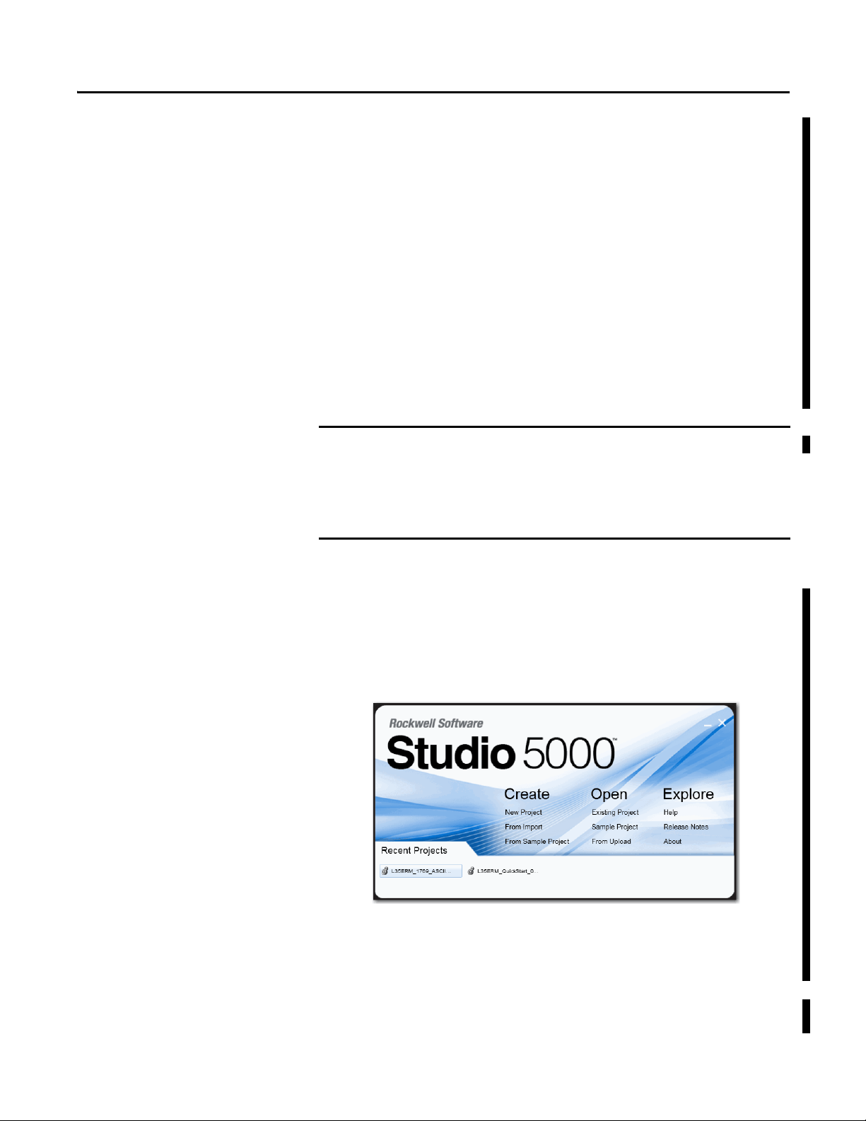
Studio 5000 Environment
The Studio 5000 Engineering and Design Environment combines engineering
and design elements into a common environment. The first element in the Studio
5000 environment is the Logix Designer application. The Logix Designer
application is the rebranding of RSLogix 5000 software and will continue to be
the product to program Logix5000™ controllers for discrete, process, batch,
motion, safety, and drive-based solutions.
The Studio 5000 environment is the foundation for the future of Rockwell
Automation® engineering design tools and capabilities. It is the one place for
design engineers to develop all of the elements of their control system.
You use RSLogix500™ software to configure the 1769-ASCII module with a
MicroLogix1500 controller.
Rockwell Automation Publication 1769-UM012B-EN-P - January 2014 7
Page 8

Preface
Additional Resources
These documents contain additional information concerning related products
from Rockwell Automation.
Resource Description
CompactLogix 5370 L3 Controllers, Revision 20
Release Notes 1769-RN020
Compact I/O DeviceNet Adapter User Manual,
publication 1769-UM001
Logix5000 Controllers ASCII Strings Programming
Manual, publication 1756-PM013
Compact I/O DeviceNet Scanner Module User Manual,
publication 1769-UM009
1768 CompactLogix L4x Controllers User Manua l,
publication 1768-UM001
CompactLogix L2x User Manual,
publication 1769-UM007
CompactLogix L3x User Manual, publication
1769-UM011
Industrial Automation Wiring and Grounding
Guidelines, publication 1770-4.1
Product Certifications website,
http://www.ab.com
Describes enhancements, known anomalies, and
restrictions for CompactLogix 5370 L3 controllers,
firmware revisions 20.011…20.013
Provides details regarding the installation, configuration,
and operation of DeviceNet adapters.
Provides details on how to manipulate ASCII strings in
Logix5000 controllers.
Provides details regarding the installation, configuration,
and operation of DeviceNet scanners.
Provides details regarding the installation, configuration,
and operation of the 1768 CompactLogix Controllers,
catalog numbers: 1768-L43, 1768-L45, 1768-L45,
1768-L45S.
Provides details regarding the installation, configuration,
and operation of the 1768 CompactLogix Controllers,
catalog numbers: 1769-L20, 1769-L30.
Provides details regarding the installation, configuration,
and operation of the 1768 CompactLogix Controllers,
catalog numbers: 1769-L31, 1769-L32C, 1769-L32E,
1769-L35CR, 1769-L35E.
Provides general guidelines for installing a Rockwell
Automation industrial system.
Provides declarations of conformity, certificates, and other
certification details.
Example Programs
You can view or download publications at
http://www.rockwellautomation.com/literature/
. To order paper copies of
technical documentation, contact your local Allen-Bradley distributor or
Rockwell Automation sales representative.
To access these Logix Designer programs, see the Knowledgebase Technote #
64203 at https://rockwellautomation.custhelp.com/app/answers/detail/a_id/
64203.
8 Rockwell Automation Publication 1769-UM012B-EN-P - January 2014
Page 9

Chapter 1
1a
2a
3a
3b
1b
2b
2a
2b
4
Compact I/O ASCII Module
The 1769-ASCII module provides a flexible network interface to a wide variety
of RS-232, RS-485, and RS-422 ASCII devices.
Top ic Pag e
About the Module 9
Environment and En closure 10
North American Hazardous Location Approval 11
European Hazardous Location Approval 12
Install the Module 13
Assemble the System 14
Ground the Module 17
Connect the D-sub Connector Pins 18
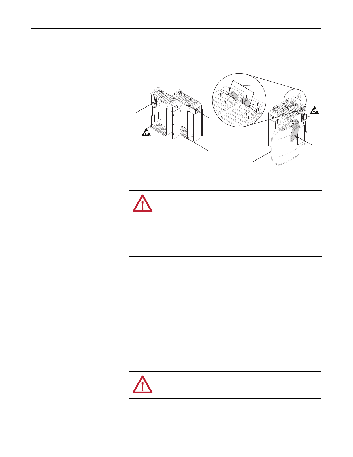
About the Module
The module provides the communication connections to the ASCII device.
Item Description
1a Upper DIN rail latch
1b Lower DIN rail latch
2a Upper tongue-and-groove slots
2b Lower tongue-and-groove slots
3a Channel 0 isolated ASCII connec tor
3b Channel 1 isolated ASCII connector
4 Stationary bus connector with male pins
Rockwell Automation Publication 1769-UM012B-EN-P - January 2014 9
Page 10

Chapter 1 Compact I/O ASCII Module
Environment and Enclosure
WARNING: This equipment is intended for use in a Pollution Degree 2
industrial environment, in overvoltage Category II applications (as defined in
IEC publication 60664-1), at altitudes up to 2000 meters (6562 ft) without
derating.
This equipment is considered Group 1, Class A industrial equipment according to
IEC/CISPR Publication 11. Without appropriate precautions, there may be
potential difficulties ensuring electromagnetic compatibility in other
environments due to conducted as well as radiated disturbance.
This equipment is supplied as open-type equipment. It must be mounted within
an enclosure that is suitably designed for those specific environmental
conditions that will be present and appropriately designed to prevent personal
injury resulting from accessibility to live parts. The enclosure must have suitable
flame-retardant properties to prevent or minimize the spread of flame,
complying with a flame spread rating of 5VA, V2, V1, V0 (or equivalent) if nonmetallic. The interior of the enclosure must be accessible only by the use of a
tool. Subsequent sections of this publication may contain additional information
regarding specific enclosure type ratings that are required to comply with certain
product safety certifications. In addition to this publication, see the following:
• Industrial Automation Wiring and Grounding Guidelines, Allen-Bradley
publication 1770-4.1
• NEMA Standards publication 250 and IEC publication 60529, as applicable,
for explanations of the degrees of protection provided by different types of
enclosure
, for additional installation requirements
10 Rockwell Automation Publication 1769-UM012B-EN-P - January 2014
Page 11
North American Hazardous Location Approval
Compact I/O ASCII Module Chapter 1
The following information applies when operating this
equipment in hazardous locations.
Products marked `CL I, DIV 2, GP A, B, C, D’ are
suitable for use in Class I Division 2 Groups A, B, C, D,
Hazardous Locations and nonhazardous locations
only. Each product is supplied with markings on the
rating nameplate indicating the hazardous location
temperature code. When combining products
within a system, the most adverse temperature
code (lowest `T’ number) may be used to help
determine the overall temperature code of the
system. Combinations of equipment in your system
are subject to investigation by the local Authority
Having Jurisdiction at the time of installation.
WARNIN G:
Explosion Hazard -
• Do not disconnect equipment unless
power has been removed or the area is
known to be nonhazardous.
• Do not disconnect connections to this
equipment unless power has been
removed or the area is known to be
nonhazardous. Secure any external
connections that mate to this equipment
by using screws, sliding latches,
threaded connectors, or other means
provided with this product.
• Substitution of components may impair
suitability for Class I, Division 2.
• If this product contains batteries, they
must only be changed in an area known
to be nonhazardous.
Informations sur l’utilisation de cet équipement en
environnements dangereux.
Les produits marqués `CL I, DIV 2, GP A, B, C, D’ ne
conviennent qu'à une utilisation en environnements de
Classe I Division 2 Groupes A, B, C, D dangereux et non
dangereux. Chaque produit est livré avec des
marquages sur sa plaque d'identification qui indiquent
le code de température pour les environnements
dangereux. Lorsque plusieurs produits sont combinés
dans un système, le code de température le plus
défavorable (code de température le plus faible) peut
être utilisé pour déterminer le code de température
global du système. Les combinaisons d'équipements
dans le système sont sujettes à inspection par les
autorités locales qualifiées au moment de l'installation.
AVERTISSEMENT:
Risque d’Explosion –
• Couper le courant ou s'assurer que
l'environnement est classé non dangereux
avant de débrancher l'équipement.
• Couper le courant ou s'assurer que
l'environnement est classé non dangereux
avant de débrancher les connecteurs. Fixer
tous les connecteurs externes reliés à cet
équipement à l'aide de vis, loquets
coulissants, connecteurs filetés ou autres
moyens fournis avec ce produit.
• La substitution de composants peut rendre
cet équipement inadapté à une utilisation en
environnement de Classe I, Division 2.
• S'assurer que l'environnement est classé non
dangereux avant de changer les piles.
Rockwell Automation Publication 1769-UM012B-EN-P - January 2014 11
Page 12
Chapter 1 Compact I/O ASCII Module
European Hazardous Location Approval
European Zone 2 Certification (The following applies when the product bears the Ex
or EEx Marking.)
This equipment is intended for use in potentially explosive atmospheres as defined by
European Union Directive 94/9/EC and has been found to comply with the Essential Health and
Safety Requirements relating to the design and construction of Category 3 equipment
intended for use in potentially explosive atmospheres, given in Annex II to this Directive.
Compliance with the Essential Health and Safety Requirements has been assured by
compliance with EN 60079-15 and EN 60079-0.
WARNING:
• This equipment must be installed in an enclosure providing at least IP54
protection when applied in Zone 2 environments.
• This equipment shall be used within its specified ratings defined by AllenBradley.
• Provisions shall be made to prevent the rated voltage from being exceeded by
transient disturbances of more than 40% when applied in Zone 2 environments.
• Secure any external connections that mate to this equipment by using screws,
sliding latches, threaded connectors, or other means provided with this product.
• Do not disconnect equipment unless power has been removed or the area is
known to be nonhazardous.
ATTENTION: This equipment is not resistant to sunlight or other sources of
UV radiation.
12 Rockwell Automation Publication 1769-UM012B-EN-P - January 2014
Page 13
Compact I/O ASCII Module Chapter 1
Install the Module
Compact I/O is suitable for use in an industrial environment when installed in
accordance with these instructions. Specifically, this equipment is intended for
(1)
use in clean, dry environments (Pollution Degree 2
exceeding Over Voltage Category II
(2)
(IEC 60664-1).
) and to circuits not
(3)
ATT EN TI ON : Preventing Electrostatic Discharge
This equipment is sensitive to electrostatic discharge, which can cause internal
damage and affect normal operation. Follow these guidelines when you handle
this equipment.
• Touch a grounded object to discharge potential static.
• Wear an approved grounding wriststrap.
• Do not touch connectors or pins on component boards.
• Do not touch circuit components inside the equipment.
• If available, use a static-safe workstation.
When not in use, store the equipment in appropriate static-safe packaging.
WARNING: If you connect or disconnect the serial cable with power applied to
this module or the serial device on the other end of the cable, an electrical arc
can occur. This can cause an explosion in hazardous locations. Be sure that
power is removed or the area is nonhazardous before proceeding.
ATTENTION: This product is grounded through the DIN rail to chassis ground.
Use zinc-plated, yellow-chromate steel DIN rail to assure proper grounding.
The use of other DIN rail materials (for example, aluminum and plastic), which
can corrode, oxidize, or are poor conductors, can result in improper or
intermittent grounding.
(1) Pollution Degree 2 is an environment where, normally, only non-conductive pollution occurs except that occasionally a temporary
conductivity caused by condensations is to be expected.
(2) Over Voltage Category II is the load level section of the electrical distribution system. At this level, transient voltages are controlled
and do not exceed the impulse voltage capability of the product’s insulation.
(3) Pollution Degree 2 and Over Voltage Category II are International Electrotechnical Commission (IEC ) designations.
Rockwell Automation Publication 1769-UM012B-EN-P - January 2014 13
Page 14
Chapter 1 Compact I/O ASCII Module
6
5
4
3
1
1
2
Assemble the System
Attach the module to the controller or an adjacent I/O module before or after
mounting. For mounting instructions, see the Panel Mount
sections. To work with a system that is already mounted, see Replace a Module
section.
1. Disconnect power.
ATT EN TI ON : Remove power before removing or inserting this module. When
you remove or insert a module with power applied, an electrical arc can occur.
An electrical arc can cause personal injury or property damage by:
• sending an erroneous signal to your system’s field devices, causing
unintended machine motion.
• causing an explosion in a hazardous environment.
Electrical arcing causes excessive wear to contacts on both the module and its
mating connector. Worn contacts can create electrical resistance.
or DIN Rail Mount
2. Check that the bus lever of the module to be installed is in the unlocked
(fully right) position.
3. Use the upper and lower tongue-and-groove slots (1) to secure the
modules together or to a controller.
4. Move the module back along the tongue-and-groove slots until the bus
connectors (2) align with each other.
5. Use your fingers or a small screwdriver to push the bus lever back slightly
to clear the positioning tab (3).
6. Move the bus lever fully to the left (4) until it clicks, to enable
communication between the controller and module.
7. Verify that it is locked firmly in place.
8. Attach an end-cap terminator (5) to the last module in the system by using
the tongue-and-groove slots as before.
ATTENTION: When attaching I/O modules, it is important that the bus
connectors are securely locked together to be sure of proper electrical
connection.
14 Rockwell Automation Publication 1769-UM012B-EN-P - January 2014
Page 15
Compact I/O ASCII Module Chapter 1
IMPORTANT
Host Controller
Compact I/O
Compact I/O
Compact I/O
Right End Cap
All dimensions
are in mm (inches). Hole
spacing tolerance:
±0.4 mm (0.016 in.)
For more than 2 modules: (number of modules - 1) X 35 mm (1.38 in.)
Refer to host controller documentationfor this dimension.
132
(5.197)
122.6±0.2
(4.826±0.008)
35
(1.38)
28.5
(1.12)
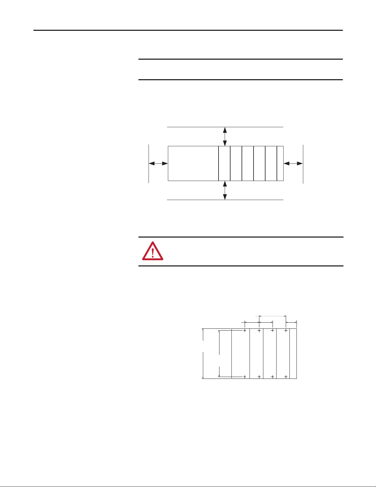
9. Lock the end-cap bus terminator (6).
You must use a 1769-ECR or 1769-ECL right- or left-end cap to terminate
the end of the serial communication bus.
Minimum Space
Maintain spacing, for example, from enclosure walls, wireways, adjacent
equipment. Allow 50 mm (2 in) of space on all sides for adequate ventilation.
Top
Controller
Side Side
Compact I/O
Compact I/O
Bottom
Compact I/O
Compact I/O
End Cap
Compact I/O
Panel Mount
ATT EN TI ON : During panel or DIN rail mounting of all devices, be sure that all
debris (for example, metal chips and wire strand s) is kep t from falling into the
module. Debris that falls into the module could cause damage on powerup.
Mount the module to a panel by using two screws per module. Use M4 or #8
panhead screws. Mounting screws are required on every module.
Panel Mount Procedure with the Dimensional Template
Rockwell Automation Publication 1769-UM012B-EN-P - January 2014 15
Page 16

Chapter 1 Compact I/O ASCII Module
IMPORTANT
Panel Mount Procedure with Modules as a Template
The following procedure lets you use the assembled modules as a template for
drilling holes in the panel. Due to module mounting hole tolerance, it is
important to follow these procedures.
1. On a clean work surface, assemble no more than three modules.
2. Mark the center of all module-mounting holes on the panel by using the
assembled modules as a template.
3. Return the assembled modules to the clean work surface, including any
previously mounted modules.
4. Drill and tap the mounting holes for the recommended M4 or #8 screw.
5. Place the modules back on the panel, and check for proper hole alignment.
6. Use the mounting screws to attach the modules to the panel.
If mounting more modules, mount the last one of this group only and put
the others aside. This reduces remounting time during drilling and tapping
of the next group.
7. Repeat steps 1…6 for any remaining modules.
DIN Rail Mount
When mounting the CompactLogix system, either use screws to panel mount
the system or use DIN rail. Do not use both. Use of both mounting methods
can cause hardware damage and cause the system to fail.
The module can be mounted on these DIN rails:
• 35 x 7.5 mm (EN 50022 - 35 x 7.5)
• 35 x 15 mm (EN 50022 - 35 x 15)
Before mounting the module on a DIN rail, close the DIN rail latches. Press the
DIN rail mounting area of the module against the DIN rail. The latches
momentarily open and lock into place.
16 Rockwell Automation Publication 1769-UM012B-EN-P - January 2014
Page 17

Compact I/O ASCII Module Chapter 1
Replace a Module
The module can be replaced while the system is mounted to a panel or DIN rail.
1. Remove power.
ATTENTION: Remove power before removing or inserting this module. When
you remove or insert a module with power applied, an electrical arc can occur.
An electrical arc can cause personal injury or property damage by:
• sending an erroneous signal to your system’s field devices, causing
unintended machine motion
• causing an explosion in a hazardous environment
Electrical arcing causes excessive wear to contacts on both the module and its
mating connector. Worn contacts can create electrical resistance.
2. Remove the upper and lower mounting screws from the module to be
removed (or open the DIN latches with a screwdriver).
3. Move the bus lever to the right to disconnect (unlock) the bus.
Ground the Module
4. Move the bus lever on the right-side adjacent module to the right (unlock)
to disconnect it from the module to be removed.
5. Gently slide the disconnected module forward.
If you feel excessive resistance, verify that the module is disconnected from
the bus and mounting screws are removed (or DIN latches opened).
If needed, rock the module slightly from front to back to remove it, or, in a
panel-mounted system, to loosen the screws of adjacent modules.
6. Before installing the replacement module, verify that the bus lever on the
replacement module and the right-side adjacent module are unlocked
(fully right) position.
7. Slide the replacement module into the open slot.
8. Connect the modules together by locking (fully left) the bus levers on the
replacement module and the right-side adjacent module.
9. Replace the mounting screws (or snap the module onto the DIN rail).
This product is intended to be mounted to a well-grounded mounting surface
such as a metal panel. Additional grounding connections from the module’s
mounting tabs or DIN rail (if used) are not required unless the mounting surface
cannot be grounded. See Industrial Automation Wiring and Grounding
Guidelines, publication 1770-4.1
, for additional information.
Rockwell Automation Publication 1769-UM012B-EN-P - January 2014 17
Page 18
Chapter 1 Compact I/O ASCII Module
IMPORTANT
NC1
RXD2
TXD3
NC4
COM5
NC6
RTS7
CTS8
NC9
DCD
TXD
RSD
DSR
COM
DTR
CTS
RTS
GND
8
2
3
6
7
20
5
4
1
1
3
2
6
5
4
8
7
(1)
ASCII DTE
DTE
9-pin
25-pin
Connect the D-sub Connector Pins
All the pins are always active.
Pins unused for a particular physical network must not be connected via the
serial cable to any other device. In particular, do not use cables 1747-CP3 and
1756-CP3.
Pin RS-232 RS-422 RS-485
1 Do Not Connect Transmit Data - Transmit/Receive Data -
2 Receive Data Do Not Connect Do Not Connect
3 Transmit Data Do Not Connect Do Not Connect
4 Do Not Connect Receive Data - Do Not Connect
5 Common Common Common
6 Do Not Connect Receive Data + Do Not Connect
7 Request To Send Request To Send Request To Send
8 C le ar To Se nd Cl ea r To S en d Cle ar To Se nd
9 Do Not Connect Transmit Data + Transmit/Receive Data +
Figure 1 - RS-232 Wiring Diagram - Module to DTE Device (hardware handshaking disabled)
(1) Connect to the shield of the cable.
18 Rockwell Automation Publication 1769-UM012B-EN-P - January 2014
Page 19
Compact I/O ASCII Module Chapter 1
NC
NC
NC
1
RXD2
TXD3
4
COM5
6
RTS7
CTS8
N.C.9
CD
TXD
RXD
DSR
COM
DTR
CTS
RTS
RI
8
2
3
6
7
20
5
4
22
1
3
2
6
5
4
8
7
9
GND 1
ASCII DTE DTE
9-pin
25-pin
ASCII
TRXD-
NC
NC
NC
NC
1
2
3
4
COM
RTS
CTS
5
6
7
8
TRXD+9
TRXD-
COM
TRXD+
ASCII
Figure 2 - RS-232 Wiring Diagram - Module to Printer (hardware handshaking enabled, standard
printer adapter cable)
Figure 3 - RS-422 Wiring Diagram
TXD-
1
2
NC
3
NC
4
RXD-
COM5
RXD+
6
7
RTS
8
CTS
TXD+9
Figure 4 - RS-485 Wiring Diagram
Rockwell Automation Publication 1769-UM012B-EN-P - January 2014 19
RXD-
TXDCOM
TXD+
RXD+
Page 20

Chapter 1 Compact I/O ASCII Module
Notes:
20 Rockwell Automation Publication 1769-UM012B-EN-P - January 2014
Page 21

Chapter 2
Configure the 1769-ASCII Module
This chapter describes how to configure and program the 1769-ASCII module
with CompactLogix controllers and the MicroLogix 1500 controller.
Configure the 1769-ASCII
Module
Starting on page 34
1769-ASCII module’s Add-On Profile. The examples use the Add-On Profile
instead of the generic module profile. Using the Add-On Profile saves you time
by making the configuration of the module easier, for example, not having to
input a lot of data.
• Connect to Channel 0 of the Module in Alternating Mode
• Connect to Both Channels of the Module in Alternating Mode on page 41
• Connect to Both Channels of the 1769-ASCII Module in Simultaneous
Mode on page 49
To access these Logix Designer programs, see the Knowledgebase Technote #
64203 at https://rockwellautomation.custhelp.com/app/answers/detail/a_id/
64203.
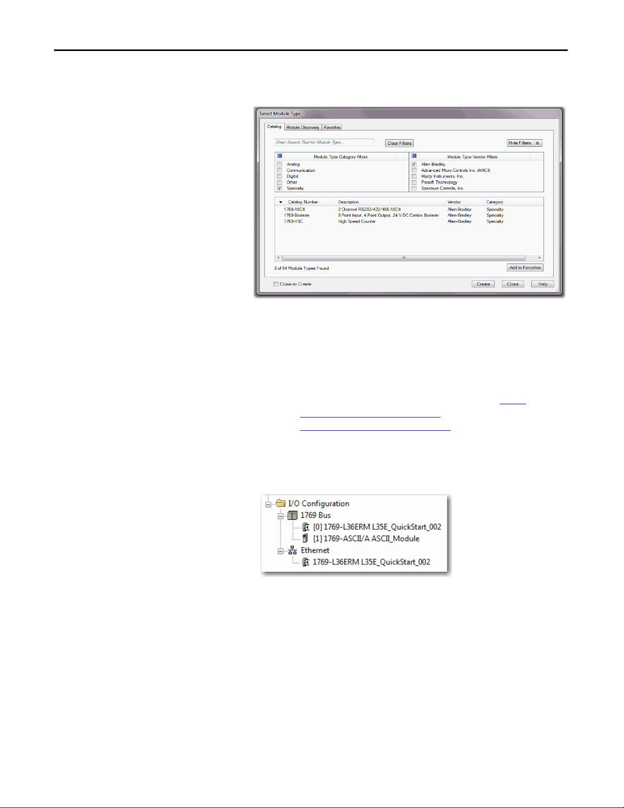
Follow these steps to add and configure the 1769-ASCII module.
1. Right click on the 1769 Compact Bus in your Logix Designer project and
choose New Module.
, there are three example Logix Designer programs using the
on page 34
Rockwell Automation Publication 1769-UM012B-EN-P - January 2014 21
Page 22
Chapter 2 Configure the 1769-ASCII Module
TIP
2. In the Enter test search or module type field, type 1769-ASCII or clear the
checkboxes and check Specialty.
3. Select the 1769-ASCII module and click Create.
4. Close the Select Module Type dialog box.
If you are using RSLogix5000 software, version 16 and later and do not see the
1769-ASCII module as an option, you must download the module’s Add-On
Profile.
The Add-On Profile can be downloaded and installed from https://
download.rockwellautomation.com/esd/
download.aspx?downloadid=addonprofiles
RSLogix5000 software, version 16 is the minimum revision compatible with
the 1769-ASCII module Add-On-Profile.
The module appears in the configuration tree.
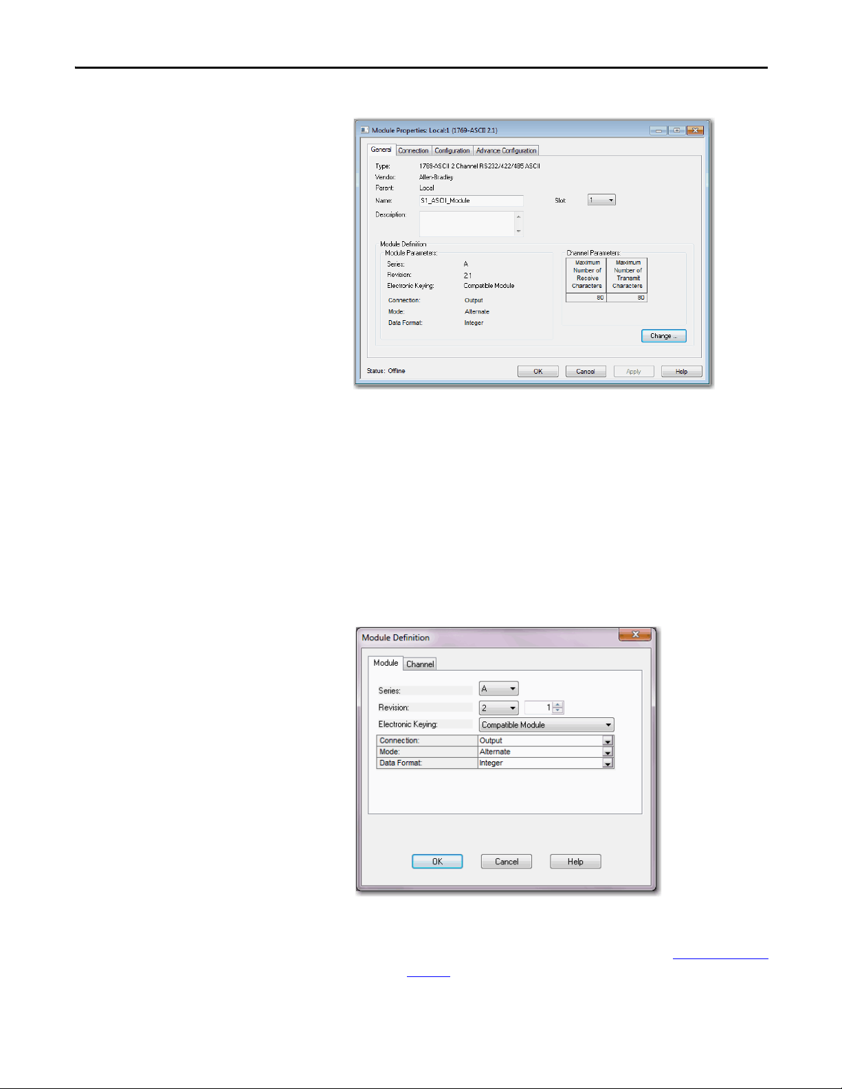
5. Right-click on the module and choose Properties.
22 Rockwell Automation Publication 1769-UM012B-EN-P - January 2014
Page 23
Configure the 1769-ASCII Module Chapter 2
TIP
The Module Properties Dialog box appears.
6. Review and make sure you have the correct module.
7. Typ e a name.
8. Type a description, if needed.
9. Assign a slot number to the module.
10. Review the Module Definition area and make sure the information is
correct.
11. Click Change on the General tab to modify the module definition
parameters.
The Module Definition box appears.
The examples used later in this chapter, has electronic keying disabled but
compatible keying is suggested. For mor information, see Electronic Keying
on
page 105.
Rockwell Automation Publication 1769-UM012B-EN-P - January 2014 23
Page 24

Chapter 2 Configure the 1769-ASCII Module
TIP
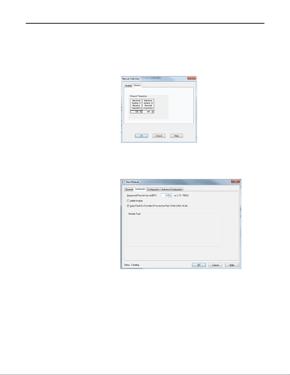
Module Definition Dialog Box
The Module Definition dialog box contains a set of configuration parameters
that affects data transmission between the controller and the I/O module.
Online edits are not possible when the controller is in RUN mode. Online edits
must be made only when the controller is in Remote Run or Program modes.
The Change button on the Module Properties General tab provides access where
the listed parameters can be changed.
This is where you specify the Series, Revision, and Electronic Keying. You can do
the following:
• Choose connection type
• Select alternating or simultaneous mode
• Assign the data format type
Table 1 - Module Definition Parameters Descriptions
Parameter Description
Series Module’s hardware series.
Revision Major and minor firmware revision levels used on the module.
Electronic Keying When you configure a module, you specify the slot number for the module. However, it is
Connection The connection type between the controller writing the configuration and the I/O module is
Data Format Integer data transferred between the controller and I/O module and what tags are generated
possible to purposely or accidentally place a different module in that slot. Electronic keying lets
you protect your system against the accidental placement of the wrong module in a slot. The
chosen keying option determines how closely any module in a slot must match the
configuration for that slot before the controller opens a connection to the module. There are
different keying options depending on your application needs. See Using Electronic Keying
page 105 for detailed information.
Output.
when the configuration is complete.
on
24 Rockwell Automation Publication 1769-UM012B-EN-P - January 2014
Page 25
Configure the 1769-ASCII Module Chapter 2
1. In the Module Definition dialog box click the Channel tab.
2. Configure channel parameters and click OK.
Each channel can be configured for 4…200 characters. For Simultaneous
Mode, the sum of Channel 1 and Channel 2 for Receive and Transmit
characters cannot exceed 200 bytes.
The module's RPI can be configured through Connection tab. RPI can be
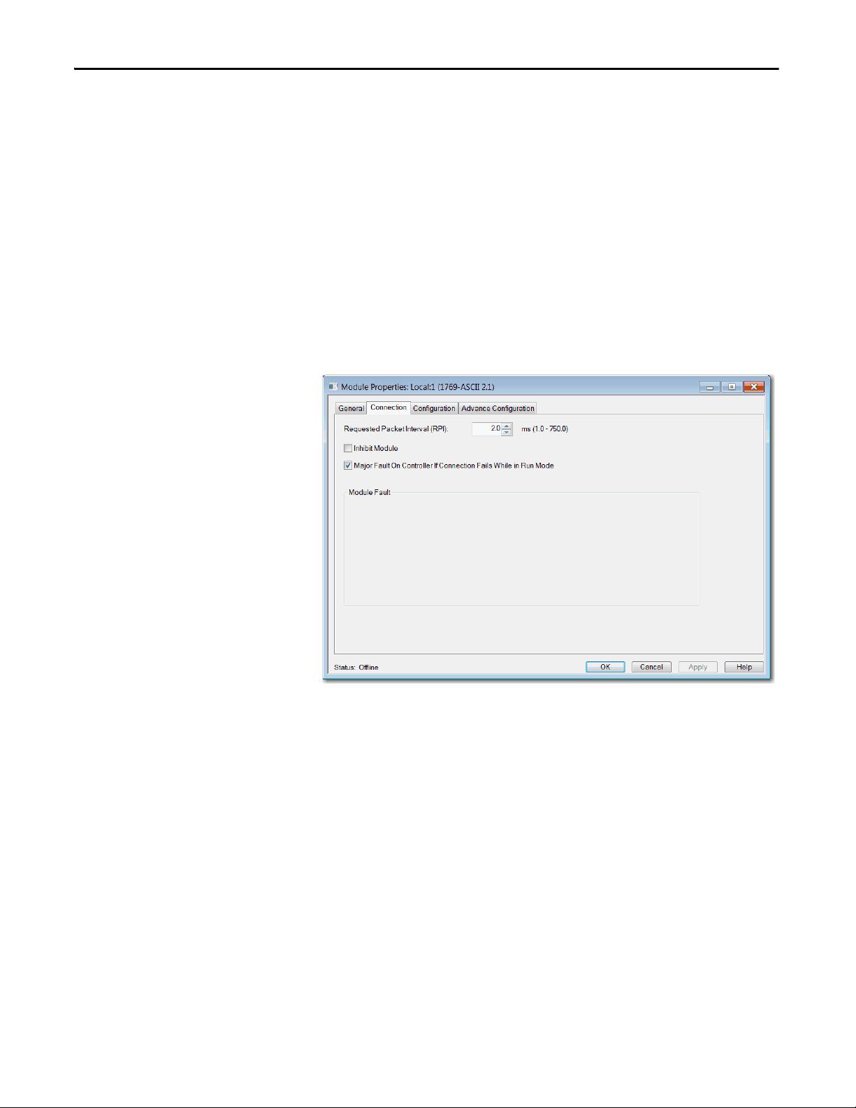
configured in multiples of 0.5. The RPI can be configured for 1.0 - 750.0 in
multiples of 0.5ms. Values entered are rounded down to nearest multiple of
0.5ms. for example 2.1ms is rounded down to 2.0ms.
ASCII protocol configuration can be done under Configuration tab. Channels 0
and 1 can have different configuration. Advanced ASCII protocol configuration
like Byte Swap Mode can be done under Advanced Configuration tab. Channels
0 and 1 can have different advanced configurations.
Rockwell Automation Publication 1769-UM012B-EN-P - January 2014 25
Page 26
Chapter 2 Configure the 1769-ASCII Module
TIP
1769-ASCII Module Connections Dialog Box
This tab displays information about the condition of the connection between the
module and the controller.
Online edits are not possible when the controller is in RUN mode. Online edits
must be made only when the controller is in Remote Run or Program modes.
Use this tab to define controller to module behavior.
• Select a requested packet interval (RPI)
• Choose to inhibit or uninhibit the module
• Configure the controller so that a loss of connection to this module causes
a major fault
• View module faults
26 Rockwell Automation Publication 1769-UM012B-EN-P - January 2014
Page 27

Configure the 1769-ASCII Module Chapter 2
Table 2 - Connection Tab Descriptions
Parameter Descriptions
RPI Enter the requested rate of packet arrival (connection update rate). The RPI specifies the interval at which data is transmitted or received
Major Fault on Controller If Connection
Fails While in Run Mode
Inhibit Module Check or Uncheck this box to inhibit/uninhibit your connection to the module. Inhibiting the module causes the connection to the
Module Fault View module faults.
over a connection. When scanned on the local bus or over an EtherNet/IP network, I/O modules are scanned at the RPI specified in the
module configuration.
Typically, you configure an RPI in milliseconds (ms). The connection is s cheduled to move data to or from the module at least this often or
the connection fails with the Connection Not Scheduled fault. The minimum and maximum RPI values are shown parenthetically to the
right of the box/spin control.
This option determines how the controller is affected if the connection to an I/O module fails in Run mode or if the controller is unable to
establish a connection to the module. You can configure the project so that a connection failure causes a major fault on the controller or
not. The default setting is for the option to be disabled.
For example, if this option is enabled and an I/O module is removed while in Run mode, a major fault occurs on the controller. The default
setting for the embedded I/O module is that this option is enabled. The default setting for local expansion modules is that this option is
disabled.
module to be broken and may result in lost data. If the module is inhibited, the module in the controller organizer displays the attention
icon.
If you inhibit the module while you are online and connected to the module, the connection to the module is nicely closed. The module's
outputs will go to the last configured Program mode state.
• If you inhibit the module while online but a connection to the module has not been established (due to an error condition or fault),
the module is inhibited. The module status information changes to indicate that the module is 'Inhibited' and not 'Faulted'.
• If you uninhibit a module (clear the checkbox) while online, and no fault condition occurs, a connection is made to the module and the
module is dynamically reconfigured (if you are the owner controller) with the configuration you have created for that module. If you
are a listener (have chosen a ‘Listen Only’ Communications Format), you cannot re-configure the module.
• If you uninhibit a module while online and a fault condition occurs, a connection is not made to the module.
These are some common message that you may see in the Module Fault area.
Connection Request Error
The controller is attempting to make a connection to the module and has received an error. The connection was not made.
Service Request Error
The controller is attempting to request a service from the module and has received an error. The service was not performed successfully.
Module Configuration Invalid
The configuration in the module is invalid. (This error is commonly caused by the Electronic Key Passed fault.)
Electronic Keying Mismatch
Electronic Keying is enabled and some part of the keying information differs between the software and the module.
Rockwell Automation Publication 1769-UM012B-EN-P - January 2014 27
Page 28
Chapter 2 Configure the 1769-ASCII Module
TIP
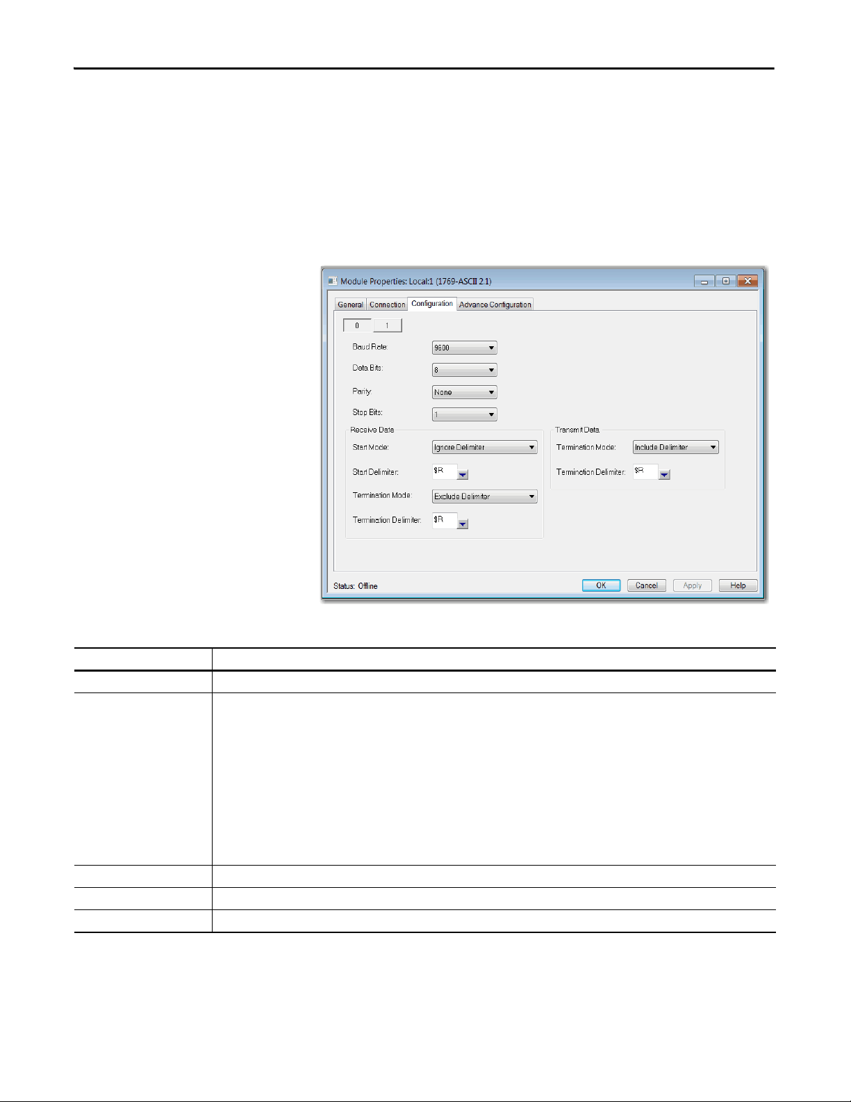
1769-ASCII Module Configuration Dialog Box
Use this dialog box to configure the ASCII parameters.
Online edits to a module's configuration do not take effect until the module
connection is reestablished. This can be done by inhibiting/uninhibited the
module using the checkbox on Connection tab. The module operation is
interrupted while connection is inhibited.
Table 3 - Module Properties Dialog Box - Configuration Tab Parameter Descriptions
Parameter Description
Channel Choose the channel (0 or 1) for which parameters are configured.
Baud Rate Enter the b aud rate for the channel. Valid values are as follows.
1200
2400
4800
9600 (default)
19,200
38,400
57,600
115,200
Baud Rate appears dimmed when controller is in Run mode. Online edits can only be done when the mode or key switch is in the Remote or
Program position.
Serial Data Formats Use Data Bits, Parity, and Stop Bits to configure serial data formats.
Data Bits Choose 7 (default) or 8 for the Data Bits. Data Bits appears dimmed Run mode.
Parity Choose Odd, Even, or None (default) for the Parity. Parity appears dimmed Run mode.
28 Rockwell Automation Publication 1769-UM012B-EN-P - January 2014
Page 29

Configure the 1769-ASCII Module Chapter 2
Table 3 - Module Properties Dialog Box - Configuration Tab Parameter Descriptions (Continued)
Parameter Description
Stop Bits Choose 1 or 2 (default) for the Stop Bits. Stop Bits appear dimmed Run mode. These are the Valid Data Bits, Parity, and Stop Bits combinations
Data Bits Parity Stop Bits
7None2
7Even1
7Odd1
7Even2
7Odd2
8None1
8None2
8Even1
8Odd1
Receive Data Start Mode
Termination Mode Configure the channel’s termination mode. These are the valid values.
Termination Delimiter Configure the channel’s termination delimiter. Valid values are any ASCII character (7 bit – 0…127; 8 bit – 0…255). The following special
Transmit Data Configure the channel’s termination mode. These are the valid values.
• Ignore Delimiter (default)
• Exclude Delimiter
• Include Delimiter
Start Mode appears dimmed Run mode.
Start Delimiter
Valid values are any ASCII character (7 bit – 0…127; 8 bit – 0…255). These are the supported special characters.
Character Description
$$ Dollar Sign ($24)
$’ Single Quote ($27)
$L Line Feed ($0A)
$P Form Feed ($0C)
$R Carriage Return ($0D)
$T Tab ($09)
Start Delimiter appears dimmed.
• Ignore Delimiter
• Exclude Delimiter
• Include Delimiter (default)
Termination Mode appears dimmed in Run mode.
characters are supported.
Character Description
$$ Dollar Sign ($24)
$’ Single Quote ($27)
$L Line Feed ($0A)
$P Form Feed ($0C)
$R Carriage Return ($0D)
$T Tab ($09)
Termination Delimiter appears dimmed in Run mode.
• Ignore Delimiter
• Exclude Delimiter
• Include Delimiter (default)
Termination Mode appears dimmed in Run mode.
Rockwell Automation Publication 1769-UM012B-EN-P - January 2014 29
Page 30
Chapter 2 Configure the 1769-ASCII Module
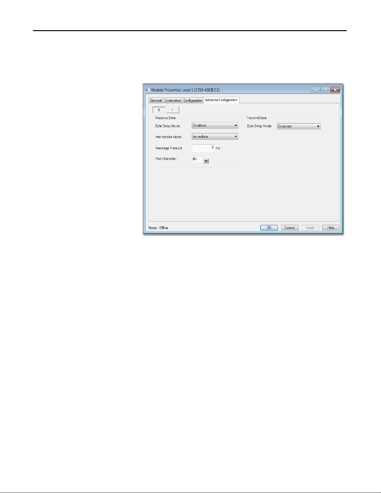
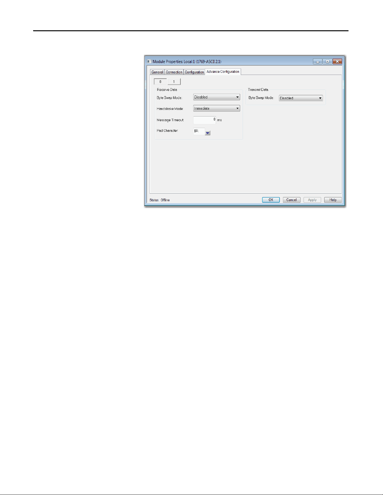
1769-ASCII Module Advanced Configuration Dialog Box
Use this dialog box to configure advanced parameters, such as receiving and
transmitting data.
30 Rockwell Automation Publication 1769-UM012B-EN-P - January 2014
Page 31

Configure the 1769-ASCII Module Chapter 2
Table 4 - Advanced Configuration Parameters Descriptions
Parameter Description
Channel Choose the channel (0 or 1) for which parameters are configured.
Receive Data Byte Swap Mode
These are the valid values.
• Disabled (default)
• 2 – bytes
• 4 – bytes
Byte Swap Mode appears dimmed in Run mode.
Handshake Mode
These are the valid values.
• Master/Slave
• Immediate (default)
• Handshake Mode appears dimmed in Run mode.
Message Timeout
Valid values are in the range of 0…65,535. The default value is 0.
Message Timeout appears dimmed in Run mode.
Pad
Set the pad character for receive data. Valid values are any ASCII character (7 bit – 0…127; 8
bit – 0…255). These are the special characters supported.
Character Description
$$ Dollar Sign ($24)
$’ Single Quote ($27)
$L Line Feed ($0A)
$P Form Feed ($0C)
$R (default) Carriage Return ($0D)
$T Tab ($09)
Pad appears dimmed in Run mode.
Tra nsm it D ata Byte Swap Mode
These are the valid values.
• Disabled (default)
• 2 – bytes
• 4 – bytes
Byte Swap Mode appears dimmed in Run mode.
Rockwell Automation Publication 1769-UM012B-EN-P - January 2014 31
Page 32
Chapter 2 Configure the 1769-ASCII Module
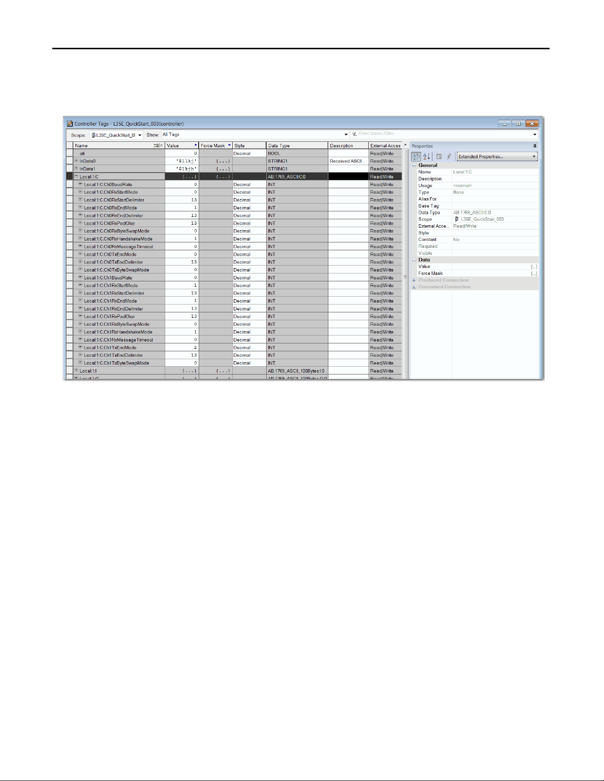
Controller-scoped Tags
This is an example of a Controller-Scoped configuration tags.
Data Types
These are the Module-Defined data types that are used in the following exercises.
The 1769-ASCII Add-On Profile displays the data types with a descriptive name.
These dialog boxes differ slightly depending on whether you select Alternating or
Simultaneous mode.
32 Rockwell Automation Publication 1769-UM012B-EN-P - January 2014
Page 33
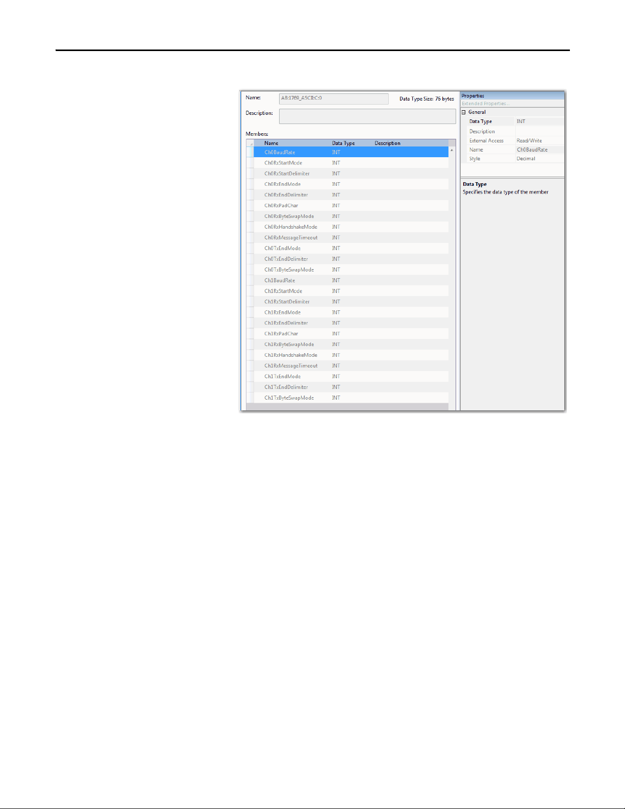
This is an example of Module-Defined data types.
Configure the 1769-ASCII Module Chapter 2
Rockwell Automation Publication 1769-UM012B-EN-P - January 2014 33
Page 34

Chapter 2 Configure the 1769-ASCII Module
TIP
TIP
Connect to Channel 0 of the Module in Alternating Mode
This example program illustrates connecting the serial cable from your computer
to channel 0 of the 1769-ASCII module in alternating mode.
For more detailed information about the Alternate and Simultaneous modes, see
I/O Memory Mapping on page 71
To access the Logix Designer programs, see the Knowledgebase Technote #
64203 at https://rockwellautomation.custhelp.com/app/answers/detail/a_id/
64203.
See Connect the D-sub Connector Pins on page 18 for detailed information on
how to build the appropriate cable for the RS-232 connection between PC with
a serial port and the 1769-ASCII module D-sub connector.
If your computer does not have an RS-232 port, you can use a USB to RS-232
adapter.
.
34 Rockwell Automation Publication 1769-UM012B-EN-P - January 2014
Page 35

Configure the 1769-ASCII Module Chapter 2
Ladder Logic Example
This example illustrates connecting the cable from your computer to channel 0 of
the 1769-ASCII module in alternating mode. This is the ladder logic in the Logix
Designer program, L35ERM_QuickStart_002_V16.ACD.
Main Routine
The Main Routine resets the values of input and output lengths. This zeroes the
data in and out.
Rockwell Automation Publication 1769-UM012B-EN-P - January 2014 35
Page 36
Chapter 2 Configure the 1769-ASCII Module
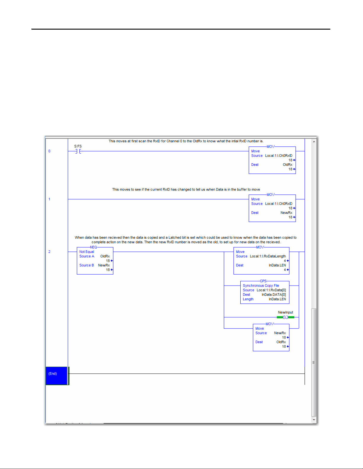
Input Ladder
The Input ladder does the following tasks:
• Moves the RxID for Channel 0, at first scan, to the OldRx. This identifies
the initial RxID number.
• Moves to see if the current RxID has changed that tells when the Data is in
the buffer ready to be moved.
• Receives data and then the data is copied. A Latched bit is set that
identifies when the data has been copied to complete action on the new
data. Then the new RxID number is moved as the old to set up for new
data on the received.
36 Rockwell Automation Publication 1769-UM012B-EN-P - January 2014
Page 37
Configure the 1769-ASCII Module Chapter 2
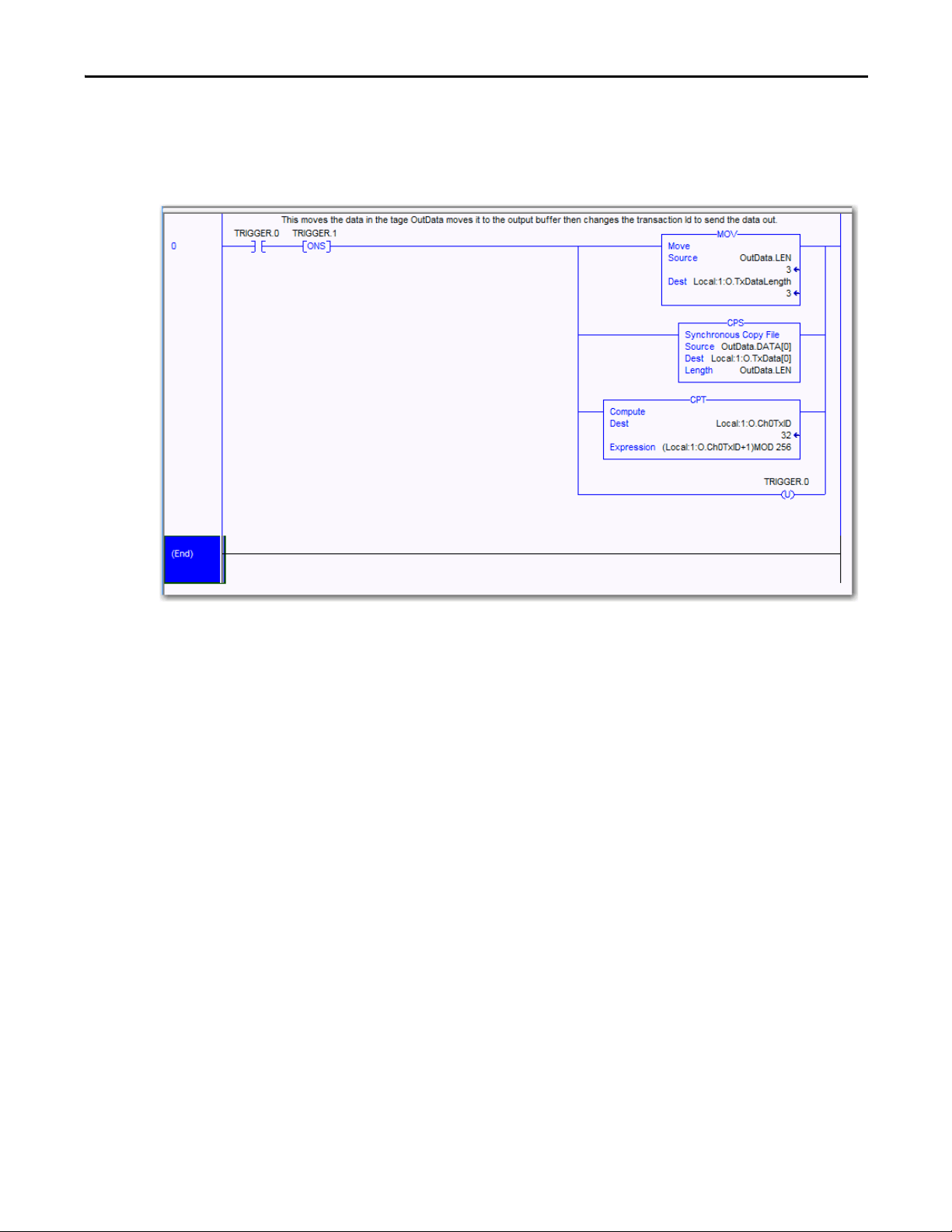
Output Ladder
The Output ladder moves the data in the tag. OutData moves it to the output
buffer then changes the transaction ID to send the data out.
Rockwell Automation Publication 1769-UM012B-EN-P - January 2014 37
Page 38
Chapter 2 Configure the 1769-ASCII Module
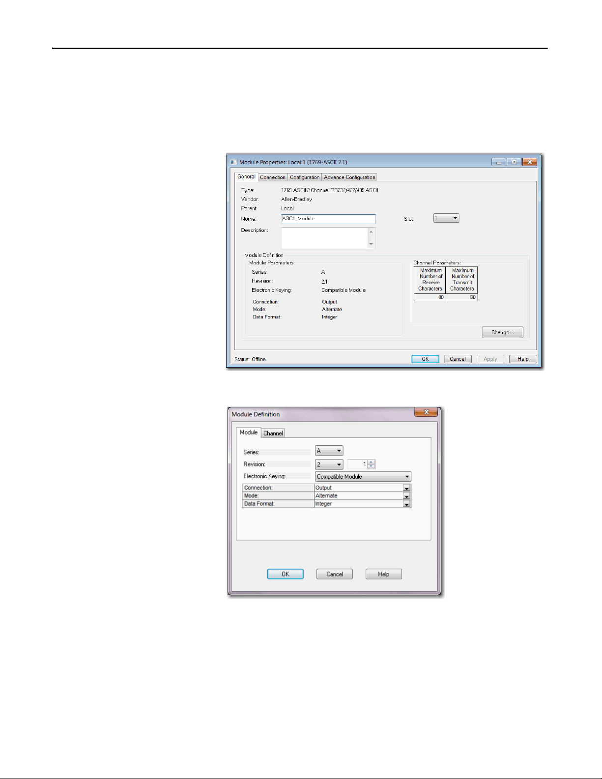
Configure the Module Properties
Use the Module Properties dialog box to configure parameters for the module.
The following screens illustrate example module settings.
1769-ASCII Module General Dialog Box
Module Definition Dialog Box
38 Rockwell Automation Publication 1769-UM012B-EN-P - January 2014
Page 39

1769-ASCII Module Connection Dialog Box
Configure the 1769-ASCII Module Chapter 2
1769-ASCII Module Configuration Dialog Box
Rockwell Automation Publication 1769-UM012B-EN-P - January 2014 39
Page 40
Chapter 2 Configure the 1769-ASCII Module
1769-ASCII Module Advanced Configuration Dialog Box
40 Rockwell Automation Publication 1769-UM012B-EN-P - January 2014
Page 41

Configure the 1769-ASCII Module Chapter 2
TIP
TIP
Connect to Both Channels of the Module in Alternating Mode
This example program illustrates connecting the serial cable from your computer
to both channels of the 1769-ASCII module in alternating mode.
For more detailed information about the Alternate and Simultaneous modes, see
I/O Memory Mapping on page 71
See Connect the D-sub Connector Pins on page 18 for detailed information on
how to build the appropriate cable for the RS-232 connection between PC with
a serial port and the 1769-ASCII module D-sub connector.
If your computer does not have an RS-232 port, you can use a USB to RS-232
adapter.
To access the Logix Designer programs, see the Knowledgebase Technote #
64203 at https://rockwellautomation.custhelp.com/app/answers/detail/a_id/
64203.
.
Rockwell Automation Publication 1769-UM012B-EN-P - January 2014 41
Page 42

Chapter 2 Configure the 1769-ASCII Module
Ladder Logic Example
This ladder logic example illustrates how to connect to both channels of the
module in alternating mode. This is the ladder logic in the Logix Designer
program, L35ERM_QuickStart_003_V16.ACD
Main Routine
The Main Routine Zeros out the InData & OutData array lengths.
42 Rockwell Automation Publication 1769-UM012B-EN-P - January 2014
Page 43

Configure the 1769-ASCII Module Chapter 2
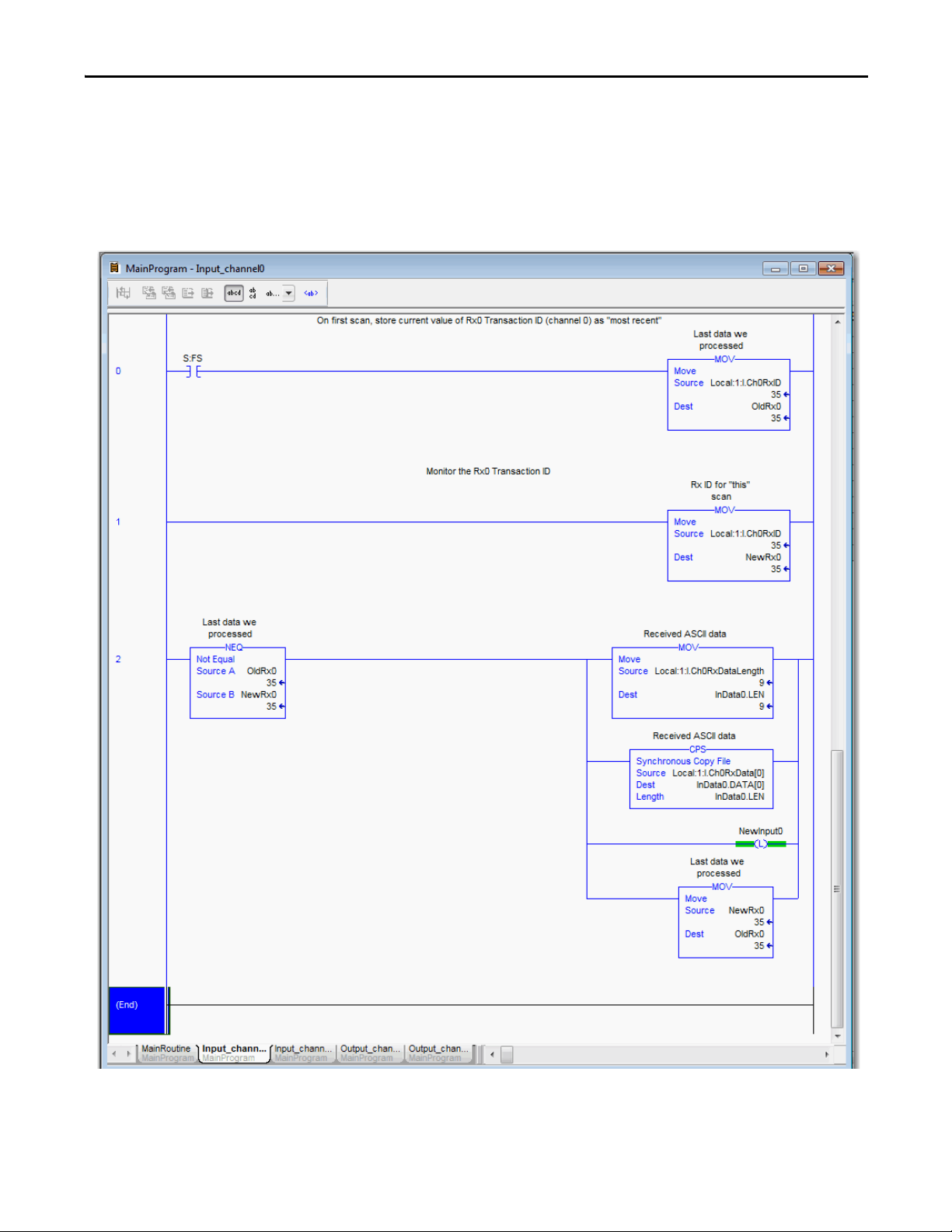
Input Channel0
The Input Channel0 does the following tasks:
• On first scan, stores current value of Rx0 Transaction ID (channel 0) as
‘most recent’.
• Monitors the Rx0 Transaction ID.
Rockwell Automation Publication 1769-UM012B-EN-P - January 2014 43
Page 44
Chapter 2 Configure the 1769-ASCII Module
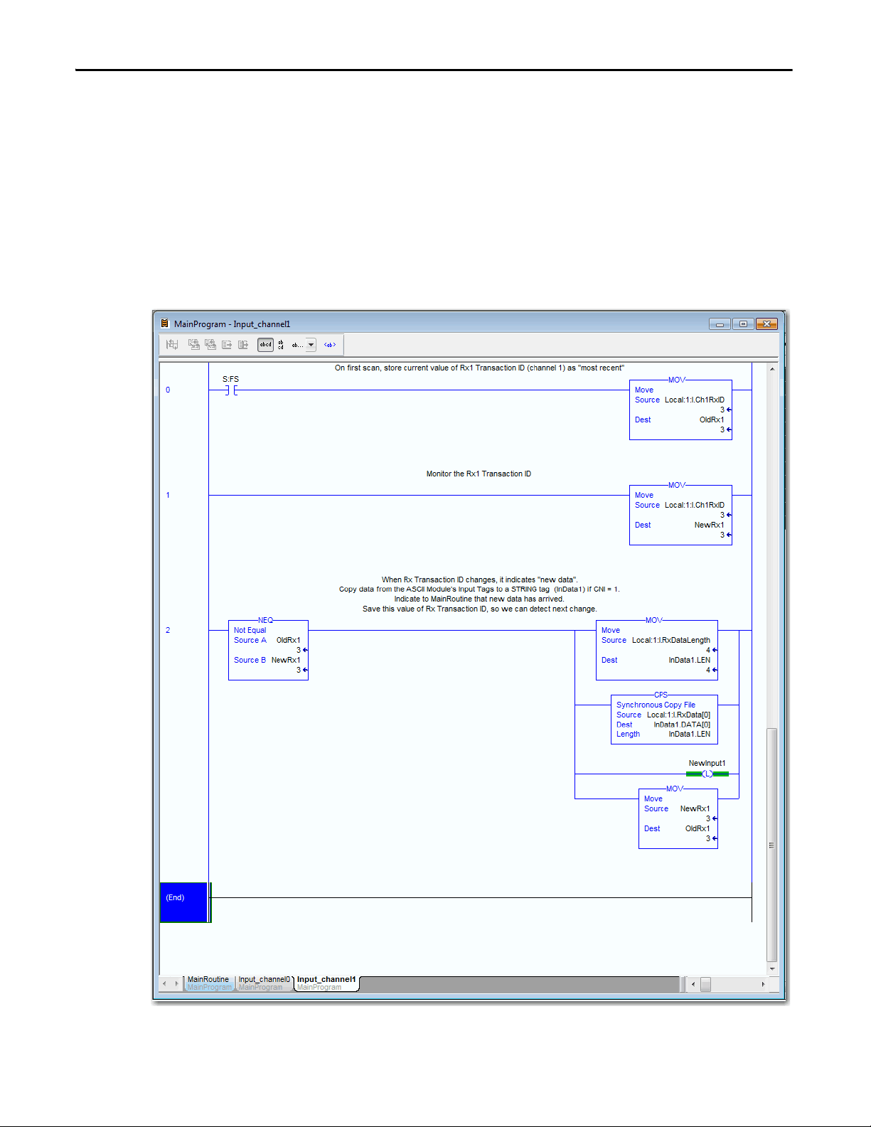
Input Channel1
The Input Channel1 does the following tasks:
• On first scan, store current value of Rx1 Transaction ID (channel 1) as
‘most recent’
• When the Rx Transaction ID changes, it indicates there is ‘new data.’
• Copies data from the module's Input Tags to a STRING tag
(InData1) if CNI = 1.
• Indicates to the MainRoutine that new data has arrived. Saves this value of
Rx Transaction ID, so you can detect the next change.
44 Rockwell Automation Publication 1769-UM012B-EN-P - January 2014
Page 45
Configure the 1769-ASCII Module Chapter 2
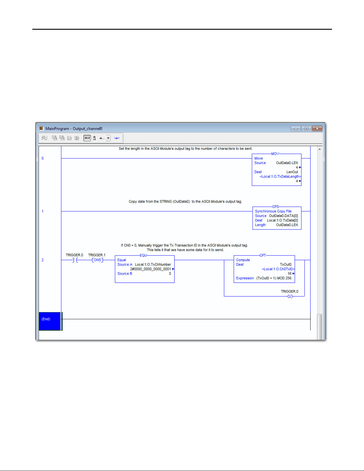
Output Channel0
The Output Channel0 does the following tasks:
• Sets the length in the module's output tag to the number of characters to
be sent.
• Copies the data from the STRING (OutData0) to the module's output
tag.
• If CN0 = 0, manually triggers the Tx Transaction ID in the 1769-ASCII
Module's output tag. This tells it that you have some data for it to send.
Rockwell Automation Publication 1769-UM012B-EN-P - January 2014 45
Page 46

Chapter 2 Configure the 1769-ASCII Module
Output Channel1
The Output Channel1 does the following tasks:
• Sets the length in the module's output tag to the number of characters to
be sent.
• Copies data from the STRING (OutData1) to the module's output tag.
• If CN0 = 1, manually triggers the Tx Transaction ID in the module's
output tag. This tells it that you have some data for it to send.
46 Rockwell Automation Publication 1769-UM012B-EN-P - January 2014
Page 47

1769-ASCII Module General Dialog Box
Configure the 1769-ASCII Module Chapter 2
1769-ASCII Module Connection Dialog Box
Rockwell Automation Publication 1769-UM012B-EN-P - January 2014 47
Page 48

Chapter 2 Configure the 1769-ASCII Module
1769-ASCII Module Configuration Dialog Box
1769-ASCII Module Advanced Configuration Dialog Box
48 Rockwell Automation Publication 1769-UM012B-EN-P - January 2014
Page 49

Configure the 1769-ASCII Module Chapter 2
TIP
TIP
Connect to Both Channels of the 1769-ASCII Module in Simultaneous Mode
This example program illustrates connecting the serial cable from your computer
to both channels of the 1769-ASCII module.
See Connect the D-sub Connector Pins on page 18 for detailed information on
how to build the appropriate cable for the RS-232 connection between PC with
a serial port and the 1769-ASCII module D-sub connector.
If your computer does not have an RS-232 port, you can use a USB to RS-232
adapter.
For more detailed information about the Alternate and Simultaneous modes, see
I/O Memory Mapping on page 71
To access the Logix Designer programs, see the Knowledgebase Technote #
64203 at https://rockwellautomation.custhelp.com/app/answers/detail/a_id/
64203.
.
Rockwell Automation Publication 1769-UM012B-EN-P - January 2014 49
Page 50

Chapter 2 Configure the 1769-ASCII Module
Ladder Logic Example
This is the ladder logic in the Logix Designer project,
L35ERM_QuickStart_004_V16.ACD. This example program illustrates
connecting the cable from your computer to both channels of the 1769-ASCII
module.
Main Routine
The Main Routine zeros out the InData & OutData arrays.
50 Rockwell Automation Publication 1769-UM012B-EN-P - January 2014
Page 51
Configure the 1769-ASCII Module Chapter 2
Input Channel0
The Input Channel0 does the following tasks:
• Stores the current value, on the first scan, as the current value of Rx0
Transaction ID (channel 0) as most recent.
• Monitors the Rx0 Transaction ID
Rockwell Automation Publication 1769-UM012B-EN-P - January 2014 51
Page 52

Chapter 2 Configure the 1769-ASCII Module
Input Channel1
The Input Channel1 does the following tasks:
• Stores the current value, on first scan, of Rx Transaction ID (channel 1) as
most recent.
• Monitors the lower 8 bits of Rx Transaction ID (upper 8 bit are Tx)
• Indicates new data when the Rx Transaction ID changes.
• Copies the data from the module's Input Tags to a STRING tag
(InData1).
• Indicates to the MainRoutine that new data has arrived.
• Saves the value of Rx Transaction ID, so you can detect next change.
52 Rockwell Automation Publication 1769-UM012B-EN-P - January 2014
Page 53

Configure the 1769-ASCII Module Chapter 2
Output Channel0
The Output Channel0 does the following tasks:
• Copies the data from the STRING (OutData0) to the module's output
tag.
• Copies the Length of the number of bytes of the OutputData0 array.
• Triggers the Tx Transaction ID in the module's output tag. This tells it that
you have some data for it to send.
Rockwell Automation Publication 1769-UM012B-EN-P - January 2014 53
Page 54
Chapter 2 Configure the 1769-ASCII Module
Output Channel1
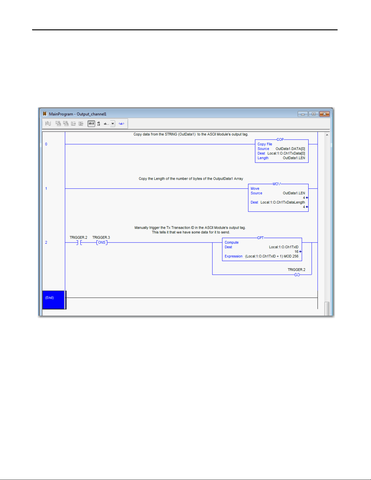
The Output Channel1 does the following tasks:
• Copies data from the STRING (OutData1) to the module's output tag.
• Copies the Length of the number of bytes of the OutputData1 array.
• Triggers the Tx Transaction ID in the module's output tag. This tells it that
you have some data for it to send.
54 Rockwell Automation Publication 1769-UM012B-EN-P - January 2014
Page 55

Configure the 1769-ASCII Module Chapter 2
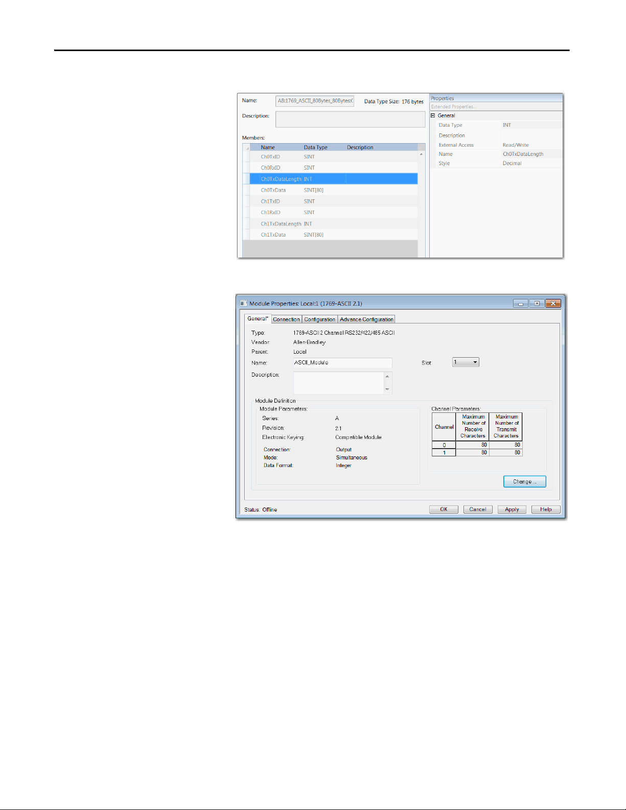
When the I/O module properties appear, enter the following information: a
name, the appropriate slot number, specify a Comm Format of Data_INT, and
enter the following values:
Data Type: AB:1769_ASCII:C:0
Data Type: AB:1769_ASCII_80Bytes_80Bytes:I:0
Rockwell Automation Publication 1769-UM012B-EN-P - January 2014 55
Page 56
Chapter 2 Configure the 1769-ASCII Module
Data Type: AB:1769_ASCII_80Bytes_80Bytes:O:0
1769-ASCII Module General Dialog Box
56 Rockwell Automation Publication 1769-UM012B-EN-P - January 2014
Page 57
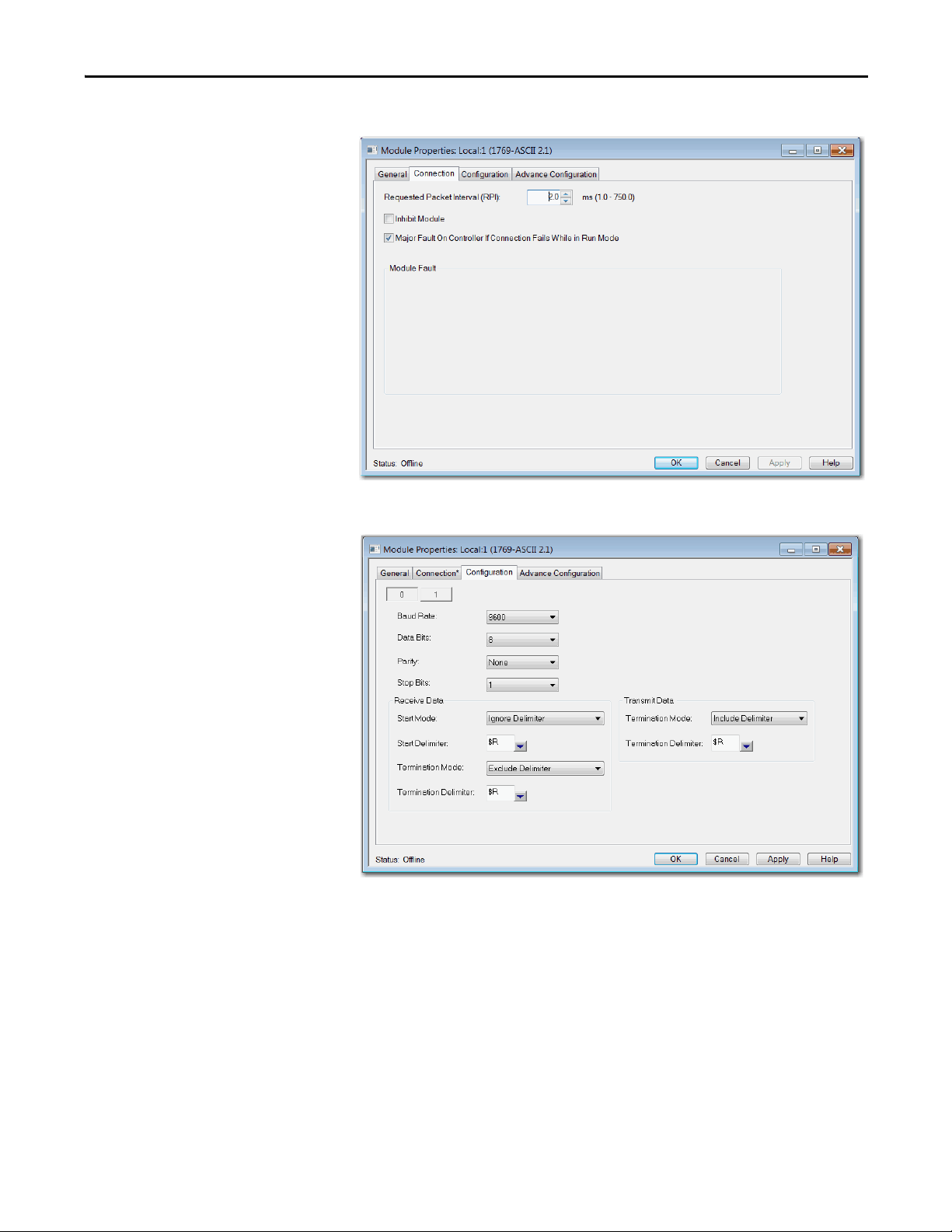
1769-ASCII Module Connection Dialog Box
Configure the 1769-ASCII Module Chapter 2
1769-ASCII Module Configuration Dialog Box
Rockwell Automation Publication 1769-UM012B-EN-P - January 2014 57
Page 58

Chapter 2 Configure the 1769-ASCII Module
1769-ASCII Module Advanced Configuration Dialog Box
58 Rockwell Automation Publication 1769-UM012B-EN-P - January 2014
Page 59

Configure the 1769-ASCII Module Chapter 2
Configure the Module for Use with a MicroLogix Controller
To work with the MicroLogix controller, follow these instructions to prepare the
1769-ASCII module.
1. Open your project.
2. Right-click the 1769-ASCII module and choose Properties.
Make sure Series and Revision match with the hardware.
3. Review and make sure you have the correct module.
4. Typ e a name.
5. Type a Description.
6. Review the Module Definition area and make sure the information is
correct.
7. Click Change on the General tab to modify the module definition
parameters.
Rockwell Automation Publication 1769-UM012B-EN-P - January 2014 59
Page 60

Chapter 2 Configure the 1769-ASCII Module
8. Configure channel parameters under the channel tab.
Each channel can be configured for 4…200 characters. For Simultaneous
Mode, the sum of Channel 1 and Channel 2 for Receive and Transmit
characters cannot exceed 200 bytes.
9. Module's RPI can be configured through Connection tab.
RPI can be configured in multiples of 0.5.
60 Rockwell Automation Publication 1769-UM012B-EN-P - January 2014
Page 61

Configure the 1769-ASCII Module Chapter 2
10. ASCII protocol configuration can be done under Configuration tab.
Channels 0 and 1 can have different configuration.
Advanced ASCII protocol configuration like Byte Swap Mode can be
done under Advanced Configuration tab. Channels 0 and 1 can have
different advanced configurations.
Rockwell Automation Publication 1769-UM012B-EN-P - January 2014 61
Page 62

Chapter 2 Configure the 1769-ASCII Module
Programming Example: MicroLogix 1500 Controller
This MicroLogix example demonstrates how the 1769-ASCII module's channel
0 collects a line of input from the HyperTerminal and echoes that line to you.
To make sure your 1769-ASCII module is functioning properly, follow these
instructions.
1. Open the RSLogix 500 software.
2. Create a project.
In this example, the name of the project is Micro1500_Quickstart_001.
3. In the project space, double-click I/O Configuration.
4. Select the slot number.
In this example, the 1769-ASCII module is in slot 1.
5. From the list, select Other: Requires I/O Card Type ID.
6. When the I/O module properties appear, enter the following information.
Assembly Instance Size
Input 101 108
Output 100 108
Configuration 102 31
7. Click OK.
8. Click Adv. Config.
62 Rockwell Automation Publication 1769-UM012B-EN-P - January 2014
Page 63

Configure the 1769-ASCII Module Chapter 2
9. From the Generic Extra Data Config tab, enter your application data by
referring to the Configuration File.
10. Click OK.
11. Create your program by using these tags.
Rockwell Automation Publication 1769-UM012B-EN-P - January 2014 63
Page 64

Chapter 2 Configure the 1769-ASCII Module
The RSLogix 500 software has data files in the project space to create
different tags. In this example, the following tags were used.
Name Type File Ref Value
InData String ST11:0 Empty
OutData String ST11:1 Enter your string
NewInput Bool B3:0 0
NewRx Int N7:1 0
OldRx Int N7:0 0
Intermediate Storage Int N7:2 0
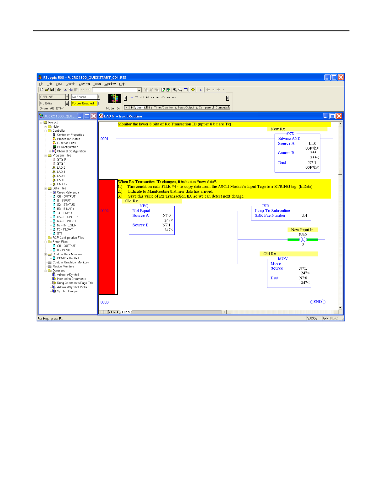
• Input
64 Rockwell Automation Publication 1769-UM012B-EN-P - January 2014
Page 65

Configure the 1769-ASCII Module Chapter 2
Rockwell Automation Publication 1769-UM012B-EN-P - January 2014 65
Page 66

Chapter 2 Configure the 1769-ASCII Module
• Output
66 Rockwell Automation Publication 1769-UM012B-EN-P - January 2014
Page 67

Configure the 1769-ASCII Module Chapter 2
Rockwell Automation Publication 1769-UM012B-EN-P - January 2014 67
Page 68
Chapter 2 Configure the 1769-ASCII Module
• Tr an sf er fr om inp ut to ou tp ut
This figure indicates that the output is triggered when input is received.
12. Download your program to the controller.
13. Place the controller in Run mode.
14. Connect the computer to the 1769-ASCII module.
Connect channel 0 of the 1769-ASCII module to a COM port of your
computer with a cable constructed per the specifications on page 21
15. Run the HyperTerminal application.
16. Configure HyperTerminal so that the configuration matches the ASCII
device for communication rate and framing.
17. Turn off flow control.
18. In the HyperTerminal application, type in a value.
19. Press enter.
68 Rockwell Automation Publication 1769-UM012B-EN-P - January 2014
.
Page 69

Configure the 1769-ASCII Module Chapter 2
The 1769-ASCII module returns text data entered into Outdata tag back
to your screen.
This is not an echo program. Input is received and stored in a string file
Indata (ST11:0). New data triggers the output from another file Outdata
(ST11:1). The data back on the terminal is not the same as the data sent
from the terminal. You must put in a data string in Outdata (ST11:1)
before running the program.
Rockwell Automation Publication 1769-UM012B-EN-P - January 2014 69
Page 70

Chapter 2 Configure the 1769-ASCII Module
Notes:
70 Rockwell Automation Publication 1769-UM012B-EN-P - January 2014
Page 71

Chapter 3
I/O Memory Mapping
When both serial channels are active, you can alternate between receiving data in
the buffer from both ports simultaneously or one at a time.
ASCII Module Behavior when not in Run Mode
The 1769-ASCII module transmits data out the serial port when the controller is
only in Run mode. It sends data once the Tx Transaction ID changes after the
controller transitions into Run mode.
The 1769-ASCII module delivers data received on the serial ports to the
controller even when it is not in Run mode. When not in Run mode, the module
acts as if Master Handshaking is not enabled. Therefore, new data is placed in the
input tag and the Rx Transaction ID increments. When it receives new serial data
after the transition to Run mode, the module follows whatever rules are
configured then. In your program, use the Rx Transaction ID value in the input
tag on the first scan to compare for new data.
Rockwell Automation Publication 1769-UM012B-EN-P - January 2014 71
Page 72
Chapter 3 I/O Memory Mapping
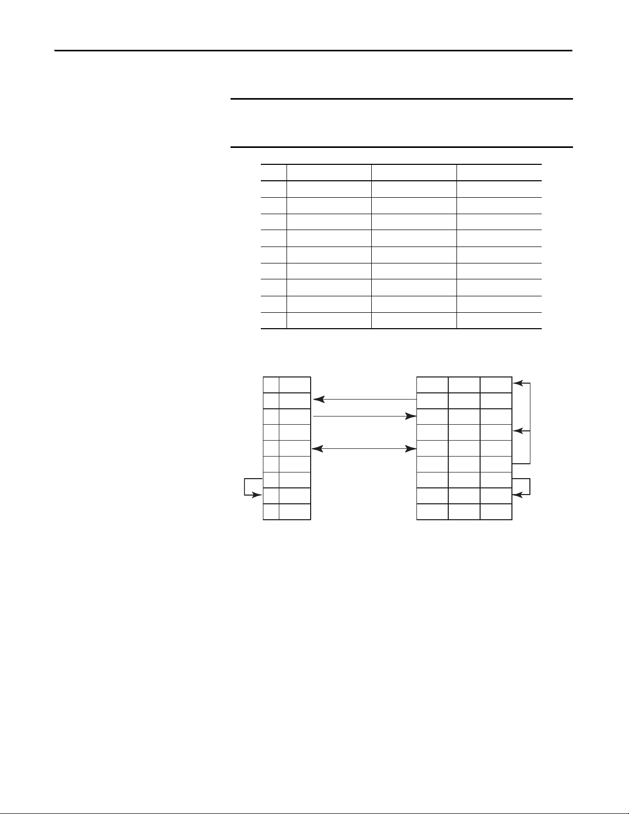
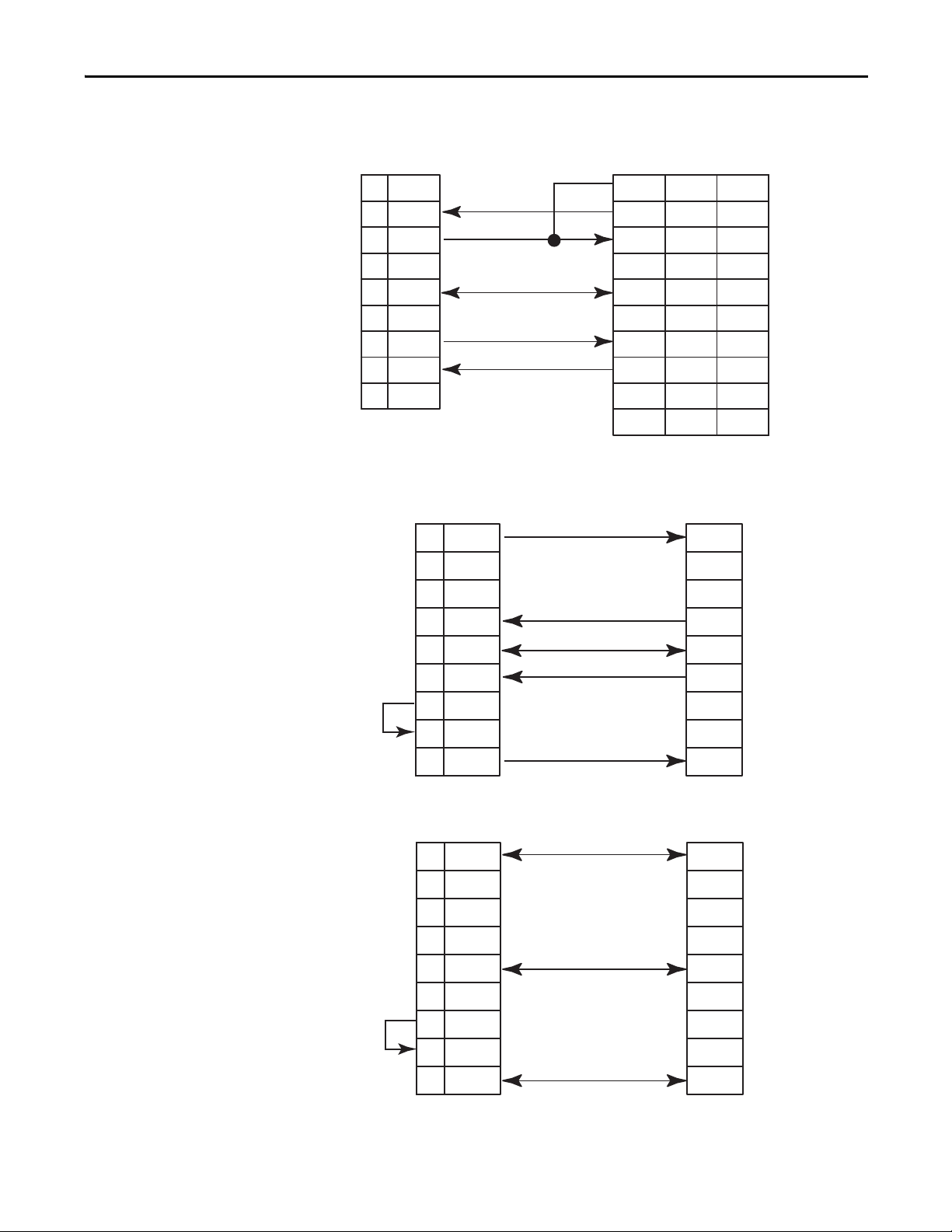
Alternate Mode (one channel at a time) Output File
The alternate mode output file contains the real-time output data from the
module. This table shows the generic module tag definitions on the left. On the
right of the table is the 1769-ASCII module Add-On Profile configuration using
RSLogix 5000 software version 16 and later.
It is assumed that 16 bit words are used. The structure on the left is used with
varying data types; SINT, INT, BOOL and SINT array for data. The Add-On
Profile structures the module output, configuration and input tags differently.
With the Add-On Profile the configuration tags are rearranged as INTs.
The table shows the maximum size of the value and shows the maximum array
size for Alternate Mode.
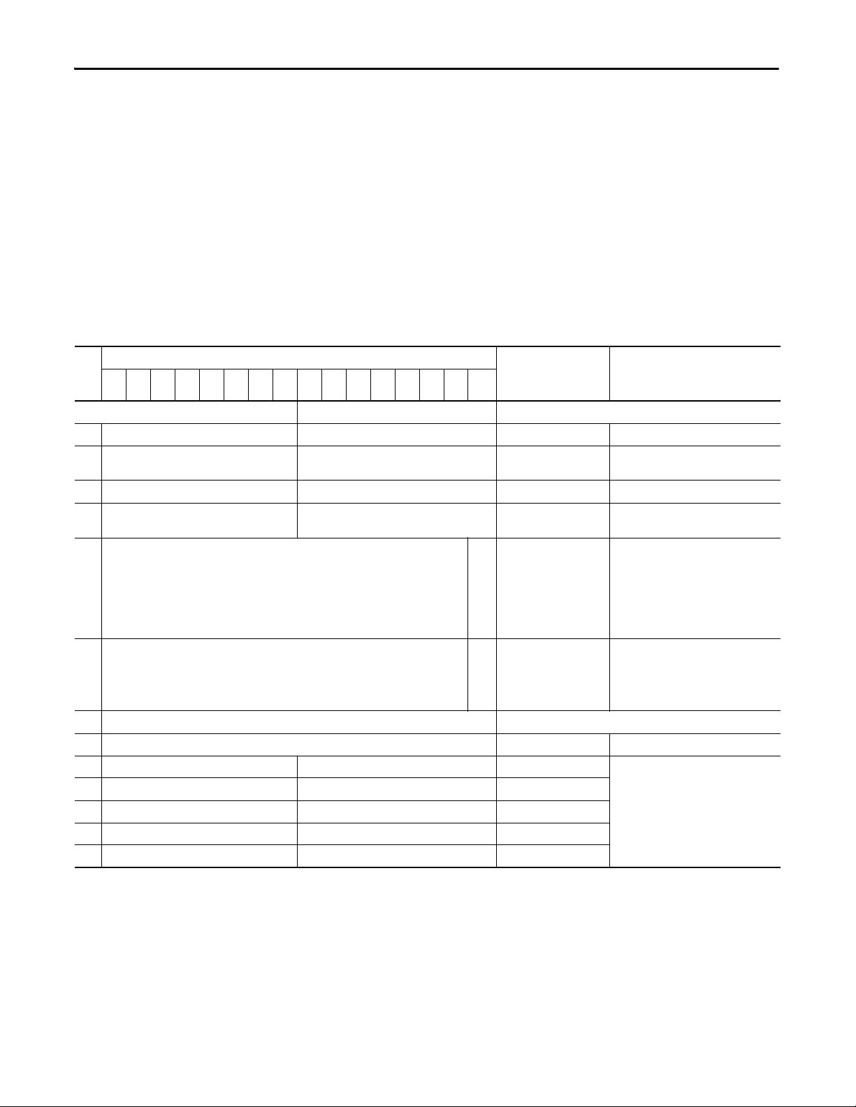
Table 5 - Alternate Mode (one channel at a time) Output File
W
O
R
15 14 13 12 11 10 9 8 7 6 5 4 3 2 1 0
D
0 Reserved
1 Reserved Rx Transaction ID Request Ch0 Local:S:O.Ch0RxID
2 Reserved Tx Transaction ID Ch1 Local:S:O.Ch1TxID Transmit Transaction ID.
3 Reserved Rx Transaction ID Request Ch1 Local:S:O.Ch1RxID
4 Reserved CNI Local:S:O.RxChNumber Channel number of requested input data.
5 Reserved CNO Local:S:O.TxChNumber Channel number of the output data being
6Reserved
7 Length (Number of Bytes) Local:S:O.TxDataLength The amount of data being transmitted.
8 Character 1 Character 0 Local:S:O.TxData This defines the transmit ASCII character
9 Character 3 Character 2 Local:S:O.TxData
… Character … Character … Local:S:O.TxData
106 Character 197 Character 196 Local:S:O.TxData
107 Character 199 Character 198 Local:S:O.TxData
(1)
Bit Position
Add-On-Profile Tag
Name
Generic Module Tag Names
Tx Transaction ID Ch0 Local:S:O.Ch0TxID
Description
(2)
(3)
(4)
Transmit Transaction ID.
Receive Transaction ID Request. Used with
Ch1RxID for handshake mode.
Receive Transaction ID Request. Used with
Ch0RxID for handshake mode.
This bit is set by the PLC controller or
other user program to tell the 1769-ASCII
module which data to produce.
This bit is set by the controller based on
the user program; same for all the words
in the Output data file
sent. This bit is set by the PLC controller or
other user program to tell the module
which port’s data is being sent to the
1769-ASCII module.
for the tag.
(1) Reserved is expected in 1st instance word 0.
(2) Tag name format is `Local:S:O’ where 'S' represents slot number.
(3) Used for handshaking mode.
(4) Used for handshaking mode.
72 Rockwell Automation Publication 1769-UM012B-EN-P - January 2014
Page 73

I/O Memory Mapping Chapter 3
Alternate Mode (one channel at a time) Input File
One channel’s data is received and stored in the input file at a time. The Channel
Number (CN) bit defines the channel whose data is returned. The alternate
mode input file contains the real-time input data from the module with a header
and data section for each channel. This table illustrates the maximum size
allowed.
Table 6 - Alternate Mode (one channel at a time) Input File Tags
Bit Position
15 14 13 12 11 10 9 8 7 6 5 4 3 2 1 0
Word
Generic Module Tag Names
0 Tx ID 0 Acknowledged Rx Transaction ID Ch0 Local:S:I.Ch0TxIACK
1Reserved
2 Tx ID 1 Acknowledged Rx Transaction ID Ch1 Local:S:I.Ch0TxAck
3 151413121110TG1TS1ND1HE1NR1RF1TF1PA1RO1TO1Local:S:I.Ch1Status Ch1 Status. See Status Descriptions
4 Reserved CNI Local:S:I.RxChNumber Channel number of the input data. This bit is set by
5 Reserved CNO Local:S:I.TxChNumber Channel number of the output data most recently
Firmware Revision, Major Firmware Revision, Minor
6 Length (Number of Bytes) Local:S:I.RxDataLength The amount of data being received.
7Reserved
8 Character 1 Character 0 Local:S:I.RxData This defines the receive ASCII character for the tag.
9 Character 3 Character 2 Local:S:I.RxData
… Character … Character … Local:S:I.RxData
106 Character 197 Character 196 Local:S:I.RxData
107 Character 199 Character 198 Local:S:I.RxData
(1) Tag name format is `Local:S:I’ where `S’ represents slot number.
(2) Reserved is expected in 1st instance word 0.
(2)
Add-On-Profile Tag
Name
Local:S:I.Ch0RxID
Local:S:I.Ch0Status Ch0 Status. See Status Descripti ons on page 76.
Local:S:I.Ch0RxID
Description
(1)
Receive Transaction ID Request. Used with Ch0RxID
for handshake mode.
Receive Transaction ID Request. Used with Ch1RxID
for handshake mode.
the 1769-ASCII module to tell the user program
from which port the data was received.
received. This bit is set by the ASCII module to tell
the user program that it has received the data to
transmit out the specified port.
on page 76.
Rockwell Automation Publication 1769-UM012B-EN-P - January 2014 73
Page 74

Chapter 3 I/O Memory Mapping
Simultaneous Mode (two channels) Input File
In Simultaneous mode, the data is packed in the buffer as follows:
• Four words of channel 0 header information
• Channel 0 data of a quantity defined by the Max_Receive_Size parameter
• Four words of channel 1 header information
• Channel 1 data of a quantity defined by the Max_Receive_Size parameter
This table illustrates the maximum size allowed.
Table 7 - Simultaneous Mode (two channels) Input File Tag Definitions
Bit Position
1514131211109876543210
Word
Channel 0 Data
Generic Module Tag Names
0 Tx ID Acknowledged Rx Transaction ID Local:S:I.Ch0TxAck
1Reserved
2 Firmware Revision, Major Firmware Revision, Minor Firmware not included in the Add-On
3 Length (Number of Bytes) Local:S:I.Ch0RxDataLength The amount of data being
4 Character 1 Character 0 Local:S:I.Ch0RxData This defines the receive ASCII
5 Character 3 Character 2 Local:S:I.Ch0RxData
… Character … Character … Local:S:I.Ch0RxData
(2)
x
x+1 Tx ID Acknowledged Rx Transaction ID Local:S:I.Ch1TxAck
x+2 Reserved TG1 TS1 ND1 HE1 NR1 RF1 TF1 PA1 RO1 TO1 Local:S:I.Ch1Status See Status Descriptions
x+3 Firmware Revision, Major Firmware Revision, Minor Firmware not included in the Add-On
x+4 Length (Number of Bytes) Local:S:I.Ch1RxDataLength The amount of data being
x+5 Character 1 Character 0 Local:S:I.Ch1RxData This defines the receive ASCII
x+6 Character 3 Character 2 Local:S:I.Ch1RxData
… Character … Character … Local:S:I.Ch1RxData
(3)
y
(1) Reserved is expected in 1st instance word 0.
(2) X is calculated based on the size of Channel 0 data as specified in the input file. Both channels cannot contain 200 characters as the total configuration file size can be only 108 words.
(3) Y is the connection size minus 1, with a maximum value of 107 for a buffer size of 108.
(1)
Last Character Character … Local:S:I.Ch0RxData
Last Character Character … Local:S:I.Ch1RxData
TG0 TS0 ND0 HE0 NR0 RF0 TF0 PA0 RO0 TO0 Local:S:I.Ch0Status See Status Descriptions on page 76.
Channel 1 Data
Add-On-Profile Tag
Name
Local:S:I.Ch0RxID
Local:S:I.Ch1RxID
Description
This is a fee dback s tatus of Tx ID most
recently transmitted.
Receive Transaction ID Request. Used
with Ch1RxID for handshake mode.
Profile.
transmitted.
character for the tag.
This is a feedback status of Rx ID
most recently transmitted.
Receive Transaction ID Request.
on page 76.
Profile.
transmitted.
character for the tag.
74 Rockwell Automation Publication 1769-UM012B-EN-P - January 2014
Page 75

I/O Memory Mapping Chapter 3
Simultaneous Mode (two channels) Output File
In simultaneous mode, the data is packed in the buffer as follows:
• Four words of channel 0 header information
• Channel 0 data of a quantity defined by the Max_Receive_Size parameter
• Four words of channel 1 header information
• Channel 1 data of a quantity defined by the Max_Receive_Size parameter
This table illustrates the maximum size allowed.
Table 8 - Simultaneous Mode (two channels) Output File Tags
Bit Position
15 14 13 12 11 10 9 8 7 6 5 4 3 2 1 0
Word
Channel 0 Data
Generic Module Tag Names
0Reserved
1 Reserved Rx Transaction ID Request Local:S:O.Ch0RxId
2Reserved
3 Length (Number of Bytes) Local:S:O.Ch0TxDataLength The amount of data being transmitted.
4 Character 1 Character 0 Local:S:O.Ch0TxData This defines the transmit ASCII character for
5 Character 3 Character 2 Local:S:O.Ch0TxData
… Character … Character … Local:S:O.Ch0TxData
(3)
x
x+1 Reserved Tx Transaction ID Local:S:O.Ch1TxId Transmit Transaction ID.
x+2 Reserved Rx Transaction ID Request Local:S:O.Ch1RxId
x+3 Reser ved
x+4 Length (Number of Bytes) Local:S:O.Ch1TxDataLength The amount of data being transmitted.
x+5 Character 1 Character 0 Local:S:O.Ch1TxData This defines the transmit ASCII character for
x+6 Character 3 Character 2 Local:S:O.Ch1TxData
… Character … Character … Local:S:O.Ch1TxData
(5)
y
(1) Reserved is expected in 1st instance word 0.
(2) Used for handshaking.
(3) X is calculated based on the size of Channel 0 data as specified in the configuration file. Both channels cannot contain 200 characters as the total configuration size can be only 108 words.
(4) Used for handshaking.
(5) Y is equal to the connection size minus 1, with a maximum value of 107 for a buffer size of 108.
(1)
Last Character Character … Local:S:O.Ch0TxData
Channel 1 Data
Last Character Character … Local:S:O.Ch1TxData
Tx Transaction ID Local:S:O.Ch0TxId Transmit Transaction ID.
Add-On-Profile Tag
Name
(2)
(4)
Descriptions
Receive Transaction ID Request. Used with
Ch1RxID for handshake mode.
the tag.
Receive Transaction ID Request. Used with
Ch0RxID for handshake mode.
the tag.
Rockwell Automation Publication 1769-UM012B-EN-P - January 2014 75
Page 76

Chapter 3 I/O Memory Mapping
Status Descriptions
This table describes the status tags.
Add-On Profile Abbr. Definition
ChxHandshakeError HE Handshake error. Used for Handshake mode only.
ChxNewData ND New data. Used for Handshake mode only.
ChxNonDelimitedRecord NR Non-delimited record. An input record is received and sent to the Compactbus
interface that was not triggered by receiving a delimiter character. This occurs
when either the buffer is filled to its maximum receive size or a Message
Timeout has occurred.
ChxParityError PA Parity error. A parity error has occurred with the received data string. This
usually indicates a mismatch in the serial port setup of the ASCII device and the
Compact module. It can indicate also that noise has occurred on the line and
degraded the signal.
This bit is set when the receive FIFO contains a message that parity error
occurred in on of the incoming bytes. This bit is reset when the receive FIFO is
emptied or when a new message is received with no parity error.
ChxRxFIFOEmpty RF Data in the receive FIFO. The FIFO is not empty. The input FIFO has not sent all
of its data to the CompactBus interface.
ChxRxDataLost RO Receive buffer overflow. Some input data has been lost.
ChxTxFIFOEmpty TF Data in transmit FIFO. The FIFO is not empty. The output FIFO has not sent all of
its data to the ASCII device.
Ch0TxDataOverFlow TG Transmit greater than Max Error. Transmit length in the output file is greater
than the maximum transmit character length in the configuration file.
ChxTxDataLost TO Transmit buffer overflow. Some output data has been lost.
ChxTxDataSent TS Transmit sent. Indicates that the 1769-ASCII module has sent the data
indicated by the Tx Transaction ID and can accept more transmit data.
76 Rockwell Automation Publication 1769-UM012B-EN-P - January 2014
Page 77

I/O Memory Mapping Chapter 3
Configuration File
The 1769-ASCII module supports a configuration assembly that is configured
with the Add-On Profile.
Table 9 - Configuration File Tag Names
Tag Definition
Module Properties Dialog Box 0 Data Buffer Mode 0…1 0 = Alternate mode
Module Properties Dialog Box 1 Serial Character Framing 0…8 0 = 7N2, 1 = 7E1, 2 = 7O1, 3 = 8N1, 4 = 8N2, 5 = 8E1,
Ch0BaudRate 2 Serial Port Speed 0…7 0 = 9600, 1 = 1200, 2 = 2400, 3 = 4800, 4 = 19,200,
Module Properties Dialog Box 3 Max Number of Receive Characters 0…200 In Simultaneous mode, the total number of channel 0 characters plus
Ch0RxStartMode 4 Receive Record Start Mode 0…2 0 = ignore, 1 = exclude, 2 = include start delimiter
Ch0RxStartDelimiter 5 Receive Start Delimiter
Ch0RxEndMode 6 Receive Record End Mode 0…2 0 = ignore, 1 = exclude, 2 = include end delimiter
Ch0RxEndDelimiter 7 Receive End Delimiter
Ch0RxPadChar 8 Pad Character
Ch0RxByteSwapMode 9 Receive Swap Mode 0…2 0 = disabled, 1 = 16-bit, 2 = 32-bit
Ch0RxHandshakeMode 10 Master Handshake Mode 0…1 0 = master/slave handshake, 1 = produce immediate
Ch0RxMessageTimeout 11 Message Time Out 0…65535 0 = none, 1… 65,535 ms
Module Properties Dialog Box 12 Max Number of Transmit Characters 0…200 In Simultaneous mode, the total number of channel 0 characters plus
Ch0TxEndMode 13 Transmit Record End Mode 0…2 0 = ignore, 1 = exclude, 2 = include end delimiter
Ch0TxEndDelimiter 14 Transmit End Delimiter
Ch0TxByteSwapMode 15 Transmit Swap Mode 0…2 0 = disabled, 1 = 16-bit, 2 = 32-bit
Description Values Valid Data Values
Word
1 = Simultaneous mode
Channel 0
6 = 8O1, 7 = 7E2, 8 = 7O2
5 = 38,400, 6 = 57,600, 7 = 115,200 (half-duplex only)
Serial Port Receive Data
channel 1 characters cannot exceed 200
(1)
(1)
Module Production Data
(1)
Serial Port Transmit Data
(1)
0…127/255 0…0x7f (0…127) for 7-bit data
0…0xff (0…255) for 8-bit data
0…127/255 0…0x7f (0…127) for 7-bit data
0…0xff (0…255) for 8-bit data
0…127/255 0…0x7f (0…127) for 7-bit data
0…0xff (0…255) for 8-bit data
channel 1 characters cannot exceed 200
0…127/255 0…0x7f (0…127) for 7-bit data
0…0xff (0…255) for 8-bit data
Rockwell Automation Publication 1769-UM012B-EN-P - January 2014 77
Page 78

Chapter 3 I/O Memory Mapping
Table 9 - Configuration File Tag Names (Continued)
Tag Definition
Module Properties Dialog Box 16 Serial Character Framing 0…8 0 = 7N2, 1 = 7E1, 2 = 7O1, 3 = 8N1, 4 = 8N2, 5 = 8E1,
CH1BaudRate 17 Serial Port Speed 0…7 0 = 9600, 1 = 1200, 2 = 2400, 3 = 4800, 4 = 19200,
Module Properties Dialog Box 18 Max Number of Receive Characters 0…200 In Simultaneous mode, the total number of channel 0 characters plus
Ch1RxStartMode 19 Receive Record Start Mode 0…2 0 = ignore, 1 = exclude, 2 = include start delimiter
Ch1RxStartDelimiter 20 Receive Start Delimiter
Ch1RxEndMode 21 Receive Record End Mode 0…2 0 = ignore, 1 = exclude, 2 = include end delimiter
Ch1RxEndDelimiter 22 Receive End Delimiter
Ch1RxPadChar 23 Pad Character
Ch1RxByteSwapMode 24 Receive Swap Mode 0…2 0 = disabled, 1 = 16-bit, 2 = 32-bit
Ch1RxByteHandshakeMode 25 Master Handshake Mode 0…1 0 = master/slave handshake, 1 = produce immediate
CH1RxMessageTimeout 26 Message Time Out 0…65535 0 = none, 1 to 65535 ms
Module Properties Dialog Box 27 Max Number of Transmit Characters 0…200 In Simultaneous mode, the total number of channel 0 characters plus
Ch1TxEndMode 28 Transmit Record End Mode 0…2 0 = ignore, 1 = exclude, 2 = include end delimiter
Ch1TxEndDelimiter 29 Transmit End Delimiter
Ch1TxByteSwapMode 30 Transmit Swap Mode 0…2 0 = disabled, 1 = 16-bit, 2 = 32-bit
(1) To enter values 128…255, use this conversion formula: Desired Decimal Value - 256 = Entered Decimal Value. For example, for an ASCII character value of 128, 128 - 256 = -128.
Description Values Valid Data Values
Word
Channel 1
6 = 8O1, 7 = 7E2, 8 = 7O2
5 = 38400, 6 = 57.6k, 7 = 115.2k (half-duplex only)
Serial Port Receive Data
channel 1 characters cannot exceed 200.
(1)
0…127/255 0…0x7f (0…127) for 7-bit data
0…0xff (0…255) for 8-bit data
(1)
0…127/255 0…0x7f (0…127) for 7-bit data
0…0xff (0…255) for 8-bit data
Module Production Data
(1)
0…127/255 0…0x7f (0…127) for 7-bit data
0…0xff (0…255) for 8-bit data
Serial Port Transmit Data
channel 1 characters cannot exceed 200.
(1)
0…127/255 0…0x7f (0…127) for 7-bit data
0…0xff (0…255) for 8-bit data
78 Rockwell Automation Publication 1769-UM012B-EN-P - January 2014
Page 79

I/O Memory Mapping Chapter 3
Configuration File Parameter Operation
Each channel’s serial port and data string operation is configured individually and
independently. The parameters that are not independent are the Data Buffer
mode and the Transmit and Receive buffer sizes. The sum of the two channels’
buffer sizes cannot total more than 200 bytes, in each direction, while using the
Simultaneous Buffer mode.
Data Buffer Mode
This parameter defines whether the data is in the Alternate mode or
Simultaneous mode on the CompactBus. You can access the Data Buffer mode in
the Module Definition dialog box. Go to the General tab and click Change.
Set Up the Data Frame Format
The data frame format parameter defines the size of the data frame that is
transmitted and received over the serial link. This parameter defines the
following:
• Number of data bits per character (7 or 8)
• Parity (odd, even, or none)
• Number of stop bits (1 or 2)
The 1769-ASCII module provides several options to match the choices available
with your ASCII device because they must match exactly. Frame format can be
handled also in the Add-On Profile on the Configuration tab.
Although the Add-On-Profile lets you select only six options. You can populate
these configuration tags as documented in the following sections.
Receive Delimiter Mode
The Start Delimiter indicates that the module starts storing data received at its
serial port. The End Delimiter signals the end of data to be stored. If you use a
receive delimiter, you can include or exclude the delimiter in the ASCII message
sent to the CompactBus Master. The Start and Stop Delimiters are used and set
independently of each other:
• If the Start Delimiter is not used, the module receives and stores any valid
characters received after the completion of the previous message.
• If the Stop Delimiter is not used, the module collects data up to the Max
Receive Characters parameter value.
Rockwell Automation Publication 1769-UM012B-EN-P - January 2014 79
Page 80
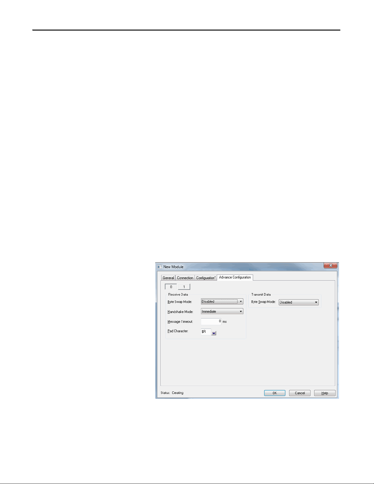
Chapter 3 I/O Memory Mapping
Set Up the Receive Delimiters
The receive Start Delimiter is a start-of-string character used by the 1769-ASCII
module to determine that the first expected character from the ASCII device is
received. Upon receipt of this character, the 1769-ASCII module starts storing
the string data in its internal data buffer on the serial receive side.
The receive Stop Delimiter is an end-of-string character used by the 1769-ASCII
module to determine that the last expected character from the ASCII device is
received. Upon receipt of this character the 1769-ASCII module update its
internal data buffer on the serial receive side. The module also makes the new
string available to the CompactBus Master in the Produce buffer.
The receive delimiters can be set to any valid ASCII character that can be
received over the link. Be sure to avoid setting the delimiter to a value outside of
the valid range for your data bits. For example, a data bit size setting of 7 gives you
a delimiter range of 0…127 decimal, 00…7F hexadecimal.
If you do not receive a valid receive delimiter, the device updates the Produce
buffer on detection of a buffer full (overflow) condition only. For example, the
device updates when it receives the number of characters defined in the Max
Number of Receive Characters parameter. The device also updates if a time-out
occurs (if you selected the time-out option).
The Receive Data, Transmit Data Swap, Handshake mode, MSG Timeout, and
Pad Character are all handled per channel on the Advance Configuration tab in
the Add-On Profile.
80 Rockwell Automation Publication 1769-UM012B-EN-P - January 2014
Page 81

I/O Memory Mapping Chapter 3
Set Up the Transmit Delimiter
The 1769-ASCII module uses the transmit (and exclude) delimiter to determine
the number of bytes to transmit to your ASCII device. The 1769-ASCII module
transmits up to and including the delimiter when the length in the output file
is 0.
If the output file length is not 0, the 1769-ASCII module transmits the number
of bytes/characters specified in the header's length value. The 1769-ASCII
module continues this transmission until the Max Transmit Size is reached. The
transmit delimiter can be set to any valid ASCII character that can be received
over the link.
Be sure to avoid setting the delimiter to a value outside the valid range for your
data bits. For example, a data bit size setting of 7 gives you a delimiter range of
0…127 decimal, 00…7F hexadecimal. Without a valid delimiter, the device
updates the output buffer only on detection of an overflow condition.
Set Up the Receive Character Buffer Length
The Receive Character Buffer Length parameter is the number of characters that
the 1769-ASCII module can receive from the ASCII device into the Input File
buffer. When this value is exceeded, the 1769-ASCII module generates an
overflow, which forces the data into the 1769-ASCII module transmit buffer.
The Produce buffer can include the following:
• A single channel’s data from the 1769-ASCII module to the CompactBus
Master
The channel can return up to 200 bytes of ASCII data.
• Both channels’ data in one buffer from the 1769-ASCII module to the
CompactBus Master (Simultaneous mode)
The Produce buffer returns two ASCII buffers, each proceeded by its’
associated 4-byte header. The combined length of both channels’ data
cannot exceed the module’s 200-byte ASCII buffer limit.
Valid settings for the Receive Character Buffer Length parameter are 0…200. If 0
is selected, the serial port for receiving data is deactivated and header information
in the input file is not updated.
If the total size of the two channels is greater than 200 characters, the Alternate
mode must be used.
Rockwell Automation Publication 1769-UM012B-EN-P - January 2014 81
Page 82

Chapter 3 I/O Memory Mapping
Set Up the Transmit Character Buffer Length
The Transmit Character Buffer Length parameter is the number of characters
that the 1769-ASCII module can receive in its transmit buffer from the
CompactBus Master. This size value determines the maximum size of the
command data sent to the 1769-ASCII module from the Master, that is the
1769-ASCII module Consume Size.
The Consume buffer can include the following:
• A single channel’s data from the 1769-ASCII module to the CompactBus
Master.
The channel can return up to 200 bytes of ASCII data.
• Both channels’ data in one buffer from the 1769-ASCII module to the
CompactBus Master (Simultaneous mode)
The Consume buffer returns two ASCII buffers, each proceeded by its
associated 4-byte header. The combined length of both channels’ data
cannot exceed the module’s 200-byte ASCII buffer limit.
Valid settings for the Transmit Character Buffer Length parameter are 0-200. If 0
is selected, the serial port for data is deactivated. Any information in the output
file is ignored.
If the total size of the two channels is greater than 200 characters, the Alternate
mode must be used.
Receive Data Padding
The 1769-ASCII module uses padding to add extra characters to the end of its
receive data string (after the delimiter character). The 1769-ASCII module add
this padding before sending the string to the CompactBus Master as an I/O
response.
This padding allows for the CompactBus Master to always receive a data string
with a constant length. This length is equal to the one specified in the Receive
Character Length parameter.
You specify the Pad mode character to add to the received serial data, which is
0…127 in 7-bit mode and 0…255 in 8-bit mode.
82 Rockwell Automation Publication 1769-UM012B-EN-P - January 2014
Page 83

I/O Memory Mapping Chapter 3
IMPORTANT
Byte Swap Mode
To help with compatibility with end serial devices, the 1769-ASCII module
supports user-configurable options to byte swap data received from or
transmitted to the ASCII devices. Byte swapping of data is supported on 16- or
32-bit boundaries.
When Byte Swap mode is enabled, the user-defined Receive/Transmit Buffer
Length parameters must be evenly divisible by the bit boundary, 16- or 32-bit.
Byte Swap mode is valid only for nonzero length strings or non-characterterminated data. It does not work with character-terminated strings when
the length byte is left at zero.
Termination characters are counted as part of the length of the nonzero
length strings.
Transmit Serial ASCII Data
The Max Number of Transmit Characters parameter determines whether the
1769-ASCII module transmits data to a serial device.
If TX_String_Length = 0
The 1769-ASCII module receives data sent from the CompactBus Master and
uses the delimiter to determine how much data is sent to the serial device:
• If a transmit (or exclude) delimiter is in the string, all characters up to and
including the defined delimiter are sent to the ASCII device.
• If no delimiter is contained within the string, then the 1769-ASCII
module sends data received from the CompactBus Master to the ASCII
device.
If TX_String_Length > 0
The 1769-ASCII module receives data sent from the CompactBus Master
ignoring any embedded terminator. It sends the number of characters defined in
the Max Number of Transmit Chars parameter or the total sent by the Master,
whichever is less.
Receive ASCII Serial Data
The 1769-ASCII module receives and sends strings as defined in the Max
Number of Receive Characters parameter until the module receives a delimiter.
The 1769-ASCII module also sends the overflow error until a delimiter is
received. This process continues indefinitely until the ASCII device transmits the
specified delimiter.
Rockwell Automation Publication 1769-UM012B-EN-P - January 2014 83
Page 84

Chapter 3 I/O Memory Mapping
IMPORTANT
Receive Timeout
The 1769-ASCII module has a receive timeout value configurable in 1 ms
increments. The timeout counter resets on the receipt of each new byte of data. If
the timeout counter expires, the 1769-ASCII module sets the Non-Delimited
flag in the Status Byte and updates the Receive/Produce buffer with the current
data string.
How to Send Data from the 1769-ASCII Module
The Consume buffer can include one channel's data or combine both channel's
data in one buffer from the CompactBus Master to the 1769-ASCII module.
If you configure the module to accept only one channel's data in the Consume
buffer, the channel can accept up to 200-bytes of ASCII data. The Consume
buffer contains an 8-byte header followed by the channel’s associated ASCII data.
CNI or CNO are tags names from Generic module - the Add-On-Profile term
for indicating which channel to transmit data is Local:S:O.TxChNumber. Bit = 0
indicates channel 0 and Bit = 1 indicates channel 1.
If the module is configured to accept both channels’ data, the Consume buffer
sends two ASCII buffers each preceded by its associated header. Under this
configuration, the combined length of both channels’ data cannot exceed the
modules 200-byte ASCII buffer limit.
The header contains the Transaction ID of the data in the first byte. This value is
set to 0 at the beginning of communication.
The second byte has the handshaking bits to denote which channel's data is
needed in the subsequent Produce buffers, if configured for single-channel
communication. The third and fourth bytes are length indicators. The ensuing
bytes are the data that you wish to send to the 1769-ASCII module.
If you use the Byte-Swap mode, all transaction and receive strings must be
in multiples of 2 bytes.
84 Rockwell Automation Publication 1769-UM012B-EN-P - January 2014
Page 85

I/O Memory Mapping Chapter 3
How to Receive Serial Data from the 1769-ASCII Module
Master/Slave Handshake
The Produce buffer can include one channel's data or combine both channel's
data in one buffer from the 1769-ASCII module to the CompactBus Master. If
you configure the module to return only one channel's data in the Produce buffer,
the channel can return up to 200-bytes of ASCII data.
A CN0 bit in the Consume buffer is allocated to determine which channel’s
ASCII data the CompactBus Master is actively requesting.
If the 1769-ASCII module is configured to return both channels’ data, the
Produce buffer returns two ASCII buffers each proceeded by its associated 8-byte
header. Under this configuration, the combined length of both channels’ data
cannot exceed the module’s 200-byte ASCII buffer limit.
The ASCII data is updated when the delimiter is received, the buffer completely
fills, or when a time-out event occurs. Every time the buffer is updated, for
example, the Transaction ID is increments when the delimiter receives an
overflow condition. The data is valid only up to the received delimiter in your
memory map. The status byte represents information regarding the ASCII data
record received from the ASCII device and handshaking and buffer status flags.
The 1769-ASCII module supports a firmware handshaking protocol to prohibit
the module from overwriting input data before the CompactBus Master reads it.
If this mode is enabled, the 1769-ASCII module does not overwrite existing data
in its receive buffer.
Value Meaning
0 Set New Data Status bit and wait for application to increment record number
1 Automatically increment the record number and show the new data when an end event is received
Rockwell Automation Publication 1769-UM012B-EN-P - January 2014 85
Page 86

Chapter 3 I/O Memory Mapping
Notes:
86 Rockwell Automation Publication 1769-UM012B-EN-P - January 2014
Page 87

Appendix A
Configure the 1769-ASCII Module as a Generic
Module
This example demonstrates a CompactLogix program using channel 0 of the
ASCII module to collect a line of input from HyperTerminal and echo that line
back to you.
For information on the MicroLogix controller, see Configure the Module for Use
with a MicroLogix Controller on page 57.
Use the following quick start to make sure your ASCII module is functioning
properly.
1. Open Logix Designer software.
2. Create a new project.
In this example, the name of the project is L35 CR_Quickstart_001.
3. Create a 1769-MODULE (generic) in the I/O configuration.
4. When the I/O module properties appear, enter the following information:
a name, the appropriate slot number, specify a Comm Format of
Data_INT, and enter the following values:
Assembly Instance Size
Input 101 108
Output 100 108
Configuration 102 31
5. Press OK.
Rockwell Automation Publication 1769-UM012B-EN-P - January 2014 87
Page 88
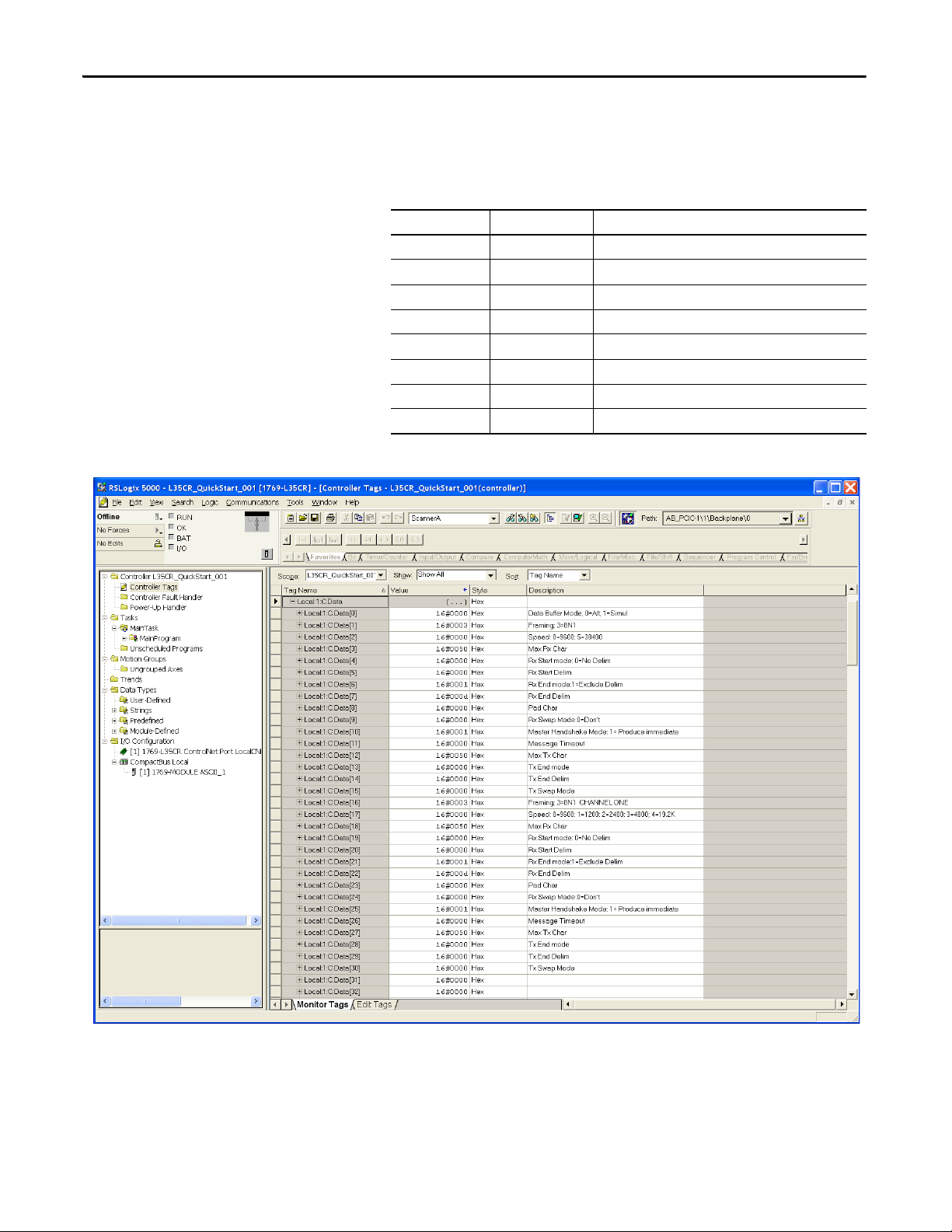
Appendix A Configure the 1769-ASCII Module as a Generic Module
6. Open the controller tags for monitor to enter the following configuration
parameters in the Local:<slot>:C tag data members.
All other parameters are 0.
Data [ ] Word Value (Decimal) Meaning
00 Alternating mode
1 3 Framing is 8N1
2 0 9600 baud
3 80 Max Rx Characters
6 1 Use an Rx End delimiter, but exclude it from the input buffer
7 13 Use a Carriage Return as the Rx End delimiter
10 1 Produce data when available
12 80 Max Tx Characters
This is a controller-scoped configuration tag.
88 Rockwell Automation Publication 1769-UM012B-EN-P - January 2014
Page 89

Configure the 1769-ASCII Module as a Generic Module Appendix A
7. Create your program using these tags.
Name Type Value
Controller-scoped Tags
InData STRING Empty (Len = 0)
OutData STRING Empty (Len = 0)
NewInput BOOL 0
Program-scoped Tags
CrLf STRING A two-character string of $R$L
NewRx INT 0
NumInts INT 0
OldRx INT 0
LenIn Alias to ASCII module’s I:Data[7]
LenOut Alias to ASCII module’s O:Data[7]
TxOut0 Alias to ASCII module’s O:Data[0]
TxRxIn0 Alias to ASCII module’s I:Data[0]
Rockwell Automation Publication 1769-UM012B-EN-P - January 2014 89
Page 90

Appendix A Configure the 1769-ASCII Module as a Generic Module
8. Create two ladder routines in the MainProgram, named Input and
Output.
This is the main routine.
90 Rockwell Automation Publication 1769-UM012B-EN-P - January 2014
Page 91

Configure the 1769-ASCII Module as a Generic Module Appendix A
9. Enter rungs into the three routines as follows:
• input
Rockwell Automation Publication 1769-UM012B-EN-P - January 2014 91
Page 92

Appendix A Configure the 1769-ASCII Module as a Generic Module
• output
92 Rockwell Automation Publication 1769-UM012B-EN-P - January 2014
Page 93

Configure the 1769-ASCII Module as a Generic Module Appendix A
TIP
• transfer from input to output
10. Download your program to the controller.
11. Place the controller in Run mode.
12. Connect channel 0 of the ASCII module to a COM port of your
computer.
13. Run HyperTerminal.
14. Configure HyperTerminal so that the configuration matches the ASCII
device for baud rate and framing.
15. Turn off flow control.
16. In HyperTerminal, type in a value.
Type some text into HyperTerminal. When you press enter, the ASCII
module returns the same line of text back to your screen.
For a detailed example, see the 1769-ASCII module example in RSLogix
5000 software, version 15, called Example_for_1769-_ASCII_Module.ACD
at \RSLogix 5000\Projects\Samples\ENU\v15\Rockwell Automation.
Rockwell Automation Publication 1769-UM012B-EN-P - January 2014 93
Page 94

Appendix A Configure the 1769-ASCII Module as a Generic Module
Notes:
94 Rockwell Automation Publication 1769-UM012B-EN-P - January 2014
Page 95

Status Indicators
OK
TX0
TX1
RX0
RX1
ASCII
INTERFACE
Appendix B
The following table defines the 1769-ASCII module status indicators.
Status Indicator State Meaning
OK Off No power, module is not configured, or no bus master
Solid green In run mode. The status indicator blinks red once during powerup
Blinking green Bus master is detected, configuration is accepted, and in program mode
Blinking red Module configuration from the bus master was not valid
Tx0, Tx1 Blinking green Transmitting data on that serial port
Rx0, Rx1 Blinking green Receiving data on that serial port
Rockwell Automation Publication 1769-UM012B-EN-P - January 2014 95
Page 96

Appendix B Status Indicators
Notes:
96 Rockwell Automation Publication 1769-UM012B-EN-P - January 2014
Page 97

Appendix C
Error Codes
This table indicates the error codes that are associated with the 1769-ASCII
module.
Table 10 - 1769-ASCII Module Error Codes
Value (Hex) Meaning
0No error
200…3FF Hardware error
400…5FF Configuration error
800…DFF Reserved for future use
E00…FFF Bus master detected error
Configuration Errors
This table indicates the error codes that are associated with configuration errors.
Table 11 - Global Module Configuration Errors
Valu e
(Hex)
0 No error The 1769-ASCII module has no module-specific errors.
401 Max output array size
402 Max input array size
Meaning Description
exceeded
exceeded
The maximum output array size is too large.
In alternating mode, channel 0 and channel 1 must have less than 496
transmit bytes.
In simultaneous mode, channel 0 and channel 1 must have less than 496
transmit bytes collectively.
The maximum input array size is too large.
In alternating mode, channel 0 and channel 1 must have less than 496
receive bytes.
In simultaneous mode, channel 0 and channel 1 must have less than 496
receive bytes collectively.
Rockwell Automation Publication 1769-UM012B-EN-P - January 2014 97
Page 98

Appendix C Error Codes
This table indicates the error codes that are associated with Channel 0.
Table 12 - Channel 0 Module Configuration Errors
Valu e
(Hex)
430 Data buffer mode 0 = alternate mode; 1 = simultaneous mode. Anything
440 Invalid serial port framing The serial port framing specified is invalid.
441 Invalid serial port speed The serial port speed specified is invalid.
442 Invalid max number of receive characters The maximum number of receive characters specified for
443 Invali d receive record mode The receive record mode specif ied is invali d.
444 Invalid receive start delimiter The receive start delimiter specified is invalid.
445 Invalid receive record end mode The receive record end mode specified is invalid.
446 Invalid receive record end delimiter The receive record end delimi ter specified is invalid.
447 Invalid pad character The pad character specified is invalid.
448 Invalid receive swap mode The receive swap mode specified is invalid.
449 Invalid master handshake mode The master handshake mode specified is invalid.
44A Invalid message timeout The timeout delay specified is invalid.
44B Invalid max number of transmit characters The transmit characters specified is invalid.
44C Invalid transmit record end mode The transmit record end mode specified is invalid.
44D Invalid transmit end delimiter The transmit end delimiter specified is invalid.
44E Invalid transmit swap mode The transmit swap mode specified is invalid.
44F-47F Undefined channel 0 error An undefined error has occurred.frogProduct group /
Meaning Description
else is invalid.
channel 0 is too large.
Western Reserve Controls what should be done if this error
is received?
Is the unit faulty and should it be replaced?
98 Rockwell Automation Publication 1769-UM012B-EN-P - January 2014
Page 99

Error Codes Appendix C
This table indicates the error codes that are associated with Channel 1.
Table 13 - Channel 1 Module Configuration Errors
Valu e
(Hex)
480 Invalid serial port framing The serial port framing specified is invalid.
481 Invalid serial port speed The serial port speed specified is invalid.
482 Invalid max number of receive characters The maximum number of receive characters specified
483 Invalid receive record mode The receive record mode specified is invalid.
484 Invalid receive start delimiter The receive start delimiter specified is invalid.
485 Invalid re ceive record end mode The receive record end mode specified is invalid.
486 Invalid receive record end delimiter The receive record end delimiter specified is invalid.
487 Invalid pad character The pad character specified is invalid.
488 Invalid receive swap mode The receive swap mode specified is invalid.
489 Invalid master handshake mode The master handshake mode specified is invalid.
48A Invalid message timeout The timeout delay specified is invalid.
48B Invalid max number of transmit characters The transmit characters specified are invalid.
48C Invalid transmit record end mode The transmit record end mode specified is invalid.
48D Invalid transmit end delimiter The transmit end delimiter specified is invalid.
48E Invalid transmit swap mode The transmit swap mode specified is invalid.
Meaning Description
for channel 1 is too large.
Rockwell Automation Publication 1769-UM012B-EN-P - January 2014 99
Page 100

Appendix C Error Codes
Logix Designer Example Report
To generate a report in Logix Designer, follow these instructions.
1. From the File menu, choose Generate Report.
2. Select what you want to see in the report.
3. Print to a PDF file or another format.
100 Rockwell Automation Publication 1769-UM012B-EN-P - January 2014
 Loading...