

Page 1
Installation Instructions
1768 CompactLogix Power Supplies
Catalog Numbers 1768-PA3, 1768-PB3
Topic Page
Important User Information 2
About the 1768 Power Supplies 5
Safety Circuits 11
Main Power Disconnect 12
Install the Power Supply 16
Mount the Power Supply 16
Place 1769 I/O Modules in a 1768 CompactLogix System 22
Interpret the LED Indicators 23
Specifications 27
Additional Resources 31
About This Publication
Use this publication to install the 1768-PA3 and 1768-PB3 CompactLogix power
supplies.
Publication 1768-IN001B-EN-P - July 2006
Page 2
2 1768 CompactLogix Power Supplies
Important User Information
Solid state equipment has operational characteristics differing from those of electromechanical equipment.
Safety Guidelines for the Application, Installation and Maintenance of Solid State Controls (publication
SGI-1.1 available from your local Rockwell Automation sales office or online at
http://literature.rockwellautomation.com) describes some important differences between solid state
equipment and hard-wired electromechanical devices. Because of this difference, and also because of the
wide variety of uses for solid state equipment, all persons responsible for applying this equipment must
satisfy themselves that each intended application of this equipment is acceptable.
In no event will Rockwell Automation, Inc. be responsible or liable for indirect or consequential damages
resulting from the use or application of this equipment.
The examples and diagrams in this manual are included solely for illustrative purposes. Because of the many
variables and requirements associated with any particular installation, Rockwell Automation, Inc. cannot
assume responsibility or liability for actual use based on the examples and diagrams.
No patent liability is assumed by Rockwell Automation, Inc. with respect to use of information, circuits,
equipment, or software described in this manual.
Reproduction of the contents of this manual, in whole or in part, without written permission of Rockwell
Automation, Inc., is prohibited.
Throughout this manual, when necessary, we use notes to make you aware of safety considerations.
WARNING
Identifies information about practices or circumstances that can cause an explosion in
a hazardous environment, which may lead to personal injury or death, property
damage, or economic loss.
IMPORTANT
ATTENTION
SHOCK HAZARD
BURN HAZARD
Identifies information that is critical for successful application and understanding of
the product.
Identifies information about practices or circumstances that can lead to personal injury
or death, property damage, or economic loss. Attentions help you to identify a hazard,
avoid a hazard, and recognize the consequences.
Labels may be located on or inside the equipment, for example, a drive or motor, to
alert people that dangerous voltage may be present.
Labels may be located on or inside the equipment, for example, a drive or motor, to
alert people that surfaces may be dangerous temperatures.
Publication 1768-IN001B-EN-P - July 2006
Page 3
1768 CompactLogix Power Supplies 3
North American Hazardous Location Approval
The following Information applies when operating this
equipment in hazardous locations:
Products marked "CL I, DIV 2, GP A, B, C, D" are suitable for
use in Class I Division 2 Groups A, B, C, D, Hazardous
Locations and nonhazardous locations only. Each product is
supplied with markings on the rating nameplate indicating
the hazardous location temperature code. When combining
products within a system, the most adverse temperature code
(lowest "T" number) may be used to help determine the
overall temperature code of the system. Combinations of
equipment in your system are subject to investigation by the
local Authority Having Jurisdiction at the time of installation.
WARNING
EXPLOSION HAZARD
Do not disconnect equipment
unless power has been removed
or the area is known to be
nonhazardous.
Do not disconnect connections to
this equipment unless power has
been removed or the area is
known to be nonhazardous.
Secure any external connections
that mate to this equipment by
using screws, sliding latches,
threaded connectors, or other
means provided with this product.
Substitution of components may
impair suitability for Class I,
Division 2.
If this product contains batteries,
they must only be changed in an
area known to be nonhazardous.
Informations sur l'utilisation de cet équipement en
environnements dangereux:
Les produits marqués "CL I, DIV 2, GP A, B, C, D" ne
conviennent qu'à une utilisation en environnements de
Classe I Division 2 Groupes A, B, C, D dangereux et non
dangereux. Chaque produit est livré avec des marquages sur
sa plaque d'identification qui indiquent le code de
température pour les environnements dangereux. Lorsque
plusieurs produits sont combinés dans un système, le code
de température le plus défavorable (code de température le
plus faible) peut être utilisé pour déterminer le code de
température global du système. Les combinaisons
d'équipements dans le système sont sujettes à inspection
par les autorités locales qualifiées au moment de
l'installation.
AVERTISSEMENT
RISQUE D'EXPLOSION
Couper le courant ou s'assurer
que l'environnement est classé
non dangereux avant de
débrancher l'équipement.
Couper le courant ou s'assurer
que l'environnement est classé
non dangereux avant de
débrancher les connecteurs. Fixer
tous les connecteurs externes
reliés à cet équipement à l'aide
de vis, loquets coulissants,
connecteurs filetés ou autres
moyens fournis avec ce produit.
La substitution de composants
peut rendre cet équipement
inadapté à une utilisation en
environnement de Classe I,
Division 2.
S'assurer que l'environnement est
classé non dangereux avant de
changer les piles.
Publication 1768-IN001B-EN-P - July 2006
Page 4

4 1768 CompactLogix Power Supplies
Environment and Enclosure
ATTENTION
This equipment is intended for use in a Pollution Degree 2 industrial
environment, in overvoltage Category II applications (as defined in IEC
publication 60664-1), at altitudes up to 2000 meters (1.24 mi) without
derating.
This equipment is considered Group 1, Class A industrial equipment
according to IEC/CISPR Publication 11. Without appropriate precautions,
there may be potential difficulties ensuring electromagnetic compatibility
in other environments due to conducted as well as radiated disturbance.
This equipment is supplied as open-type equipment. It must be mounted
within an enclosure that is suitably designed for those specific
environmental conditions that will be present and appropriately designed
to prevent personal injury resulting from accessibility to live parts. The
enclosure must have suitable flame-retardant properties to prevent or
minimize the spread of flame, complying with a flame spread rating of
5VA, V2, V1, V0 (or equivalent) if non-metallic. The interior of the
enclosure must be accessible only by the use of a tool. Subsequent
sections of this publication may contain additional information regarding
specific enclosure type ratings that are required to comply with certain
product safety certifications.
Besides this publication, see:
Industrial Automation Wiring and Grounding Guidelines, Alllen-Bradley
publication 1770-4.1.
NEMA Standards publication 250 and IEC publication 60529, as
applicable, for explanations of the degrees of protection provided by
different types of enclosure.
Publication 1768-IN001B-EN-P - July 2006
Page 5
Prevent Electrostatic Discharge
1768 CompactLogix Power Supplies 5
ATTENTION
This equipment is sensitive to electrostatic discharge, which can cause internal damage
and affect normal operation. Follow these guidelines when you handle this equipment:
• Touch a grounded object to discharge potential static.
• Wear an approved grounding wriststrap.
• Do not touch connectors or pins on component boards.
• Do not touch circuit components inside the equipment.
• Use a static-safe workstation, if available.
• Store the equipment in appropriate static-safe packaging when not in use.
About the 1768 Power Supplies
The CompactLogix power supply provides power through the CompactLogix
backplane. The backplane is built into the 1768 and 1769 power supplies,
controllers, and I/O modules.
In addition to backplane power, both the 1768-PA3 and 1768-PB3 power supplies
offer a 24V dc external power supply terminal.
1768-PA3 Power Supply
Input Power
Terminal
24V dc External
Power Terminal
1768-PB3 Power Supply
Input Power
Terminal
24V dc External
Power Terminal
Backplane Backplane
Publication 1768-IN001B-EN-P - July 2006
Page 6
6 1768 CompactLogix Power Supplies
1768-PA3 Power Supply
The 1768-PA3 power supply is a dual-input power supply that operates in multiple
ranges. The 1768-PA3 offers the following input power supply options:
• 85...265V ac
• 108...132V dc
1768-PB3 Power Supply
The 1768-PB3 power supply is a single-input power supply. The 1768-PB3 offers
the following input power supply range:
• 16.8...31.2V dc
About the Power Supplies in a CompactLogix System
The CompactLogix system is set up differently than other Logix systems. The
following are considerations specific to the CompactLogix system:
1768 CompactLogix System
Power supply provides 24V dc power to
controller through the backplane.
Power
Supply
Communication or
Motion Module
Communication or
Controller provides 5V dc
to communication and
motion modules.
Controller
Motion Module
Controller provides
5V/24V dc to 1769 I/O
modules.
1769 I/O Module
1769 I/O Module
• Both the 1768-PA3 and the 1768-PB3 power supplies require that a 1768
CompactLogix controller be installed in the same bank as the power supply
before the system is powered.
The power supply sends 24V dc to the controller located either immediately to the
right of the power supply or immediately to the right of the communication and
motion modules.
Publication 1768-IN001B-EN-P - July 2006
Page 7

1768 CompactLogix Power Supplies 7
The controller converts the 24V dc to 5V dc and distributes 5V dc and 24V dc
power as required by modules on the backplane. The following list describes
controller power distribution considerations:
• 5V/24V power goes to 1769 I/O modules on the right side of the controller.
• 5V power goes to 1768 communication or motion modules on the left side
of the controller.
• System power-up and power-down may take longer than expected.
• Full power-up should occur within a few seconds of turning on the power
supply. Power-down, however, takes significantly longer. When the power
supply is turned off, the CompactLogix controller uses some power to write
its program to internal memory. During this program write, there is activity
on the controller’s status indicators.
IMPORTANT
• If your system is not receiving power, the cause may or may not be the
power supply.
For example, if a 5V short exists in the 1769 I/O portion of the local chassis,
the controller faults and stops powering the 1769 I/O until the short
condition is corrected. In this case, the power supply is operating normally
and continuing to send 24V dc to the controller.
To troubleshoot any power supply issues, see Interpret the LED Indicators.
• 1769 CompactLogix I/O modules in the local chassis receive power from the
1768 power supply. However, banks of 1769 I/O modules remote to the
1768 power supply require that a 1769 power supply be installed in the
remote bank.
IMPORTANT
When you turn the CompactLogix power supply off, make sure you wait for all
status indicators on the power supply and controller to turn off before
disconnecting any part from the system.
If you disconnect the CompactLogix system while the controller is still writing
its program to memory, the program write will not be completed and you will
lose your program.
Never install a 1769 power supply on the local 1768 CompactLogix
backplane.
Publication 1768-IN001B-EN-P - July 2006
Page 8
8 1768 CompactLogix Power Supplies
• The 1768 power supply has a different distance rating than the 1769 power
supply. For more information, see Place 1769 I/O Modules in a 1768
CompactLogix System.
Use a Fuse with the Power Supply
The CompactLogix power supply has an internal, non-replaceable fuse soldered in
place. This fuse is intended to guard against fire hazard due to short circuit
conditions. We recommend you put a user-replaceable fuse in line between
incoming power and the power supply terminal block.
User Power Overcurrent Condition
In the event of an overcurrent condition, the power supply outputs latch off and
remain off until the overcurrent is removed and the power is cycled. Reload the
your program following a power supply shutdown.
ATTENTION
To avoid unexpected operation due to 24V dc user-power shutdown, monitor
the 24V dc user output with a 24V dc input channel.
Publication 1768-IN001B-EN-P - July 2006
Page 9
1768 CompactLogix Power Supplies 9
1768-PA3 Power Dissipation and Requirements
The following tables show power dissipation and input power requirements of the
1768-PA3 power supply.
1768-PA3 Power Dissipation
35 W
30 W
Power
Dissipated
(Watts)
25 W
20 W
15 W
10 W
5 W
0 W
0 W 10 W 20 W 30 W 40 W 50W 60 W 70 W 80 W 90 W
1768-PA3 Input Power
Requirements
90 W
80 W
70 W
60 W
Total Output
Power
Backplane Plus
Auxiliary
(Watts)
50 W
40 W
30 W
20 W
10 W
0 W
6 W
0 W 20 W 40 W 60 W 80 W 100 W 120 W
12 W
6 W
Output Power (Watts)
18 W
Input Power (Watts)
90 W
30 W
90 W
118 W
Publication 1768-IN001B-EN-P - July 2006
Page 10
10 1768 CompactLogix Power Supplies
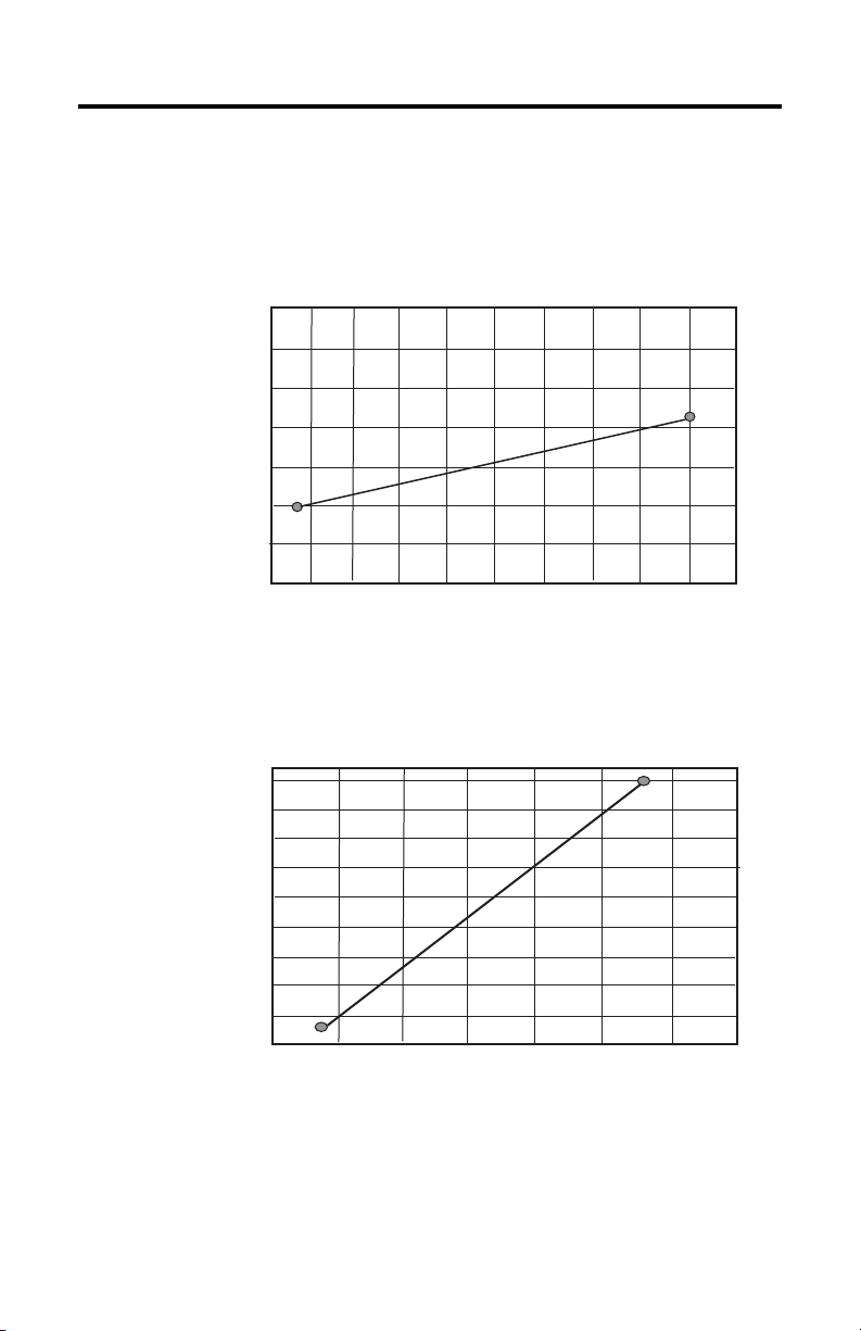
1768-PB3 Power Dissipation and Requirements
The following tables show power dissipation and input power requirements of the
1768-PB3 power supply.
1768-PB3 Power Dissipation
35 W
30 W
25 W
Power
Dissipated
(Watts)
20 W
15 W
10 W
5 W
0 W
0 W 10 W 20 W 30 W 40 W 50W 60 W 70 W 80 W 90 W
1768-PB3 Input Power
Requirements
90 W
80 W
Total Output
Power
Backplane Plus
Auxiliary
(Watts)
70 W
60 W
50 W
40 W
30 W
20 W
10 W
0 W
0 W 20 W 40 W 60 W 80 W 100 W 120 W
22 W
10 W
6 W
Output Power (Watts)
112 W
6 W
16 W
Input Power (Watts)
Publication 1768-IN001B-EN-P - July 2006
Page 11

Safety Circuits
WARNING
1768 CompactLogix Power Supplies 11
Explosion Hazard - Do not connect or disconnect connectors while circuit is
live.
ATTENTION
Circuits installed on the machine for safety reasons, like overtravel limit
switches, stop push buttons, and interlocks, should always be hard-wired
directly to the master control relay. These devices must be wired in series so
that when any one device opens, the master control relay is de-energized,
thereby removing power to the machine. Never alter these circuits to defeat
their function. Serious injury or machine damage could result.
Power Considerations
This section describes power considerations you should take into account for the
CompactLogix I/O system.
Power Distribution
The master control relay must be able to inhibit all machine motion by removing
power to the machine I/O devices when the relay is de-energized. We recommend
that the controller remain powered even when the master control relay is
de-energized.
Avoid the delay of power supply shut-down by wiring the master control relay to
remove power from the devices instead of the 1768 power supply. Power the dc
power supply directly from the fused secondary of the transformer. Connect power
to the dc input and output circuits through a set of master control relay contacts.
Publication 1768-IN001B-EN-P - July 2006
Page 12

12 1768 CompactLogix Power Supplies
Main Power Disconnect
WARNING
Explosion Hazard - Do not replace components or disconnect equipment
unless power has been switched off.
Place the main power disconnect switch where operators and maintenance
personnel have quick and easy access to it. In addition to disconnecting electrical
power, de-energize all other sources of power (pneumatic and hydraulic) before
working on a machine or process controlled by a controller.
Isolation Transformers
We recommend that you use an isolation transformer in the ac line. This type of
transformer provides isolation from your power distribution system to reduce
electrical noise and is often used as a step-down transformer to reduce line voltage.
Any transformer used with the Compact I/O system must have a sufficient power
rating for its load. The power rating is expressed in volt-amperes (VA).
Power Supply Inrush
During power-up, the power supply allows a brief inrush current to charge internal
capacitors. Many power lines and control transformers can supply inrush current
for a brief time. If the power source cannot supply this inrush current, the source
voltage may sag momentarily.
The only effect of limited inrush current and voltage sag on the system is that the
power supply capacitors charge more slowly. However, the effect of a voltage sag
on other equipment should be considered. For example, a deep voltage sag may
reset a computer connected to the same power source.
Publication 1768-IN001B-EN-P - July 2006
Page 13

1768 CompactLogix Power Supplies 13
Additional considerations determine whether the power source must be required to
supply high inrush current.
• The power-up sequence of devices in a system
• The amount of the power-source voltage sag if the inrush current cannot be
supplied
• The effect of voltage sag on other equipment in the system
If the entire system is powered-up at the same time, a brief sag in the power source
voltage typically does not affect equipment.
Loss of Power Source
The power supply is designed to withstand brief power losses without affecting the
operation of the system. The time the system is fully operational during power loss
is called the ride-through time. The duration of the ride-through time depends on
the type and state of the I/O but is typically 25 ms for the 1768-PA3 power supply
and 5 ms for the 1768-PB3 power supply. At the end of the ride-through, the power
supply’s PWR LED status indicator toggles to indicate the end of the ride-through
time.
If the power supply remains without power at the end of the ride-through time,
another period of time, the hold-up time, begins. During the hold-up time, the
power supply continues to partially power the system. The hold-up time is typically
5 ms for both power supplies.
When the duration of power loss extends beyond the hold-up time, the power
supply can no longer provide adequate dc power. At this point, the power supply
must shut down and the system performs an orderly shutdown of the controller.
During the orderly shutdown of the controller, a time period called the extended
hold-up time occurs. The extended hold-up time lasts from 8 to 12 seconds. During
this time, the power supply provides power only to the controller. The I/O,
communication, and motion modules will not receive power.
Input States on Power Down
The power supply hold-up time as described above is generally longer than the
turn-on and turn-off times of the inputs. The input-state of the controller changes
from on to off when power is removed. The controller may then record the state
before the power supply shuts down the system. This concept is important and
should be taken into account when writing the program.
Publication 1768-IN001B-EN-P - July 2006
Page 14

14 1768 CompactLogix Power Supplies
Other Types of Line Conditions
Occasionally the power source to the system can be temporarily interrupted. Also,
it is possible that the voltage level may drop substantially below the normal linevoltage range for a period of time. Both the interruption and the voltage sag are
considered power losses for the system.
Master Control Relay
A hard-wired master control relay (MCR) provides a reliable means for emergency
machine shutdown. Since the master control relay allows the placement of several
emergency-stop switches in different locations, its installation is important from a
safety standpoint. Overtravel limit switches or mushroom-head push buttons are
wired in series so that when any of them opens, the master control relay is
de-energized. Wiring this way removes power to input and output device circuits.
ATTENTION
Never alter these circuits to defeat their function since serious injury and/or
machine damage could result.
• If you are using an external dc power supply, interrupt the dc output side
rather than the ac line side of the supply to avoid the additional delay of
power supply turn-off.
• The input line of the dc output power supply should be connected to an
external fuse.
• Connect a set of master control relays in series with the dc power supplying
the input and output circuits.
Place the main power disconnect switch where operators and maintenance
personnel have quick and easy access to it. If you mount a disconnect switch inside
the enclosure, place the switch operating handle on the outside of the enclosure, so
that you can disconnect power without opening the enclosure.
When any of the emergency-stop switches are opened, remove power to input and
output devices.
When you use the master control relay to remove power from the external I/O
circuits, power continues to be provided to the system’s power supply so that
diagnostic indicators on the processor can still be observed.
Publication 1768-IN001B-EN-P - July 2006
Page 15

1768 CompactLogix Power Supplies 15
The master control relay is not a substitute for a disconnect to the system. It is
intended for any situation where the operator must quickly de-energize only I/O
devices. When inspecting or installing terminal connections, replacing output fuses,
or working on equipment within the enclosure, use the disconnect to shut off
power to the rest of the system.
Do not control the master control relay with the Compact I/O system. Provide the
operator with the safety of a direct connection between an emergency-stop switch
and the master control relay.
Periodic Tests of Master-Control Relay Circuit
Periodically test switches to assure they stop machine motion when needed.Any
part can fail, including the switches in a master-control relay circuit. The failure of
one of these switches would most likely cause an open circuit, which would be a
safe power-off failure. However, if one of these switches shorts out, it no longer
provides any safety protection.
Before You Begin
Before you begin the installation of the 1768 power supply, consider the following:
WARNING
Make sure power is disconnected from the power supply before removing
or inserting this power supply from the 1768 CompactLogix system. When
you remove or insert a power supply with power applied, an electrical arc
may occur. An electrical arc can cause personal injury or property damage
by:
• sending an erroneous signal to your system’s field devices, causing
unintended machine motion.
• causing an explosion in a hazardous environment.
Electrical arcing causes excessive wear to contacts on both the power
supply and its mating connector. Worn contacts may create electrical
resistance.
Publication 1768-IN001B-EN-P - July 2006
Page 16

16 1768 CompactLogix Power Supplies
Install the Power Supply
To install the power supply, you must complete multiple tasks.
• Mount the Power Supply
• Wire the Power Supply
• Place 1769 I/O Modules in a 1768 CompactLogix System
The 1768 CompactLogix power supply distributes power from the right side of the
supply and must be the leftmost module in the system. The maximum amount of
current the system supports on the backplane is 3.5 A at 24V dc. The maximum
amount of current the system supports externally is 0.25 A at 24V dc.
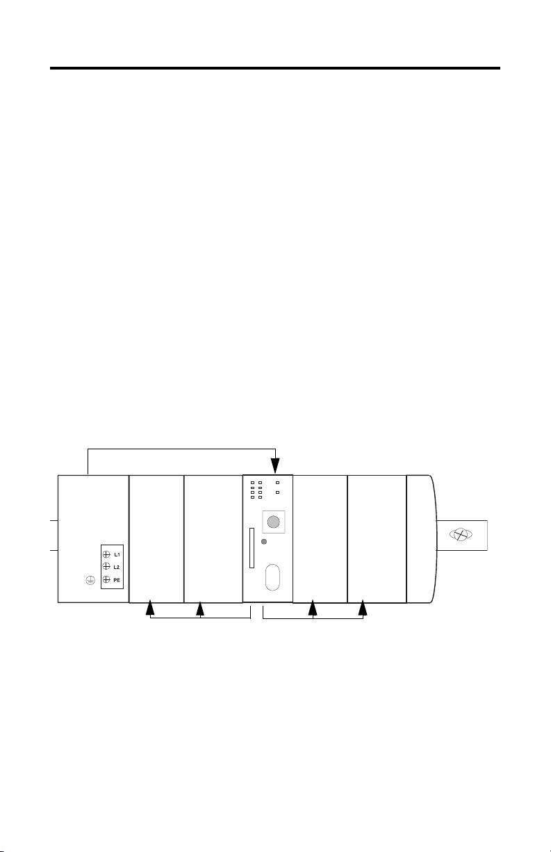
Mount the Power Supply
Before you mount the power supply, make sure you have proper spacing
and cooling.
ATTENTION
During panel or DIN rail mounting of all devices, be sure that all debris, for
example, metal chips or wire strands, is kept from falling into the module.
Debris that falls into the module could cause damage on power-up.
Maintain spacing from enclosure walls, wireways, and adjacent equipment. For
adequate ventilation allow:
• 90 mm (3.54 in.) of space to the left of the power supply.
• 90 mm (3.54 in.) of space to the right of last module in the bank.
• 105 mm (4 in.) of space on the top and bottom of the bank.
105 mm
Side
90 mm
(3.54 in.)
Top
Power Supply
1768 Communication
Module
1768 Communication
Bottom
Module
(4 in.)
Controller
105 mm
(4 in.)
1769 Compact
I/O
I/O
1769 Compact
Side
90 mm
(3.54 in.)
44024
Publication 1768-IN001B-EN-P - July 2006
Page 17

1768 CompactLogix Power Supplies 17
Prevent Excessive Heat
Convective cooling keeps the system temperature within the specified operating
range. Make sure that the specified temperature range is maintained. Proper
spacing of components within an enclosure is usually sufficient for heat dissipation.
Do not bring in unfiltered outside air. Place the CompactLogix system in an
enclosure to protect it from a corrosive atmosphere. Harmful contaminants or dirt
could cause improper operation or damage to components. In extreme cases, you
may need to use air conditioning to protect against heat build-up within the
enclosure.
Mount the Power Supply to a Panel
Mount the power supply to a panel by using four screws per module. Use M4 or #8
panhead screws though the anchors on the corners of the power supply. Mounting
screws are required on each power supply panel mounting tab.
1. Drill pilot holes in your panel.
2. Insert and tighten M4 or #8 screws through the holes in the anchors.
Tighten screws using 1.16 Nm (10 lb-in) torque.
3. If you panel-mount the entire system, connect the modules and close all DIN
rail latches in the system.
Closing the DIN rail latches locks the modules together.
Publication 1768-IN001B-EN-P - July 2006
Page 18

18 1768 CompactLogix Power Supplies
Mount the Power Supply to a DIN Rail
ATTENTION
The power supply can be mounted using the following DIN rails:
• 35 x 7.5 mm (EN 50 022 - 35 x 7.5)
• 35 x 15 mm (EN 50 022 - 35 x 15)
1. Close the DIN rail latches.
2. Press the DIN rail mounting area of the power supply against the DIN rail.
The latches will momentarily open and close, locking into place.
This product is grounded through the DIN rail to chassis ground. Use
zinc-plated yellow-chromate steel DIN rail to assure proper grounding. The use
of other DIN rail materials (for example, aluminum and plastic) that can
corrode, oxidize, or are poor conductors, can result in improper or intermittent
grounding. Secure DIN rail to mounting surface approximately every 200 mm
(7.87 in.) and use end-anchors appropriately.
The DIN rail mount of the power supply is now complete.
Publication 1768-IN001B-EN-P - July 2006
Page 19

Wire the Power Supply
1768 CompactLogix Power Supplies 19
WARNING
If you connect or disconnect wiring while the field-side power is on, an
electrical arc can occur. This could cause an explosion in hazardous location
installations. Be sure that power is removed or the area is nonhazardous before
proceeding.
Use the following instructions to wire the input terminal of your power supply
(required) and to wire the output terminal of your power supply (optional).
Wire the Input Power Terminal
Use #14 AWG 75 ° C (167 ° F) copper wire to connect input power. Use the graphic
to connect incoming power to the input power-supply terminal block.
1768-PA3 Terminal 1768-PB3 Terminal
L1 (+)
L2 (-)
Protective Earth Ground
1. Turn the screw counterclockwise to open the terminal.
2. Insert the bare wire into the terminal.
3. Turn the screw clockwise to tighten the terminal on the wire.
(+)
(-)
Protective Earth Ground
Publication 1768-IN001B-EN-P - July 2006
Page 20

20 1768 CompactLogix Power Supplies
Ground the Power Supply
ATTENTION
This product is grounded through the DIN rail to chassis ground. Use
zinc-plated yellow-chromate steel DIN rail to assure proper grounding. The
use of other DIN rail materials, for example, aluminum or plastic, that can
corrode, oxidize, or are poor conductors, can result in improper or intermittent
grounding. Secure DIN rail to mounting surface approximately every 200 mm
(7.87 in.) and use end-anchors appropriately.
Ground the power supply on a ground bus with a dedicated earth-ground stake.
The ground bus should also be connected to a functional earth ground on the DIN
rail or panel. The upper left tab on the power supply serves as a functional ground.
Ground Wiring
Power
Supply
Controller
Compact I/O
Compact I/O
Protective Earth Ground
Ground Bus
Dedicated EarthGround Stake
1768 Comm. mod.
1768 Motion mod.
Functional Ground
Refer to Industrial Automation Wiring and Grounding Guidelines, Allen-Bradley
publication 1770-4.1, for additional information.
Wire the Ground
Complete the following steps to wire the protective-earth ground:
1. Locate the protective-earth ground terminal, indicated by the following
symbol.
2. Turn the screw counterclockwise to open the terminal.
Publication 1768-IN001B-EN-P - July 2006
Page 21

1768 CompactLogix Power Supplies 21
3. Insert the bare wire into the terminal.
4. Turn the screw clockwise to tighten the terminal on the wire.
This symbol denotes a protective earth-ground that provides a low
impedance path between electrical circuits and earth for safety purposes and
provides noise immunity improvement. This connection must be made for
safety purposes.
Wire the Optional Output Power Terminal
Use #14…22 AWG 75 ° C (167 ° F) copper wire to connect the 24V dc external
power source.
Connect power to the power supply terminal block according to the graphic.
+
–
1. Turn the screw counterclockwise to open the terminal.
2. Insert the bare wire into the terminal.
3. Turn the screw clockwise to tighten the terminal on the wire.
Publication 1768-IN001B-EN-P - July 2006
Page 22

22 1768 CompactLogix Power Supplies
Place 1769 I/O Modules in a 1768 CompactLogix System
You can use up to eight 1769 I/O modules in the same bank as the 1768 power
supply. 1769 I/O modules must be placed to the right of the controller. Additional
1769 I/O modules may be placed in remote 1769 banks.
1768 System with 1769 Modules
1769 I/O Modules
(
Eight Modules, Max)
1768 Power
Supply
I/O I/O I/O
I/O
Module
Module
Communication
Communication
1768
Controller
I/O
I/O
I/O I/O
IMPORTANT
Because the 1768 CompactLogix power supply works with the controller to
power a 1768 system, the distance rating in a 1768 CompactLogix system is
different than in a 1769 CompactLogix system.
In the 1768 system, the distance rating is the distance between 1769 I/O
modules and the controller. In the 1769 system, the distance rating is the
distance between 1769 I/O modules and the power supply.
For more information on placing I/O modules in the 1768 CompactLogix system,
see the 1768 CompactLogix Controller User Manual, publication 1768-UM001.
Publication 1768-IN001B-EN-P - July 2006
Page 23

1768 CompactLogix Power Supplies 23
Interpret the LED Indicators
The CompactLogix power supply works with the CompactLogix controller to
provide power to the system. Because the power supply and controller are each
required, you must consider both when attempting to troubleshoot a power issue in
your system.
IMPORTANT
In multiple instances throughout this section, we recommend that you
disconnect, reconnect, or replace components in the 1768 CompactLogix
system. Before you disconnect, reconnect, or replace any component, make
sure you have turned off power and allowed all system status indicators to turn
off.
To troubleshoot any system power issues, use the CompactLogix power supply
PWR status indicator and the CompactLogix controller PWR and I/O PWR
status indicators. You should troubleshoot the power supply and controller status
indicators in a specific order.
1. Troubleshoot the power supply PWR status indicator.
If the power supply is not operating properly, the controller will not be
operating properly either. You must first diagnose and correct any issues
with the power supply before troubleshooting the controller.
LED Indicators
If the power
supply PWR
status
indicator is
Off One of the following:
Green The power supply is
It means Take this action
The supply is turned
off or it does not have
adequate
input
power.
A short/overload
condition exists in the
1768 system.
The supply needs to
be replaced.
operating properly.
Verify that the power supply is turned on and that adequate input
power is properly connected.
Isolate the power supply so that it is disconnected from all parts
of the system and apply power. If the indicator remains off, verify
adequate input power or consider replacing the power supply.
Replace the power supply.
No action necessary for the power supply. Check the controller
PWR and I/O PWR status indicators to make sure the entire
system is operating properly.
Publication 1768-IN001B-EN-P - July 2006
Page 24

24 1768 CompactLogix Power Supplies
If the power
supply PWR
status
indicator is
Red The power supply
It means Take this action
cannot produce valid
24V power to the
1768 modules.
A. Disconnect all modules from the system.
B. Reapply power.
C. Check the PWR status indicator.
• If the status indicator remains red, replace the power
supply.
• If the status indicator is green, one of the other modules
in the system is causing the red indicator. Move to the
next step.
D. Reinstall any 1768 motion or communication modules.
E. Reapply power.
• If the status indicator is green, either the 1768 controller
or one of the 1769 I/O modules is causing the red
indicator.
• If the status indicator remains red, one of the 1768
communication or motion modules is causing the red
indicator. Move to the next step.
F. Disconnect the 1768 communication or motion modules from
the system one at a time.
G. After each module is removed from the system, reapply
power to the power supply and check the PWR status
indicator.
• If the status indicator is green, the most
recently-removed 1768 module caused the red indicator
and should be replaced.
• If the status indicator remains red, continue
disconnecting 1768 modules one at a time until the PWR
status turns green.
2. If the power supply is operating properly, troubleshoot the controller
PWR indicator.
IMPORTANT
This step assumes the system is fully assembled and the power supply PWR
status indicator is green.
Publication 1768-IN001B-EN-P - July 2006
Page 25

1768 CompactLogix Power Supplies 25
If the
controller PWR
status
indicator is
Off Either the controller
Green The controller is
Red One of the following:
It means Take this action
or the power supply is
not operating
properly. Most likely,
in this case, the
controller has an
issue because the
power supply PWR
status indicator is
green.
operating properly
with respect to
sending power to the
1768 modules.
• The controller
needs to be
replaced.
• If 1768
communication
and motion
modules are
installed in the
system, one of
the 1768 modules
needs to be
replaced.
A. Make sure all modules in the system are installed properly
and fully engaged with each other.
B. If the controller PWR status indicator remains off, move to
the next step.
C. Remove any 1768 communication or motion modules.
D. Reinstall the controller directly next to the power supply and
reapply power.
E. If the controller PWR status indicator remains off, replace
the controller.
F. If the controller PWR status indicator on the new controller
remains off, replace the power supply.
Check the controller I/O PWR status indicator to make sure the
entire system is operating properly.
A. Disconnect all of the 1768 communication and motion
modules from the system.
B. Reapply power.
C. Check the controller PWR status indicator.
• If the status indicator is green, the controller is operating
properly and one of the other 1768 modules needs to be
replaced.
• To troubleshoot the 1768 modules, see their respective
installation instructions. For a list of related publications,
see Additional Resources.
• If the status indicator remains red, replace the controller.
Publication 1768-IN001B-EN-P - July 2006
Page 26

26 1768 CompactLogix Power Supplies
3. If the controller PWR status indicator is green, troubleshoot the controller
I/O PWR status indicator.
IMPORTANT
If the controller
I/O PWR status
indicator is
Off The controller needs to be replaced. Replace the controller.
Green The controller is operating properly. None
(1)
Red
This step assumes the power supply PWR and controller PWR
status indicators are green.
It means Take this action
One of the following:
• The controller needs to be replaced.
• If 1769 I/O modules are installed in
the system, one of the modules needs
to be replaced.
• There is a 1769 power supply
installed in the local I/O bank.
A. If there is a 1769 power supply
in the local I/O bank, remove it
and reapply power.
If the I/O PWR status indicator
remains red, move to the next
step.
B. Disconnect the 1769 I/O
modules from the system.
C. Reapply power.
D. Check the controller I/O PWR
status indicator.
• If the status indicator is
green, the controller is
operating properly and one
of the other 1769 I/O
modules needs to be
replaced.
To troubleshoot the 1769 I/O
modules, see their
respective installation
instructions.
• If the status indicator
remains red, replace the
controller.
(1)
When the controller powers up, the I/O PWR status indicator is red momentarily and then changes to green if there are no
issues. However, if the I/O PWR remains red, you should use the table to diagnose and correct any issues.
Publication 1768-IN001B-EN-P - July 2006
Page 27

1768 CompactLogix Power Supplies 27
Specifications
1768-PA3 and 1768-PB3, CompactLogix Power Supplies
Attribute 1768-PA3 1768-PB3
Efficiency 75% Typical 80% Typical @ 24V dc
Enclosure Type Rating None (open-style) None (open-style)
Input Voltage Range 85…265V ac
108…132V dc
Input Frequency Range 47…63 Hz (85…265V ac) N/A
Input Power, Max 120 VA/120 W 112 W @ 24V dc
Inrush Current, Nom 25 A @ 85…132V ac
50 A @ 195…265V ac
25 A @ 108…132V dc
Inrush Current, Max 50 A @ 85…132V ac
80 A @ 195…265V ac
North American Temp Code T4 T5
Power Dissipation, Max 30 W 22 W @ 24V dc
Isolation Voltage 250V, Reinforced Insulation Type,
input to system and 24V dc AUX,
Tested at 4250V dc for 60 s
150V, Basic Insulation Type, 24V dc
AUX to system, Tested at 2200V dc for
60 s
Internal Overcurrent
Protection
Recommended External
Overcurrent Protection
Overcurrent Protection, Max 15 A, user supplied
Wire Size, Input Power
Ter mi na l
Wire Size, Output Power
Ter mi na l
Wiring Category
Conductor Screw Torque 0.6 Nm (5 lb-in)
Dimensions (HxWxD),
Approx.
Weight, Approx. 0.98 kg (2.15 lb) 1.01 kg (2.22 lb)
Continuous Output Power
90 W, Max
Continuous Output Power
6W, Min
(1)
Non-replaceable fuse is soldered in place.
4…6 A @ 28.5…36.7 A
14 AWG (2.5 mm
greater, 1.2 mm (3/64 in.) insulation maximum
2
2.5 mm
(14 AWG )… 0.25 mm2 (22 AWG) solid or stranded copper wire rated
at 75 °C (167 °C) or greater, 1.2 mm (3/64 in.) insulation maximum
1- on power ports
131.25 x 132.75 x 105.50 mm (5.17 x 5.23 x 4.15 in.)
24V dc to backplane: 3.5 A
24V dc to user accessible terminal block: 0.25 A
24V dc to backplane: 0.25 A
24V dc to user accessible terminal block: 0.0 A
2
S 8...12 A @ 166...250 A2S
2
) solid or stranded copper wire rated at 75 °C (167°C) or
16.8-31.2V dc
30 A @ 16.8...31.2V dc
50 A @ 16.8...31.2V dc
250V, Reinforced Insulation Type,
input to system and 24V dc AUX,
Tested at 4250V dc for 60 s
150V, Basic Insulation Type, 24V dc
AUX to system, Tested at 2200V dc
for 60 s
(2)
(2)
Publication 1768-IN001B-EN-P - July 2006
Page 28

28 1768 CompactLogix Power Supplies
1768-PA3 and 1768-PB3, CompactLogix Power Supplies
Attribute 1768-PA3 1768-PB3
Output #1: 24V dc to Backplane
Ride-through
25 ms @ 90 W 5 ms @ 90 W
Interval Time, Min
Full Power Hold-up
5 ms @ 90 W
Interval
Extended Hold-up
8…12 s @ 1.25 W
Interval
Output #2: 24V dc to Front Panel Terminal Block
Voltage 18…27.60V @ front panel
Output Disable Disable output during hold-up periods
(1)
Use this Conductor Category information when planning conductor routing. Refer to Industrial Automation Wiring and
Grounding Guidelines, publication 1770-4.1.
(2)
Does not include X-capacitor charging current.
Environmental Specifications
Attribute 1768-PA3 1768-PB3
Conducted RF Immunity IEC 61000-4-6
10V rms with 1 kHz sine-wave 80% AM from 150 kHz…80 MHz
EFT/B Immunity IEC 61000-4-4:
±4kV at 5 kHz on power ports
Emissions CISPR 11:
ESD Immunity IEC 61000-4-2:
Radiated RF Immunity IEC 61000-4-3:
Relative Humidity IEC 60068-2-30 (Test Db, Unpackaged Damp Heat):
Shock, Operating IEC 60068-2-27 (Test Ea, Unpackaged Shock):
Shock, Nonoperating IEC 60068-2-27 (Test Ea, Unpackaged Shock):
Group 1, Class A
6 kV contact discharges
8 kV air discharges
• 10V/m with 1 kHz sine-wave 80%AM from 30…2000 MHz
• 10V/m with 200 Hz 50% Pulse 100%AM at 900 MHz
• 10V/m with 200 Hz 50% Pulse 100%AM at 1890 MHz
• 1V/m with 1 kHz sine-wave 80%AM from 2000…2700 MHz
5…95% noncondensing
30 g
50 g
Publication 1768-IN001B-EN-P - July 2006
Page 29

1768 CompactLogix Power Supplies 29
Environmental Specifications
Attribute 1768-PA3 1768-PB3
Surge Transient Immunity IEC 61000-4-5:
• ±2 kV line-line (DM) and ±4 kV
line-earth (CM) on ac power
ports
• ±1 kV line-line (DM) and ±2 kV
line-earth (CM) on dc power
ports
Temperature, Operating
Temperature, Storage IEC 60068-2-1 (Test Ab, Unpackaged Nonoperating Cold)
Vibration IEC 60068-2-6 (Test Fc, Operating):
Voltage Variation IEC 61000-4-11:
IEC 60068-2-1 (Test Ad, Operating Cold)
IEC 60068-2-2 (Test Bd, Operating Dry Heat)
IEC 60068-2-14 (Test Nb, Operating Thermal Shock):
0…60 °C (32…140 °F)
IEC 60068-2-2 (Test Bb, Unpackaged Nonoperating Dry Heat)
IEC 60068-2-14 (Test Na, Unpackaged Nonoperating Thermal Shock):
-40…85 °C (-40…185 °F)
5 g @ 10…500 Hz
• 30% dips for 1 period at 0° &
180° on ac supply ports
• 60% dips for 5 & 50 periods
on ac supply ports
• ±10% fluctuations for 15 min
on ac supply ports
• > 95% interruptions for 250
periods on ac supply ports
IEC 61000-4-5:
±1 kV line-line (DM) and ±2 kV
line-earth (CM) on dc power ports
IEC 61000-4-29:
• 60% dip for 100 ms on dc
supply ports
• 30% dip for 10 ms on dc
supply ports
• 100% dip for 10 ms on dc
supply ports
• ±20% fluctuations for 15 min
on dc supply ports
• 5 s interruptions on dc supply
ports
Publication 1768-IN001B-EN-P - July 2006
Page 30

30 1768 CompactLogix Power Supplies
Certifications
The following certifications apply when the product is marked.
Certifications
(1)
1768-PA3 1768-PB3
C-Tick Australian Radio Communications Act, compliant with:
AS/NZS CISPR 11; Industrial Emissions
c-UL-us UL Listed Industrial Control Equipment, certified for US and Canada. See
UL File E65584.
UL Listed for Class I, Division 2 Group A,B,C,D Hazardous Locations,
certified for U.S. and Canada. See UL File E194810.
CE Description European Union 89/336/EEC EMC
Directive, compliant with:
• EN 50082-2; Industrial
Immunity
• EN 61326;
Meas./Control/Lab., Industrial
Requirements
• EN 61000-6-2; Industrial
Immunity
• EN 61000-6-4; Industrial
Emissions
• EN 61131-2; Programmable
Controllers (Clause 8, Zone A
& B)
European Union 73/23/EEC LVD,
compliant with:
• EN 61010-1;
Meas./Control/Lab
(1)
See the Product Certification link at http://www.ab.com for Declarations of Conformity, Certificates, and other certification
details.
European Union 89/336/EEC EMC
Directive, compliant with:
• EN 50082-2; Industrial
Immunity
• EN 61326;
Meas./Control/Lab., Industrial
Requirements
• EN 61000-6-2; Industrial
Immunity
• EN 61000-6-4; Industrial
Emissions
• EN 61131-2; Programmable
Controllers (Clause 8, Zone A
& B)
• European Union 73/23/EEC
LVD, compliant with:
• EN 61010-1;
Meas./Control/Lab
Publication 1768-IN001B-EN-P - July 2006
Page 31

1768 CompactLogix Power Supplies 31
Additional Resources
Consult the following publications as sources of additional information.
For Refer to this document Pub. No.
A description of how to use your
CompactLogix controller
A description of how to use your
CompactLogix EtherNet/IP module
A description of how to use your CompactLogix
SERCOS interface module
A description of Compact I/O modules Compact I/O Selection Guide 1769-SG002
More information on proper wiring and
grounding techniques
1768 CompactLogix Controllers
Installation Instructions
1768 CompactLogix Controllers
User Manual
CompactLogix EtherNet/IP
Communication Module
Installation Instructions
CompactLogix EtherNet/IP
Communication Module
User Manual
CompactLogix SERCOS interface
Module Installation Instructions
Motion Modules in Logix5000
Control Systems User Manual
Industrial Automation Wiring and
Grounding Guidelines
1768-IN004
1768-UM001
1768-IN002
ENET-UM001
1768-IN005
LOGIX-UM002
1770-4.1
You can view or download publications at
http://literature.rockwellautomation.com
. To order paper copies of technical
documentation, contact your local Rockwell Automation distributor or sales
representative.
CompactLogix is a registered trademark of Rockwell Automation, Inc.
Trademarks not belonging to Rockwell Automation are property of their respective companies.
Publication 1768-IN001B-EN-P - July 2006
Page 32

Rockwell Automation Support
Rockwell Automation provides technical information on the Web to assist you in
using its products. At http://support.rockwellautomation.com
technical manuals, a knowledge base of FAQs, technical and application notes,
sample code and links to software service packs, and a MySupport feature that you
can customize to make the best use of these tools.
For an additional level of technical phone support for installation, configuration,
and troubleshooting, we offer TechConnect Support programs. For more
information, contact your local distributor or Rockwell Automation representative,
or visit http://support.rockwellautomation.com
.
Installation Assistance
If you experience a problem with a hardware module within the first 24 hours of
installation, please review the information that's contained in this manual. You can
also contact a special Customer Support number for initial help in getting your
module up and running.
, you can find
United States 1.440.646.3223
Outside United
States
Monday – Friday, 8am – 5pm EST
Please contact your local Rockwell Automation representative for any
technical support issues.
New Product Satisfaction Return
Rockwell tests all of its products to ensure that they are fully operational when
shipped from the manufacturing facility. However, if your product is not
functioning, it may need to be returned.
United States Contact your distributor. You must provide a Customer Support case number
Outside United
States
Publication 1768-IN001B-EN-P - July 2006 PN 953014-45
Supersedes Publication 1768-IN001A-EN-P - December 2005 Copyright © 2006 Rockwell Automation, Inc. All rights reserved. Printed in the U.S.A.
(see phone number above to obtain one) to your distributor in order to
complete the return process.
Please contact your local Rockwell Automation representative for return
procedure.
 Loading...