

Page 1

Installation Instructions
CompactLogix SERCOS interface Module
Catalog Number 1768-M04SE
Contents
For See Page
Important User Information 2
Environment and Enclosure 3
Prevent Electrostatic Discharge 4
North American Hazardous Location Approval 5
Catalog Number Explanation 7
Product Dimensions 7
Minimum Spacing 8
What You Need 9
Choose Your Fiber Optic Cables 9
Install Your Modules 12
Remove a Module 19
Care of Fiber Optic Cables 20
Troubleshoot the Module 21
Specifications 23
Additional Resources 27
Rockwell Automation Support BackCover
Publication 1768-IN005A-EN-P - December 2005
Page 2
2
Important User Information
Solid state equipment has operational characteristics differing from those of electromechanical
equipment. Safety Guidelines for the Application, Installation and Maintenance of Solid State Controls
(Publication SGI-1.1 available from your local Rockwell Automation sales office or online at
http://www.literature.rockwellautomation.com) describes some important differences between solid
state equipment and hard-wired electromechanical devices. Because of this difference, and also
because of the wide variety of uses for solid state equipment, all persons responsible for applying this
equipment must satisfy themselves that each intended application of this equipment is acceptable.
In no event will Rockwell Automation, Inc. be responsible or liable for indirect or consequential damages
resulting from the use or application of this equipment.
The examples and diagrams in this manual are included solely for illustrative purposes. Because of the
many variables and requirements associated with any particular installation, Rockwell Automation, Inc.
cannot assume responsibility or liability for actual use based on the examples and diagrams.
No patent liability is assumed by Rockwell Automation, Inc. with respect to use of information, circuits,
equipment, or software described in this manual.
Reproduction of the contents of this manual, in whole or in part, without written permission of Rockwell
Automation, Inc., is prohibited.
Throughout this manual, when necessary, we use notes to make you aware of safety considerations.
WARNING
Identifies information about practices or circumstances that can cause an explosion in
a hazardous environment, which may lead to personal injury or death, property
damage, or economic loss.
IMPORTANT
ATTENTION
SHOCK HAZARD
BURN HAZARD
Publication
Identifies information that is critical for successful application and understanding of
the product.
Identifies information about practices or circumstances that can lead to personal
injury or death, property damage, or economic loss. Attentions help you to identify a
hazard, avoid a hazard, and recognize the consequences.
Labels may be located on or inside the equipment, for example, a drive or motor, to
alert people that dangerous voltage may be present.
Labels may be located on or inside the equipment, for example, a drive or motor, to
alert people that surfaces may be dangerous temperatures.
1768-IN005A-EN-P - December 2005
Page 3

Environment and Enclosure
3
ATTENTION
This equipment is intended for use in a Pollution Degree
2 industrial environment, in overvoltage Category II
applications (as defined in IEC publication 60664-1), at
altitudes up to 2000 meters without derating.
This equipment is considered Group 1, Class A industrial
equipment according to IEC/CISPR Publication 11.
Without appropriate precautions, there may be potential
difficulties ensuring electromagnetic compatibility in other
environments due to conducted as well as radiated
disturbance.
This equipment is supplied as open-type equipment. It
must be mounted within an enclosure that is suitably
designed for those specific environmental conditions that
will be present and appropriately designed to prevent
personal injury resulting from accessibility to live parts.
The enclosure must have suitable flame-retardant
properties to prevent or minimize the spread of flame,
complying with a flame spread rating of 5VA, V2, V1, V0
(or equivalent) if non-metallic. The interior of the
enclosure must be accessible only by the use of a tool.
Subsequent sections of this publication may contain
additional information regarding specific enclosure type
ratings that are required to comply with certain product
safety certifications.
Besides this publication, see:
• Allen-Bradley publication 1770-4.1, Industrial
Automation Wiring and Grounding Guidelines, for
additional installation requirements.
• NEMA Standards publication 250 and IEC publication
60529, as applicable, for explanations of the degrees
of protection provided by different types of
enclosure.
Publication
1768-IN005A-EN-P - December 2005
Page 4

4
Prevent Electrostatic Discharge
ATTENTION
This equipment is sensitive to electrostatic discharge,
which can cause internal damage and affect normal
operation. Follow these guidelines when you handle this
equipment:
• Touch a grounded object to discharge potential static.
• Wear an approved grounding wriststrap.
• Do not touch connectors or pins on component
boards.
• Do not touch circuit components inside the
equipment.
• If available, use a static-safe workstation.
• When not in use, store the equipment in appropriate
static-safe packaging.
Publication
1768-IN005A-EN-P - December 2005
Page 5
5
North American Hazardous Location Approval
The following information applies when operating this
equipment in hazardous locations:
Products marked “CL I, DIV 2, GP A, B, C, D” are suitable for use in
Class I Division 2 Groups A, B, C, D, Hazardous Locations and
nonhazardous locations only. Each product is supplied with markings
on the rating nameplate indicating the hazardous location
temperature code. When combining products within a system, the
most adverse temperature code (lowest “T” number) may be used to
help determine the overall temperature code of the system.
Combinations of equipment in your system are subject to
investigation by the local Authority Having Jurisdiction at the time of
installation.
WARNING
EXPLOSION HAZARD
• Do not disconnect equipment unless power has been
removed or the area is known to be nonhazardous.
• Do not disconnect connections to this equipment
unless power has been removed or the area is
known to be nonhazardous. Secure any external
connections that mate to this equipment by using
screws, sliding latches, threaded connectors, or other
means provided with this product.
• Substitution of components may impair suitability for
Class I, Division 2.
• If this product contains batteries, they must only be
changed in an area known to be nonhazardous.
Publication
1768-IN005A-EN-P - December 2005
Page 6
6
Informations sur l'utilisation de cet équipement en
environnements dangereux:
Les produits marqués “CL I, DIV 2, GP A, B, C, D” ne conviennent
qu'à une utilisation en environnements de Classe I Division 2
Groupes A, B, C, D dangereux et non dangereux. Chaque produit est
livré avec des marquages sur sa plaque d'identification qui indiquent
le code de température pour les environnements dangereux. Lorsque
plusieurs produits sont combinés dans un système, le code de
température le plus défavorable (code de température le plus faible)
peut être utilisé pour déterminer le code de température global du
système. Les combinaisons d'équipements dans le système sont
sujettes à inspection par les autorités locales qualifiées au moment de
l'installation.
AVERTISSEMENT
Publication
RISQUE D'EXPLOSION
• Couper le courant ou s'assurer que
l'environnement est classé non dangereux avant
de débrancher l'équipement.
• Couper le courant ou s'assurer que
l'environnement est classé non dangereux avant
de débrancher les connecteurs. Fixer tous les
connecteurs externes reliés à cet équipement à
l'aide de vis, loquets coulissants, connecteurs
filetés ou autres moyens fournis avec ce produit.
• La substitution de composants peut rendre cet
équipement inadapté à une utilisation en
environnement de Classe I, Division 2.
• S'assurer que l'environnement est classé non
dangereux avant de changer les piles.s
1768-IN005A-EN-P - December 2005
Page 7
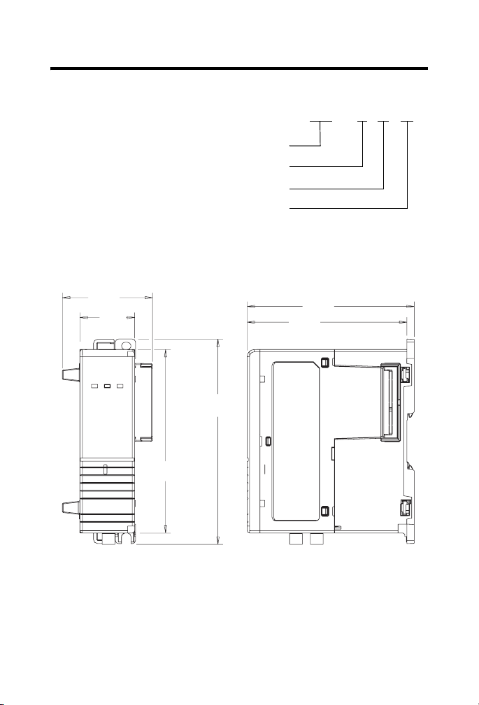
Catalog Number Explanation
Use this module with a 1768 CompactLogix controller
Use this module for motion control
Control up to 4 drives
Control SERCOS interface drives
Product Dimensions
7
1768 - M 04 SE
56.68 mm
(2.23 in.)
34.5 mm
(1.36 in.)
118 mm
(4.65 in.)
132.015 mm
(5.2 in.)
Publication
105.1 mm
(4.14 in.)
100.5 mm
(3.96 in.)
1768-IN005A-EN-P - December 2005
Page 8
8
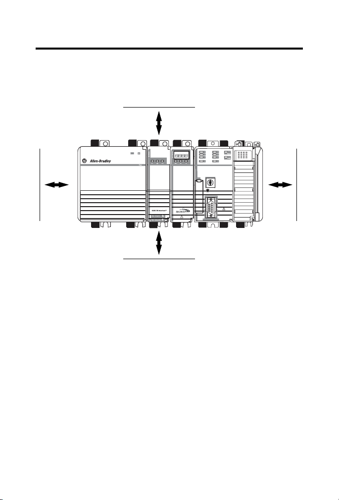
Minimum Spacing
Plan for this minimum spacing from enclosure walls, wireways, and
other equipment.
105 mm (4 in.)
90 mm
(3.54 in.)
Publication
90 mm
(3.54 in.)
105 mm (4 in.)
1768-IN005A-EN-P - December 2005
Page 9
What You Need
9
IMPORTANT
This product is grounded through the DIN rail to chassis
ground. Use zinc plated yellow-chromate steel DIN rail
to assure proper grounding. The use of other DIN rail
materials (e.g. aluminum, plastic, etc.) that can corrode,
oxidize, or are poor conductors, can result in improper
or intermittent grounding. Secure DIN rail to mounting
surface approximately every 200 mm (7.87 in.) and use
end-anchors appropriately.
Item Catalog Number or Size
1768 CompactLogix power supply 1768-PA3
1768 CompactLogix controller 1768-L43
1769 end cap
fiber optic cables See Choose Your Fiber Optic Cables.
DIN rail or mounting screws (one
or the other but not both)
(1)
(1)
You need a 1769-ECR end cap even if you aren’t using any 1769 I/O modules. Put it on the
right side of the controller.
1769-ECR
DIN rail Either of these sizes:
• 35 x 7.5 mm (EN 50022 - 35 x 7.5)
• 35 x 15 mm (EN 50022 - 35 x 15)
screws M4 or #8 panhead screws
Choose Your Fiber Optic Cables
For This Distance Then See Page
Up to 32 m (105 ft) Choose a Plastic Fiber Optic Cable 10
More than 32 m (105 ft) Choose a Glass Fiber Optic Cable 11
Publication
1768-IN005A-EN-P - December 2005
Page 10

10
Choose a Plastic Fiber Optic Cable
For Use In Use This Type of
Electrical cabinet Non-jacketed
Normal
environments
outside of an
electrical cabinet
Plastic Cable
(chlorinated
polyethylene)
Standard jacket
(polyvinyl chloride)
Length Allen-Bradley
Catalog Number
0.1 m (5.1 in.) 2090-SCEP0-1
0.2 m (7 in.) 2090-SCEP0-2
0.3 m (1 ft) 2090-SCEP0-3
1 m (3.2 ft) 2090-SCEP1-0
3 m (9.8 ft) 2090-SCEP3-0
5 m (16.4 ft) 2090-SCEP5-0
8 m (26.2 ft) 2090-SCEP8-0
10 m (32.8 ft) 2090-SCEP10-0
15 m (49.2 ft) 2090-SCEP15-0
20 m (65.5 ft) 2090-SCEP20-0
25 m (82 ft) 2090-SCEP25-0
32 m (105 ft) 2090-SCEP32-0
0.1 m (4 in.) 2090-SCVP0-1
0.3 m (1 ft) 2090-SCVP0-3
0.9 m (2.9 ft) 2090-SCVP0-9
1 m (3.2 ft) 2090-SCVP1-0
3 m (9.8 ft) 2090-SCVP3-0
5 m (16.4 ft) 2090-SCVP5-0
8 m (26.2 ft) 2090-SCVP8-0
10 m (32.8 ft) 2090-SCVP10-0
15 m (49.2 ft) 2090-SCVP15-0
20 m (65.5 ft) 2090-SCVP20-0
25 m (82 ft) 2090-SCVP25-0
32 m (105 ft) 2090-SCVP32-0
Publication
1768-IN005A-EN-P - December 2005
Page 11

11
For Use In Use This Type of
Plastic Cable
Harsh environment Nylon jacketed 0.1 m (4 in.) 2090-SCNP0-1
Length Allen-Bradley
Catalog Number
0.3 m (1 ft) 2090-SCNP0-3
0.9 m (2.9 ft) 2090-SCNP0-9
1 m (3.2 ft) 2090-SCNP1-0
3 m (9.8 ft) 2090-SCNP3-0
5 m (16.4 ft) 2090-SCNP5-0
8 m (26.2 ft) 2090-SCNP8-0
10 m (32.8 ft) 2090-SCNP10-0
15 m (49.2 ft) 2090-SCNP15-0
20 m (65.5 ft) 2090-SCNP20-0
25 m (82 ft) 2090-SCNP25-0
32 m (105 ft) 2090-SCNP32-0
Choose a Glass Fiber Optic Cable
These cables have a polyvinyl chloride jacket for use in normal
environments
Length Allen-Bradley Catalog Number
50 m (164.2 ft) 2090-SCVG50-0
100 m (328.3 ft) 2090-SCVG100-0
150 m (492.5 ft) 2090-SCVG150-0
200 m (656.7 ft) 2090-SCVG200-0
.
Publication
1768-IN005A-EN-P - December 2005
Page 12

12
Install Your Modules
IMPORTANT
Do not use both screws and DIN rail to mount the
modules. It is possible to break the mounting tabs off if
you screw the modules to the panel while they are on
DIN rail.
If You Are Using Screws to Mount Your Modules
The steps in these instructions show how to mount the modules on
DIN rail. If you are using screws instead of DIN rail, make these
changes to the instructions:
1. Follow the steps in Mount the Modules on the DIN Rail to
connect the modules together.
2. Use the modules as a template and mark pilot holes on your
panel.
3. Drill the pilot holes for M4 or #8 screws.
4. Use M4 or #8 screws to mount the modules to your panel.
Install the DIN Rail
Publication
1768-IN005A-EN-P - December 2005
Page 13

Mount the Modules on the DIN Rail
1
2
13
31595-M
Publication
31596 -M
1768-IN005A-EN-P - December 2005
Page 14

14
Mount the Modules on the DIN Rail — Continued
3
31597-M
4
Publication
b
b
c
c
1768-IN005A-EN-P - December 2005
a
a
31598 -M
Page 15

Mount the Modules on the DIN Rail — Continued
5
15
6 a
Publication
1768-IN005A-EN-P - December 2005
a
d
b
b
c
c
d
31600-M
Page 16

16
Mount the Modules on the DIN Rail — Continued
7
b
b
c
c
a
a
Publication
1768-IN005A-EN-P - December 2005
Page 17

Connect the Fiber Optic Cables
17
ATTENTION
Under certain conditions, viewing the optical port may
expose the eye to hazard. When viewed under some
conditions, the optical port may expose the eye beyond
the maximum permissible exposure recommendations.
SERVO
Interface
b
a
a
b
c
c
Publication
31604-M
1768-IN005A-EN-P - December 2005
Page 18

18
Confirm Your Installation
Flashing Green
Flashing Red and
Flashing Green
Green
Power
L1
L2/N
OUT
31608-M
See Troubleshoot the Module on page 21 if the lights are in other
states.
Publication
1768-IN005A-EN-P - December 2005
Page 19

Remove a Module
1
19
c — Off
Power
L1
L2/N
b — Off
d
OUT
f
a
e
2
Power
L1
L2/N
a
a
OUT
c
c
31602-M
31607-M
b
b
Publication
1768-IN005A-EN-P - December 2005
Page 20

20
Why Wait for the Lights to Turn Off Before I Remove a Module?
After you turn off the power, wait for all of the lights on the power
supply and controller to turn off before you disconnect any modules.
• When you turn off the power, the controller writes its project
to Flash memory.
• The MEM SAVE light turns on while the controller writes its
project to Flash memory.
• If you don’t wait for the lights to turn off, you will lose your
project.
Care of Fiber Optic Cables
Keep the fiber optic ports clean. Dirt and dust block the optic path
and reduce performance.
• Cap the ports and cables when you aren’t using them.
• Clean the ends of the cables with either:
– compressed air
– lint and strand free cotton swab and one of these cleaners:
Alcohols Aliphatics Other
methyl hexane soap solution
isopropyl heptane naphtha
isobutyl
For more information, see Fiber Optic Cable Installation and
Handling Instructions, publication number 2090-IN010.
Publication
1768-IN005A-EN-P - December 2005
Page 21

Troubleshoot the Module
21
SERCOS Phase
SERCOS Ring Status
Module Status
If the lights on the module
look like this
CP Ring OK
Off Off Off • Make sure the module is connected and locked to the
Off Off Flashing
Flashing
Orange
Solid
Orange
Flashing
Red and
Green
Off Flashing
Flashing
Red
Flashing
Green
Red
Green
Flashing
Green
Flashing
Green
Then do this
other modules.
• Check the power supply and controller to make sure
the backplane has power.
Wait! Someone is updating the firmware of the module.
• Look for cables that are broken, unplugged, or in the
wrong port.
• Check the drives for faults.
• Make sure each drive has its own address.
• Make sure that all of the drives have the same baud
rate.
• Set the Data Rate of the SERCOS interface module to
Auto-Detect.
• Check the Cycle Time of the SERCOS interface
module. See
Did you configure the module?
• NO — Use RSLogix 5000 software to configure the
module.
• YES — Check the configuration of the module and
drives in RSLogix 5000 software.
Specifications on page 23.
Publication
1768-IN005A-EN-P - December 2005
Page 22

22
If the lights on the module
look like this
CP Ring OK
Flashing
Green
Solid
Green
Solid
Green
Solid
Green
Solid
Red
Flashing
Green
Solid
Green
Solid
Green
Solid
Green
Solid
Red
Flashing
Green
Flashing
Green
Solid
Green
Flashing
Red
Solid
Red
Then do this
Check the configuration of the axes in RSLogix 5000
software.
• Check the configuration of the drives in RSLogix 5000
software.
• Check the motion group, drives, and axes for faults.
None — the axes are ready.
Check the motion group and axes for faults.
1. Cycle power to the module.
2. If the lights keep turning solid red, contact your
distributor, Rockwell Automation
representative, or Rockwell Automation
support.
Publication
1768-IN005A-EN-P - December 2005
Page 23

Specifications
CompactLogix SERCOS interface Module - 1768-M04SE
Attribute Valu e
Backplane Current (mA) 969 mA @ 5.2V dc
Connections Consumed 3
Dimensions (HxWxD),
Metric, Approx.
Dimensions (HxWxD),
Imperial, Approx.
Fiber Optic Bend Radius Plastic cable without a jacket — 25 mm (0.98 in.)
Fiber Optic Cable
Attenuation
Fiber Optic Cladding
Diameter
Fiber Optic Connector F-SMA standard screw-type connector
Fiber Optic Core
Diameter
Fiber Optic Operating
Temperature
Overall — 132.015 x 56.68 x 105.1 mm
Installed and including mounting tabs —
132.015
x 34.5 x 105.1 mm
Installed but not including mounting tabs —
118
x 34.5 x 105.1 mm
Overall — 5.2 x 2.23 x 4.14 in.
Installed and including mounting tabs — 5.2 x 1.36 x 4.14 in.
Installed but not including mounting tabs —
4.65
x 1.36 x 4.14 in.
Plastic cable with a standard jacket — 25 mm (0.98 in.)
Plastic cable with a nylon jacket — 40 mm (1.6 in.)
Glass cable — 30 mm (1.2 in.)
Plastic cable — 140 dB/km @ 650 nm
Glass cable — 6.0 dB/km @ 820 nm
Plastic cable — 1000 µm ± 60 µm
Glass cable — 230 µm +0/-10 µm
Plastic cable — 980 µm ± 60 µm
Glass cable — 200 µm ± 4 µm
Plastic cable — -55…85 °C
Glass cable — -20…85 °C
23
Publication
1768-IN005A-EN-P - December 2005
Page 24

24
CompactLogix SERCOS interface Module - 1768-M04SE (Continued)
Attribute Value
Fiber Optic Transmission
Range
Mounting Screw Torque 1.16 Nm (10 lb-in.), using M4 or #8 screws
Number of Axes, per
Module, Max.
Power Dissipation 5.04 W
Power Supply Distance
Rating
SERCOS Class Class B (Position or Velocity)
SERCOS Data Rate 4 M or 8 M
SERCOS Operating Cycle Important: Only Kinetix 6000 drives let you use a 0.5 ms Cycle
Weight, Imperial 7.11 oz
Weight, Metric 0.20 kg
North American Temp
Code
Plastic cable — 1…32 m
Glass cable — 1…200 m
4 drives and 2 auxiliary feedback axes
2 — Keep the module within 2 slots from the power supply.
Tim e.
• 4 M Data Rate and up to 2 drives — 0.5 ms Cycle
Tim e
• 4 M Data Rate and up to 4 drives — 1 ms Cycle Time
• 8 M Data Rate and up to 4 drives — 0.5 ms Cycle
Tim e
T4A
Environmental Specifications
Attribute Valu e
Operating Temperature IEC 60068-2-1 (Test Ad, Operating Cold),
IEC 60068-2-2 (Test Bd, Operating Dry Heat),
IEC 60068-2-14 (Test Nb, Operating Thermal Shock):
Publication
1768-IN005A-EN-P - December 2005
Page 25

Environmental Specifications (Continued)
Attribute Value
0…60 °C (32…140 °F)
Non-Operating Temperature IEC 60068-2-1 (Test Ab, Un-packaged Non-operating Cold),
IEC 60068-2-2 (Test Bb, Un-packaged Non-operating Dry
Heat),
IEC 60068-2-14 (Test Na, Un-packaged Non-operating
Thermal Shock):
-40…85 °C (-40…185 °F)
Relative Humidity IEC 60068-2-30 (Test Db, Un-packaged Damp Heat):
5…95% non-condensing
Vibration IEC 60068-2-6 (Test Fc, Operating):
5 g @ 10…500 Hz
Operating Shock IEC 60068-2-27 (Test Ea, Unpackaged Shock):
30 g
Non-Operating Shock IEC 60068-2-27 (Test Ea, Unpackaged Shock):
50 g
Emissions CISPR 11:
Group 1, Class A
ESD Immunity IEC 61000-4-2:
4 kV contact discharges
8 kV air discharges
25
Publication
1768-IN005A-EN-P - December 2005
Page 26

26
Environmental Specifications (Continued)
Attribute Value
Radiated RF Immunity IEC 61000-4-3:
10V/m with 1 kHz sine-wave 80%AM from 30…2000 MHz
10V/m with 200 Hz 50% Pulse 100%AM at 900 MHz
10V/m with 200 Hz 50% Pulse 100%AM at 1890 MHz
1V/m with 1 kHz sine-wave 80%AM from 2000…2700 MHz
Enclosure Type Rating None (open-style)
Certifications
These certifications apply when the product is marked with them. See
the Product Certification link at www.ab.com for Declarations of
Conformity, Certificates, and other certification details.
Certification Value
c-UL-us UL Listed Industrial Control Equipment, certified for US and Canada.
See UL File E65584.
UL Listed for Class I, Division 2 Group A,B,C,D Hazardous Locations,
certified for U.S. and Canada. See UL File E194810.
CE European Union 89/336/EEC EMC Directive, compliant with:
EN 50082-2; Industrial Immunity
EN 61326; Meas./Control/Lab., Industrial Requirements
EN 61000-6-2; Industrial Immunity
EN 61000-6-4; Industrial Emissions
EN 61131-2; Programmable Controllers (Clause 8, Zone A & B)
C-Tick Australian Radiocommunications Act, compliant with:
AS/NZS CISPR 11; Industrial Emissions
Publication
1768-IN005A-EN-P - December 2005
Page 27

Additional Resources
Publication Publication Number
1768 CompactLogix Power Supplies Installation
Instructions
CompactLogix Controller Installation Instructions 1768-IN004
CompactLogix EtherNet/IP Communication Module
Installation Instructions
CompactLogix Controllers User Manual 1768-UM001
Motion Modules in Logix5000 Control Systems User
Manual
Logix5000 Controller Motion Instructions Reference
Manual
1394 SERCOS Interface Multi Axis Motion Control
System Installation Manual
1394 SERCOS Integration Manual 1394-IN024
Ultra3000 Digital Servo Drives Installation Manual 2098-IN003
Ultra3000 Digital Servo Drives Integration Manual 2098-IN005
Kinetix 6000 Installation Manual 2094-IN001
Kinetix 6000 Integration Manual 2094-IN002
8720MC High Performance Drive Installation Manual 8720MC-IN001
8720MC High Performance Drive Integration Manual 8720MC-IN002
1768-IN001
1768-IN002
LOGIX-UM002
1756-RM007
1394-IN002
27
Allen-Bradley, CompactLogix, Kinetix, Logix5000, and Ultra3000 are trademarks of Rockwell
Automation, Inc.
Trademarks not belonging to Rockwell Automation are property of their respective companies.
Publication
1768-IN005A-EN-P - December 2005
Page 28

Rockwell Automation Support
Rockwell Automation provides technical information on the web to assist you
in using its products. At http://support.rockwellautomation.com, you can find
technical manuals, a knowledge base of FAQs, technical and application
notes, sample code and links to software service packs, and a MySupport
feature that you can customize to make the best use of these tools.
For an additional level of technical phone support for installation,
configuration and troubleshooting, we offer TechConnect Support programs.
For more information, contact your local distributor or Rockwell Automation
representative, or visit http://support.rockwellautomation.com.
Installation Assistance
If you experience a problem with a hardware module within the first 24 hours
of installation, please review the information that’s contained in this manual.
You can also contact a special Customer Support number for initial help in
getting your module up and running:
United States 1.440.646.3223 Monday – Friday, 8am – 5pm EST
Outside United States Please contact your local Rockwell Automation representative for any
New Product Satisfaction Return
Rockwell tests all of its products to ensure that they are fully operational when
shipped from the manufacturing facility. However, if your product is not
functioning and needs to be returned:
United States Contact your distributor. You must provide a Customer Support case number
Outside United States Please contact your local Rockwell Automation representative for return
Back Cover
Publication 1768-IN005A-EN-P - December 2005 PN 957988-33
Supersedes Publication - Copyright © 2005 Rockwell Automation, Inc. All rights reserved. Printed in the U.S.A.
technical support issues.
(see phone number above to obtain one) to your distributor in order to
complete the return process.
procedure.
ö
 Loading...