

Rockwell Automation CompactLogix series, 1768-L45S, 1768-L43S, 1768-L43, 1768-L45 Installation Instructions Manual
Installation Instructions
CompactLogix Controllers
Catalog Numbers 1768-L43, 1768-L43S, 1768-L45, 1768-L45S
Topic Page
Important User Information 2
About CompactLogix Controllers 6
Verify Compatibility 6
Required System Components 7
Clearance Requirements 7
Module Placement 8
Install the Controller 9
Panel Mount the Controller 10
Mount the Controller on a DIN Rail 10
Confirm the Installation 13
Connect to the Controller 14
Configure a Communication Driver 14
Insert or Remove a CompactFlash Card 18
Install Controller Firmware 18
Remove a 1768 or 1769 Module from the DIN Rail 21
Status Indicators 23
Safety Status Indicators (1768-L43S and 1768-L45S Controllers only) 25
Clear a Major Fault 26
Clear a Nonrecoverable Fault 27
Troubleshoot a Nonresponsive Module 27
Troubleshoot System Power 28
Specifications 32
Additional Resources 36
2 CompactLogix Controllers
Important User Information
Solid state equipment has operational characteristics differing from those of electromechanical
equipment. Safety Guidelines for the Application, Installation and Maintenance of Solid State Controls
(publication SGI-1.1
http://literature.rockwellautomation.com
equipment and hard-wired electromechanical devices. Because of this difference, and also because of
the wide variety of uses for solid state equipment, all persons responsible for applying this equipment
must satisfy themselves that each intended application of this equipment is acceptable.
In no event will Rockwell Automation, Inc. be responsible or liable for indirect or consequential damages
resulting from the use or application of this equipment.
The examples and diagrams in this manual are included solely for illustrative purposes. Because of the
many variables and requirements associated with any particular installation, Rockwell Automation, Inc.
cannot assume responsibility or liability for actual use based on the examples and diagrams.
No patent liability is assumed by Rockwell Automation, Inc. with respect to use of information, circuits,
equipment, or software described in this manual.
available from your local Rockwell Automation sales office or online at
) describes some important differences between solid state
Reproduction of the contents of this manual, in whole or in part, without written permission of Rockwell
Automation, Inc., is prohibited.
Throughout this manual, when necessary, we use notes to make you aware of safety considerations.
WARNING
IMPORTANT
ATTENTION
SHOCK HAZARD
Identifies information about practices or circumstances that can cause an explosion in
a hazardous environment, which may lead to personal injury or death, property
damage, or economic loss.
Identifies information that is critical for successful application and understanding of
the product.
Identifies information about practices or circumstances that can lead to personal
injury or death, property damage, or economic loss. Attentions help you identify a
hazard, avoid a hazard and recognize the consequences.
Labels may be on or inside the equipment, for example, drive or motor, to alert people
that dangerous voltage may be present.
BURN HAZARD
Publication
Labels may be on or inside the equipment, for example, drive or motor, to alert people
that surfaces may reach dangerous temperatures.
1768-IN004D-EN-P - December 2009

Environment and Enclosure
CompactLogix Controllers 3
ATTENTION
This equipment is intended for use in a Pollution Degree 2 industrial environment,
in overvoltage Category II applications (as defined in IEC publication 60664-1), at
altitudes up to 2000 m (6562 ft) without derating.
This equipment is considered Group 1, Class A industrial equipment according to
IEC/CISPR Publication 11. Without appropriate precautions, there may be
difficulties with electromagnetic compatibility in residential and other
environments due to conducted as well as radiated disturbances.
This equipment is supplied as open-type equipment. It must be mounted within
an enclosure that is suitably designed for those specific environmental
conditions that will be present and appropriately designed to prevent personal
injury resulting from accessibility to live parts. The enclosure must have suitable
flame-retardant properties to prevent or minimize the spread of flame, complying
with a flame spread rating of 5VA, V2, V1, V0 (or equivalent) if non-metallic. The
interior of the enclosure must be accessible only by the use of a tool. Subsequent
sections of this publication may contain additional information regarding specific
enclosure type ratings that are required to comply with certain product safety
certifications.
In addition to this publication, see:
• Industrial Automation Wiring and Grounding Guidelines, Rockwell
Automation publication 1770-4.1
requirements.
, for additional installation
• NEMA Standards 250 and IEC 60529, as applicable, for explanations of
the degrees of protection provided by different types of enclosure.
Publication
1768-IN004D-EN-P - December 2009
4 CompactLogix Controllers
European Hazardous Location Approval
Consider the following if you install a 1768-L43S or 1768-L45S
controller in a European Zone 2 location.
European Zone 2 Certification (The following applies when the product bears the
EX marking.)
This equipment is intended for use in potentially explosive atmospheres as defined by
European Union Directive 94/9/EC and has been found to comply with the Essential Health
and Safety Requirements relating to the design and construction of Category 3 equipment
intended for use in Zone 2 potentially explosive atmospheres, given in Annex II to this
Directive.
Compliance with the Essential Health and Safety Requirements has been assured by
compliance with EN 60079-15 and EN 60079-0.
WARNING
• This equipment must be installed in an enclosure providing at least IP54
protection when applied in Zone 2 environments.
• This equipment shall be used within its specified ratings defined by
Allen-Bradley.
• Provision shall be made to prevent the rated voltage from being
exceeded by transient disturbances of more than 40% when applied in
Zone 2 environments.
• This equipment is not resistant to sunlight or other sources of UV
radiation.
• Secure any external connections that mate to this equipment by using
screws, sliding latches, threaded connectors, or other means provided
with this product.
• Do not disconnect equipment unless power has been removed or the
area is known to be nonhazardous.
General Safety Information for 1768-L43S and 1768-L45S Controllers
ATTENTION
Publication
Personnel responsible for the application of safety-related programmable
electronic systems (PES) shall be aware of the safety requirements in the
application of the system and shall be trained in using the system.
1768-IN004D-EN-P - December 2009
CompactLogix Controllers 5
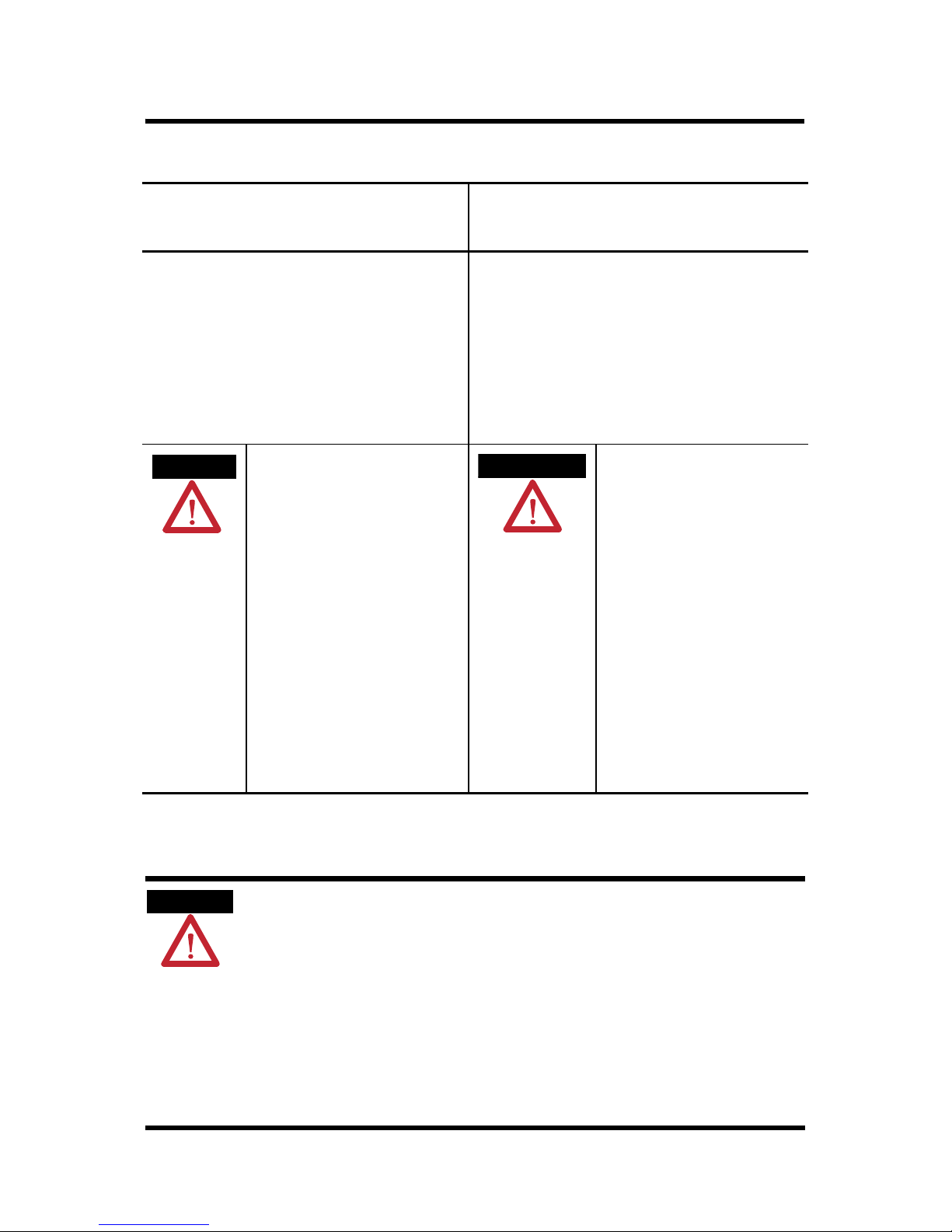
North American Hazardous Location Approval
The following information applies when
operating this equipment in hazardous
locations.
Products marked "CL I, DIV 2, GP A, B, C, D" are suitable for
use in Class I Division 2 Groups A, B, C, D, Hazardous
Locations and nonhazardous locations only. Each product is
supplied with markings on the rating nameplate indicating
the hazardous location temperature code. When
combining products within a system, the most adverse
temperature code (lowest "T" number) may be used to help
determine the overall temperature code of the system.
Combinations of equipment in your system are subject to
investigation by the local Authority Having Jurisdiction at
the time of installation.
WARNING
EXPLOSION HAZARD -
• Do not disconnect equipment unless
power has been removed or the
area is known to be nonhazardous.
• Do not disconnect connections to
this equipment unless power has
been removed or the area is known
to be nonhazardous. Secure any
external connections that mate to
this equipment by using screws,
sliding latches, threaded
connectors, or other means
provided with this product.
• Substitution of components may
impair suitability for Class I,
Division 2.
• If this product contains batteries,
they must only be changed in an
area known to be nonhazardous.
Informations sur l’utilisation de cet
équipement en environnements dangereux.
Les produits marqués "CL I, DIV 2, GP A, B, C, D" ne
conviennent qu'à une utilisation en environnements de
Classe I Division 2 Groupes A, B, C, D dangereux et non
dangereux. Chaque produit est livré avec des marquages sur
sa plaque d'identification qui indiquent le code de
température pour les environnements dangereux. Lorsque
plusieurs produits sont combinés dans un système, le code de
température le plus défavorable (code de température le plus
faible) peut être utilisé pour déterminer le code de
température global du système. Les combinaisons
d'équipements dans le système sont sujettes à inspection par
les autorités locales qualifiées au moment de l'installation.
AVERTISSEMENT
RISQUE D’EXPLOSION –
• Couper le courant ou s'assurer
que l'environnement est classé
non dangereux avant de
débrancher l'équipement.
• Couper le courant ou s'assurer
que l'environnement est classé
non dangereux avant de
débrancher les connecteurs. Fixer
tous les connecteurs externes
reliés à cet équipement à l'aide
de vis, loquets coulissants,
connecteurs filetés ou autres
moyens fournis avec ce produit.
• La substitution de composants
peut rendre cet équipement
inadapté à une utilisation en
environnement de Classe I,
Division 2.
• S'assurer que l'environnement est
classé non dangereux avant de
changer les piles.
Preventing Electrostatic Discharge
ATTENTION
This equipment is sensitive to electrostatic discharge, which can cause internal
damage and affect normal operation. Follow these guidelines when you handle
this equipment:
• Touch a grounded object to discharge potential static.
• Wear an approved grounding wriststrap.
• Do not touch connectors or pins on component boards.
• Do not touch circuit components inside the equipment.
• Use a static-safe workstation, if available.
• Store the equipment in appropriate static-safe packaging when not in use.
Publication
1768-IN004D-EN-P - December 2009
6 CompactLogix Controllers
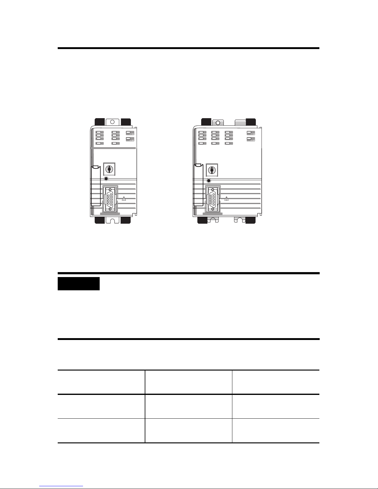
About CompactLogix Controllers
CompactLogix 1768-L43 and 1768-L45 controllers are designed to
provide a Logix solution for medium-sized applications. Compact
GuardLogix controller catalog numbers end in ‘S’. These safety
controllers are wider than their standard counterparts.
1768-L43, 1768-L45 1768-L43S, 1768-L45S
Verify Compatibility
IMPORTANT
This table shows the compatible RSLogix 5000 software versions and
controller firmware revisions.
Controllers RSLogix 5000 Software
1768-L43 and 1768-L45,
Series B
Attempting to use controllers with incompatible software and firmware
revisions may result in:
• an inability to connect to the series B controller in RSLogix 5000
software.
• unsuccessful firmware upgrades in ControlFlash or AutoFlash
utilities.
Controller Firmware
Version or Later
16.03 16.23
Revision or Later
1768-L43S and 1768-L45S,
Series B
Publication
1768-IN004D-EN-P - December 2009
18 18
CompactLogix Controllers 7
Required System Components
You need these parts when installing your controller:
• 1768-L43, 1768-L43S, 1768-L45, or 1768-L45S CompactLogix
controller
• 1768-PA3 or 1768-PB3 power supply
• 1769-ECR end cap
• Mounting screws (M4 or #8 panhead) or one of these
EN 50 022 DIN rails:
– 35 x 7.5 mm (1.38 x 0.30 in.)
– 35 x 15 mm (1.38 x 0.59 in.)
• 1756-CP3 serial cable (or make your own)
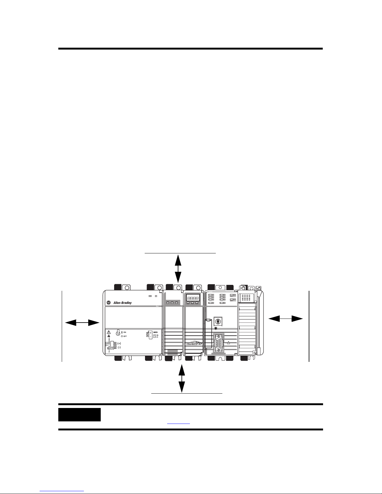
Clearance Requirements
Allow for the minimum clearance from enclosure walls, wireways,
and other equipment.
105 mm (4.13 in.)
90 mm
(3.54 in.)
IMPORTANT
Power
L1
L2/N
OUT
31609-M
105 mm (4.13 in.)
These minimum clearances keep the modules cool enough in most situations.
See Specifications on page 32
for the acceptable temperature range.
90 mm
(3.54 in.)
Publication
1768-IN004D-EN-P - December 2009
8 CompactLogix Controllers
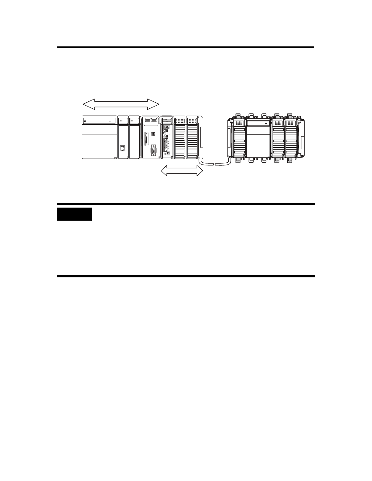
Module Placement
1768 Backplane (local)
1768 Controller, Power
Supply, and I/O Modules
Remote Bank
1769 Power Supply and
I/O Modules
1769 Backplane
IMPORTANT
CompactLogix System Distance Ratings
Because the 1768 CompactLogix power supply works with the controller to
power a 1768 system, the distance rating in a 1768 CompactLogix system differs
from that in a 1769 CompactLogix system.
In the 1768 system, the distance rating is the distance between 1769 I/O modules
and the controller. In the 1769 system, the distance rating is the distance
between 1769 I/O modules and the power supply.
Follow these requirements to determine proper placement of your
1768 controller, power supply, 1768 I/O modules, and 1769 I/O
modules:
• Place the 1768-L4xx controller so that it is the last module
(furthest away from the power supply) in the 1768 backplane.
• The 1768 CompactLogix power supply distributes power from
the right side of the supply and must be the leftmost module
in the system.
• Up to eight 1769 I/O modules can reside in the local bank.
• The local bank is powered by a 1768 power supply.
• Up to two remote banks of 1769 I/O modules may be
connected by using 1769-CRLx extension cables.
• Remote banks are powered by a standard 1769 power supply.
Publication
1768-IN004D-EN-P - December 2009
CompactLogix Controllers 9
• Up to eight 1769 Compact I/O modules can reside on each
side of a 1769 power supply in a remote bank. Consult the
module’s specifications for its distance rating.
IMPORTANT
Never place a 1769 power supply in a local bank with a 1768
controller or a major fault will occur.
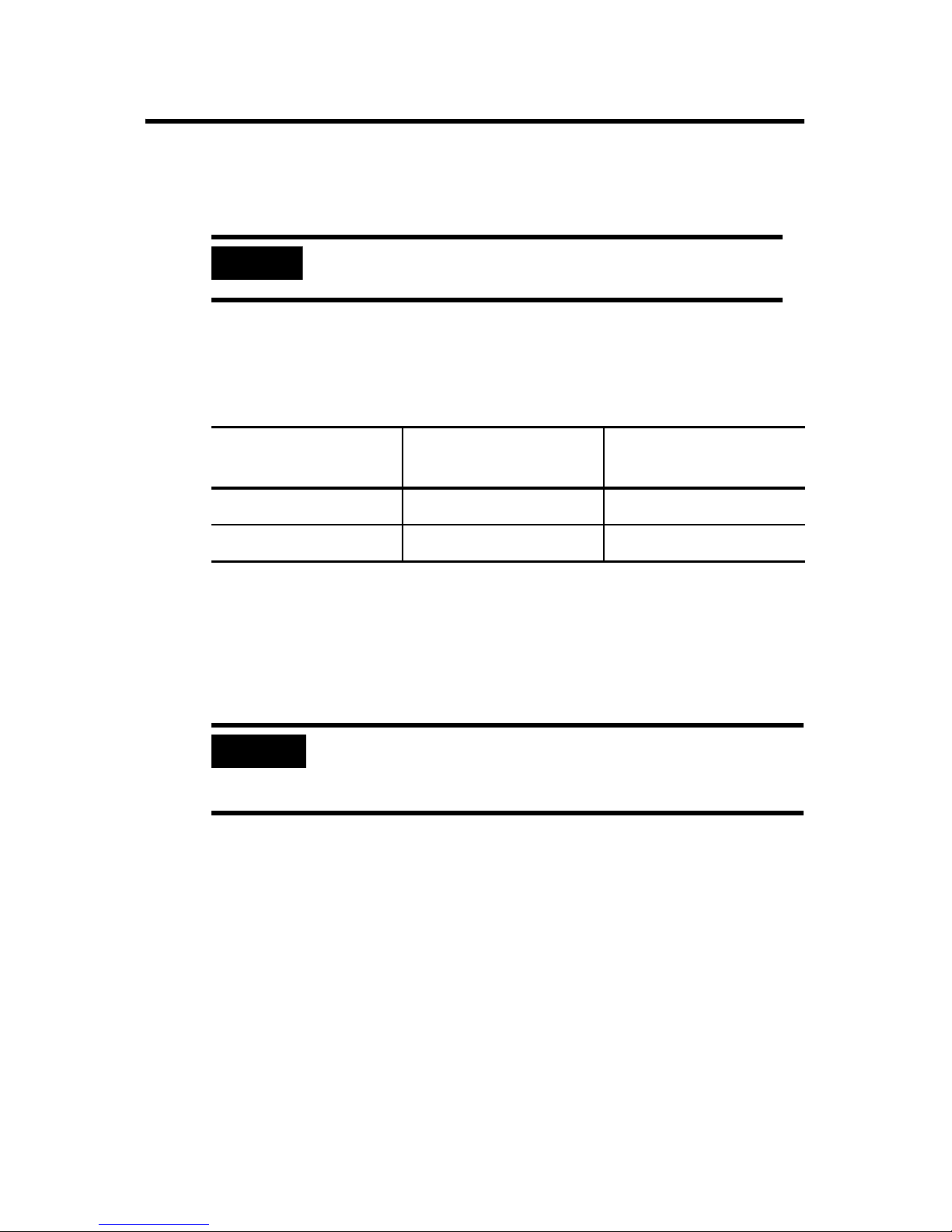
• The type of controller determines the maximum number of
1768 modules that can reside in the local bank and the
maximum number of 1769 I/O modules that can reside in one
local and up to two remote banks.
Controller Max Local 1768
Modules
1768-L43, 1768-L43S 2 16
1768-L45, 1768-L45S 4 30
Max 1769 I/O Modules
(local and remote)
Install the Controller
Follow these steps to install your controller.
1. Mount the controller to a panel or on a DIN rail.
IMPORTANT
Do not use screws if using a DIN rail to mount the controller. You can
break the mounting tabs if you screw the controller to a panel while it
is on a DIN rail.
2. Confirm the installation.
3. Connect the controller.
4. Configure a serial or Ethernet driver.
5. Install a CompactFlash card (optional).
6. Download and install controller firmware.
Publication
1768-IN004D-EN-P - December 2009
10 CompactLogix Controllers
Panel Mount the Controller
Follow these steps to mount your controller by using the panhead
screws.
1. Connect the CompactLogix modules together as shown in
Mount the Controller on a DIN Rail
on page 10.
2. Use the controller as a template and mark pilot holes on your
panel.
3. Drill the pilot holes for M4 or #8 screws.
ATTENTION
During mounting of all devices, be sure that all debris (such as metal
chips or wire strands) is kept from falling into the controller or I/O
modules. Debris that falls into the controller or modules could cause
damage while the controller is energized.
4. Use M4 or #8 screws to mount the controller to your panel
with 1.16 N•m (10 lb•in) of torque.
5. Ground the module on a ground bus with a dedicated earth
ground stake.
6. Connect the ground bus to a functional earth ground on the
panel or a DIN rail.
Mount the Controller on a DIN Rail
ATTENTION
Publication
This product is grounded through the DIN rail to chassis ground. Use zinc
plated yellow-chromate steel DIN rail to assure proper grounding. The use of
other DIN rail materials (for example, aluminum and plastic) that can corrode,
oxidize, or are poor conductors, can result in improper or intermittent
grounding. Secure DIN rail to the mounting surface approximately every
200 mm (7.87 in.) and use end anchors appropriately.
1768-IN004D-EN-P - December 2009
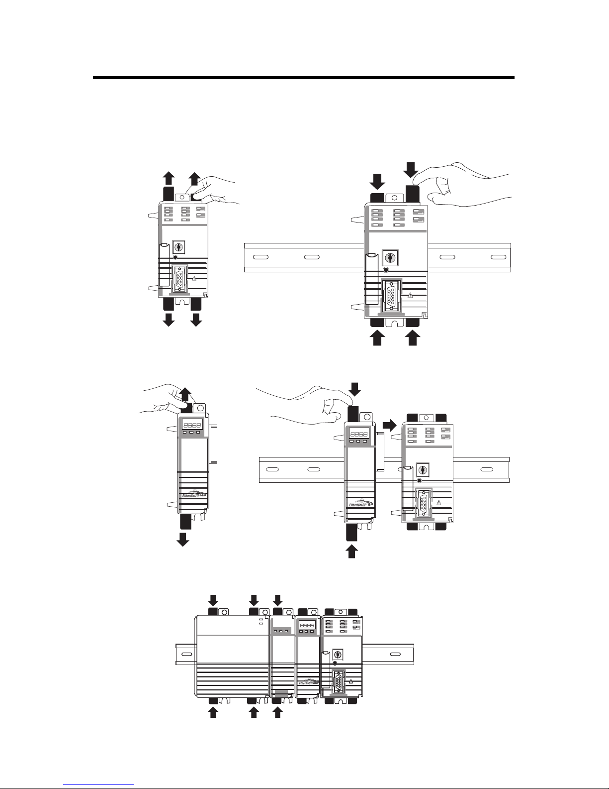
Mount 1768 Components
Follow these steps to mount the controller.
1. Mount the controller on the DIN rail.
CompactLogix Controllers 11
a.
31595-M
b.
31596 -M
2. Mount additional 1768 modules to the left of the controller.
a.
c.
b.
a.
3. Mount the 1768 power supply and other 1768 modules.
31597-M
Publication
c.
31599-M
31598 -M
1768-IN004D-EN-P - December 2009
 Loading...