


 ®
®
REMINGTON
Powerdriver™
Model 490
POWDERACTUATEDTOOL™
MANUFACTURERS´INSTITUTEINC.
Operating
Instructions
Important:
Read all instructions and warnings found in this manual and on power load packaging before operating your powder actuated tool. This manual should always accompany the tool and be transferred with it upon change of ownership.
Index |
|
Warning: Safety Precautions ........................................... |
3-11 |
Why A Fastener Holds......................................................... |
12 |
Selecting Fasteners and Power Loads ................................ |
13 |
Operation....................................................................... |
14-16 |
Parts List.............................................................................. |
17 |
Accessories......................................................................... |
17 |
Barrel Replacement....................................................... |
18, 19 |
Tool Disassembly and Assembly................................... |
19, 20 |
Troubleshooting Guide................................................... |
21, 22 |
Application Chart........................................................... |
22, 23 |
Replacement Parts and Accessories .................................. |
24 |
Technical Service ................................................................ |
24 |
Repair Service..................................................................... |
24 |
Parts Centrals...................................................................... |
25 |
Limited Warranty.................................................................. |
26 |
REMINGTON® |
|
Powerdriver™ Model 490 |
|
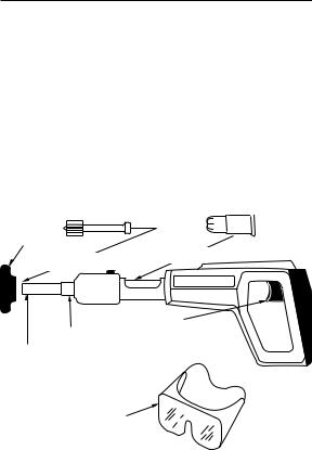
The Remington® Powerdriver™ Model 490 is designed for use withRemington® .22caliber,TypeA,neck-downcrimpedpower loads and Remington® Power Fasteners which are no longer than 2 1/2" or power washer fasteners no longer than 3". Remington® Power Fasteners are manufactured from special steel and heat treated to produce a very hard, yet ductile, fastener.
Spall
Shield*
Power Fastener* |
Power Load* |
|
|
|
REMINGTON |
Trigger
Barrel Assembly
Muzzle
Recommended
Approved Eye
Protection*
* Not provided with tool.
2101274
 Warning: Safety
Precautions
The following pages contain detailed warnings, cautions, and rules of safe operation. Read carefully and become familiar before operating to avoid serious injury.We expressly disclaim any liability for any injury to persons or damage to property which result from your failure to take the precautions contained in this manual.
 WARNING:This tool is designed only for use by qualified operators. Qualification is obtained through a thorough understanding of the Safety Precautions and operating instructions as defined in this operating manual. NOTE: The labor regulations of many states require that the operator of this tool on a job site be thoroughly trained and certified for competence prior to operating this tool. For certification procedures, call: DESA Specialty Products™ Technical Services Department,
1-800-858-8501 or visit www.desatech.com.
BEFORE USING
 ? ?
? ?
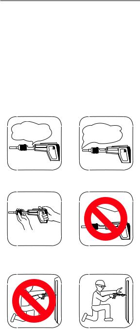
1.ALWAYS handle the tool as if it were loaded. Before starting work, check that the tool is unloaded and the muzzle is clear. NEVER load a tool unless it is going to be used.
2.ALWAYS inspect to make sure the tool is working properly. If the tool does not work properly, remove from service and tag DEFECTIVE. DO NOT use the tool again until it has been properly repaired.
3. OperatorsandbystandersmustALWAYSweargogglesand ear protection which meet or exceed ANSI standards.
101274 3
Safety Precautions
WARNING
POWDER
ACTUATED !
TOOLS
IN USE
4.ALWAYScleartheworkareaonallsidesandpostappropriate warning signs on job sites.
5.ALWAYS make sure the work area is clean from loose material and debris.
HANDLINGTHETOOL
1.NEVER place your hand over the muzzle. Accidental discharge can cause serious injury.
2. NEVER place your finger on the trigger until the muzzle of the tool is against the work surface.
4 101274

Safety Precautions
POWE |
POWER |
LOAD |
|
|
LOADS |
3.ALWAYS store UNLOADED powder actuated tool and power loads in a locked container. Keep power loads of different power levels in separate containers.
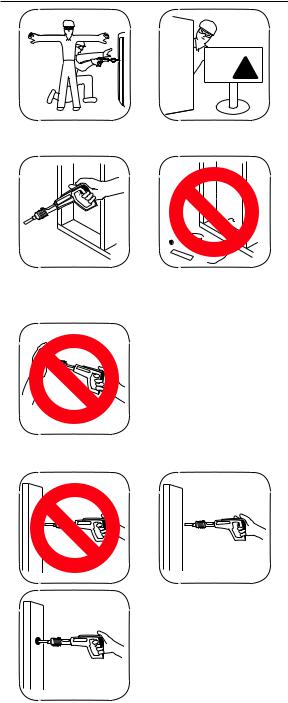
4.NEVER carry or pass a loaded powder actuated tool. NEVER point a powder actuated tool at anyone.
5.Ifthetoolisdropped,inspectfordamageandrepairitbefore continuing to work. NEVER use a damaged tool.
6.ALWAYS take precautions to maintain your balance while operating a powder actuated tool.
101274 |
5 |
Safety Precautions
7.An operator taking medication should take extra precautions while handling the tool.NEVER drink alcoholic beveragesortakemedicationswhichimpairyourvision,balance, or judgement before using a powder actuated tool.
KNOWYOUR FASTENING BASE MATERIAL

 ? ??
? ??


 ?
?
CENTER
PUNCH TEST
|
Start |
1 |
2 |
GRAY |
BROWN |
3 |
4 |
GREEN |
YELLOW |
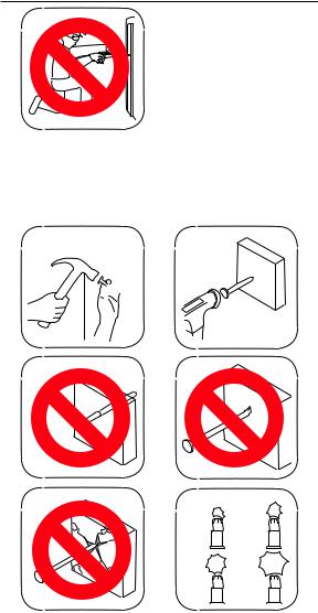
1.ALWAYS know the thickness and type of base material into whichyouare fastening.NEVERGUESS.Testthe basematerialbyusingtheCenterPunchTest.TheCenterPunchTest is performed by using a hammer to test drive the particular power fastener to be used into the material.If the point penetrates easily, the material is too soft. If the point becomes blunt,thematerialistoohard.Ifthematerialfractures,cracks or shatters, the material is too brittle.Test fastenings can be made if the material shows a clear power fastener impressionandthepowerfastenerpointisnotblunted.Alwaysstart with the lowest power load (Gray-Level 1) and proceeding with the order shown in the lower right-hand figure above. ALWAYS wear approved eye protection.
6101274
Safety Precautions
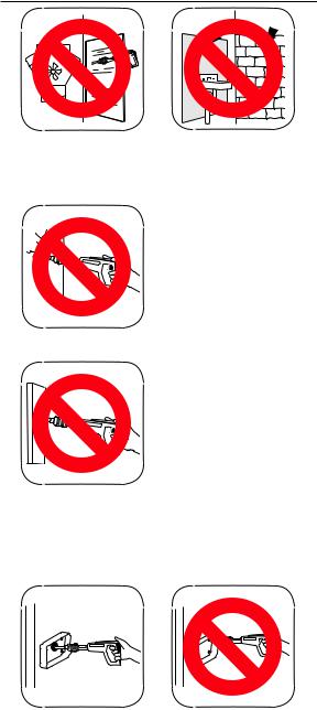
2.NEVER attempt to drive power fasteners into very hard or brittle materials including, but not limited to cast iron, glass, tile, stone, brick, or hardened steel. Materials of this type tend to shatter and create hazard from flying particles.
3. NEVER make fastenings in spalled or cracked areas.
4.NEVER drive power fasteners into thin or easily penetrated material unless it is backed by concrete or steel. When in doubt, such as when base material is concealed, conduct a Center Punch Test (See page 6). Check continually to avoid fastening into unsuitable material, especially in older buildings.
5.DO NOT fasten through or within 1/2" of predrilled or prepunched holes.
101274 |
7 |

Safety Precautions
 3"
3"
3" 
3"
 3"
3"
1X
3X
6.DONOTdrivepowerfastenersintoconcretelessthanthree times as thick as the intended power fastener penetration, within 3" of the edge, within 3" of another power fastener, or within 3" of a failed power fastener.
1"
 1/2"
1/2"
 3/16" MIN
7.DO NOT drive power fasteners into steel base material less then 3/16" thick, within 2" of a weld, within 1/2" of the edge, or within 1" of another power fastener.
YES
8.When fastening into masonry walls, always drive into horizontal mortar joints, NEVER into vertical mortar joints. BE CAREFUL, a poorly laid joint may permit too much penetration and/or unsatisfactory holding power.
OPERATINGTHETOOL


 90˚
90˚
1. ALWAYS hold tool perpendicular to work surface.
8101274

Safety Precautions
30
WATER
2.Should the tool fail to fire, hold the muzzle firmly against the work surface for 30 seconds. Release the trigger and remove pressure on the tool while holding the muzzle againsttheworksurface.Againpressthetoolfirmlyagainst the work surface and pull the trigger. If the tool still fails to fire, hold the tool firmly against the work surface for another 30 seconds before unloading and carefully discarding the misfired power load into water or oil.
Spall
Shield
3.ALWAYS use the spall shield when driving directly into concrete or steel. ALWAYS wear eye protection.
4.NEVER use a powder actuated tool in an explosive or flammable atmosphere or when non-sparking tools are required.
POWER LOADS AND POWER FASTENERS
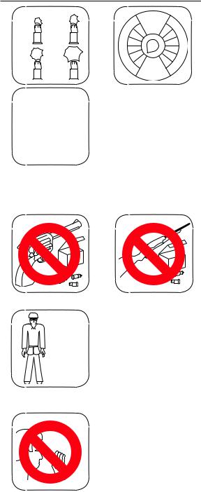
1. NEVER leave unfired power loads on floors or work surfaces.
101274 |
9 |
Safety Precautions
Start
12
GRAY BROWN
S
S
A
R
B
34
GREEN YELLOW
|
22 |
|
|
B |
|
ALI E |
R |
|
C |
|
|
67
58
4 |
1 |
9 |
|
3 |
10 |
||
|
211
1 12
N
I
C K E L
NOTE:
Failure to start with the lowest power level can result in overdrive condition and will result in damage to tool (see page 13).
2.Remington® PowerLoadsareavailableinfourpowerlevelswith gray (1) being the lowest power level and yellow (4) being the highest power level. Always start with the lowest power level (gray-level1)andincreaseuntilaproperfasteningismade(see page 13, Selecting Power Fasteners and Power Loads).
3. NEVER use power loads in firearms.
POWER
LOADS
 ONLY
ONLY
4.NEVER carry power fasteners or other hard objects in the same pocket or container with power loads.
5.A color blind person must take extra precautions to prevent the chance of mixing the power loads of various levels.
10 |
101274 |
Safety Precautions
6.Power fasteners are a permanently installed fixture. An act of demolition is required for their removal. Appropriate safety precautions must be taken.
Head
Shank
Plastic Flute
7.NEVER use common nails or other materials as fasteners. Remington® Power Fasteners are manufactured from special steel and heat treated to produce a very hard, yet ductile, fastener.
8.NEVER pry a power load out of the chamber. Prying can discharge the load causing serious injury (see Troubleshooting Guide on pages 21 and 22).
|
LOAD |
|
UNLOAD |
1 |
2 |
2 |
1 |
|
REMINGTON |
|
REMINGTON |
9.ALWAYS insert the power fastener first, then the power load.If work is interrupted for any reason, ALWAYSremove the power load before removing the power fastener (see page 15, item 7).
101274 |
11 |
Why a Power
Fastener Holds
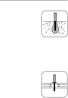
WHY A POWER FASTENER HOLDS IN CONCRETE
The compression bond of the concrete to the power fastener accounts for the majority of the holding power.
Thepowerfastenerdisplacestheconcretewhichtriestoreturntoitsoriginal form causing a squeezing effect.
Maximum holding power is achieved when the depth of penetration produces a bond on the power fastener equal to the strength of the concrete.
As a general rule, penetration should be approximately 1" to 1 1/4" into the base concrete. Make sure the concrete is at least three timesasthickastheintendedpowerfastenerpenetration.NEVER have the power fastener point protrude thru the concrete.
NOTE:Concreteneedstocurefor28daysbeforemaximum fastening holding power will be achieved.
WHY A POWER FASTENER HOLDS IN STEEL
Holding power in steel depends on the elasticity of the steel. The steel pushes back on the shank of the power fastener.
Drop a marble into water; the water parts, the marble continues down, thewaterclosesback.Thisissimilar
to the reaction when a power fastener penetrates steel.
In steel, the point of the power fastener must penetrate completely through for highest holding power.If the power fastener does not penetrate, the spring action of the steel pushes back on the point and tends to force the power fastener out.
Recommended applications are between 3/16-3/8" steel.
NOTE: When fastening in steel be sure the point goes thru the steel.
12 |
101274 |

Selecting Power
Fasteners and
Power Loads
FASTENING INTO CONCRETE
The proper power fastener length can be determined by adding the thickness of the material to be fastened and the amount of power fastener that will actually penetrate the concrete.The concrete must be three times as thick as the intended power fastener penetration.In most cases, penetration should be approximately 1" to 1 1/4" into the base concrete material.
Wood or Non-Metals To Concrete
FASTENING INTO STEEL
Theproperpowerfastenerlengthcan be determined by adding the thickness of the material to be fastened and the thickness of the steel. The point of the power fastener must go completely through the steel.
POWER LOADS
Always start with the lowest power level (gray-level 1). If the first test power fastener does not penetrate to the desired depth, move to the next highest power level (brown-level 2).
Increase until a proper fastening is made.IMPORTANT:Damagetothe tool will result if the above instructions are not followed (see illustrations to right and lower right).
Wood or Non-Metals To Steel
RIGHT
Flush With Surface
OVERDRIVEN POWER |
|
|
FASTENERS AND PISTON |
OVERDRIVE |
|
An overdriven power fastener re- |
||
|
||
sults when too strong of a power |
|
|
load is used causing the piston to |
|
|
extend past the muzzle. Move to the |
|
|
next lightest power load. Repeated |
|
|
overdrive will damage your tool. By |
|
|
avoiding overdrive, you can extend |
|
|
the life of your tool considerably. |
|
NOTE: NEVER fire the tool without a power fastener.This can damage thetooland/orcausepossibleinjury to the operator.
Piston Extended
Out of Muzzle
IMPORTANT: DO NOT use power fasteners longer than 2 1/2", or power washer fasteners longer than 3". Power fasteners longer than 2 1/2" and power washer fasteners longer than 3" will cause load ejection problems.
101274 |
13 |

Operation
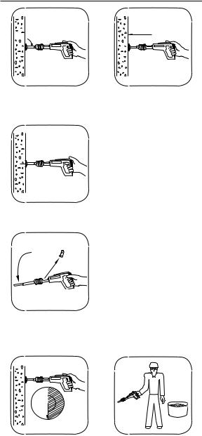
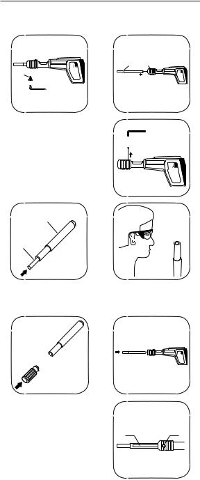
1.Grasp muzzle and slide barrel forward rapidly until it stops. This sets piston into firing position and opens the chamber.
2.Insert power fastener into muzzle of tool, head end first.Push thepowerfasteneruntilpointisevenwithendoftool.ALWAYS load the power fastener first, then the power load.
NOTE:
Failure to start with thelowestpowerlevel canresultinoverdrive condition and will result in damage to tool (see page 13).
3.SelecttheproperRemington® PowerLoad(seeApplication Chartonpages22and23)andinsertintothechamberuntil it stops.
4. Push barrel into housing to the closed position.
14 101274
Operation


 90˚
90˚
5.Place the muzzle of tool perpendicular to work surface without tilting the tool. Push tool against work surface until sliding action of barrel stops.
6.Squeeze trigger to set power fastener. Be sure to keep pressure on tool during this operation.
7.After fastening is made, slide barrel forward rapidly. This motion ejects the spent power load and resets the piston for the next fastening. Make sure spent load has ejected from tool.
30
WATER
8.Should the tool fail to fire, hold the muzzle firmly against the work surface for 30 seconds. Release the trigger and remove pressure on the tool while holding the muzzle againsttheworksurface.Againpressthetoolfirmlyagainst the work surface and pull the trigger. If the tool still fails to fire, hold the tool firmly against the work surface for another 30 seconds before unloading and carefully discarding the misfired power load into water or oil.
101274 |
15 |
Operation
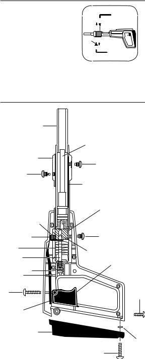
PISTON OVERDRIVE
If the tool does not open after firing and the piston is 1/2 inch or more out of the muzzle:
1.Strike muzzle end of Powerdriver™ against hard surface to force piston back into muzzle.
2.Eject the power load (See step 7 of Operation).
OVERDRIVE
CARE OFYOUR POWERDRIVER™
Clean your Powerdriver™ after each day’s use.Clean chamber with accessory wire brush, part number 56485 (Not included with tool).Apply good quality penetrating lubricant spray (such as WD-40) sparingly and wipe dry.
NOTE: The labor regulations of many states require that the operator of this tool on a job site be thoroughly trained and certified for compentence prior to operating this tool. For certification procedures, call: Technical Services Department, 1-800-858-8501 or visit www.desatech.com.
16 |
101274 |
|
|
|
|
|
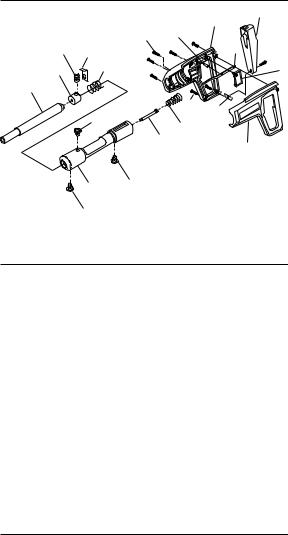
Parts List |
||
|
|
|
|
|
|
3 |
7 |
|
|
|
|
|
9 |
|
|
|
|
|
|
14 |
|
|
|
|
18 |
15 |
|
|
|
5 |
|
|
2 |
|
16 |
|
|
|
19 |
|
|
|
|
|
|
||
|
1 |
|
|
|
|
|
|
|
|
|
|
|
13 |
6 |
|
|
|
|
|
|
|
|
|
|
|
20 |
|
17 |
|
|
|
|
|
|
|
8 |
|
|
|
|
|
|
|
|
|
4 |
|
|
|
|
|
|
|
|
|
|
|
10 |
12 |
|
|
|
|
|
|
|
|
|
|
||
|
|
11 |
|
|
|
|
|
Key |
|
|
|
|
|
|
|
No. |
Part No. |
|
Description |
|
|
Qty. |
|
1 |
TA4080 |
|
BARREL, Assembly and Piston |
1 |
|||
2 |
076659 |
|
BREECH |
|
|
1 |
|
3 |
076620 |
|
HOUSING, Handle, Right |
1 |
|||
4 |
076630 |
|
HOUSING, Handle, Left |
|
1 |
||
5 |
078334 |
|
LINK, Trigger |
|
|
1 |
|
6 |
076943 |
|
NUT, Pad Recoil |
|
1 |
||
7 |
098679-01 |
PAD, Recoil |
|
|
1 |
||
8 |
075370 |
|
PIN, Firing |
|
|
1 |
|
9 |
044279 |
|
PIN, Spring |
|
|
1 |
|
10 |
098720-01 |
RECEIVER, Assembly |
|
1 |
|||
11 |
055436 |
|
SCREW, Barrel |
|
1 |
||
12 |
077183 |
|
SCREW, Breech |
|
1 |
||
13 |
076674 |
|
SCREW, Housing |
|
2 |
||
14 |
077277 |
|
SCREW, Housing |
|
6 |
||
15 |
076657 |
|
SEAR |
|
|
1 |
|
16 |
077191 |
|
SPRING, Breech |
|
1 |
||
17 |
056217 |
|
SPRING, Pin, Firing |
|
1 |
||
18 |
056218 |
|
SPRING, Sear |
|
|
1 |
|
19 |
076671 |
|
TRIGGER |
|
|
1 |
|
20 |
077708 |
|
PAD, Pressure Assembly |
1 |
|||
ACCESSORIES |
|
|
|
|
|||
|
Part No. |
|
Description |
|
|
||
|
TA4090 |
|
SHIELD, Spall |
|
|
||
|
056415 |
|
GOGGLES |
|
|
||
|
056485 |
|
BRUSH, 1/4" |
|
|
||
|
056486 |
|
BRUSH, 5/8" |
|
|
||
|
103754 |
|
HEX WRENCH, 3/16" |
|
|||
IMPORTANT: Do not use key numbers when ordering service parts. Always order components by part number and description. Include Model and Serial numbers.
101274 |
17 |
Barrel Replacement
 WARNING: Never disassemble, replace barrel, clean, or assemble a powder actuated tool while it is loaded.
REMINGTON
A 

1.Remove front screw (A). Slide barrel assembly (B) from receiver (C). Remove pressure pad assembly (D).
BC
REMINGTON

 D
D
REMINGTON
B
E
2.If tool has been overdriven, tap piston (E) on a hard surface until the piston is pushed back into the muzzle. Inspect the barrel assembly (B) and replace if damaged.
REMINGTON
3. To assembly, push piston |
|
|
all the way into the barrel. |
|
|
Slide the barrel assembly |
F |
A |
intothereceiver.Turnbarrel |
||
to line up slot (F) with front |
|
|
screw hole (A). |
|
|
18 |
101274 |
Barrel Replacement
4.Insert screw (A) and tighten. Insert and tighten pressure pad assembly (D).

 D
D
REMINGTON
A 
Tool Disassembly
And Assembly
B |
|
|
E |
C |
A |
D |
|
|
F |
|
V |
Q |
|
P |
S |
U |
T |
K |
R |
O L |
|
J |
|
|
I |
N |
|
H |
|
|
M |
|
G |
101274 |
19 |

Tool Disassembly
And Assembly
TOOL DISASSEMBLY
1.Remove screw (G) from recoil pad (H). Lift pad away from handle. Separate housing halves by removing the seven housing screws (I & J).
2.Remove receiver (C), firing pin (K), firing pin spring (L), sheet metal nut (M), trigger link (N), link pin (O), sear (P), and trigger (R).
3.Push barrel assembly (B) into receiver (C). Remove screw
(S) from receiver. Remove front screw (A), pressure pad assembly (D), barrel assembly (B), breech (T), and breech spring (U).
4.Clean your tool after each days use by using a penetrating lubricant such as “WD-40”sparingly and wipe dry.Brushes are available through your distributor to aid in cleaning.
TOOL ASSEMBLY
1.Push the piston (E) all the way into the barrel (B). Insert breech spring (U), the breech (T) and barrel assembly (B) into the receiver (C). Make sure the breech slot (V) in the breech (T) is aligned with the hole for breech screw (S).
2.Push the barrel assembly (B) forward until the breech slot
(V)is visible through the hole for breech screw (S). Insert and tighten breech screw (S).Align barrel slot (F) with hole for front screw (A).Insert and tighten front screw (A).Insert and tighten pressure pad assembly (D).
3.Insert link pin (O) into housing half. Assemble sear spring
(Q)in pocket of breech (T).Insert sear (P) into breech with solid leg facing forward and keyhole leg down. Assemble small end of firing pin spring (L) onto end of firing pin (K) and insert into rear of receiver (C).
4.Placebreechendofreceiverintohousing.Assembletrigger link (N) on link pin (O) with angled end of trigger link up over sear (P).
5.Assemble trigger (R) into housing half. Insert sheet metal nut (M) into housing pocket with hollow side towards grip. Assemble housing halves.
6.Insert short screws (I) into handle bottom.Longer screws (J) into remaining holes in side of housing.Tighten uniformly.
7.Assemble upper part of recoil pad (H) into housing. Insert screw (G) into lower part of recoil pad (H) and tighten.
8.Test tool without power load by depressing barrel against worksurface,pullingtrigger,andreleasingtool.Testseveral times to insure that the firing mechanism operates freely.
20 |
101274 |
Troubleshooting Guide
|
|
POSSIBLE |
|
|
|
|
PROBLEM |
|
CAUSE |
REMEDY |
|
|
|
Piston hangs |
|
Tool overdriven. |
Tap piston on a hard |
|||
out of muzzle. |
|
|
surface |
until |
piston is |
|
|
|
|
pushed |
back |
into the |
|
|
|
|
muzzle (see Overdriven |
|||
|
|
|
Fastener, below). |
|||
|
|
|
|
|
||
|
|
Piston not properly |
Remove |
barrel assem- |
||
|
|
assembled in rela- |
bly. Follow |
instructions |
||
|
|
tion to barrel screw. |
for barrel |
replacement |
||
|
|
|
(see pages 18 and 19). |
|||
|
|
|
Replace all damaged or |
|||
|
|
|
missing parts. |
|
||
|
|
|
|
|||
|
|
Broken piston. |
Replace barrel assem- |
|||
|
|
|
bly or take tool to your |
|||
|
|
|
distributor. |
|
|
|
|
|
|
|
|
||
Overdriven fas- |
|
Excessive power. |
Change |
either to next |
||
tener. |
|
|
lowerpowderloadornext |
|||
|
|
|
longer length fastener. |
|||
|
|
|
|
|
||
Piston jammed. |
|
Overdriving of fas- |
Remove |
barrel assem- |
||
|
|
tener (see above). |
bly. Follow |
instructions |
||
|
|
|
for barrel |
replacement |
||
|
|
|
(see pages 18 and 19). |
|||
|
|
|
Replace |
other parts if |
||
|
|
|
damaged. |
|
|
|
|
|
|
|
|||
Expended load |
|
Dirty or damaged |
Clean chamber. If loads |
|||
will not extract. |
|
chamber. |
will not |
chamber with |
||
|
|
|
slip-fit or extraction dif- |
|||
|
|
|
ficulties |
continue, take |
||
|
|
|
tool to your distributor. |
|||
|
|
|
|
|
||
|
|
Broken ejector. |
Replace |
barrel assem- |
||
|
|
|
bly or take tool to your |
|||
|
|
|
distributor. |
|
|
|
|
|
|
|
|||
|
|
Pinsbeingusedare |
Use proper pin size. |
|||
|
|
over 2 1/2" long. |
|
|
|
|
|
|
|
|
|||
Reduction or |
|
Pistonnotreturning |
Barrel must be snapped |
|||
loss of power |
|
to full rear position. |
to the full extended posi- |
|||
|
|
|
tion to properly position |
|||
|
|
|
piston against breech. |
|||
|
|
|
|
|||
|
|
Worn piston ring or |
Replace barrel assem- |
|||
|
|
broken piston. |
bly or take tool to your |
|||
|
|
|
distributor. |
|
|
|
|
|
|
|
|||
Tool does not |
|
Misassembled or |
Remove breech and |
|||
completely de- |
|
damaged breech |
checkallpartsforcorrect |
|||
press. |
|
and firing pin parts. |
fit assembly. |
|
||
101274 |
|
21 |
|
|
|
|
|
|
|
|
|
||

Troubleshooting Guide
PROBLEM |
POSSIBLE |
|
REMEDY |
||||
CAUSE |
|
|
|||||
|
|
|
|
|
|||
Tool |
does |
not |
Failure of tool to |
See data listed under |
|||
fire. |
|
|
|
depress |
com- |
Tool does not completely |
|
|
|
|
|
pletely. |
|
|
depress, above. |
|
|
|
|
|
|||
Tool |
does |
not |
Dirt build-up on |
Check firing pin indenta- |
|||
fire. |
|
|
|
breech not |
allow- |
tion on cartridge. Clean |
|
|
|
|
|
ing proper |
pen- |
breech,breechface,sear |
|
|
|
|
|
etration |
of |
firing |
and firing pin. Replace |
|
|
|
|
pin. |
|
|
worn or damaged parts. |
|
|
|
|
|
|||
Opening |
and |
Lack of |
proper |
Inspect and clean com- |
|||
closing of bar- |
cleaning. |
|
|
plete tool. Replace worn |
|||
rel or |
pushing |
|
|
|
or damaged parts. |
||
down |
on |
the |
|
|
|
|
|
tool, etc. is not |
|
|
|
|
|||
smooth but is |
|
|
|
|
|||
rough or binds. |
|
|
|
|
|||
|
|
|
|
|
|
|
|
Application Chart
Power load and power fastener application information.
For fastening |
|
Power fastener |
Power load |
this: |
to this: |
length |
color |
|
|
|
|
|
|
|
|
|
|
|
|
|
|
|
|
|
|
|
|
|
|
|
|
|
|
|
|
22 |
101274 |
Application Chart
Power load listings are recommendations only. If you are in doubt, try a test fastening using the next lightest power load.
Power fasteners and power loads are available in blister packs of 25 and cartons of 100.
IMPORTANT
•Recommended for use with Remington® power loads and power fasteners.
•Do not use power fasteners longer than 2 1/2" or power washer fasteners longer than 3".
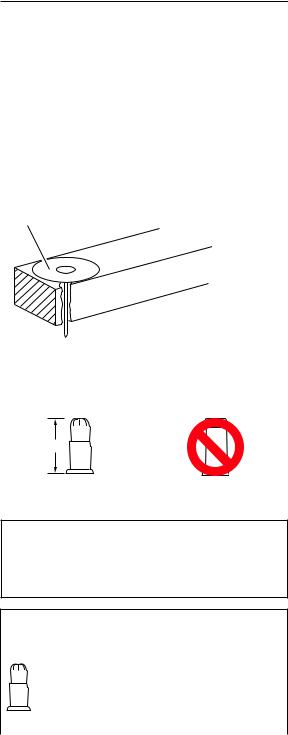
•Ifpowerfastenergoesbelowthetopsurfaceoftheboard,use penetrating control disc (see illustration below) or washered SPW-type power fasteners.
•Always wear approved eye and ear protection.
* Use power fastener with penetration control disc, part number 015549.
IMPORTANT
This tool is designed to use .22 caliber neck-down crimped loads, power levels 1 (gray) through 4 (yellow).
5/8"
Neck-Down Crimped |
Straight Wadded |
Power Load |
Power Load |
 CAUTION: Do not use any load other than the .22 caliber neck-down crimped load. Other types of loads will cause load-ejection problems.
.22 CALIBER Type A, neck-down crimp loads for powder actuated tools
|
|
Load |
|
Color Code |
|
|
Stock |
Level |
Load |
Case |
|
|
Number |
Number |
Strength |
Body |
Head |
|
|
|
|
|
|
|
A22C1 |
1 |
light |
brass |
Gray |
|
A22C2 |
2 |
medium |
brass |
Brown |
|
A22C3 |
3 |
heavy |
brass |
Green |
|
A22C4 |
4 |
extra heavy |
brass |
Yellow |
|
|
|
|
|
|
101274 |
|
|
23 |
|
|

Replacement Parts
And Accessories
WARNING: Use only replacement parts and accessoriesdescribedinthismanual.Useofotherpartsor accessories could damage tool or injure operator.
For original replacement parts and accessories, contact your nearestAuthorizedDealerorAuthorizedServiceCenterforthis product. If they can not supply the part or accessory, contact your nearest Parts Central listed on page 25. Each Authorized Dealer, Authorized Service Center, and Parts Central is independently owned and operated.
See page 17 for an Illustrated Parts List.
Ifyouneedadditionalreferralinformation,contactourTechnical Service Department (see Technical Service).
In Canada call 1-800-561-3372 for parts information.
Technical Service
You may have further questions about assembling, operating, or maintaining this product. If so, you can visit our Technical
Service web site at www.desatech.com or contact our Technical Service Department at 1-800-858-8501 (English Only).
You may also write to:
DESA Specialty Products™ P.O. Box 90004
Bowling Green, KY 42102-9004
ATTN: Technical Service Specialty Products
When contacting DESA Specialty Products™, have ready
•Your Name
•Your Address
•Your Phone Number
•Model Number of Product
•Date of Purchase (Include copy of receipt for written requests).
Repair Service
Note:Onlyuseoriginalreplacementparts.Thiswillprotectyour warranty coverage for parts replaced under warranty.
Each Authorized Service Center is independently owned and operated.
WARRANTY SERVICE
If product requires warranty service, return it to nearest Authorized
ServiceCenter.Youmustshowproofofpurchase.Iffaultymaterials or workmanship caused damage, we will repair or replace product without charge. Note: Normal wear, misuse, abuse, neglect, or accidental damage is not covered under warranty.
NON-WARRANTY SERVICE
If product requires service, return it to nearest Authorized Service Center. Repairs will be billed to you at regular repair list prices.
For additional Service Center or warranty information, call
1-800-858-8501 or visit our Technical Service web site at www.desatech.com.
24 |
101274 |
 Loading...