


O,f}PIONEER'
CIRCUIT DESCRIPTIONS |
- |
-- |
|
|
------ - |
-- |
|
REPAIR & ADJUSTMENTS |
|
|
ORDER NO. |
|
|
|
ARP-685-0 |
STEREO TURNTABLE
PL-L50
MODEL PL-L50 COM ES IN SEVEN VERSIONSDIST INGU ISHEDAS FOLLOWS:
|
Type |
Voltage |
Remarks |
|
|
|
|
|
|
|
KU |
AC120V only |
U.S.A. model |
|
|
|
|
|
|
|
KUT |
AC120V only |
U.S.A. model without cartridge |
|
|
|
|
|
|
|
KCT |
AC120V only |
Canada model without cartridge |
|
|
|
|
|
|
|
HEM |
AC220V, 240V (switchable) |
|
European continent model |
|
|
|
|
|
|
HB |
AC220V, 240V (switchable) |
United Kingdom model |
|
|
|
|
|
|
|
s |
AC110V, 120V, 220V, 240V (switchable) |
General export model |
|
|
|
|
|
|
|
SIG |
AC110V, 120V, 220V, 240V (switchable) |
U.S. Military model |
|
|
|
|
|
|
• |
This service manual is applicable to the KU, KUT, KCT, HB, HEM, Sand S/G types. |
|||
• |
As to the KUT, KCT, HEM, HB, Sand S/G types please refer to pages 47 - 48. |
|||
•Ce manual d'instruction se refere au mode de reglage, en fran ais.
•Este manual de servicio trata del metodo de ajuste escrito en espanol.
CONTENTS
1. |
SAFETY INFORMATION ................. |
2 |
10. |
P.C. BOARDS CONNECTION DIAGRAM ..... 26 |
|
2. |
SPECIFICATIONS ...................... |
3 |
11. |
SCHEMATIC DIAGRAM................. |
29 |
3. |
FRONT PANEL FACILITIES............... |
4 |
12. |
ELECTRICAL PARTS LIST............... |
32 |
4. |
BLOCK DIAGRAM ..................... |
5 |
1 ADJUSTMENTS ...................... |
34 |
|
5. |
CIRCUIT DESCRIPTIONS................. |
7 |
|
R GLAGE .......................... |
36 |
6. |
DISASSEMBLY ....................... |
17 |
|
AJUSTE ............................ |
38 |
7. |
PARTS LOCATIONS ................... |
20 |
14. |
TROUBLESHOOTING .................. |
40 |
8. |
EXPLODED VIEW AND PARTS LIST........ |
22 |
15. SUPPLEMENT FOR KUT, KCT, HEM, HB, |
|
|
9. |
PACKING........................... |
25 |
|
S AND S/G TYPES..................... |
47 |
PIONEER ELECTRONIC CORPORATION 4-1, Meguro 1-chome, Meguro-ku, Tokyo 153, ...Japan
PIONEER ELECTRONICS (USA] INC. P.O. Box 1760, Long Beach, California 90801 U.S.A. TEL: (BOOJ 421-1404, [BOOJ 237-0424
PIONEER ELECTRONIC (EUROPE] N.V. Keetberglaan 1. 2740 Beveren, Belgium TEL: 03/775·28·08 PIONEER ELECTRONICS AUSTRALIA PTV. LTD. 178-184 Boundary Road, Braeside, Victoria 3195, Australia
TEL: (03) 580-9911 |
FZ © NOV. 1984 Printed in Japan |
|

PL-LSO
1.SAFETY INFORMATION
1.SAFETY PRECAUTIONS
The following check should be performed for the continued protection of the customer and service tech
nician.
LEAKAGE CURRENT CHECK
Measure leakage current to a known earth ground (water pipe, conduit, etc.) by connecting a leakage current tester such as Simpson Model 22 -2 or equivalent between the earth ground and all exposed metal parts of the appli ance (input/output terminals, screwheads, metal overlays, control shaft, etc.). Plug the AC line cord of the appliance directly into a 120V AC 60Hz outlet and turn the AC power switch on. Any current measured must not exceed 0.5mA.
|
|
|
|
|
|
|
|
|
|
Reading should |
|
|
|
|
|
|
|
|
|
Leakage |
not be above |
||
Device |
|
|
|
current |
0.5mA |
||||||
under |
|
|
|
|
|
|
tester |
|
|
||
|
|
|
|
|
|
|
|||||
test |
|
|
|
|
|
|
|
||||
|
|
|
|
|
|
|
|
|
|||
|
|
|
|
|
|
|
|
|
|
|
|
|
|
|
|
Test all |
|
|
|
|
|||
|
|
|
|
exposed metal |
|
|
|
|
|||
|
|
|
|
surfaces |
|
|
|
|
|||
G) |
2-wire cord |
|
|
|
|
||||||
|
Also test with |
|
|
|
|
|
|
||||
plug reversed |
|
|
|
Earth |
|||||||
|
(Using AC adapter |
|
|
|
ground |
||||||
plug as required) |
|
|
|
|
|||||||
AC Leakage Test
ANY MEASUREMENTS NOT WITHIN THE LIMITS OUTLINED ABOVE ARE INDICATIVE OF A PO TENTIAL SHOCK HAZARD AND MUST BE COR RECTED BEFORE RETURNING THE APPLIANCE TO THE CUSTOMER.
2. PRODUCT SAFETY NOTICE
Many electrical and mechanical parts in the appliance have special safety related characteristics. These are often not evident from visual inspection nor the protection afforded by them necessarily can be obtained by using replacement components rated for voltage, wattage, etc. Replacement parts which have these special safety charac teristics are identified in this Service Manual.
Electrical components having such features are identified by marking with a 6 on the schematics and on the parts list in this Service Manual.
The use of a substitute replacement component which dose not have the same safety characteristics as the PIONEER recommended replacement one, shown in the parts list in this Service Manual, may create shock, fire, or other hazards.
Product Safety is continuously under review and new instructions are issued from time to time. For the latest information, always consult the current PIONEER Service Manual. A subscription to, or additional copies of, PIONEER Service Manual may be obtained at a nominal charge from PIONEER.
2

2. SPECIFICATIONS
Motor and Turntable
Drive System .............................................. |
Direct-drive |
|
Motor .................................................. |
DC servo motor |
|
Turntable Platter ..... |
304 mm diam. aluminum alloy die-cast |
|
Speeds ............................................. |
33-1/3 and 45 rpm |
|
Wow and Flutter .................... |
Less than *0.014% |
(WRMS) |
|
0.025% |
(WRMS) |
± 0.035% WTD Peak (DIN) Values marked with an "*" designate the wow and flutter for motor,and do not include the cartridge or tonearm load.
Signal-to-Noise-Ratio |
.................. More than 78 dB (DIN-Bl |
|
(with Pioneer cartridge model PC-300T) |
Tonearm
Type ................................... Integrated straight tomearm
PC-300T Specifications
Type .............................................................. |
IM type |
Stylus ............................. |
0.3 x0.7 mil diamond (PN-300T) |
Output Voltage ................................................. |
2.5 mV |
|
(1 kHz,5 cm/s LAT. Peak) |
Tracking Force .................... |
1.0 g to 1.5 g (proper 1.25 g) |
Frequency Response ................................ |
10 to 33,000 Hz |
Recommended Load ............................................ |
50 kQ |
Weight .............................................................. |
5.9g |
Miscellaneous |
|
|
Power Requirements |
|
|
HEM,HB,HP models |
..................... |
AC 220 V/240 V- |
|
|
(switchable),50,60 Hz |
KUT,KCT,KU,KC models ................. |
AC 120 V,60 Hz |
|
S,SIG models ........... |
AC 110 V/120 V/220 V/240 V- |
|
|
|
(switchable),50,60 Hz |
Power Consumption |
|
|
HEM,HB,HP models ........................................ |
|
13W |
KUT, KCT, KU,KC models ............................... |
12 W |
|
S,S/Gmodels ................................................ |
|
9W |
Dimensions ....................... |
420 (W) x108 (H) x365 (D) mm |
|
16-1/2 (W) x4-1/4 (H) x14-3/8 (D) in. |
||
Weight .................................................... |
|
4.8 kg/11 lb |
Accessories |
|
|
EP Adapter .............................................................. |
|
1 |
Operating Instructions ................................................ |
|
1 |
NOTE:
Specifications and design subject to possible modification without notice, due to improvements.
Subfunctions
Auto lead-in,auto return,auto cut,repeat
Arm elevation,manual play,
Auto disc size selector,record detection,
Auto speed selector
INFORMATION TO USER [FOR U.S.A. MODEL]
This equipment generates and uses radio frequency energy and if not installed and used properly, that is, in strict accordance with the manufacture's instructions, may cause interference to radio and television recep tion. It has been type tested and found to comply with the limits for a Class B computing device in accordance with the specifications in Subpart J of Part 15 of FCC
Rules, which are designed to provide reasonable protec tion against such interference in a residential installa tion. However, there is no guarantee that interference will not occur in a particular installation.
If this equipment does cause interference to radio or television reception, which can be determined by turn ing the equipment off and on, the user is encouraged to try to correct the interference by one or more of the following measures:
reorient the receiving antenna
relocate this component with respect to the receiver
move this component away from the receiver plug this component into.a different outlet so that component and receiver are on different branch cir cuits.
If necessary, the user should consult the dealer or an ex perienced radio/television technician for additional sug gestions. The user may find the following booklet prepared by the Federal Communications Comission helpful:
"How to Identify and Resolve Ratio-TV Interference Problems".
This booklet is available from the US Government Prin ting Office, Washington, D.C., 20402, Stock No.
004-000-00345-4.
The above instructions apply only to units which will be operated in the United States.
3
PL-LSO
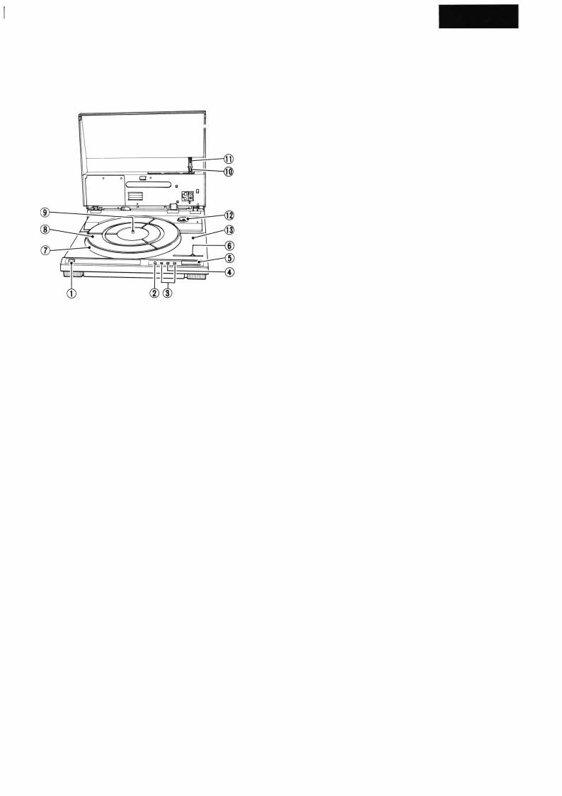
3. FRONT PANEL FACILITIES
--"'-----@
CD POWER switch
Press this switch to turn the power on and off. [ON) (depressed position) : Power is switched ON.
[STAND-BY] (released position): Power is switched OFF.
® REPEAT switch/indicator
Press this switch so that the indicator lights for repeat play.
@ LOCATE switches
Use these switches to start manual playback, or during playback to change the track being played. When the switches are pressed, the tonearm will move to the right or left.
[...,....,.): Tonearm moves to left. [.,..,.I: Tonearm moves to right.
@ARM ELEVATION switch(UP)/ indicator
•Use the switch for manual play.
•Use the switch to suspend record play temporarily.
•Use the switch when changing the tracks during manual play.
[UPI indicator lights:
The tonearm rises (the stylus moves away from the record). [UPI indicator goes out:
The tonearm descends (the stylus is lowered onto the record).
@ START/STOP switch
Depress this switch when starting auto play or when stop ping play.
@ SPEED switch
Set this switch in accordance with the speed of the record which is to be played.
[AUTO]: Automatically sets rotation speed in accordance with the size of the record: Rotates at 33-1/3 rpm with 30 cm records. Rotates at 45 rpm with 17 cm records.
Rotates at 33-1/3 rpm
Rotates at 45 rpm
(J)Platter
®Rubber mat
®Platter shaft
@Tonearm
@CARTRIDGE (PC-300T)
NOTE:
A cartridge is not provided with the KUT and KCT mode/1 and so your own cartridge should be mounmd, following th• instructions laid down in CARTRIDGE MOUNTING.
@l EP adapter
This is used when playing records with a "large center hole".
@Cabinet
@Dust cover
4

PL-L50
4. BLOCK DIAGRAM |
+B1 |
|
|
||
|
|
RESET Cl |
|
|
|
|
C7 tt |
|
|
|
Rl2 |
|
+ |
|
PHONO MOTOR CIRCUIT |
|
|
ADRIVING AMP
BHALLAMP
c V-1 CONVERTER
D.DRIVING AMP
E |
RESET CIRCUIT |
- |
F |
SAMPLE ,S HOL D |
CIRCUIT |
G |
VOLTAGE REGULATOR |
|
HBUFFER AMP FG AMP
TIMING Cl RCUIT
KPHASE COMPARATOR
L |
LOCK |
INDICATOR |
1 |
|
|
|
|
|
|
|
|
M |
l/2 |
VCC2 |
CIRCUIT |
+B (12Vl |
|
|
|
|
|
+B2(5Vl |
|
POWER |
SUPPLY |
CIRCUIT |
|
|
|
|
|
|
|
|
05 |
+
C4
5

ARM RESET SWITCH
QI PD6033
3RESET
ADDRESS SENSOR CIRCUIT
S I
-0
S 2
-0
S3
-0
S4
-0
S5
-0
33
AUTO
45
(1/2)
1 (2/2)
21S/S
I>
EV
<l
REP
16 33 rpm
15 |
45 |
rpm |
33 /45
PHMOTOR
ARM I>
ARM <l
EV I
EV 2
03 M54547P
e
ADDRESS 26
SIZE DETECTOR CIRCUIT
17 SIZE 25
30 SIZE 24
09
REP LED
UP LED
LED DRIVER
06 (REP)
+ 82
D71UP)
COVER 0/C DETECTOR SWITCH
ARM DRIVING |
TRACKING |
SENSOR CIRCUIT |
|||
5v-----.------- w.. -, |
|||||
MOTOR |
0201 |
r |
|
||
+ 81 |
I |
I |
|||
|
|
: |
|
:I |
|
|
|
I |
|||
|
|
I |
I |
||
|
|
L_ |
_...J |
||
0201 |
|
|
|
|
|
VR201 |
TRACKING |
||||
|
|||||
|
|
|
|
SENSOR |
|
GAIN
ADJ
6
5.CIRCUIT DESCRIPTIONS
5.1CIRCUIT DESCRIPTIONS
5.1.1 Address Sensor Circuit
The address sensor is located on the mechanism base unit. It detects the position of the tonearm and sends ad dress pulses to the control IC as the tonearm moves. The address sensor is made up of an internal schmitt trigger circuit photo interrupter and a slit wheel which is syn chronized with the carriage. The slit wheel spins when the carriage moves and intermittently cuts off Iight to the photo interrupter (0301) in pulses which correspond to the carriage movement. These pulses are counted by the control IC, which detects the distance the carriage moves, the tonearm lowering position and the end of the record. It also registers band addresses.
The address pulses from the photo interrupter work as follows: When the light is cut off, the output is "L," and when the .:ight is not cut off the output is "H." One address signal pulse is approximately equivalent to 0.114 mm of tonearm movement.
PD6033 |
: |
Voltage regulator |
|
1 |
r-A, I |
||
QI |
|
|
|
|
|
-- ------------ |
|
|
+sv --<.--+ |
w.r.--, |
|
ADDRE ___,,,. l--..--- ,,- ___ !- _j
}- Photo interrupterj' Slit wheel
Fig. 5-1 Address Sensor Circuit
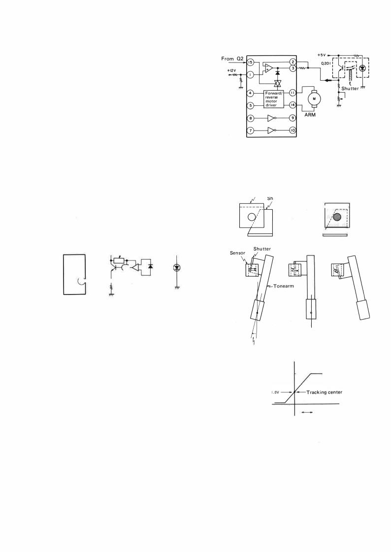
5.1.2 Tracking Sensor Circuit
This circuit detects tracking errors by means of a shutter which is synchronized with the tonearm and a photo in terrupter.
The tracking sensor is made up of a shutter synchro nized with the tonearm and a photo interrupter which is mounted onto the carriage base board. When the tonearm lowers and begins tracing the record surface the tonearm tracking errors increase as the number of rpms increases. When tracking errors increase, the shutter, which is syn chronized with the tonearm, also moves and the light cut off rate of the photo interrupter changes. Subsequently, the output of the photo interrupter changes and is sent to the tonearm drive unit in the form of tracking error signals.
Q3 M54547P
VR201
Tracking sensor gain ADJ
drive motor
Fig. 5-2 Tracking sensor circuit
Sensor
utterr71 ------
J I
Tracking error
3V ------
o |
Tracking error |
|
Small Large |
Fig. 5-3 Detection of tracking errors.
7

5.1.3 Elevation and Tonearm Circuits
The tonearm drive motor and EV solenoid are controlled by commands from the control IC (01), which also con trols the horizontal and vertical movement of the tonearm. In addition to this, the IC controls tonearm tracking with the tracking sensor and tracking error signals.
•EV solenoid drive
The EV solenoid drive uses a large current at first to
draw the plunger inside, and thereafter uses a lower current for holding the plunger in.
The signal to draw the plunger inside comes from the control IC (01), passes through the 02 transistor array, and enters 03 pin 8. This signal turns on the 03 Darlington transistor, and approximately 170mA of current runs into the collector, turning on the EV solenoid which draws the plunger inside. Because of this, the tonearm will drop slightly. This "draw" signal from the control IC lasts about 1 second. Next, the hold signal, which was output at the same time as the draw signal, passes through the 02 tran sistor array, enters 03 pin 7 and turns on the Darlington transistor. When the draw signal ends, a current of ap proximately 70mA drawn from pin 10 holds the plunger inside, which keeps the tonearm elevation down until the hold signal ends.
• Tonearm drive
The tonearm drive is controlled by input to 03 pin 4, pin 5, and pin 15. Their truth values are shown in Fig. 5-4
• Lead-in (locate-in)
03 receives locate-in signals from the control IC (01), and with an output of approximately OV from 03 pin 14 (01) and approximately 11V from pin 11 (02), the tone arm motor begins turning in the lead-in direction.
• Lead-out (locate-out)
03receives locate-out signals from the control IC (01). and with an output of approximately 11V from pin 14 and approximately OV from pin 11, the tonearm motor begins turning in the lead-out direction.
•Stop
03receives stop signals from the control IC (01), and with an output of approximately OV from both pin 14 and pin 11, stops the tonearm motor.
•Tracking
03receives tracking signals from the control IC (01), and between pin 14 and pin 11, outputs an amplified tracking error signal (amplified by an internal OP am plifier) and begins turning the tonearm drive motor in such a way as to correct the error.
+ 12V |
|
Q3: M54547P |
+ : Pull up resistor |
QI
EV solenoid
|
|
|
|
' |
I |
|
|
|
|
|
|
|
|
• |
|
|
|
|
|
|
STOP ! |
|
|
|
|
|
|
|
|
EV SW ON |
|
||
|
|
.... .... |
|
Tracking [ |
|
Input |
|
Output |
|
|
|
|||||
|
|
|
|
|
|
|
|
|
||||||||
t |
I |
I |
I |
|
|
|
|
Tonearm |
|
-i--:- I SEC |
||||||
|
|
|
|
|
|
|
|
|
|
|
||||||
0 |
.. IN .... IN |
|
SW |
01 |
02 |
operation |
|
|
||||||||
© |
® |
|
@ |
@) |
@ |
|
|
|||||||||
|
|
|
|
|
||||||||||||
L |
H |
|
L |
|
L |
Lead-out |
... |
0-i___r- |
||||||||
|
H |
|||||||||||||||
H |
L |
|
L |
L |
H |
Lead-in |
- |
@-u-T |
||||||||
|
|
|
|
|
|
|
|
|
|
|||||||
|
|
L |
: |
L Ii |
|
|
|
|
|
|
|
|
|
|
||
|
|
|
|
|
|
|
|
|
|
|
|
|||||
|
|
|
|
|
|
|
|
|
|
|
|
|||||
® I I I , |
|
|
|
|
|
|
|
|
' |
' |
||||||
|
|
|
|
|
|
|
|
|||||||||
I |
I |
I |
: |
H |
H |
H |
L |
L |
L |
Stop |
|
:down |
i up |
|||
© I |
|
|
|
|
|
|
||||||||||
|
|
|
|
|
|
|
|
|
|
|
|
|
|
|
:Tonearm: Tonearm |
|
|
|
|
|
|
|
|
L |
L |
H |
L |
H |
Tonearm tracking |
|
|
||
|
|
|
|
|
|
|
|
|
||||||||
|
|
|
|
|
|
|
|
|
|
|
|
|
|
|
|
|
Fig. 5-4 Elevation and Tonearm Drive Circuit and 1/0 Truth Value Chart.
B

5.1.4 Seize Detector Circuit
The size detector is made up to three slits for detecting 30 cm records, three slits for detecting 17 cm records, and two LEDs and two photo transitors. It detects the record size by detecting the existence of LED light passing through the slits.
• When there is no Record
Light from LED 0301 (for 30 cm) goes through the slits in the turntable and rubber sheet and strikes photo transistor 082. 082 goes ON and OFF according to the revolutions of the turntable. In the same way, the light from 0302 (for 17 cm) strikes 081, and 081 ON and OFF.
When 082 (081) turns on, 09 (08) also turns on and that output goes to the 01 pin 24 which is the 30 cm rec ord size pin (pin 25 is the 17 cm record size pin). 01 deter mines that there is no record.
• When there is a 17 cm Record
When the 17 cm record size slits are covered by a record, 081 turns off, and 080 remains off. Due to this, "H" is input into 01 pin 25. When the 30 cm record size slits are not covered, it's the same as no record, and 082 and 09 go ON and OFF according to the revolutions of the turn table. The waveforms show in figure are then input into 01 pin 24. 01 then determines that there is a 17 cm record because of this.
• When there is a 30 cm Record
Since the 17 and 30 cm record size slits are both cover ed, 081, 08, 082, and 09 all turn off. 01 pins 24 and 25 both receive "H" input, and because of this 01 determines that there is a 30 cm record.
• When there is no Record |
• When there is a 70 cm Record |
©: =u= |
---H |
@: ------ L |
|
@:=ic: |
@:==1e: |
|
Fig. 5-5 @. @ point wave pattern |
• When there is a 30 cm Record
---H @: ______ L
@: -_-_-_- - -_
r |
----------- ------- -------- |
-, |
||
|
MEC HANISM BASE |
|||
I |
5V |
I |
||
II |
5V B OARD ASSEMBLY |
: |
||
II |
R 02 |
R3030301 |
---II |
|
II |
|
I |
||
|
II |
|||
: |
SLH-56VC3H-T |
SLH·56VC3H-T |
|
I |
d™™j)\)+)))§§5,)))IDf |
|
|
|
||||
r---------------- --------------- |
|||||||
I |
Q 81 |
5V |
Q82 |
Ph |
T |
s i |
: |
II 5V |
PHI Ol·R |
PH I O I-R |
|
A J |
|
I |
|
L_ --- -- |
|
|
|
|
|
|
|
FOR QI P@)
L------------ |
----- FOR QI P@ |
V OLTAGE
( V) |
5 |
|
|
@,® POINT WAVE |
FORM |
|
|
4 |
,',---....\ |
|
|||
|
|
I |
\ |
,@PO INT WAVE FORM |
||
|
|
|
||||
|
2 |
I |
\ |
|||
|
, |
|
|
r.\ |
|
|
|
|
\/ |
|
|
||
|
II, |
|
' ' |
|
|
|
|
oL- ....1..J.....:::===:::c=:::: L.i --'- -- |
|||||
|
10 |
20 |
30 |
40 |
TIME |
t |
( mStc)
Fig. 5-6 Size Detector Circuit
9

5. 1.5 Phono Motor Circuit
The phono motor of this player uses magnetism along the outside edge of the drive magnet to determine its rpm value. (Formerly, a separate magnet was needed in addition to the drive magnet.)
This motor uses a PA2017 as its control drive IC. Also, since this motor is brushless and coreless, the position of the rotor magnet is detected by two Hall elements HA and HB, which make the motor turn by switching the current to the drive coil electronically. When voltage is applied to the Hall elements HA and HB, a voltage differential is created in the output i_nterval by the magnetic field of the approaching rotor. The Hall elements HA and HB are also attached 90° electrically out of phase so their output sig nals have a 90° phase difference. (See Fig. 5-13)
After the output voltage from the Hall elements have been amplified by the PA2017 Hall amplifier, it enters a position signal composite circuit (See Fig. 5-15). The output from the position signal composite circuit is then input into the respective drive amplifiers. The coil current at this time is as shown is figure 5-13 coils A and B. This
Pin 22 HA+
Pin 21 HA-
Pin 20 HB+
Pin 19 HB-
Coil A
Pin 1 waveform |
H |
seen with pin 2 |
0 |
as reference |
L |
Coil B |
H |
Pin 23 waveform |
0 |
seen with pin 24 |
L |
ys reference |
|
Fig. 5-7 Hall Elements and Coil Terminal Waveforms
current produces a magnetic field in the drive coil, and the polarity of the coil and the polarity of the rotor attract and repel each other causing the motor to start turning.
When the motor starts turning, the signal (approximately 0.5mV p-p) produced by a frequency generator (FG) in
the mtor rotation unit, is amplified to about 0.3V p-p by an FG amplifier (05, 06) and is input into the FG ampli
fier (input pin 17) inside PA2017. Possible frequencies at this point are 55.55 Hz for 33 rpm and 75 Hz for 45 rpm.
The signal then undergoes waveform shaping in the Schmitt transistor, and is then input into the reset circuit, the sample and hold circuit and finally the timing circuit for a timing pulse for the phase comparison circuit. In the Signals are input into the reset circuit and the sample and hold circuit, and undergo F - V conversion (pin 8). The signals are then amplified by the buffer amplifier and then input into the V - I conversion circuit. The V - I con version circuit controls the current that flows into the drive circuit based on the difference between the output of the
buffer ampIifier and the referance voltage (1/2VCC2).
Drive. c1rcu1t. . current t
0
+
Voltage between pin 10 and pin 11
Fig. 5-8 V - I Conversion+ Drive Circuit 1/0 Characteristics
When the motor has just begun truning, the F - V conversion voltage will be higher than the reference voltage, so current will flow into the drive coil, and the motor will speed up. Gradually, the motor will return to a constant rotation speed.
When the motor spins faster than regulation speed, both the P - V and F - V conversion voltage become lower than the reference voltage. This causes the current to stop flowing in the drive circuit and the rpms decrease because of a loss of torque.
10
vcc
11-13\I
|
|
-------------------""J-l-+-,w.. |
0 331/3 : H (OPEN) |
|
|
|
45 ; L |
|
|
-------------------------------------- |
0: T: (OPENJ |
|
Fig. 5-9 Phono Motor Circuit
|
|
(Approximately 0.3V p-p) |
|
3.6V |
|
|
A ,C\_ |
A |
|
|
|
A |
l.7V |
Pin 6 |
|
||
|
|
|
|
|
ov |
|
|
|
3.7V |
|
|
Pin 16 |
|
|
|
Pin 8 |
|
|
|
|
|
|
|
|
|
|
2.3 V |
|
|
|
|
|
|
Pin 10 |
3.6V |
7.1 V
Pin 15
o v
Fig. 5-10 Phono Motor Circuit Waveforms
11

IC (PD6033) terminal descriptions
Pin |
Symbol |
1/0 |
Terminal name |
Description |
|
|
|
|
|
|
|
|
|
|
|
No. |
display |
|
|
|
|
|
|
|
|
|
|
||||
|
|
|
|
|
|
|
|
|
|
|
|
|
|
||
|
|
|
|
|
|
|
|
|
|
|
|
|
|
|
|
1 |
EXtaI |
-- |
|
Internal clock oscillator external circuit terminal |
|
|
|
|
|
|
|
|
|
|
Ceramic oscil- |
2 |
Xtal |
|
|
|
|
|
|
|
|
|
|
|
|
lator "3MHz" |
|
|
|
|
|
|
|
|
|
|
|
|
|
|
|||
|
|
|
|
|
|
|
|
|
|
|
|
|
|
||
3 |
Reset |
I |
|
CPU initial reset input |
|
|
Normally "H" |
||||||||
4 |
00 |
0 |
ARM I> |
Tonearm motor drive output (toward outside edge) |
|
|
|
|
|||||||
5 |
01 |
0 |
ARM <l |
Tonearm motor drive output (toward center) |
|
|
|
|
|
||||||
6 |
02 |
0 |
EV 1 |
Tonearm EV drive output (drawing plunger in) |
|
|
|
ON I |
OFF |
Drawing time |
|||||
|
|
|
1 sec |
||||||||||||
|
|
|
|
|
|
|
|
|
|
|
|
|
|
|
|
7 |
03 |
0 |
EV 2 |
Tonearm EV drive output (holding plunger in) |
|
|
|
ON I |
OFF |
|
|||||
8 |
04 |
0 |
TRACKING |
Tonearm tracking output during tracing |
|
|
|
ON |
I |
OFF |
|
||||
9 |
05 |
0 |
33/45 |
Phono motor 33/45 switch output |
|
|
- |
|
|||||||
10 |
06 |
0 |
PHONO-MOTOR |
Phono motor START/STOP output |
|
|
Start |
i |
Stop |
|
|||||
11 |
Q7 |
|
|
|
|
|
|
|
|
|
|
|
|
|
|
12 |
RO |
I |
0/C |
Cover 0/C detection input |
|
|
Open i |
Closed |
|
||||||
13 |
Rl |
-- |
|
|
|
|
|
|
|
|
|
|
|
|
|
14 |
Vss |
|
GND |
|
|
|
|
|
|
|
|
|
|
|
|
15 |
R2 |
I |
45rpm |
33/45 switch 45 input |
|
Closed i |
AUTO |
|
|||||||
|
|
|
|
|
|
|
|
|
|
|
|
|
|
||
16 |
R3 |
I |
33rpm |
33/45 switch 33 input Tonearm START/STOP switch in ut |
I |
AUTO |
|
||||||||
17 |
R4 |
I |
REP |
Repeat switch input |
|
|
|
ON I |
OFF |
|
|||||
18 |
R5 |
I |
<l |
Locate switch input (toward record center) |
|
|
|
ON |
I |
OFF |
|
||||
19 |
R6 |
I |
EV |
Tonearm elevation switch input |
|
|
|
ON |
I |
OFF |
|
||||
20 |
R7 |
I |
I> |
Locate switch input (Toward outside edge) |
|
|
|
ON I |
OFF |
|
|||||
21 |
R8 |
I |
SIS |
Tonearm START/STOP switch input |
|
|
|
ON |
I |
OFF |
|
||||
|
|
|
|
|
|
|
|
|
|
|
|
|
|
||
22 |
R9 |
0 |
UP LED |
Tonearm UP display LED output |
|
|
|
|
UP |
I |
DOWN |
|
|||
23 |
R10 |
0 |
REP LED |
Repeat display LED output |
|
|
|
ON |
I |
OFF |
|
||||
24 |
KO |
I |
30 SIZE |
30 cm record detector input |
|
|
|||||||||
25 |
Kl |
I |
17 SIZE |
17 cm record detector input |
|
|
|||||||||
26 |
K2 |
I |
ADDRESS |
Address sensor input |
|
|
|
-11.Iu |
|
||||||
27 |
K3 |
I |
REST |
Rest switch input |
|
On rest |
I |
Off rest |
|
||||||
28 |
Vee |
-- |
|
+5V |
|
|
|
|
|
|
|
|
|
|
|
|
|
|
|
|
|
|
|
|
|
|
|
|
|||
|
|
|
|
|
|
|
|
|
|
|
|
|
|
|
|
12

17cm EP Fully automatic playing
|
|
|
|
|
Place 17cm |
|
|
|
|
|
|
Cover open |
record on |
Cover closed |
|
|
|
||
|
|
turntable. |
|
START/STOP |
|
||||
|
|
|
|
|
1 |
|
|
ON |
|
|
|
|
|
|
|
|
" |
|
|
Power on |
|
|
|
|
|
Fully automatic |
|
|
|
|
|
|
|
|
|
playing starts. |
|
|
|
|
|
|
|
|
|
|
|
|
|
|
|
|
Initial reset |
|
|
|
|
|
|
|
o |
Tonearm at rest |
|
|
|
Turntable |
. |
||
|
o |
Phono motor stationary |
|
|
(33rpm) |
|
|||
|
|
|
|
||||||
|
0 |
Cover closed |
|
|
|
|
|||
' I , |
o Speed switch set to AUTO position. |
|
|
|
|
||||
-0- - U |
LE |
N------------------------------- |
|||||||
,, I ' |
|
P |
D O |
|
|
|
|
|
|
|
|
|
|
|
|
|
|
|
|
01 logic in initial reset complete status |
|||||
I |
- |
8 |
H |
15 |
|
|
|||||
2 |
- |
9 |
H |
16 |
|
H |
|||||
3 |
10 |
H |
17 |
||
4 |
H |
11 |
H |
18 |
|
5 |
H |
12 |
- |
19 |
|
|
|||||
6 |
H |
13 |
H |
20 |
|
7 |
H |
14 |
L(GND) 21 |
||
|
|||||
H When on AUTO or 33 rpm
H When on AUTO or 45 rpm
H When the-switch··-is not pressed:
H
H-,,-
H-,,-
H_,,_
22 |
L |
|
23 |
H |
Tur |
24 |
- |
|
|
|
|
25 |
- |
|
|
|
26-
27L
285V
Detects end |
Tonearm |
of record |
up |
Automatic return
Detects |
EV solenoid |
' |
|
end of record |
|
|
0I |
L------OFF |
1 |
||
|
' - |
/I |
- - - - - - - - - - - - - - - - - - - - - - - - - |
-0- |
|
|
.... I' |
|
|
I |
|
|
I |
|
|
I |
|
|
I |
|
|
I |
|
|
I |
|
Playing selection |
I |
.,,...... .,,,.-- |
|
|
|
./
u?
.,,,.....,..
13

ects no |
|
|
m record. |
Lead-in |
|
ects 17cm |
||
|
||
ird. |
|
|
|
v |
3Tonearm moves toward record center.
|
Tonearm |
|
returns |
J |
|
, |
|
Turntable stops turning. |
|
Tonearm moves toward |
|
outside edge of records. |
|
_,,,., |
_,,, |
I |
|
||
|
|
I |
|
|
I |
|
|
I |
|
|
I |
|
For model number PL-L50 |
|
|
|
|
Tonearm position |
|
Player operation |
Sensor Detection |
during operation |
Unit operations |
|
Tonearm DOWN |
|
|
|
|
Tracing |
|
|
j |
|
|
|
|
|
|
|
I' |
|
|
ii' |
|
|
I |
I |
|
|
|
|
|
|
I |
|
|
|
|
|
|
|
I |
|
|
|
|
|
|
|
I |
17cm lowering |
Tonearm stops, |
Tonearm |
|
I |
|||
|
EV solenoid |
------- '------- |
|||||
position address |
|
|
|
|
|
|
I |
|
drawn in |
|
ON |
|
|
I |
|
|
+ |
|
|
|
|
|
I |
L--------.. |
|
|
|
|
|
||
|
|
UP LED OFF |
|
|
|
|
|
|
I |
|
|
|
|
|
I |
|
I |
|
|
|
|
|
I |
|
1-. |
-........ |
|
|
|
|
I |
|
I |
|
|
|
|
|
|
|
I |
........_ Dow |
ft/ |
|
|
|
'1 |
|
........_ |
|
|
|
|||
|
I |
' |
|
|
|
I |
|
|
|
-........ |
......_ |
|
|
I |
|
|
I |
|
|
-........ |
|
||
|
|
|
......_ |
I |
|||
|
I |
|
|
|
|
||
|
|
|
|
|
|
.f\..f\_f\J"\J' |
|
|
Detects |
|
rest |
|
I |
|
+t |
Rest |
Tonearm stops |
L------, |
|
|
I |
|
I |
|
I |
|
I |
|
I |
|
I |
|
I |
|
I |
|
, |
|
I |
14
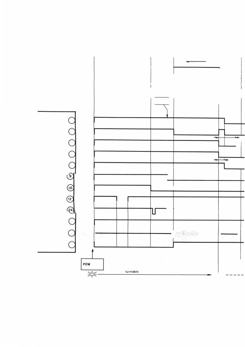
Timing chart
17cm EP fully automatic operation |
1 cycle |
|
|
|
|
|
|
|
|
-C,- Speed switch set to AUTO |
|
|
|
|
|
|
|
|
|
--------- - |
- |
|
I |
|
|
||||
|
|
|
£ |
|
c:;:i |
|
|
|
|
|
|
- |
|
-[QJ |
|
|
|
|
-"' |
|
|
'4E-R o,dsi |
|
|
|
|
|||
|
|
|
Lead-in _j_ -- |
||||||
|
|
|
detection |
|
Arrival at 17cm |
Tonea, |
|||
|
Turntable |
Lead-in |
|
||||||
|
rpms |
|
begins |
|
lowering position |
down |
|||
|
|
|
17cm |
|
|
|
|
|
|
|
|
(detection) |
|
|
|
|
|
||
ARM I> |
4 |
ARM <] |
5 |
EV1 |
6 |
(Drawing plunger in) |
|
EV2 |
7 |
(Holding plunger in) |
|
TRACKING |
8 |
33/45 |
|
PHONO-MOTOR |
|
o/c
30 SIZE
17 SIZE |
25 |
ADDRESS 26
REST 27
|
|
|
|
<l<l |
|
|
|
|
|
|
,--!: |
|
|
|
|
EV |
|
|
|
|
|
DOWN |
|
|
|
|
|
I |
Approxim; |
|
|
|
|
|
tracking O |
|
|
|
I |
45rpm set |
|
|
|
|
Turntable turns |
|
|
|
....._ |
|
|
|
|
|
|
|
lf1J1f1Jl1lf------ |
---- - |
|
|
|
|
|
||
|
|
|
|
UJUUlJUlJUlJ--------- |
L |
|
t |
f |
|
|
|
ER ON |
Cover |
Cover |
|
|
|
|
open |
closed |
N |
|
|
|
Record placed on |
cb |
• |
|
|
15
 Loading...