


This file was downloaded and provided FREE OF CHARGE from the ManualDirectory community.
You can find many free to download Service Manuals & Schematics at
http://www.manualdirectory.co.uk

GM-X1024/X1R/UC
Service
Manual |
CRT2191 |
|
ORDER NO. |
BRIDGEABL FOUR-CHANNEL POWER AMPLIFIER
GM-X1024 X1R/UC
GM-X924 X1R/UC,EW,ES
CONTENTS
1. |
SAFETY INFORMATION ............................................ |
2 |
7. |
GENERAL INFORMATION ....................................... |
26 |
2. |
EXPLODED VIEWS AND PARTS LIST ....................... |
2 |
|
7.1 IC ........................................................................ |
26 |
3. |
SCHEMATIC DIAGRAM ............................................. |
8 |
|
7.2 DISASSEMBLY ................................................... |
27 |
4. PCB CONNECTION DIAGRAM ................................ |
14 |
|
7.3 BLOCK DIAGRAM .............................................. |
28 |
|
5. |
ELECTRICAL PARTS LIST ........................................ |
19 |
8. |
OPERATIONS AND SPECIFICATIONS..................... |
29 |
6. ADJUSTMENT.......................................................... |
25 |
|
|
|
|
|
|
|
|||
PIONEER ELECTRONIC CORPORATION |
4-1, Meguro 1-Chome, Meguro-ku, Tokyo 153-8654, Japan |
|
|||
PIONEER ELECTRONICS SERVICE INC. P.O.Box 1760, Long Beach, CA 90801-1760 U.S.A. |
|
||||
PIONEER ELECTRONIC [EUROPE] N.V. Haven 1087 Keetberglaan 1, 9120 Melsele, Belgium
PIONEER ELECTRONICS ASIACENTRE PTE.LTD. 501 Orchard Road, #10-00, Lane Wheelock Place, Singapore 23880
C PIONEER ELECTRONIC CORPORATION 1998
K-FED. MAR. 1998 Printed in Japan
GM-X1024,GM-X924
1. SAFETY INFORMATION
CAUTION
This service manual is intended for qualified service technicians; it is not meant for the casual do-it-yourselfer. Qualified technicians have the necessary test equipment and tools, and have been trained to properly and safely repair complex products such as those covered by this manual.
Improperly performed repairs can adversely affect the safety and reliability of the product and may void the warranty. If you are not qualified to perform the repair of this product properly and safely; you should not risk trying to do so and refer the repair to a qualified service technician.
WARNING
Lead in solder used in this product is listed by the California Health and Welfare agency as a known reproductive toxicant which may cause birth defects or other reproductive harm (California Health and Safety Code, Section 25249.5). When servicing or handling circuit boards and other components which contain lead in solder, avoid unprotected skin contact with the solder. Also, when soldering do not inhale any smoke or fumes produced.
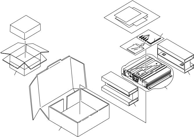
2. EXPLODED VIEWS AND PARTS LIST
2.1 PACKING
 10
10
3 |
2 |
5 |
4
8 |
9 |
6
9
7
Fig. 1
2
GM-X1024,GM-X924
NOTE:
-Parts marked by “*”are generally unavailable because they are not in our Master Spare Parts List.
-Screws adjacent to mark on the product are used for disassembly.
(1) PACKING SECTION PARTS LIST
Mark No. Description |
Part No. |
|
Mark No. Description |
Part No. |
||||
|
|
|
|
|
|
|
|
|
|
1 |
••••• |
|
|
|
6 |
Polyethylene Bag |
HEG0013 |
* |
2 Screw Assy |
HEA0044 |
|
|
7 |
Carton |
See Contrast table (2) |
|
|
3 |
Screw |
BYC40P180FZK |
|
|
8 |
Contain Box |
See Contrast table (2) |
|
4 |
Polyethylene Bag |
HEG0011 |
|
|
9 |
Protector |
HHP0025 |
|
5 |
Wrench |
HLP0001 |
|
|
10-1 |
Owner's Manual |
See Contrast table (2) |
|
|
|
|
* |
10-2 |
Card |
See Contrast table (2) |
|
|
|
|
|
* |
10-3 |
Warranty Card |
See Contrast table (2) |
|
|
|
|
|
|
|
10-4 |
Owner's Manual |
See Contrast table (2) |
(2) CONTRAST TABLE
GM-X1024/X1R/UC, GM-X924/X1R/UC, GM-X924/X1R/EW and GM-X924/X1R/ES are constructed the same except for the following:
|
|
|
|
|
Part No. |
|
|
|
|
|
GM-X1024 |
|
|
GM-X924 |
|
Mark |
No. |
Symbol and Description |
X1R/UC |
X1R/UC |
|
X1R/EW |
X1R/ES |
|
7 |
Carton |
HHG0154 |
HHG0155 |
|
HHG0158 |
HHG0157 |
|
8 |
Contain Box |
HHL0154 |
HHL0155 |
|
HHL0158 |
HHL0157 |
|
10-1 |
Owner’s Manual |
HRD0056 |
HRD0057 |
|
HRD0059 |
HRD0058 |
* |
10-2 |
Card |
Not used |
ARY1048 |
|
Not used |
Not used |
* |
10-3 |
Warranty Card |
HRY1070 |
Not used |
|
HRY1087 |
Not used |
|
10-4 |
Owner’s Manual |
Not used |
Not used |
|
Not used |
HRD0068 |
- Owner's Manual
Model |
Part No. |
Language |
|
|
|
GM-X1024/X1R/UC |
HRD0056 |
English, French |
|
|
|
GM-X924/X1R/UC |
HRD0057 |
English, French |
|
|
|
GM-X924/X1R/EW |
HRD0059 |
English, French, German, Dutch, Spanish, Italian |
|
|
|
GM-X924/X1R/ES |
HRD0058 |
English, Spanish |
|
|
|
|
HRD0068 |
Arabic, Poltuguese (B) |
|
|
|
3
GM-X1024,GM-X924
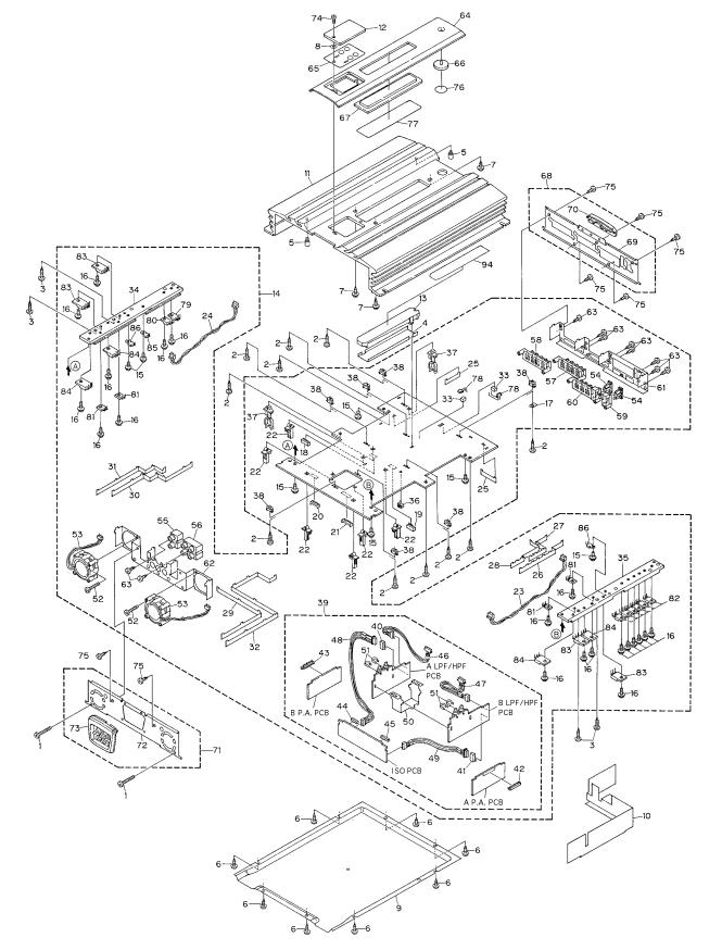
2.2 EXTERIOR
Fig. 2
4
GM-X1024,GM-X924
(1) EXTERIOR SECTION PARTS LIST
Mark No. Description |
Part No. |
|
Mark No. Description |
Part No. |
||
|
|
|
|
|
|
|
1 |
Screw(M3×25) |
HBA0013 |
46 |
Cord(CN502) |
HDE5501 |
|
2 |
Screw(M3×12) |
CBA1323 |
47 |
Cord(CN552) |
HDE5501 |
|
3 |
Screw(M3×14) |
CBA1382 |
48 |
Cord(CN854) |
HDE5501 |
|
4 |
Sheet |
CNM5852 |
49 |
Cord(CN855) |
HDE5501 |
|
5 |
Screw(M3×5) |
HBA0006 |
50 |
Holder |
HNC0029 |
|
6 |
Screw(M3×8) |
HBA0011 |
51 |
Clip |
HNC0054 |
|
7 |
Screw(M2.6×6) |
HBA0012 |
52 |
Screw(M3×25) |
HBA0013 |
|
8 |
Washer |
HBF0005 |
53 |
Fan Motor |
CXM1102 |
|
9 |
Case |
HNB0036 |
54 |
Fuse |
HEK0030 |
|
10 |
Separator |
HNM0046 |
55 |
Pin Jack(CN801) |
HKB0002 |
|
11 |
Heat Sink |
See Contrast table (2) |
56 |
Pin Jack(CN851) |
HKB0004 |
|
12 |
Window |
HNS0053 |
57 |
Terminal(CN101) |
HKE0010 |
|
13 |
Lighting Conductor |
HNV0012 |
58 |
Terminal(CN301) |
HKE0010 |
|
14 |
Amp Unit |
See Contrast table (2) |
59 |
Fuse Holder(CN902) |
HKE0012 |
|
15 |
Screw |
BMS30P060FZK |
60 |
Terminal(CN901) |
HKE0014 |
|
16 |
Screw |
BMS30P080FMC |
61 |
Holder |
HNC0027 |
|
17 |
Terminal(CN905) |
CKF1059 |
62 |
Holder |
HNC0028 |
|
18 |
Plug(CN503) |
CKS1039 |
63 |
Screw |
PPZ30P060FZK |
|
19 |
Plug(CN553) |
CKS1039 |
64 |
Plate Unit |
See Contrast table (2) |
|
20 |
Connector(CN853) |
CKS3813 |
65 |
Sheet Unit |
See Contrast table (2) |
|
21 |
Connector(CN852) |
CKS3814 |
66 |
Light Pipe Unit |
HXA0201 |
|
22 |
Holder |
CNV4017 |
67 |
Plate Unit |
See Contrast table (2) |
|
23 |
Cord(CN104) |
HDE5500 |
68 |
Panel Unit |
See Contrast table (2) |
|
24 |
Cord(CN304) |
HDE5500 |
69 |
Panel |
See Contrast table (2) |
|
25 |
Bass Bar |
HNC0043 |
70 |
Plate |
See Contrast table (2) |
|
26 |
Bass Bar |
HNC0044 |
71 |
Panel Unit |
See Contrast table (2) |
|
27 |
Bass Bar |
HNC0046 |
72 |
Front Panel |
See Contrast table (2) |
|
28 |
Bass Bar |
HNC0047 |
73 |
Plate |
See Contrast table (2) |
|
29 |
Bass Bar |
HNC0049 |
74 |
Screw |
SMZ30H080FCR |
|
30 |
Bass Bar |
HNC0050 |
75 |
Screw |
BSZ30P050FZK |
|
31 |
Bass Bar |
HNC0052 |
76 |
Film |
See Contrast table (2) |
|
32 |
Bass Bar |
HNC0055 |
77 |
Film |
See Contrast table (2) |
|
33 |
Spacer |
HNM0053 |
78 |
LED(D903,904) |
NSPWF50S(AQ) |
|
34 |
Heat Sink |
HNR0079 |
79 |
Diode(D961) |
FML22R |
|
35 |
Heat Sink |
HNR0080 |
80 |
Diode(D962) |
FML22S |
|
36 |
Clamper |
HNV0003 |
81 |
Transistor(Q112,212,312,412) |
2SC1568 |
|
37 |
Clamper |
HNV0015 |
82 |
FET(Q963–968) |
IRFIZ44N |
|
38 |
Spacer |
HNV3975 |
83 |
Transistor(Q115,215,315,415) |
2SC5101 |
|
39 |
Network Unit |
See Contrast table (2) |
84 |
Transistor(Q116,216,316,416) |
2SA1919 |
|
40 |
Plug(CN501) |
CKS1039 |
85 |
Thermistor(TH901) |
CCX1027 |
|
41 |
Plug(CN551) |
CKS1039 |
86 |
Thermistor(TH902,903) |
CCX1035 |
|
42 |
Plug(CN102) |
CKS1621 |
87-93 |
••••• |
|
|
43 |
Plug(CN302) |
CKS1621 |
94 |
Sheet |
CNM5950 |
|
44 |
Connector(CN857) |
CKS3815 |
|
|
|
|
45 |
Connector(CN856) |
CKS3816 |
|
|
|
|
5
GM-X1024,GM-X924
(2) CONTRAST TABLE
GM-X1024/X1R/UC, GM-X924/X1R/UC, GM-X924/X1R/EW and GM-X924/X1R/ES are constructed the same except for the following:
|
|
|
|
Part No. |
|
|
|
|
GM-X1024 |
|
|
GM-X924 |
|
Mark No. |
Symbol and Description |
X1R/UC |
X1R/UC |
|
X1R/EW |
X1R/ES |
11 |
Heat Sink |
HNR0073 |
HNR0093 |
|
HNR0093 |
HNR0093 |
14 |
Amp Unit |
HWH0066 |
HWH0067 |
|
HWH0064 |
HWH0065 |
39 |
Network Unit |
HWG0008 |
HWG0009 |
|
HWG0006 |
HWG0007 |
64 |
Plate Unit |
HXA0262 |
HXA0112 |
|
HXA0112 |
HXA0112 |
65 |
Sheet Unit |
HXA0264 |
HXA0116 |
|
HXA0116 |
HXA0116 |
67 |
Plate Unit |
HXA0205 |
HXA0202 |
|
HXA0202 |
HXA0202 |
68 |
Panel Unit |
HXA0249 |
HXA0244 |
|
HXA0244 |
HXA0244 |
69 |
Panel |
* HNB0064 |
HNB0038 |
|
HNB0038 |
HNB0038 |
70 |
Plate |
* HNS0064 |
HNS0039 |
|
HNS0039 |
HNS0039 |
71 |
Panel Unit |
HXA0251 |
HXA0247 |
|
HXA0247 |
HXA0247 |
72 |
Panel |
* HNB0066 |
HNB0043 |
|
HNB0043 |
HNB0043 |
73 |
Plate |
* HNS0065 |
HNS0046 |
|
HNS0046 |
HNS0046 |
76 |
Film |
CNM5856 |
CNM5949 |
|
CNM5949 |
CNM5949 |
77 |
Film |
CNM5853 |
CNM5948 |
|
CNM5948 |
CNM5948 |
6
GM-X1024,GM-X924
7
1 |
|
2 |
|
3 |
|
4 |
|
|
|
GM-X1024,GM-X924
3. SCHEMATIC DIAGRAM
3.1 OVERALL CONNECTION DIAGRAM(GUIDE PAGE)
A
Note: When ordering service parts, be sure to refer to “EXPLODED VIEWS AND PARTS LIST” or “ELECTRICAL
PARTS LIST”.
A-a
|
|
Large size |
|
|
A-a |
A-b |
SCH diagram |
|
|
B |
|
HPF |
||
|
|
|
||
|
|
-10dBm |
-7.7dBm |
|
|
|
|
-10.2dBm |
|
|
|
|
|
A-a |
A-b |
Guide page |
|
|
B |
|
|
C |
|
A-a |
A-b |
Detailed page |
||
|
HPF
2CH/4CH
2CH
4CH
ISOLATOR
D
C
-15.4V
+15.4V
-42.1V +42.1V -29.0V +29.0V
|
DC-AC INVERTER |
+15V REGULATOR |
RECTIFICATION |
|
-15V REGULATOR
D
8 A B C D
LPF
VR501:FREQUENCY
VR501:FREQUENCY
LPF
VR551:FREQUENCY
VR551:FREQUENCY
SWITCHING
CONTROL
3.9V |
14.4V |
3.9V |
0V |
|
3.8V |
14.4V |
1.8V |
5V |
|
5V |
|
2.4V |
2.2V |
2.4V |
0V |
S501:LPF/HPF
OFF
-14.4dB
OFF
S501:LPF/HPF
S551:LPF/HPF
OFF
OFF
S551:LPF/HPF
GM-X924/X1R/EW,
GM-X924/X1R/ES
BFC
H
L
6.5V
D903,D904:NSPWF50S(AQ)
1 |
2 |
3 |
4 |
5
E
F
THERMO DETECTOR / PROTECTOR OVER VOLTAGE DETECTOR / PROTECTOR MUTE CONTROL
REGULATOR CONTROL
0.1V |
|
3.2V |
|
0.3V |
0V |
|
0.2V |
5V |
14.4V |
0V |
14.2V |
0.2V |
10.7V |
0V |
14.4V |
6 |
|
7 |
|
8 |
|
|
GM-X1024,GM-X924
A
A-b
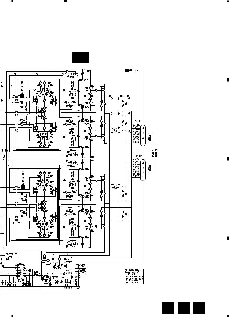
POWER STAGE
A
OVER CURRENT DETECTOR
B
20.4dBm
C
14.4V
D
Fig. 3
A E F 9
5 |
|
6 |
|
7 |
|
8 |
|
|
|
||||
|
|
|

A
B
C
D
1 |
|
2 |
|
GM-X1024,GM-X924
-14.4dBm
A-a A-b
S501:LPF/HPF |
OFF |
|
|
LPF |
VR501:FREQUENCY |
HPF
-10.2dBm
-7.7dBm
-10dBm
3 |
|
4 |
|
OFF |
S501:LPF/HPF |
S551:LPF/HPF |
OFF |
OFF |
S551:LPF/HPF |
|
LPF |
VR551:FREQUENCY |
VR501:FREQUENCY |
VR551:FREQUENCY |
HPF
ISOLATOR
2CH/4CH |
2CH |
4CH |
10 |
A-a B C D |
1 |
2 |
3 |
4 |
 Loading...