


Service
Manual
|
ORDER NO. |
GM-5100T/XU/EW |
CRT3369 |
BRIDGEABLE TWO-CHANNEL POWER AMPLIFIER
GM-5100T/XU/EW
GM-5100T/XU/UC
GM-5100T/XU/ES
GM-5100T/XU/CN
GM-510T/XU/UC
For details, refer to "Important check points for good servicing".
PIONEER CORPORATION |
4-1, Meguro |
1-Chome, Meguro-ku, Tokyo 153-8654, Japan |
PIONEER ELECTRONICS (USA) INC. |
P.O.Box 1760, Long Beach, CA 90801-1760 U.S.A. |
|
PIONEER EUROPE NV Haven 1087 |
Keetberglaan 1, |
9120 Melsele, Belgium |
PIONEER ELECTRONICS ASIACENTRE PTE.LTD. 253 Alexandra Road, #04-01, Singapore 159936
C PIONEER CORPORATION 2004 |
K-ZZB. DEC. 2004 Printed in Japan |
|

1 |
|
2 |
|
3 |
|
4 |
|
|
|
A SAFETY INFORMATION
CAUTION
This service manual is intended for qualified service technicians; it is not meant for the casual do-it-yourselfer. Qualified technicians have the necessary test equipment and tools, and have been trained to properly and safely repair complex products such as those covered by this manual.
Improperly performed repairs can adversely affect the safety and reliability of the product and may void the warranty. If you are not qualified to perform the repair of this product properly and safely, you should not risk trying to do so and refer the repair to a qualified service technician.
BWARNING
This product contains lead in solder and certain electrical parts contain chemicals which are known to the state of California to cause cancer, birth defects or other reproductive harm.
Health & Safety Code Section 25249.6 - Proposition 65
- Service Precaution 
You should conform to the regulations governing the product (safety, radio and noise, and other regulations), and should keep the safety during servicing by following the safety instructions described in this manual.
C
D
E
F
2 |
GM-5100T/XU/EW |
1 |
|
2 |
|
3 |
|
4 |
|
|
|
||||
|
|
|
5 |
|
6 |
|
7 |
|
8 |
|
|
|||||
|
|
[Important Check Points for Good Servicing]
In this manual, procedures that must be performed during repairs are marked with the below symbol. Please be sure to confirm and follow these procedures.
1. Product safety
Please conform to product regulations (such as safety and radiation regulations), and maintain a safe servicing environment by following the safety instructions described in this manual.
1 Use specified parts for repair.
Use genuine parts. Be sure to use important parts for safety.
2 Do not perform modifications without proper instructions.
Please follow the specified safety methods when modification(addition/change of parts) is required due to interferences such as radio/TV interference and foreign noise.
3 Make sure the soldering of repaired locations is properly performed.
When you solder while repairing, please be sure that there are no cold solder and other debris.
Soldering should be finished with the proper quantity. (Refer to the example)
4 Make sure the screws are tightly fastened.
Please be sure that all screws are fastened, and that there are no loose screws.
5 Make sure each connectors are correctly inserted.
Please be sure that all connectors are inserted, and that there are no imperfect insertion.
6 Make sure the wiring cables are set to their original state.
Please replace the wiring and cables to the original state after repairs.
In addition, be sure that there are no pinched wires, etc.
7 Make sure screws and soldering scraps do not remain inside the product.
Please check that neither solder debris nor screws remain inside the product.
8 There should be no semi-broken wires, scratches, melting, etc. on the coating of the power cord.
Damaged power cords may lead to fire accidents, so please be sure that there are no damages.
If you find a damaged power cord, please exchange it with a suitable one.
9 There should be no spark traces or similar marks on the power plug.
When spark traces or similar marks are found on the power supply plug, please check the connection and advise on secure connections and suitable usage. Please exchange the power cord if necessary.
0 Safe environment should be secured during servicing.
When you perform repairs, please pay attention to static electricity, furniture, household articles, etc. in order to prevent injuries.
Please pay attention to your surroundings and repair safely.
2. Adjustments
 To keep the original performance of the products, optimum adjustments and confirmation of characteristics within specification.
Adjustments should be performed in accordance with the procedures/instructions described in this manual.
3. Lubricants, Glues, and Replacement parts
Use grease and adhesives that are equal to the specified substance.


 Make sure the proper amount is applied.
4. Cleaning
For parts that require cleaning, such as optical pickups, tape deck heads, lenses and mirrors used in projection monitors, proper cleaning should be performed to restore their performances.
5. Shipping mode and Shipping screws
To protect products from damages or failures during transit, the shipping mode should be set or the shipping screws should be installed before shipment. Please be sure to follow this method especially if it is specified in this manual.
GM-5100T/XU/EW |
3 |
|
|
A
B
C
D
E
F
5 |
|
6 |
|
7 |
|
8 |
|
|
|

1 |
|
2 |
|
3 |
|
4 |
|
|
|
A |
CONTENTS |
|
|
|
|
|
|||
|
|
|
SAFETY INFORMATION............................................ |
2 |
5. |
ELECTRICAL PARTS LIST........................................ |
22 |
||
|
|
1. |
SPECIFICATIONS ....................................................... |
5 |
6. |
ADJUSTMENT ......................................................... |
25 |
||
|
|
2. |
EXPLODED VIEWS AND PARTS LIST ...................... |
6 |
7. |
GENERAL INFORMATION....................................... |
26 |
||
|
|
|
2.1 |
PACKING.............................................................. |
6 |
|
7.1 DIAGNOSIS ....................................................... |
26 |
|
|
|
|
2.2 |
EXTERIOR |
8 |
|
7.1.1 |
DISASSEMBLY |
26 |
|
|
|
|
||||||
|
|
3. |
SCHEMATIC DIAGRAM........................................... |
10 |
|
7.1.2 |
CONNECTOR FUNCTION DESCRIPTION ...... |
28 |
|
|
|
|
3.1 |
SCHEMATIC DIAGRAM(GUIDE PAGE) ............ |
10 |
8. |
OPERATIONS ........................................................... |
29 |
|
|
|
4. |
PCB CONNECTION DIAGRAM................................ |
18 |
|
|
|
|
|
B |
|
4.1 |
AMP UNIT.......................................................... |
18 |
|
|
|
|
|
|
|
|
|
|
|
|
|
||
C
D
E
F
4 |
GM-5100T/XU/EW |
1 |
|
2 |
|
3 |
|
4 |
|
|
|
||||
|
|
|

5 |
|
6 |
|
7 |
|
8 |
|
|
|
1. SPECIFICATIONS
Power source .......................................................................................................... |
|
14.4 V DC (10.8 — 15.1 V allowable) |
||
Grounding system .......................................................................................................................................... |
|
|
Negative type |
|
Current consumption .................................................................................................... |
|
30.0 A (at continuous power, 4 Ω ) |
||
Backup current ................................................................................................................................................ |
|
|
3 mA or less |
|
Average current drawn* ...................................................................................................... |
|
|
10.0 A (4 Ω for two channels) |
|
|
|
|
19.0 A (4 Ω for one channel) |
|
Fuse ........................................................................................................................................................................ |
|
300 (W) × 60 (H) × |
30 A × 2 |
|
Dimensions ...................................................................................................................... |
|
327 (D) mm |
||
Weight .................................................................................................................... |
|
4.7 kg (Leads for wiring not included) |
||
Maximum power output .............................................................................................. |
|
250 W × 2 (4 Ω ) / 760 W × 1 (4 Ω ) |
||
Continuous power output .......................................................... |
125 W × |
2 (at 14.4 V, 4 Ω |
, 20 Hz — 20 kHz 0.2% THD) |
|
|
380 W × |
1 (at 14.4 V, 4 Ω |
, 20 Hz — 20 kHz 0.8% THD) |
|
|
190 W × |
2 (at 14.4 V, 2 Ω |
, 20 Hz — 20 kHz 0.8% THD) |
|
Continuous power output (DIN power) ............................ |
175 W × 2 (4 Ω ) / 520 W × 1 (4 Ω ) (DIN45324, +B=14.4 V) |
|||
Load impedance .......................................................................................................................... |
|
|
4 Ω (2 — 8 Ω |
allowable) |
|
|
(Bridge connection: 4 — 8 Ω |
allowable) |
|
Frequency response ........................................................................................................ |
|
10 Hz — 50 kHz (+0 dB, –1 dB) |
||
Signal-to-noise ratio ...................................................................................................................... |
|
|
95 dB (IEC-A network) |
|
Distortion ........................................................................................................................................ |
|
|
0.015 % (10 W, 1 kHz) |
|
Separation ...................................................................................................................................................... |
|
|
70 dB (1 kHz) |
|
Low pass filter .............................................................................................................................. |
|
|
Cut off frequency: 80 Hz |
|
|
|
|
Cut off slope: –12 dB/oct |
|
Bass Boost .............................................................................................................................................. |
|
|
Frequency: 50 Hz |
|
|
|
|
Level: 0/6/12 dB |
|
Gain control .................................................................................................................................. |
|
|
RCA: 200 mV — 6.5 V |
|
|
|
|
Speaker: 0.8 — 26 V |
|
Maximum input level / impedance ...................................................................................................... |
|
|
RCA: 6.5 V / 22 kΩ |
|
|
|
|
Speaker: 26 V / 40 kΩ |
|
Note:
• Specifications and the design are subject to possible modification without notice due to improvements.
*Average current drawn
•The average current drawn is nearly the maximum current drawn by this unit when an audio signal is input. Use this value when working out total current drawn by multiple power amplifiers.
GM-5100T/XU/EW |
5 |
|
|
A
B
C
D
E
F
5 |
|
6 |
|
7 |
|
8 |
|
|
|
1 |
|
2 |
|
3 |
|
4 |
|
|
|
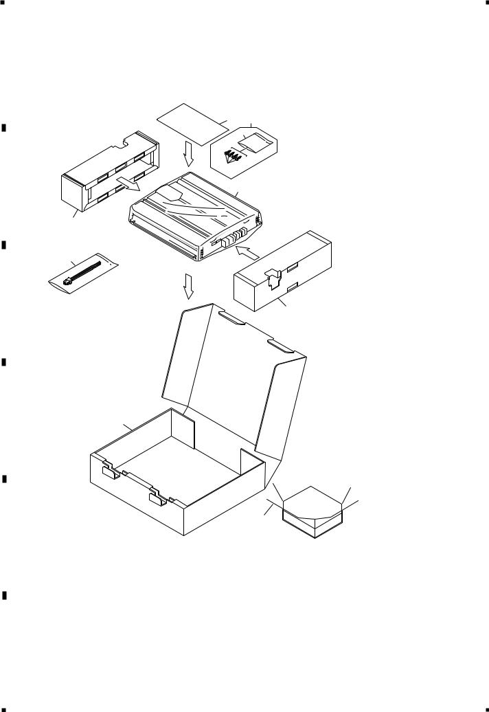
A2. EXPLODED VIEWS AND PARTS LIST
2.1 PACKING
9 1
3
2
B |
6 |
5
4
C
5
D |
7 |
|
8
E
F
6 |
GM-5100T/XU/EW |
1 |
|
2 |
|
3 |
|
4 |
|
|
|
||||
|
|
|

5 |
|
6 |
|
7 |
|
8 |
|
|
|
NOTE:
-Parts marked by “*” are generally unavailable because they are not in our Master Spare Parts List.
-The > mark found on some component parts indicates the importance of the safety factor of the part. Therefore, when replacing, be sure to use parts of identical designation.
-Screws adjacent to mark on the product are used for disassembly.
-For the applying amount of lubricants or glue, follow the instructions in this manual. ( In the case of no amount instructions, apply as you think it appropriate.)
-PACKING SECTION PARTS LIST
|
|
|
|
Part No. |
|
|
Mark No. Description |
GM-5100T/XU/EW |
GM-5100T/XU/UC |
GM-5100T/XU/ES |
GM-5100T/XU/CN |
||
|
1 |
Screw Assy |
CEA4835 |
CEA4835 |
CEA4835 |
CEA4835 |
|
2 |
Screw |
BYC40P180FZK |
BYC40P180FZK |
BYC40P180FZK |
BYC40P180FZK |
* |
3 |
Polyethylene Sheet |
CNM4338 |
CNM4338 |
CNM4338 |
CNM4338 |
|
4 |
Cord Assy |
CDE7736 |
CDE7736 |
CDE7736 |
CDE7736 |
|
5 |
Protector |
CHP2911 |
CHP2911 |
CHP2911 |
CHP2911 |
|
6 |
Polyethylene Bag |
CEG1317 |
CEG1351 |
CEG1317 |
CEG1317 |
|
7 |
Carton |
CHG5360 |
CHG5362 |
CHG5361 |
CHG5465 |
|
8 |
Contain Box |
CHL5360 |
CHL5362 |
CHL5361 |
CHL5465 |
|
9-1 |
Owner’s Manual |
CRD3915 |
CRD3916 |
CRD3918 |
CRB2041 |
|
9-2 |
Polyethylene Bag |
CEG1116 |
CEG1116 |
CEG1116 |
CEG1116 |
* |
9-3 |
Warranty Card |
CRY1157 |
Not used |
Not used |
ARY7046 |
* |
9-4 |
Card |
Not used |
ARY1048 |
Not used |
Not used |
|
9-5 |
Owner’s Manual |
Not used |
Not used |
CRD3919 |
Not used |
* |
9-6 |
Caution Card |
Not used |
Not used |
Not used |
Not used |
|
|
|
|
|
|
|
|
|
|
Part No. |
|
|
|
Mark No. Description |
GM-510T/XU/UC |
|
|
|
||
|
1 |
Screw Assy |
CEA4835 |
|
|
|
|
2 |
Screw |
BYC40P180FZK |
|
|
|
* |
3 |
Polyethylene Sheet |
CNM4338 |
|
|
|
|
4 |
Cord Assy |
CDE7736 |
|
|
|
|
5 |
Protector |
CHP2911 |
|
|
|
|
6 |
Polyethylene Bag |
CEG1351 |
|
|
|
|
7 |
Carton |
CHG5363 |
|
|
|
|
8 |
Contain Box |
CHL5363 |
|
|
|
|
9-1 |
Owner’s Manual |
CRD3917 |
|
|
|
|
9-2 |
Polyethylene Bag |
CEG1116 |
|
|
|
* |
9-3 |
Warranty Card |
Not used |
|
|
|
* |
9-4 |
Card |
ARY1048 |
|
|
|
|
9-5 |
Owner’s Manual |
Not used |
|
|
|
* |
9-6 |
Caution Card |
CRP1324 |
|
|
|
- Owner's Manual
Part No. |
Language |
CRD3915 |
English, Spanish, German, French, Italian, Dutch |
CRD3916 |
English, French, Spanish |
CRD3917 |
English, French, Spanish |
CRD3918 |
English, Spanish |
CRD3919 |
Arabic, Portuguese(B) |
CRB2041 |
Traditional Chinese |
GM-5100T/XU/EW |
7 |
|
|
A
B
C
D
E
F
5 |
|
6 |
|
7 |
|
8 |
|
|
|

1 |
|
2 |
|
3 |
|
4 |
|
|
|
|
2.2 EXTERIOR |
|
|
|
|
43 |
44 |
|
|
|
|
|
|
|
|
|
|
A |
|
|
|
|
7 |
42 |
|
|
|
|
|
|
|
36 |
|
||
|
|
|
|
|
|
|
||
|
6 |
|
|
|
|
|
|
|
|
|
|
|
|
|
|
11 |
|
|
40 |
|
|
|
|
|
|
7 |
|
|
37 |
|
|
|
|
|
|
B |
|
37 |
|
|
|
45 |
|
2 |
|
|
|
|
|
|
|
|
|
|
|
|
|
|
|
|
41 |
|
|
|
12 |
|
|
12 |
|
|
|
|
|
|
12 |
|
|
|
2 |
|
|
|
13 |
|
|
10 |
|
||
|
|
|
|
|
|
|
2 |
|
|
|
|
|
|
|
|
|
|
|
4 |
|
31 |
|
|
|
2 |
|
|
|
|
|
|
|
|
||
|
4 |
|
|
|
|
|
|
|
|
|
|
|
|
|
3 |
|
|
|
|
|
|
32 |
|
|
|
|
C |
|
|
|
|
|
|
|
|
34 |
|
|
|
15 |
|
3 |
|
|
|
33 |
|
|
|
|
|||
|
|
|
|
15 |
|
|
|
|
|
|
|
|
|
15 |
32 |
|
|
|
21 |
33 |
|
|
|
|
||
|
|
|
|
|
14 |
|
||
|
|
|
|
|
|
|
||
|
|
16 |
A |
|
|
|
3 |
|
|
|
20 |
|
|
|
15 |
||
|
|
|
|
|
|
|
|
32 |
|
|
32 |
|
|
|
|
15 |
|
|
|
30 |
|
|
|
|
33 |
|
|
|
15 |
|
|
|
|
|
|
D |
|
29 |
15 |
|
22 |
|
33 |
|
|
|
|
|
18 |
||||
|
|
|
14 |
|
|
|
||
|
|
23 |
|
|
|
|
||
|
|
32 15 |
|
|
|
|
|
|
|
|
24 |
|
|
|
|
|
|
|
|
3 |
25 |
22 |
|
35 |
|
|
|
|
26 |
39 |
|
||||
|
|
|
|
|
|
|
|
|
|
|
|
32 |
|
|
|
|
|
|
|
3 |
27 |
28 |
|
17 |
19 |
|
|
|
|
|
|
|
|||
|
|
2 |
|
4 |
4 |
|
|
|
|
|
2 |
|
|
|
|||
|
|
|
3 |
|
|
|
||
|
|
2 |
|
|
|
|
|
|
E |
|
|
4 |
|
|
|
|
|
|
5 |
|
|
|
|
|
|
|
|
|
|
|
|
|
|
|
|
|
|
2 |
|
|
|
|
|
|
|
|
2 |
|
1 |
|
|
|
|
|
|
|
|
|
|
|
|
|
|
|
9 |
|
|
|
|
1 |
|
|
|
|
|
|
|
|
|
|
|
|
8 |
|
|
|
|
|
|
|
|
1 |
|
|
|
|
1 |
|
|
|
|
|
|
|
|
|
|
F |
|
5 |
|
|
|
|
5 |
|
|
1 |
|
|
|
|
|
||
|
|
|
|
|
|
|
|
|
|
|
5 |
1 |
|
5 |
|
38 |
|
|
|
|
|
|
|
|||
|
|
|
|
|
|
|
|
|
|
8 |
|
GM-5100T/XU/EW |
|
|
|
|
|
1 |
|
2 |
|
3 |
|
4 |
|
|
|
||||
|
|
|

5 |
|
6 |
|
7 |
|
8 |
|
|
|
- EXTERIOR SECTION PARTS LIST
Mark No. Description |
Part No. |
|
Mark No. Description |
Part No. |
||||
|
|
|
|
|
|
|
|
|
|
|
|
|
|
|
|
|
|
|
1 |
Screw |
BBZ30P060FTC |
|
|
26 |
Buss Bar |
CND2470 |
|
2 |
Screw |
BBZ30P080FZK |
|
|
27 |
Buss Bar |
CND2472 |
|
3 |
Screw |
BBZ30P100FZK |
|
|
28 |
Buss Bar |
CND2729 |
|
4 |
Screw |
BBZ30P120FTC |
|
|
29 |
Spacer |
CNM9570 |
|
5 |
Screw |
BSZ30P050FZK |
|
|
30 |
Sub Heat Sink |
CNR1778 |
* |
6 |
Badge |
See Contrast table(2) |
|
|
31 |
Sub Heat Sink |
CNR1779 |
|
7 |
Screw |
CBA1810 |
|
|
32 |
Screw |
IMS30P050FZK |
|
8 |
Case |
CNB3071 |
|
|
33 |
Screw |
PPZ30P100FSN |
|
9 |
Panel |
See Contrast table(2) |
|
|
34 |
Screw |
PPZ30P100FZK |
|
10 |
Panel |
See Contrast table(2) |
|
|
35 |
Terminal(CN850) |
VNF1084 |
|
11 |
Heat Sink |
See Contrast table(2) |
|
|
36 |
Lighting Conductor Unit |
CXC4334 |
|
12 |
Spacer |
CNV8256 |
|
|
37 |
Screw |
IBZ30P060FTC |
|
13 |
Amp Unit |
See Contrast table(2) |
|
|
38 |
Screw |
PPZ30P100FZK |
|
14 |
Screw |
BBZ30P060FZK |
> |
39 Fuse(FU100,101)(30A) |
CEK1330 |
||
|
15 |
Screw |
BBZ30P080FZK |
|
|
40 |
Sheet |
CNM9571 |
|
16 |
Pin Jack(CN111) |
See Contrast table(2) |
|
|
41 |
Screw |
See Contrast table(2) |
|
17 |
Terminal(CN853) |
See Contrast table(2) |
* |
42 |
Seal |
See Contrast table(2) |
|
|
18 |
Terminal(CN855) |
See Contrast table(2) |
|
|
43 |
Holder |
See Contrast table(2) |
|
19 |
Terminal(CN856) |
See Contrast table(2) |
|
|
44 |
Nut |
See Contrast table(2) |
|
20 |
Socket(CN801) |
CKM1463 |
|
|
45 |
Washer |
See Contrast table(2) |
|
21 |
Holder |
CND2456 |
|
|
|
|
|
|
22 |
Terminal |
CND2458 |
|
|
|
|
|
|
23 |
Buss Bar |
CND2467 |
|
|
|
|
|
|
24 |
Buss Bar |
CND2468 |
|
|
|
|
|
|
25 |
Buss Bar |
CND2469 |
|
|
|
|
|
|
|
|
|
|
|
|
|
|
A
B
C
D
E
F
GM-5100T/XU/EW |
9 |
|
|
5 |
|
6 |
|
7 |
|
8 |
|
|
|
 Loading...