


Service
Manual 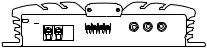
ORDER NO.
CRT2168
BRIDGEABLE FOUR-CHANNEL POWER AMPLIFIER
GM-X424 X1R/UC, ES, EW
GM-X324 X1R/UC
CONTENTS
1. |
SAFETY INFORMATION ............................................ |
1 |
5. |
ELECTRICAL PARTS LIST ........................................ |
12 |
2. |
EXPLODED VIEWS AND PARTS LIST ....................... |
2 |
6. ADJUSTMENT.......................................................... |
16 |
|
3. |
SCHEMATIC DIAGRAM ............................................. |
6 |
7. GENERAL INFORMATION ....................................... |
16 |
|
4. |
PCB CONNECTION DIAGRAM .................................. |
8 |
|
7.1 DISASSEMBLY ................................................... |
16 |
|
|
|
8. |
OPERATIONS AND SPECIFICATIONS..................... |
17 |
1. SAFETY INFORMATION
This service manual is intended for qualified service technicians; it is not meant for the casual do-it-yourselfer. Qualified technicians have the necessary test equipment and tools, and have been trained to properly and safely repair complex products such as those covered by this manual.
Improperly performed repairs can adversely affect the safety and reliability of the product and may void the warranty. If you are not qualified to perform the repair of this product properly and safely, you should mot risk trying to do so and refer the repair to a qualified service technician.
UC model
CAUTION
This service manual is intended for qualified service technicians; it is not meant for the casual do-it-yourselfer. Qualified technicians have the necessary test equipment and tools, and have been trained to properly and safely repair complex products such as those covered by this manual.
Improperly performed repairs can adversely affect the safety and reliability of the product and may void the warranty. If you are not qualified to perform the repair of this product properly and safely; you should not risk trying to do so and refer the repair to a qualified service technician.
WARNING
Lead in solder used in this product is listed by the California Health and Welfare agency as a known reproductive toxicant which may cause birth defects or other reproductive harm (California Health & Safety Code, Section 25249.5). When servicing or handling circuit boards and other components which contain lead in solder, avoid unprotected skin contact with the solder. Also, when soldering do not inhale any smoke or fumes produced.
PIONEER ELECTRONIC CORPORATION 4-1, Meguro 1-Chome, Meguro-ku, Tokyo 153-8654, Japan PIONEER ELECTRONICS SERVICE INC. P.O.Box 1760, Long Beach, CA 90801-1760 U.S.A.
PIONEER ELECTRONIC [EUROPE] N.V. Haven 1087 Keetberglaan 1, 9120 Melsele, Belgium
PIONEER ELECTRONICS ASIACENTRE, PTE.LTD. 501 Orchard Road, #10-00, Wheelock Place, Singapore 238880
C PIONEER ELECTRONIC CORPORATION 1998
K-ZEU. JAN. 1998 Printed in Japan
GM-X424, GM-X324
2. EXPLODED VIEWS AND PARTS LIST
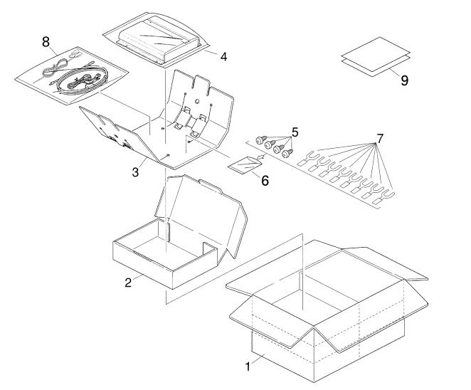
2.1 PACKING
Fig. 1
NOTE:
-Parts marked by “*”are generally unavailable because they are not in our Master Spare Parts List.
-Screws adjacent to mark on the product are used for disassembly.
(1) PACKING SECTION PARTS LIST
Mark No. |
Description |
Part No. |
Mark No. |
Description |
Part No. |
||
1 |
Contain Box |
See Contrast table (2) |
|
|
6 |
Polyethylene Bag |
HEG0011 |
2 |
Carton |
See Contrast table (2) |
|
|
7 |
Terminal(x8) |
See Contrast table (2) |
3 |
Protector |
HHP0020 |
|
|
8 |
Cord Assy |
See Contrast table (2) |
4 |
Polyethylene Bag |
HEG0009 |
|
|
9-1 |
Owner’s Manual |
See Contrast table (2) |
5 |
Screw(x4) |
BYC40P180FZK |
|
|
9-2 |
Owner’s Manual |
See Contrast table (2) |
|
|
|
* |
9-3 |
Warranty Card |
See Contrast table (2) |
|
|
|
|
* |
9-4 |
Caution Card |
See Contrast table (2) |
|
|
|
|
* |
9-5 |
Card |
See Contrast table (2) |
|
2
GM-X424, GM-X324
(2) CONTRAST TABLE
GM-X424/X1R/UC, GM-X424/X1R/ES, GM-X424/X1R/EW and GM-X324/X1R/UC are constructed the same except for the following:
|
|
|
|
|
Part No. |
|
|
|
|
|
|
GM-X424 |
|
|
GM-X324 |
Mark |
No. |
Symbol and Description |
X1R/UC |
X1R/ES |
|
X1R/EW |
X1R/UC |
|
1 |
Contain Box |
HHL0142 |
HHL0143 |
|
HHL0144 |
HHL0141 |
|
2 |
Carton |
HHG0142 |
HHG0143 |
|
HHG0144 |
HHG0141 |
|
7 |
Terminal(x8) |
HKC0001 |
HKC0003 |
|
HKC0003 |
HKC0003 |
|
8 |
Cord Assy |
Not used |
HDE4419 |
|
HDE4419 |
Not used |
|
9-1 |
Owner’s Manual |
HRD0052 |
HRD0050 |
|
HRD0055 |
HRD0054 |
|
9-2 |
Owner’s Manual |
Not used |
HRD0053 |
|
Not used |
Not used |
* |
9-3 |
Warranty Card |
HRY1070 |
Not used |
|
HRY1087 |
Not used |
* |
9-4 |
Caution Card |
HRP0006 |
Not used |
|
Not used |
Not used |
* |
9-5 |
Card |
Not used |
Not used |
|
Not used |
ARY1048 |
- Owner's Manual
Model |
Part No. |
Language |
|
|
|
GM-X424/X1R/UC |
HRD0052 |
English, French |
|
|
|
GM-X424/X1R/ES |
HRD0050 |
English, Spanish |
|
|
|
|
HRD0053 |
Arabic, Portuguese(B) |
|
|
|
GM-X424/X1R/EW |
HRD0055 |
English, French, German, Dutch, Spanish, Italian |
|
|
|
GM-X324/X1R/UC |
HRD0054 |
English, French |
|
|
|
3
GM-X424, GM-X324
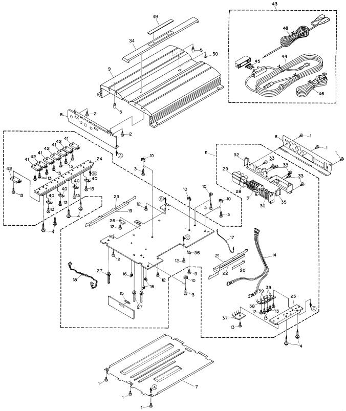
2.2 EXTERIOR
Fig. 2
4
GM-X424, GM-X324
(1) EXTERIOR SECTION PARTS LIST
Mark No. |
Description |
Part No. |
Mark No. |
Description |
Part No. |
|
1 |
Screw |
BSZ30P050FZK |
|
26 |
Clamper |
HNV0003 |
2 |
Screw(M3x6) |
CBA1320 |
27 |
Holder |
HNV0005 |
|
3 |
Screw(M3x12) |
CBA1323 |
28 |
Pin Jack(CN852) |
See Contrast table (2) |
|
4 |
Screw |
CBA1382 |
29 |
Pin Jack(CN851) |
See Contrast table (2) |
|
5 |
Screw |
HBA0006 |
30 |
Terminal(CN601) |
See Contrast table (2) |
|
6 |
Panel |
See Contrast table (2) |
31 |
Terminal(CN303) |
See Contrast table (2) |
|
7 |
Case |
HNB0015 |
32 |
Holder |
HNC0006 |
|
8 |
Panel |
See Contrast table (2) |
33 |
Screw |
PPZ30P060FZK |
|
9 |
Heat Sink |
See Contrast table (2) |
34 |
Plate Unit |
See Contrast table (2) |
|
10 |
Spacer |
HNV3975 |
35 |
Fuse(FU999)(25A) |
HEK0025 |
|
11 |
Amp Unit |
See Contrast table (2) |
36 |
Holder |
CNC5399 |
|
12 |
Screw |
BMS30P060FZK |
37 |
Diode(D609) |
RBV-602L |
|
13 |
Screw |
BMS30P080FMC |
38 |
Thermistor(TH603) |
CCX1013 |
|
14 |
Connector(CN854) |
HDE5212 |
39 |
FET(Q610-613) |
IRFIZ44N |
|
15 |
Plug(CN863) |
CKS1618 |
40 |
Transistor(Q313-316) |
2SD2343 |
|
16 |
Clamper |
HNV0006 |
41 |
Transistor(Q329-332) |
2SB1587 |
|
17 |
Cord(CN901) |
HDC1030 |
42 |
Transistor(Q325-328) |
2SD2438 |
|
18 |
Cord(CN602) |
HDE4610 |
43 |
Cord Assy |
See Contrast table (2) |
|
19 |
Bass Bar |
HNC0014 |
44 |
Special Red Battery Wire |
See Contrast table (2) |
|
20 |
Holder |
HNC5538 |
45 |
Fuse(30A) |
See Contrast table (2) |
|
21 |
Holder |
HNC5540 |
46 |
Ground Wire(Black) |
See Contrast table (2) |
|
22 |
Holder |
HNC5541 |
47 |
••••• |
|
|
23 |
Holder |
HNC5841 |
48 |
System Remote Control |
See Contrast table (2) |
|
24 |
Heat Sink(Sub Heat Sink) HNR0050 |
49 |
Badge Unit |
See Contrast table (2) |
||
25 |
Heat Sink(Sub Heat Sink) HNR0052 |
50 |
Light Pipe Unit |
HXA0182 |
||
(2) CONTRAST TABLE
GM-X424/X1R/UC, GM-X424/X1R/ES, GM-X424/X1R/EW and GM-X324/X1R/UC are constructed the same except for the following:
|
|
|
|
Part No. |
|
|
|
|
|
GM-X424 |
|
|
GM-X324 |
Mark No. |
Symbol and Description |
X1R/UC |
X1R/ES |
|
X1R/EW |
X1R/UC |
6 |
Panel |
HNB0053 |
HNB0071 |
|
HNB0071 |
HNB0054 |
8 |
Panel |
HNB0048 |
HNB0070 |
|
HNB0070 |
HNB0049 |
9 |
Heat Sink |
HNR0091 |
HNR0098 |
|
HNR0098 |
HNR0095 |
11 |
Amp Unit |
HWH0054 |
HWH0052 |
|
HWH0051 |
HWH0053 |
28 |
Pin Jack(CN852) |
HKB0002 |
HKB0001 |
|
HKB0001 |
Not used |
29 |
Pin Jack(CN851) |
HKB0004 |
HKB0003 |
|
HKB0003 |
HKB0003 |
30 |
Terminal(CN601) |
HKE0002 |
HKE0001 |
|
HKE0001 |
HKE0001 |
31 |
Terminal(CN303) |
HKE0006 |
HKE0005 |
|
HKE0005 |
HKE0005 |
34 |
Plate Unit |
HXA0165 |
HXA0162 |
|
HXA0162 |
HXA0162 |
43 |
Cord Assy |
Not used |
HDE4419 |
|
HDE4419 |
Not used |
44 |
Special Red Battery Wire |
Not used |
HDE4423 |
|
HDE4423 |
Not used |
45 |
Fuse(30A) |
Not used |
HEK0030 |
|
HEK0030 |
Not used |
46 |
Ground Wire(Black) |
Not used |
HDE4455 |
|
HDE4455 |
Not used |
48 |
System Remote Control |
Not used |
HDE0007 |
|
HDE0007 |
Not used |
49 |
Badge Unit |
HXA0168 |
HXA0164 |
|
HXA0164 |
HXA0164 |
5
1 |
|
2 |
|
3 |
|
4 |
|
|
|
GM-X424, GM-X324
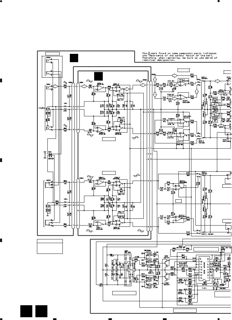
3. SCHEMATIC DIAGRAM
Note: When ordering service parts, be sure to refer to "EXPLODED VIEWS AND PARTS LIST" or "ELECTRICAL PARTS
A
LIST".
THRU-PUT |
A MOTHER PCB |
|
GM-X424 only |
||
B ISOLATOR PCB |
||
A Lch |
||
|
LPF / HPF |
R179, 180 : GM-X324 only |
BASS |
|
VR153 : GM-X424 only |
|
|
|
B
A Rch
ISOLATOR
ISOLATOR
B Lch
C
B Rch
AMP UNIT
Consists of
MOTHER PCB
ISOLATOR PCB
SIGNAL ROUTE
 : AUDIO SIGNAL
D
FLAT A
HPF
FLAT A
SWITCHING CONTROL
6 A B
DC-DC CONVERTER |
OVER VOLTA |
|
DETECTOR |
S601, R641 : ES and EW
models only
THERMO-DETECTOR
1 |
2 |
3 |
4 |

5
BASS BOOST
BUFFER AMP
4R7/50
4R7/50
FLAT AMP
MUTE
MUTE
FLAT AMP
POWER CONTROL / MUTE
22/50
R VOLTAGE
TETECTOR
6 |
|
7 |
|
8 |
|
|
GM-X424, GM-X324
A
PRE DRIVER |
POWER AMP |
OVER CURRENT
DETECTOR
OVER VOLTAGE
DETECTOR
B
POWER |
C |
DETECTOR |
OVER
CURRENT PROTECTOR
&
OVER
VOLTAGE PROTECTOR
ES and EW models only
GROUND WIRE |
D |
BATTERY WIRE
SYSTEM REMOTE
CONTROL
Fig. 3
A 7
5 |
|
6 |
|
7 |
|
8 |
|
|
|
 Loading...