


Service
Manual
 LX470
LX470
ORDER NO.
CRT2498
AUDIO SYSTEM POWER AMPLIFIER
VEHICLE |
DESTINATION |
PRODUCED AFTER |
TOYOTA PART No. |
ID No. |
PIONEER MODEL No. |
||
LEXUS LX470 |
U.S.A |
August 2000 |
86280-60250 |
|
|
|
GM-8406ZT/UC |
|
|
|
|||||
|
|
|
|
|
|
|
|
|
Canada |
|
|
|
|
|
GM-8406ZT-91/UC |
|
|
|
|
|
|
||
|
|
|
|
|
|
|
|
Manufactured for TOYOTA |
|
by PIONEER CORPORATION |
PUB. NO. CRT2498 |

GM-8406ZT,8406ZT-91
NOTE:
-The GM-8406ZT-91/UC is supplementally genuine part for a TOYOTA vehicle, and a Pioneer product for recycling stock.
-As for the structure and electrical system, there is no difference between the GM-8406ZT-91/UC and GM-8406ZT/UC.
-Supplementally model is identical to the original except for the addition of following items.
|
*:Non spare part |
|
Part No. |
|
|
Description |
GM-8406ZT-91/UC |
|
|
Cover |
CEG1057 |
Protector |
CHP2329 |
Protector |
CHP2330 |
Carton |
CHG4144 |
Contain Box |
CHL4145 |
|
|
- When diagnosing a product, take care of its heated portion.
Power IC |
(IC801,802,803) |
Power Supply IC (IC901,902) |
|
DSP IC |
(IC201,251) |
Heat Sink |
|
IC Holder |
|
CONTENTS
1. |
SAFETY INFORMATION............................................ |
2 |
7. |
GENERAL INFORMATION....................................... |
28 |
2. |
EXPLODED VIEWS AND PARTS LIST ...................... |
3 |
|
7.1 DIAGNOSIS ....................................................... |
28 |
3. |
BLOCK DIAGRAM AND SCHEMATIC DIAGRAM .... |
5 |
|
7.1.1 DISASSEMBLY......................................... |
28 |
4. |
PCB CONNECTION DIAGRAM................................ |
12 |
|
7.1.2 CONNECTOR FUNCTION DESCRIPTION ...... |
30 |
5. |
ELECTRICAL PARTS LIST........................................ |
20 |
|
7.2 IC ........................................................................ |
31 |
6. |
ADJUSTMENT ......................................................... |
24 |
|
7.3 EXPLANATION................................................... |
34 |
|
|
|
|
7.3.1 OPERATIONAL FLOW CHART ................. |
34 |
|
|
|
|
7.3.2 SYSTEM BLOCK DIAGRAM..................... |
36 |
|
|
|
8. |
SPECIFICATIONS ..................................................... |
37 |
1. SAFETY INFORMATION
This service manual is intended for qualified service technicians; it is not meant for the casual do-it-yourselfer. Qualified technicians have the necessary test equipment and tools, and have been trained to properly and safely repair complex products such as those covered by this manual.
Improperly performed repairs can adversely affect the safety and reliability of the product and may void the warranty. If you are not qualified to perform the repair of this product properly and safely; you should not risk trying to do so and refer the repair to a qualified service technician.
2
GM-8406ZT,8406ZT-91
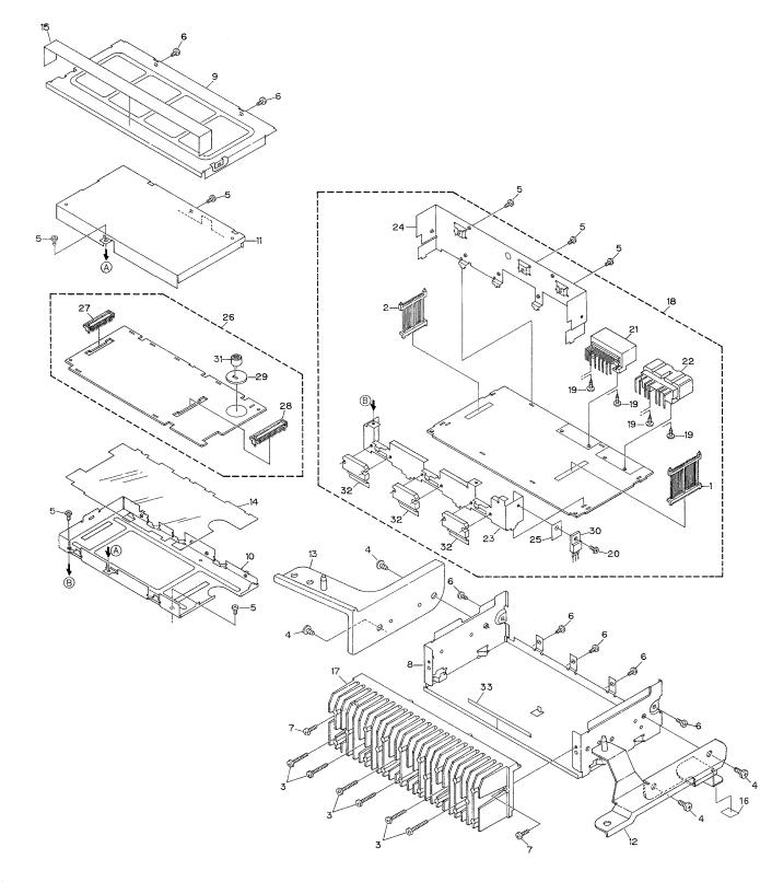
2. EXPLODED VIEWS AND PARTS LIST
2.1 EXTERIOR
3
GM-8406ZT,8406ZT-91
NOTE:
-Parts marked by “*”are generally unavailable because they are not in our Master Spare Parts List.
-Screws adjacent to mark on the product are used for disassembly.
-EXTERIOR SECTION PARTS LIST
Mark No. Description |
Part No. |
|
Mark No. Description |
Part No. |
||
|
|
|
|
|
|
|
1 |
Plug(CN906) |
CKS4240 |
16 |
Cushion |
CNM7009 |
|
2 |
Plug(CN905) |
CKS4242 |
17 |
Heat Sink |
CNR1566 |
|
3 |
Screw |
BMZ30P200FMC |
18 |
Amp Unit |
CWM7110 |
|
4 |
Screw |
BMZ50P060FMC |
19 |
Screw |
BPZ30P060FSN |
|
5 |
Screw |
BSZ26P060FMC |
20 |
Screw |
BSZ26P060FMC |
|
6 |
Screw |
BSZ30P060FMC |
21 |
Connector(CN902) |
CKM1308 |
|
7 |
Screw |
BSZ30P100FMC |
22 |
Connector(CN901) |
CKM1310 |
|
8 |
Chassis |
CNA2142 |
23 |
Holder |
CNC8187 |
|
9 |
Case |
CNB2563 |
24 |
Bracket |
CNC8681 |
|
10 |
Shield Case |
CNC8185 |
25 |
Sheet |
CNM7015 |
|
11 |
Shield Case |
CNC8186 |
26 |
DSP Unit |
CWM7111 |
|
12 |
Bracket |
CNC8920 |
27 |
Socket(CN102) |
CKS3632 |
|
13 |
Bracket |
CNC8919 |
28 |
Socket(CN101) |
CKS4241 |
|
14 |
Insulator |
CNM6145 |
29 |
Spacer |
CNV6284 |
|
15 |
Seal |
CNM6686 |
30 |
IC(IC902) |
BA178M05T |
|
|
|
|
31 |
Microphone(MIC401) |
CPM1011 |
|
|
|
|
32 |
IC(IC801,802,803) |
PAL006A |
|
|
|
|
33 |
Seal |
CNM7170 |
|
4
1 |
|
2 |
|
3 |
|
4 |
|
|
|
GM-8406ZT,8406ZT-91
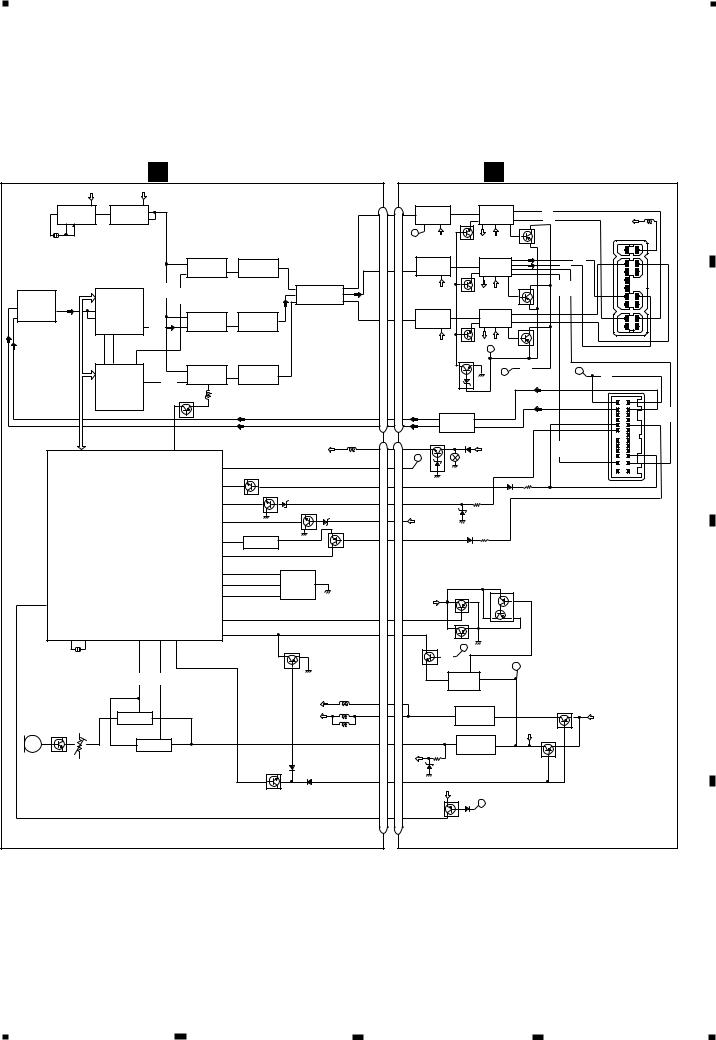
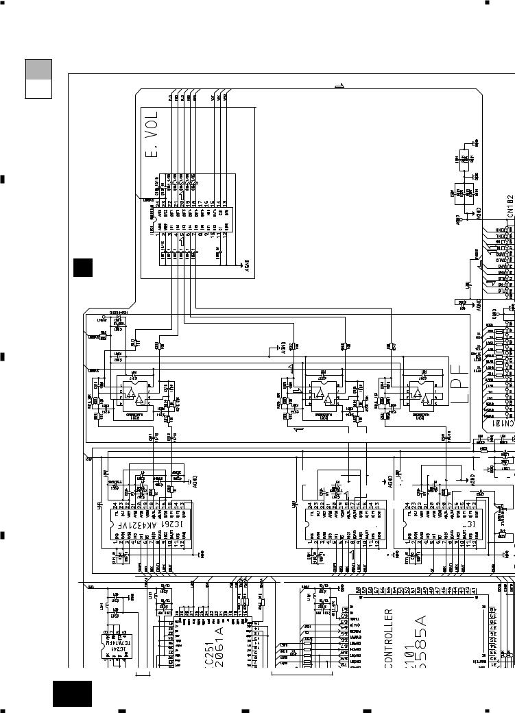
3. BLOCK DIAGRAM AND SCHEMATIC DIAGRAM
3.1 BLOCK DIAGRAM
A
|
|
|
|
|
|
|
A DSP UNIT |
|
|
|
|
|
|
|
|
|
|
|
|
|
|
|
B AMP UNIT |
|
|
|
|
|
|||||||||
|
CRYSTAL |
VCC |
|
VCC |
|
|
|
|
|
|
|
|
|
|
|
|
CN102 |
CN905 |
|
|
|
|
|
|
|
|
|
|
|
|
|
|
|||||
|
|
|
|
|
|
|
|
|
|
|
|
|
|
|
|
|
|
|
|
|
FRONT-L |
|
|
FRONT |
|
|
|
|
|
|
|
||||||
|
OSCILLATOR |
|
|
|
|
|
|
|
|
|
|
|
|
|
|
|
|
|
|
|
|
|
|
|
|
|
|
|
|
|
|||||||
|
8 |
|
8 |
|
|
|
|
|
|
|
|
|
|
|
|
|
|
|
|
|
OPE AMP |
|
POWER AMP |
|
|
|
|
|
|
||||||||
|
1 |
IC231 |
2 |
1 |
IC241 |
D |
2 |
|
|
|
|
|
|
|
|
|
|
|
|
FLO |
|
|
FLIN |
IC701 |
|
11 |
IC801 |
9 |
(FLP) |
|
|
|
|
|
|||
|
|
|
|
|
|
|
|
|
|
|
|
|
|
|
|
|
|
|
|
|
|
||||||||||||||||
|
TC7WU04F |
CK |
TC7W74FU |
|
3 |
|
|
|
|
|
|
|
|
|
|
|
|
|
13 |
13 |
3 NJM2068MD 1 |
10 |
PAL006A |
7 |
|
|
|
|
L901 |
|
|||||||
|
|
q |
|
|
|
|
|
|
|
|
|
|
|
|
|
(FLM) |
|
|
|
BU1 |
|
||||||||||||||||
|
|
|
|
|
|
|
|
|
|
|
|
|
|
|
|
|
|
|
|
|
|
|
|
|
|
|
|
|
|
|
|
|
|
|
|||
|
7 |
3 |
|
|
|
|
|
|
|
|
|
|
|
|
|
|
|
|
|
|
|
|
PEE |
2 |
6 |
|
|
4 |
22 |
25 |
Q801 |
|
|
|
|
|
|
|
|
|
|
|
|
|
|
|
|
|
|
|
|
|
|
|
|
|
|
|
|
|
P |
|
SYS4 |
|
STBY1 MPUT |
|
|
|
|
|
|
CN901 |
|
||
|
|
|
|
|
|
|
|
|
|
|
|
|
|
|
|
|
|
|
|
|
|
|
|
|
Q831 |
|
|
|
|
|
|
|
|||||
|
|
|
|
|
|
|
|
|
|
|
|
|
|
|
|
|
|
|
|
|
|
|
REAR-L |
|
|
REAR |
|
|
|
|
|
|
B.U |
|
|||
|
|
|
|
|
|
|
|
|
|
|
FRONT DAC |
|
|
FRONT LPF |
|
|
|
|
|
|
|
OPE AMP |
|
POWER AMP |
7 |
|
|
(RLM) |
|
|
|
||||||
|
|
|
|
|
|
|
|
|
|
5 XTI |
|
|
|
|
|
|
|
|
|
|
|
|
|
|
|
|
|
|
|
|
|
WFL- |
WFL+ |
|
|||
|
|
|
|
|
|
|
|
|
|
IC261 |
|
|
IC311 |
1 |
|
|
|
RLO 11 |
|
|
IC702 |
|
|
11 |
IC802 |
|
9 |
(RLP) |
|
|
|||||||
|
|
|
|
|
|
|
|
|
|
8 |
AK4321VF |
|
2 |
NJM2068MD |
|
|
ELECTRONIC |
11 |
RLIN NJM2068MD 1 |
|
10 |
PAL006A |
1719 |
|
|
|
|
|
|
||||||||
|
|
|
|
|
|
|
|
|
|
|
SDATA |
AOUTL 18 |
|
|
|
|
|
|
|
3 |
|
6 |
|
|
4 |
22 |
25 |
|
|
|
|
|
|
|
|||
|
|
|
|
|
|
|
|
|
|
|
|
|
|
|
|
|
|
VOLUME |
|
|
|
|
|
|
|
|
|
(TWLM) |
(TWLP) |
|
|
|
|
||||
A/D |
|
|
|
|
|
|
|
(256FS) |
|
|
|
|
|
|
|
3 |
|
|
22 |
|
|
|
|
|
|
|
|
|
|
Q802 |
|
|
|
|
|||
|
|
|
|
|
|
|
(FDATA) |
|
|
|
|
|
|
IN1 |
IC351 |
OUT1 |
|
|
|
|
SYS4 |
|
STBY1 MPUT |
|
|
|
|
|
|||||||||
IC181 |
|
|
|
DSP |
|
|
|
|
|
|
|
|
|
|
20 |
|
|
|
|
|
|
|
|
|
RL+ |
|
|||||||||||
|
|
|
|
|
|
|
|
|
|
|
5 IN3 |
OUT3 |
|
|
|
|
|
|
Q832 |
|
|
|
|
RL- |
|
||||||||||||
AK5351VF |
|
|
|
|
|
|
|
|
|
|
|
|
7 IN5 |
PM0017AMOUT5 18 |
|
|
SUB WOOFER |
|
SUB WOOFER |
|
|
|
|
|
|||||||||||||
7 AINL- |
21 |
|
SDI1 |
|
IC201 |
|
|
|
|
|
REAR DAC |
|
|
REAR LPF |
|
|
|
|
|
|
|
OPE AMP |
|
POWER AMP |
7 |
|
|
|
|
|
|
||||||
SDATA |
|
PD2061A |
|
|
|
|
|
|
|
|
|
|
|
|
|
|
|
|
|
|
|
|
|
|
|
|
|
|
|
|
|||||||
6 AINL+ |
|
|
19 SDI0 |
|
|
|
|
|
|
5 XTI |
IC281 |
|
|
IC331 |
1 |
|
|
|
WFO |
9 |
9 |
WFIN |
IC703 |
|
|
11 |
IC803 |
|
9 |
|
|
|
FL- |
FL+ |
|
||
|
|
|
SDO0 |
SDO2 |
|
|
|
|
|
|
AK4321VF |
|
2 |
|
|
|
|
|
2 NJM2068MD 1 |
10 |
PAL006A |
|
|
|
|
|
|
||||||||||
|
|
|
SDO1 16 (RDATA) |
|
8 |
SDATA |
AOUTL 18 |
|
NJM2068MD |
|
|
|
|
|
|
|
|
|
6 |
|
|
4 |
22 |
25 |
Q803 |
|
|
|
|
|
|
||||||
|
|
|
17 |
16 |
|
|
|
|
|
|
|
|
|
|
|
|
|
|
|
|
|
|
|
|
SYS4 |
|
STBY1 MPUT |
|
|
|
|
|
|
|
|
||
|
|
|
|
|
|
|
|
|
|
|
|
|
|
|
|
|
|
|
|
|
|
|
|
|
Q833 |
|
|
|
|
|
|
|
|
||||
|
|
|
|
|
|
|
|
|
|
|
|
|
|
|
|
|
|
|
|
|
|
|
|
|
|
|
|
|
A |
|
|
|
|
|
|
OUTPUT |
|
|
|
|
19 |
18 |
16 |
|
|
|
|
|
|
|
|
|
|
|
|
|
|
|
|
|
|
|
|
|
Q950 |
|
|
|
|
|
|
|
|
CONNECTOR |
|
|
|
|
|
|
|
|
|
WOOFER DAC |
|
WOOFER LPF |
|
|
|
|
|
|
|
|
|
|
|
|
|
|
|
|
|
|
|
|
|
||||||
|
|
|
|
|
|
|
|
|
|
|
|
|
|
|
|
|
|
|
|
|
|
|
|
|
|
|
|
|
|
|
|||||||
|
|
|
SDI0 |
SDI1 |
SDO1 |
|
|
|
|
5 XTI |
IC291 |
|
|
IC341 |
7 |
|
|
|
|
|
|
|
|
|
|
|
|
|
B |
(FSW) |
|
|
C |
|
|
|
|
|
|
|
|
|
|
|
|
|
|
|
|
|
|
|
|
|
|
|
|
|
|
|
|
|
|
|
|
||||||||||
|
|
|
|
|
|
|
|
AK4321VF |
|
5 |
|
|
|
|
|
|
|
|
|
|
|
|
|
|
|
|
|
|
(SPD) |
|
|
||||||
|
|
|
DSP |
SDO2 |
15 |
(WDATA) |
8 SDATA |
AOUTR AOUTL 18 |
|
NJM2068MD |
|
|
|
|
|
|
|
|
|
|
|
|
|
|
|
|
|
|
|
|
INPUT |
|
|||||
|
|
|
|
|
|
|
|
|
|
17 |
|
|
|
|
|
|
|
|
|
|
|
|
|
|
|
|
|
|
|
|
|
|
CONNECTOR |
B |
|||
|
|
|
|
IC251 |
|
|
|
|
|
|
|
|
|
|
|
|
|
|
|
|
|
|
|
|
|
|
|
|
|
|
|
|
|||||
|
|
|
|
|
|
|
|
|
|
|
|
|
|
|
|
|
|
|
|
|
|
|
|
|
|
|
|
|
|
|
|
|
|
|
|||
|
|
|
|
PD2061A |
|
|
|
|
Q291 |
|
|
|
|
|
|
|
|
|
|
|
|
|
|
|
|
|
|
|
|
|
|
|
SPDO |
SPD |
|
||
|
|
|
|
|
|
|
|
|
|
|
|
|
|
|
|
|
|
|
|
|
|
|
AUDIO INPUT |
|
|
|
|
|
|
|
|||||||
|
|
|
|
|
|
|
|
|
|
|
|
|
|
|
|
|
|
|
|
|
|
|
|
|
|
|
|
|
|
|
L- |
L+ |
(TWLP) |
||||
|
|
|
|
|
|
|
|
|
|
|
|
|
|
|
|
|
|
|
|
|
|
|
|
|
|
BUFFER |
2 |
|
|
|
|
|
|
|
|
||
|
|
|
|
|
|
|
|
|
|
|
|
|
|
|
|
|
|
|
|
|
5 |
5 |
|
|
1 |
IC501 |
|
|
|
|
|
|
MUTE |
|
|||
|
|
|
|
|
|
|
|
|
|
|
|
|
|
|
|
|
|
|
|
|
|
|
|
|
|
|
|
|
|
N-MU |
|||||||
|
|
|
|
|
|
|
|
|
|
|
|
|
|
|
|
|
|
|
|
|
|
|
|
|
7 |
6 |
|
|
|
|
|
(H/U MUT) |
|
||||
|
|
|
|
|
|
|
|
|
|
|
|
|
|
|
|
|
|
|
|
|
6 |
6 |
|
|
NJM2068MD |
|
|
|
|
|
|
|
|
|
|||
|
|
|
|
|
|
|
|
|
|
|
|
|
|
|
|
|
|
|
|
|
|
|
5V REGULATOR |
|
|
|
|
|
|
|
ACC |
|
|
||||
|
|
|
|
|
|
|
|
|
|
|
|
|
|
|
|
|
|
|
|
|
|
|
|
|
|
|
|
|
|
|
|
|
|||||
|
|
|
|
|
|
|
|
68 |
|
|
|
|
|
|
|
|
VDD |
|
VDD5 |
3 |
16 VDD5 |
|
Q903 |
|
BU1 |
|
|
(TWLM) |
|
CN902 |
|
|
|||||
|
|
|
|
|
|
|
|
|
|
|
|
|
|
|
|
|
|
|
|
|
|
|
|
|
|
TMUT |
|
||||||||||
|
|
|
|
|
|
|
|
|
DSPERR |
|
|
|
|
|
|
|
|
|
|
|
|
|
PEE P |
|
|
|
Q915 |
|
|
|
|
|
|
|
|
||
|
|
|
|
|
|
|
|
|
|
|
|
|
|
|
|
|
|
|
|
|
|
|
|
|
|
|
|
|
|
|
FL- |
FL+ |
|
||||
|
|
|
|
|
|
|
|
|
|
|
|
21 |
|
|
|
|
|
|
PEE |
|
|
|
|
|
|
|
|
|
|
|
|
|
|
||||
|
|
|
|
|
|
|
|
|
|
|
PEE |
SYSTEM MUTE |
|
|
|
|
11 |
8 |
|
|
|
|
|
|
|
|
|
|
|
|
|
|
|||||
|
|
|
|
|
|
|
|
|
|
|
|
|
|
|
|
|
|
|
|
|
|
|
|
|
|
|
|
|
|
|
|
|
|
|
|
||
|
|
|
|
|
|
|
|
|
|
|
|
|
|
|
Q175 |
|
|
|
|
|
|
|
|
|
|
|
|
|
|
|
|
|
|
|
|
|
|
|
|
|
|
|
|
|
|
|
|
|
|
SMUTEIN |
31 |
|
|
|
|
|
|
MUTI |
13 |
6 |
MUTIN |
|
|
|
|
|
|
|
|
|
|
|
|
|
|
|
|
|
|
|
|
|
|
|
|
|
|
|
|
ACC SENSE |
|
|
|
|
|
|
|
|
|
|
|
|
|
|
|
|
|
||||||
|
|
|
|
|
|
|
|
|
|
|
|
|
|
|
|
|
|
|
|
|
|
|
|
|
|
|
|
|
|
|
|
|
|
|
|
||
|
|
|
|
|
|
|
|
|
|
|
|
|
|
|
Q155 |
|
|
|
|
|
|
|
|
|
|
|
|
|
|
|
|
|
|
|
|
|
|
|
|
|
|
|
|
|
|
|
|
|
|
ASENS 17 |
|
|
BACK UP SENSE |
|
ACC1 |
6 |
13 |
ACC1 |
|
|
|
|
|
|
|
|
|
|
|
|
|
|
|||
|
|
|
|
|
|
|
|
|
|
|
|
|
|
|
|
|
Q151 |
|
|
|
|
BU1 |
|
|
|
|
|
|
|
|
|
|
|
|
|
|
|
|
|
|
|
|
|
|
|
|
|
|
|
|
16 |
|
|
|
|
|
|
BU1 |
7 |
12 |
|
|
|
|
|
|
|
|
|
|
|
|
|
|
|
|
|
|
|
|
IC101 |
|
|
|
|
|
BSENS |
|
|
|
|
|
|
|
|
|
|
|
|
|
|
|
|
|
|
|
|
|
|||||
|
|
|
|
|
|
|
|
|
|
|
|
|
|
|
|
|
|
|
|
|
|
|
|
|
|
|
|
|
|
|
|
|
|||||
|
|
|
|
|
|
|
|
|
|
|
|
|
|
|
|
Q171 |
|
|
|
|
|
|
|
|
|
|
|
|
|
|
|
|
|||||
|
|
|
|
|
PD5585A |
|
|
|
|
|
|
|
RESET |
|
|
|
|
|
|
|
|
|
|
|
|
|
|
|
|
|
|
|
|
||||
|
|
|
|
|
|
|
|
|
|
9 |
1 |
2 |
|
|
|
NMUT1 |
12 |
7 |
NMUT |
|
|
|
|
|
|
|
|
|
|
|
|
|
|
||||
|
|
|
|
|
|
|
|
|
|
|
|
RESET |
IC131 |
NAVI/MUTE |
|
|
|
|
|
|
|
|
|
|
|
|
|
|
|
||||||||
|
|
|
|
|
|
|
|
|
|
|
|
|
|
S-80730ANDT |
|
|
|
|
|
|
|
|
|
|
|
|
|
|
|
|
|
|
|
|
|||
|
|
|
|
|
|
|
|
|
|
|
NAVIMUTE 79 |
|
|
|
|
|
|
|
|
|
|
|
|
|
|
|
|
|
|
|
|
|
|
|
|
||
|
|
|
|
|
|
|
|
|
|
|
|
|
22 |
|
2 |
BUS DRIVER |
|
|
|
|
|
|
|
|
|
|
|
|
|
|
|
|
|
|
|
||
|
|
|
SYSTEM CONTROLLER |
|
|
AVCIN |
|
|
|
|
|
|
15 |
4 |
|
|
|
|
|
|
|
|
|
|
|
|
|
|
|
||||||||
|
|
|
|
|
|
23 |
|
1 |
IC141 |
7 |
|
|
|
|
|
|
|
|
|
|
|
|
|
|
|
|
|
||||||||||
|
|
|
|
|
|
|
|
|
|
|
|
AVCOUT |
|
|
|
|
|
|
|
|
|
MUTE |
|
|
|
|
|
|
|
|
|||||||
|
|
|
|
|
|
|
|
|
|
|
|
|
|
|
HA12187FP |
|
|
14 |
5 |
|
|
|
|
Q910 |
|
|
|
|
|
|
|||||||
|
|
|
|
|
|
|
|
|
|
|
|
|
20 |
|
8 |
|
|
|
|
|
|
|
|
|
Q912 |
|
|
|
|
|
|
|
|
||||
|
|
|
|
|
|
|
|
|
|
|
|
AVCPW |
|
|
|
|
|
|
|
|
|
PMUT |
|
|
|
|
|
|
|
|
|
|
|
||||
15 |
|
|
|
|
|
|
|
|
|
|
|
|
|
|
|
|
|
|
|
|
|
|
|
|
|
|
|
|
|
|
|
|
|
||||
SPEED |
|
|
|
|
|
|
|
|
|
|
|
|
|
|
|
|
|
|
|
|
|
|
|
|
|
|
|
|
|
|
|
|
|
|
|
|
|
|
|
|
|
|
|
|
|
|
|
|
|
|
|
|
|
|
|
|
|
|
|
|
|
|
|
|
|
|
|
|
|
|
|
|
|
|
|
|
|
|
|
|
ASLIN1 |
|
|
ASLIN2 |
SYSPW1 |
|
|
MUTE |
1 |
|
|
|
|
|
|
MUTO |
9 |
10 |
MUTEO |
|
|
|
Q909 |
Q911 |
|
|
|
|
|
|
|
||
|
|
XOUT |
|
|
|
|
|
|
|
|
|
|
|
|
|
|
|
|
|
|
|
|
|
|
|
|
|
|
|
|
|||||||
|
|
|
|
|
|
|
|
|
|
|
|
|
|
|
|
|
|
|
|
|
|
|
|
|
|
|
|
|
|
|
|
||||||
|
|
XIN |
|
|
|
|
|
PWSENS |
65 |
|
|
|
|
|
|
FS |
5 |
14 |
FS |
|
|
|
|
|
|
|
|
|
|
|
|
|
|
||||
|
10 |
12 |
|
74 |
|
|
76 |
66 |
|
|
|
|
|
|
|
|
|
|
|
|
|
|
Q913 |
B |
|
|
|
|
|
|
|
|
|
C |
|||
|
|
|
|
|
|
|
|
|
|
|
|
|
|
|
|
Q101 |
|
|
|
|
|
|
|
|
|
|
|
|
|
|
|
||||||
|
|
|
|
|
|
|
|
|
|
|
|
|
|
|
|
|
|
|
|
|
|
|
|
|
|
|
|
|
|
|
|
|
|
|
|||
|
|
|
|
|
|
|
|
|
|
|
|
|
|
|
|
|
|
|
|
|
|
|
|
|
|
(FSW) |
|
|
|
|
|
|
|
|
|
|
|
|
|
|
|
|
|
|
|
|
|
|
|
|
|
|
|
|
|
|
|
|
|
|
|
|
|
|
|
|
|
|
|
|
|
|
|
|
|
|
|
|
|
|
|
|
|
|
|
|
|
|
|
|
|
|
|
|
|
|
|
|
|
|
|
MUTE |
|
|
|
A |
|
|
|
|
|
|
|
|
|
|
|
|
|
|
|
|
|
|
|
|
|
|
|
|
|
|
|
|
|
|
|
|
|
/STBY 6 |
|
|
|
|
|
|
|
|
|
||
|
|
|
|
|
(ASL1) |
|
|
(ASL2) |
|
|
|
|
|
|
|
|
|
|
|
|
|
|
|
|
|
|
|
|
|
|
|
|
|
|
|
||
|
|
|
|
|
|
|
|
|
|
|
|
|
|
|
|
|
|
|
|
|
|
|
|
7 |
IC903 |
2 |
|
|
|
|
|
|
|
|
|||
|
|
|
|
|
|
|
|
|
|
|
|
|
|
|
|
|
|
|
|
|
|
|
|
|
|
|
|
|
|
|
|
|
|
||||
|
|
|
|
|
|
|
|
|
|
|
|
|
|
|
|
|
|
|
|
|
|
|
|
M51957BFP |
|
|
|
|
|
|
|
|
|
||||
|
|
|
|
|
|
|
|
|
|
|
|
|
|
|
|
|
|
|
|
|
|
|
|
|
|
|
|
|
|
|
|
|
|
|
|||
|
|
|
|
|
|
|
|
|
|
|
|
|
|
|
|
|
|
AVDD |
|
SYSA5 |
17 |
2 |
|
|
|
|
5V REGULATOR |
|
|
SYSTEM |
|
|
|
|
|||
|
|
|
|
|
7 |
|
|
|
|
|
|
|
|
|
|
|
|
|
|
|
|
|
|
|
|
POWER SWITCH |
|
|
|
||||||||
|
|
ASL |
|
|
|
|
|
|
|
|
|
|
|
|
|
|
|
|
|
|
|
|
|
|
|
IC902 |
|
|
|
Q904 |
|
|
|
|
|||
|
|
|
5 |
|
|
|
8 |
|
|
|
|
|
|
|
|
|
|
|
SYSD5 |
18 |
|
SYS5 |
|
|
1 |
3 |
|
|
|
|
|
|
|||||
|
|
|
IC402 |
|
|
|
|
|
|
|
|
|
|
|
DVDD |
|
1 |
|
|
|
|
|
|
|
BU1 |
|
|
||||||||||
|
|
|
|
|
NJM2068MD |
|
|
|
|
|
|
|
|
|
|
|
|
|
|
|
|
|
|
|
BA178M05T |
|
|
|
|
|
|
|
|
||||
MIC401 |
Q401 |
VR401 |
|
|
|
|
1 |
|
|
|
|
|
|
|
|
|
|
|
|
|
|
|
|
|
|
8V REGULATOR |
|
STBY1 |
|
|
|
|
|
|
|||
|
|
|
|
|
|
|
|
|
|
|
|
|
|
|
|
|
|
|
|
|
|
|
|
|
|
|
Q906 |
|
|
|
|
|
|||||
MIC |
|
|
|
|
3 |
|
IC401 |
8 |
|
|
|
|
|
|
|
|
|
|
SYS8 |
16 |
3 |
SYS8 |
|
|
1 |
IC901 |
3 |
|
|
|
|
|
|
|
|||
|
|
|
|
|
|
|
|
|
|
|
|
|
|
|
|
|
|
|
|
|
|
|
|
|
|
||||||||||||
|
|
|
|
|
NJM2068MD |
|
|
|
|
|
|
|
|
|
|
|
|
|
|
SYS4 |
|
|
|
NJM2930F08K |
|
|
|
|
|
|
|
|
|||||
|
|
|
|
|
|
|
|
|
|
|
|
|
|
|
|
|
|
|
|
|
|
|
|
|
|
|
|
|
|
|
|
|
|
|
|
|
|
|
|
|
|
|
|
|
|
|
|
|
|
|
|
|
Q161 |
|
|
|
|
|
|
|
|
|
|
|
|
|
|
|
|
|
|
|
|
|
|
|
|
|
|
|
|
|
|
|
|
|
|
|
|
|
|
|
|
|
|
SYSP1 |
8 |
11 |
SYSPW1 |
|
|
|
|
|
|
|
SYSPW1 |
|
|
|
|
|
|
|
|
|
|
|
|
|
|
|
|
|
|
|
|
|
|
|
|
|
|
|
|
|
|
|
|
VDD |
|
|
|
|
|
|
|
|
|
|
|
|
|
|
|
|
|
|
|
|
|
|
|
|
|
|
|
|
|
|
|
|
|
|
|
|
|
Q907 |
C |
|
|
|
|
|
|
|
|
|
|
|
|
|
|
|
|
|
|
|
|
|
|
|
|
|
|
|
|
|
|
|
|
|
|
|
|
|
|
|
|
|
|
|
|
|
|
|
|
|
|
|
|
|
|
|
|
|
|
|
|
|
|
|
|
|
|
|
|
SPD1 |
10 |
9 |
SPD1 |
|
SPEED SENSOR PULSE |
|
|
|
|
|
|
|
|
||||
|
|
|
|
|
|
|
|
|
|
|
|
|
|
|
|
|
|
|
|
|
|
|
|
|
|
|
|
|
|
|
|
|
|||||
|
|
|
|
|
|
|
|
|
|
|
|
|
|
|
|
|
|
|
|
CN101 |
|
CN906 |
|
|
|
|
|
|
|
|
|
|
|
|
|
||
|
|
|
|
|
|
|
|
|
|
|
|
|
|
|
|
|
|
|
|
|
|
|
|
|
|
|
|
|
|
|
|
|
|
|
|
|
D |
|
|
|
|
|
|
|
|
|
|
|
|
|
|
|
|
|
|
|
|
|
|
|
|
|
|
|
|
|
|
|
|
|
|
|
|
|
5 |
|
|
|
1 |
|
|
|
|
|
|
|
|
|
|
|
2 |
|
|
|
|
|
|
|
|
|
|
3 |
|
|
|
|
|
|
|
|
|
4 |
|
1 |
|
2 |
|
3 |
|
4 |
|
|
|
GM-8406ZT,8406ZT-91
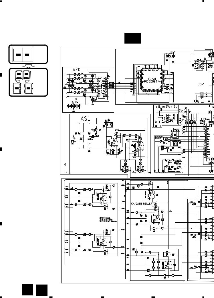
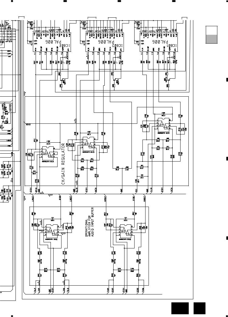
3.2 SCHEMATIC DIAGRAM
Note: When ordering service parts, be sure to refer to “EXPLODED VIEWS AND PARTS LIST” or “ELECTRICAL
|
PARTS LIST”. |
A-a |
A |
|
|
|
|
|
|
|
Large size |
|
A-a A-b |
SCH diagram |
|
|
A-a |
A-b |
Guide page |
A-a |
A-b |
Detailed page |
B
 6R8K 180
SYSTEM POWER
C
TAPE:-7.0dBs
270
4R7K
TAPE:-2.6dBs
270
4R7K
D
270
4R7K
6 A B
1 |
2 |
3 |
4 |

5
OUTPUT OFFSET
INDICATOR
|
33K |
|
2R7K |
4R7/50 |
33K |
OUTPUT OFFSET
INDICATOR
OUTPUT OFFSET
INDICATOR
OUTPUT OFFSET
INDICATOR
2R7K |
UDZS7R5(B) |
1R8K
18K
6 |
|
7 |
|
8 |
|
|
GM-8406ZT,8406ZT-91
A-b |
A |
|
|
|
A DSP UNIT |
TAPE:-3.4dBs
TAPE:-15.5dBs
TAPE:-8.4dBs
B
C
TAPE:+1.2dBs
CD:+8.2dBs
TUNER: -13dBs
SPEED SENSOR PULSE
|
|
TAPE:+23.4dBs |
|
|
D |
|
|
|
CD:+30.4dBs |
|
|
||
|
|
TUNER:+9.4dBs |
|
|
|
|
|
|
NOTE : |
|
|
|
|
|
|
Symbol indicates a resistor. |
Decimal points for resistor |
|
|
|
|
|
No differentiation is made between chip resistors and |
|
|
||
|
|
and capacitor fixed values |
|
|
||
|
|
discrete resistors. |
|
|
||
|
|
are expressed as : |
|
|
||
|
|
Symbol indicates a capacitor. |
2.2 ← |
2R2 |
|
|
|
B AMP UNIT |
No differentiation is made between chip capacitors and |
0.022 |
← R022 |
|
|
CRANKING |
discrete capacitors. |
|
|
|
|
|
|
|
|
|
|
||
PREVENTION CIRCUIT |
|
|
|
|
|
|
|
|
|
|
A |
B |
7 |
|
|
|
|
|
||
5 |
|
6 |
|
7 |
|
8 |
|
|
|
||||
|
|
|

1 |
2 |
3 |
4 |
GM-8406ZT,8406ZT-91
1 |
2 |
|
A-b |
|
|
A |
A-a |
|
|
B
C
180 |
6R8K |
D
8 A-a
SYSTEM POWER
1 |
2 |
3 |
4 |
5 |
6 |
7 |
|
8 |
|
|
|
GM-8406ZT,8406ZT-91 |
|
3 |
4 |
5 |
|
6 |
OUTP IND |
|
OUTPUT OFFSET INDICATOR |
OUT IN |
A-a A-b |
A
270 |
270 |
270 |
4R7K |
4R7K |
4R7K |
|
TAPE:-2.6dBs |
B |
|
|
|
|
|
C |
TAPE:-7.0dBs |
|
|
D
A-a B 9
5 |
|
6 |
|
7 |
|
8 |
|
|
|
||||
|
|
|
1 |
|
2 |
|
3 |
|
4 |
|
|
|
GM-8406ZT,8406ZT-91
A
B
C
D
A-a A-b
UNIT |
TAPE:-3.4dBs |
DSP |
|
A |
|
TAPE:-8.4dBs
TAPE:-15.5dBs


10 A- b
b
1 |
2 |
1 |
2 |
3 |
4 |
3
5
OUTPUT OFFSET
INDICATOR
6 |
4 |
|
|
|
|
|
|
|
5 |
33K |
|
|
|
|
|
|
|
2R7K |
|
|
4R7/50 |
33K |
|
|
T OFFSET |
|
|
|
CATOR |
|
|
7 |
|
|
|
|
OUTPUT OFFSET |
||
|
INDICATOR |
|
|
|
OUTPUT OFFSET |
|
|
-A |
INDICATOR |
|
|
6 |
|
UDZS7R5(B) |
|
b |
2R7K |
||
|
|
1R8K |
|
B8 |
|
18K |
|
|
|
|
|
11 |
|
|
|
|
D |
|
|
TAPE:+1.2dBs
CD:+8.2dBs
TUNER: -13dBs
SPEED SENSOR PULSE
TAPE:+23.4dBs
CD:+30.4dBs
TUNER:+9.4dBs
NOTE :
CRANKING |
B AMP UNIT |
PREVENTION CIRCUIT |
Symbol indicates a resistor.
No differentiation is made between chip resistors and discrete resistors.
Symbol indicates a capacitor.
No differentiation is made between chip capacitors and discrete capacitors.
Decimal points for resistor and capacitor fixed values are expressed as :
2.2 |
← |
2R2 |
|
|
|||
0.022 |
← |
R022 |
|
|
|||
A-a A-b
C |
|
B |
|
A |
|
5
6
|
7 |
|
8406ZT,8406ZT-GM |
|
|
|
|
|
8 |
||
91- |
|
|
1 |
|
2 |
|
3 |
|
4 |
|
|
|
GM-8406ZT,8406ZT-91
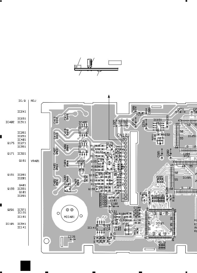
4. PCB CONNECTION DIAGRAM
A |
4.1 DSP UNIT |
|
|
||
|
|
NOTE FOR PCB DIAGRAMS |
|
|
1. The parts mounted on this PCB |
|
|
include all necessary parts for |
|
|
several destination. |
|
|
For further information for |
|
|
respective destinations, be sure |
|
|
to check with the schematic dia- |
|
|
|
|
|
gram. |
2. Viewpoint of PCB diagrams
Connector Capacitor
SIDE A
P.C.Board Chip Part |
SIDE B |
A |
|
DSP UNIT |
|
|
|
|
|
CN906 |
|||||||
|
|
B |
|||||
|
|
|
|
|
|||
|
|
|
|
|
|
|
B
C
D
12 A
1 |
2 |
3 |
4 |
 Loading...