


Service
Manual
ORDER NO.
CRT2242
 SC300,400 AUDIO SYSTEM POWER AMPLIFIER
VEHICLE |
DESTINATION |
PRODUCED AFTER |
TOYOTA PART No. |
ID No. |
PIONEER MODEL No. |
||
LEXUS SC300, |
U.S.A., CANADA |
August 1998 |
86280-24210 |
|
|
|
GM-8886ZT/UC, |
|
|
|
|||||
LEXUS SC400 |
|
|
|
|
|
|
GM-8886ZT-91/UC |
Manufactured for TOYOTA |
|
by PIONEER ELECTRONIC CORPORATION |
PUB. NO. CRT2242 |

GM-8886ZT,8886ZT-91
|
GM-8886ZT/UC, |
|
|
|
|
|
|
|||||
|
GM-8886ZT-91/UC |
|
|
|
|
|
||||||
BU |
|
FL+ FR+ |
RL+ |
RR+ |
CDL+ |
|
|
CDR+ TXM+ |
MUTE |
SGND L+ |
R+ |
|
R1A |
|
RDK RDH |
RDP |
RDM |
UHO |
|
|
UHY ROY |
R1D |
R8G |
R1L |
R1J |
TLMT |
E |
FLFR- |
RLWF- |
WF+ RR- |
CDL- |
SGD4 |
MUTE CDRTXM- |
ACC |
BUS+ BUS- |
L- |
R- |
|
R3T |
R1H |
RDL RDJ |
RDQ RCZ RCY RDN |
UH1 |
2CB |
R2N |
UHZ |
R1B |
RDA RDB |
R1M |
R1K |
|
NOTE:
-The GM-8886ZT-91/UC is supplementary genuine part for a TOYOTA vehicle, and a PIONEER product for recycling stock.
-As for the structure and electrical system, there is no difference between the GM-8886ZT-91/UC and GM-8886ZT/UC.
-The supplementary model is identical with the original ones except for the following items.
|
Description |
Part No. |
|
|
Cover |
CEG1045 |
|
|
Carton |
CHA2114 |
|
|
Contain Box |
CHD2114 |
|
CONTENTS |
|
|
|
1. |
SAFETY INFORMATION ............................................ |
|
2 |
2. |
EXPLODED VIEWS AND PARTS LIST |
.......................3 |
|
3. SCHEMATIC DIAGRAM ............................................. |
|
4 |
|
4. PCB CONNECTION DIAGRAM ................................ |
10 |
||
5. |
ELECTRICAL PARTS LIST ........................................ |
|
18 |
6. ADJUSTMENT.......................................................... |
|
23 |
|
1. SAFETY INFORMATION
7. GENERAL INFORMATION ....................................... |
25 |
|
7.1 |
IC......................................................................... |
25 |
7.2 |
DIAGNOSIS........................................................ |
28 |
|
7.2.1 DISASSEMBLY.......................................... |
28 |
|
7.2.2 CONNECTOR FUNCTION DESCRIPTION ....... |
29 |
7.3 |
EXPLANATION................................................... |
30 |
|
7.3.1 BLOCK DIAGRAM..................................... |
30 |
|
7.3.2 SYSTEM BLOCK DIAGRAM..................... |
31 |
|
7.3.3 SERVICE MODE FOR DSP AMPLIFIER .... |
32 |
8. OPERATIONS AND SPECIFICATIONS..................... |
34 |
|
This service manual is intended for qualified service technicians; it is not meant for the casual do-it-yourselfer. Qualified technicians have the necessary test equipment and tools, and have been trained to properly and safely repair complex products such as those covered by this manual.
Improperly performed repairs can adversely affect the safety and reliability of the product and may void the warranty. If you are not qualified to perform the repair of this product properly and safely, you should not risk trying to do so and refer the repair to a qualified service technician.
2
GM-8886ZT,8886ZT-91
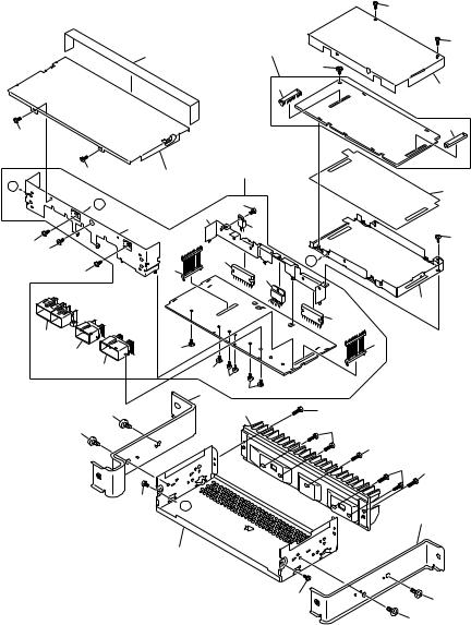
2. EXPLODED VIEWS AND PARTS LIST
2.1 EXTERIOR
26
1
|
1 |
|
5 |
|
|
|
|
A |
|
|
|
|
|
B |
|
|
|
|
21 |
|
|
|
20 |
1 |
|
|
|
1 |
|
|
|
1 |
|
|
19 |
15 |
|
|
|
16 |
|
|
14 |
|
|
|
|
|
|
17 |
14 |
|
|
|
|
|
|
|
8 |
|
|
2 |
|
2 |
|
|
|
1
A
4
NOTE:
|
|
1 |
|
|
|
|
1 |
|
22 |
|
|
|
|
25 |
|
|
23 |
|
7 |
|
|
|
|
|
|
|
24 |
12 |
|
|
|
|
|
|
10 |
13 |
|
|
|
|
30 |
|
|
|
|
|
1 |
27 |
|
B |
|
|
|
|
|
|
28 |
|
|
|
|
|
6 |
|
|
29 |
|
|
|
18 |
|
14 |
|
|
|
14 |
|
|
|
11 |
|
3 |
|
|
|
3 |
|
|
|
3 |
|
|
|
3 |
3 |
|
|
|
|
|
|
|
9 |
1 |
2 |
|
|
|
2 |
-Parts marked by “*”are generally unavailable because they are not in our Master Spare Parts List.
-Screws adjacent to mark on the product are used for disassembly.
-EXTERIOR SECTION PARTS LIST
Mark No. Description |
Part No. |
|
Mark No. Description |
Part No. |
||
1 |
Screw |
BMZ30P060FMC |
16 |
Connector(CN902) |
CKM1293 |
|
2 |
Screw |
BMZ50P080FMC |
17 |
Connector(CN903) |
CKM1245 |
|
3 |
Screw |
CBA1327 |
18 |
Plug(CN905) |
CKS3631 |
|
4 |
Chassis |
CNA1852 |
19 |
Plug(CN906) |
CKS3631 |
|
5 |
Case |
CNB2102 |
20 |
Bracket |
CNC6807 |
|
6 |
Shield |
CNC6809 |
21 |
Holder |
CNC6808 |
|
7 |
Shield |
CNC6810 |
22 |
DSP Unit |
CWM5683 |
|
8 |
Bracket |
CNC7486 |
23 |
Socket(CN51) |
CKS3632 |
|
9 |
Bracket |
CNC7487 |
24 |
Socket(CN52) |
CKS3632 |
|
10 |
Insulator |
CNM5537 |
25 |
Screw |
IMS30P060FMC |
|
11 |
Heat Sink |
CNR1432 |
26 |
Seal |
CNM5381 |
|
12 |
Amp Unit |
CWM5682 |
27 |
IC(IC801) |
TA8221AH1 |
|
13 |
Screw |
BMZ30P060FMC |
28 |
IC(IC821) |
PAL001A |
|
14 |
Screw |
CBA1393 |
29 |
IC(IC851) |
TA8225H-LF1 |
|
15 |
Connector(CN901) |
CKM1222 |
30 |
IC(IC901) |
NJM7805FA |
|
3
|
1 |
|
2 |
|
3 |
|
4 |
|
|
|
|
|
|
GM-8886ZT,8886ZT-91
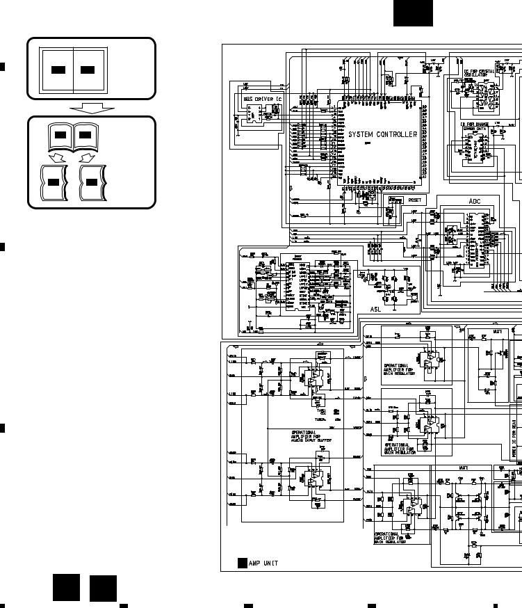
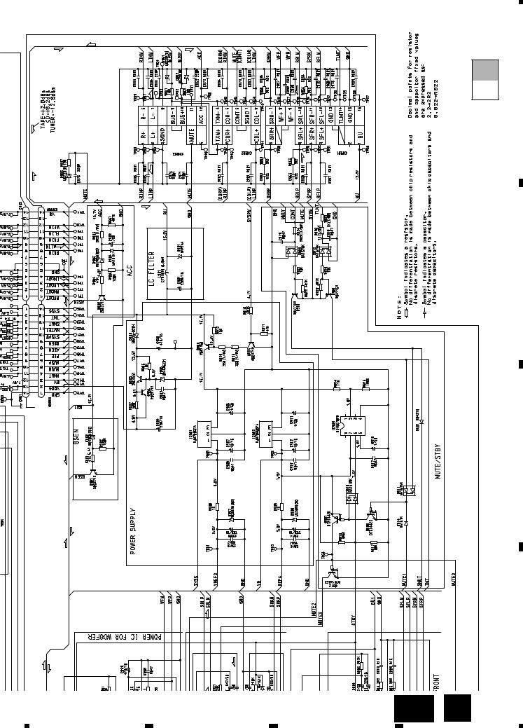
3. SCHEMATIC DIAGRAM
3.1 OVERALL CONNECTION DIAGRAM(GUIDE PAGE)
A
Note: When ordering service parts, be sure to refer to “EXPLODED VIEWS AND PARTS LIST” or “ELECTRICAL PARTS
LIST”.
A-a A-b
Large size SCH diagram
A-a
HA12187FP
A-a |
A-b |
Guide page |
PD5452A
B
A-a |
A-b Detailed page |
C |
|
|
|
|
|
|
|
|
+0.93 |
|
|
|
|
+7.13 |
|
|
|
|
-13.87 |
D |
|
|
|
|
|
A |
B |
B |
|
4 |
|
|
||
|
|
|
|
|
|
1 |
2 |
3 |
4 |

|
5 |
|
6 |
|
7 |
|
8 |
|
|
|
|
|
|
GM-8886ZT,8886ZT-91
A
A-b
A
B
C
D
A B 5
|
5 |
|
6 |
|
7 |
|
8 |
|
|
|
|
|
|
||||
|
|
|
|
|

A
B
C
1 |
2 |
3 |
4 |
GM-8886ZT,8886ZT-91
A-a A-b
PD5452A
HA12187FP
D
6 A-a
|
1 |
|
2 |
|
3 |
|
4 |
|
|
|
|
|
|
||||
|
|
|
|
|

5 |
6 |
7 |
8 |
GM-8886ZT,8886ZT-91
+0.93 |
+7.13 |
-13.87 |
A-a A-b
A
B
C
D
B
A-a B 7
|
5 |
|
6 |
|
7 |
|
8 |
|
|
|
|
|
|
||||
|
|
|
|
|

|
1 |
|
2 |
|
3 |
|
4 |
|
|
|
|
|
|
GM-8886ZT,8886ZT-91
A-a A-b
A
A
B
C
D |
|
|
|
|
8 |
A-b |
|
|
|
|
|
|
|
|
|
1 |
2 |
3 |
4 |
|
5 |
|
6 |
|
7 |
|
8 |
|
|
|
|
GM-8886ZT,8886ZT-91
A-a A-b
A-b B 9
A
B
C
D
5 |
6 |
7 |
8 |

|
1 |
|
2 |
|
3 |
|
4 |
|
|
|
|
|
|
GM-8886ZT,8886ZT-91
4. PCB CONNECTION DIAGRAM
4.1 DSP UNIT
A
NOTE FOR PCB DIAGRAMS
1.The parts mounted on this PCB include all necessary parts for several destination.
For further information for respective destinations, be sure
to check with the schematic diagram.
2. Viewpoint of PCB diagrams
Connector Capacitor
SIDE A
P.C.Board Chip Part |
SIDE B |
A DSP UNIT
B
C
|
|
|
|
|
|
|
|
|
|
|
|
|
|
|
|
|
|
|
|
|
|
|
|
|
|
|
|
|
|
|
|
|
|
|
|
|
|
|
|
|
|
|
|
|
|
|
|
|
|
|
|
|
|
|
|
|
|
|
|
|
|
|
|
|
|
|
|
|
|
|
|
D |
B |
CN906 |
||||||
|
||||||||
10 A
|
1 |
|
2 |
|
3 |
|
4 |
|
|
|
|
|
|
||||
|
|
|
|
|
|
5 |
|
6 |
|
7 |
|
8 |
|
|
|
|
|
|
GM-8886ZT,8886ZT-91
A
SIDE A
B
C
B CN905 |
D |
|
A 11
|
5 |
|
6 |
|
7 |
|
8 |
|
|
|
|
|
|
||||
|
|
|
|
|
 Loading...