


HTP-55
ORDER NO.
PIONEER CORPORATION 4-1, Meguro 1-chome, Meguro-ku, Tokyo 153-8654, Japan
PIONEER ELECTRONICS SERVICE, INC. P.O. Box 1760, Long Beach, CA 90801-1760, U.S.A.
PIONEER ELECTRONIC (EUROPE) N.V. Haven 1087, Keetberglaan 1, 9120 Melsele, Belgium
PIONEER ELECTRONICS ASIACENTRE PTE. LTD. 253 Alexandra Road, #04-01, Singapore 159936
PIONEER CORPORATION 1999
c
HTP-55
RRV2164
T – IZE OCT. 1999 Printed in Japan
Type
Model
Power Requirement
HTP-55
SDXCN1 AC110V/120-127V/220V/240V With the voltage selector
THIS MANUAL IS APPLICABLE TO THE FOLLOWING MODEL(S) AND TYPE(S).
HOME THEA TER SYSTEM
1. SAFETY INFORMATION
......................................
2
2. EXPLODED VIEWS AND PARTS LIST
...............
3
3. BLOCK DIAGRAM AND SCHEMATIC DIAGRAM
.....
6
4. PCB CONNECTION DIAGRAM
.........................
17
5. PCB PARTS LIST
...............................................
22
6. ADJUSTMENT
....................................................
24
CONTENTS
7. GENERAL INFORMATION
................................
26
7.1 PARTS
..........................................................
26
7.1.1 IC
............................................................
26
7.1.2 DISPLAY
.................................................
33
8. PANEL FACILITIES AND SPECIFICATIONS
.......
35
The voltage can be converted by
the following method.
Component
Model
Service Manual Remarks
HTP-55/SDXCN1
AUDIO MULTI-CHANNEL RECEIVER
(VSX-108/SDXCN1)
This manual
REAR SPK. BOX&LABEL
SP108250297S
SUBWOOFER BOX&LABEL
SP10830001S
FRONT SPK. BOX&LABEL
SP108400297AS
CENTER SPK. BOX&LABEL
SP108401297BS
The HTP-55 is a combination of the components in the Table below.
2
HTP-55
1. SAFETY INFORMATION
This service manual is intended for qualified service technicians ; it is not meant for the casual do-it-
yourselfer. Qualified technicians have the necessary test equipment and tools, and have been trained
to properly and safely repair complex products such as those covered by this manual.
Improperly performed repairs can adversely affect the safety and reliability of the product and may
void the warranty. If you are not qualified to perform the repair of this product properly and safely, you
should not risk trying to do so and refer the repair to a qualified service technician.
WARNING
This product contains lead in solder and certain electrical parts contain chemicals which are known to the state of California to cause
cancer, birth defects or other reproductive harm.
Health & Safety Code Section 25249.6 – Proposition 65
NOTICE
(FOR CANADIAN MODEL ONLY)
Fuse symbols (fast operating fuse) and/or (slow operating fuse) on PCB indicate that replacement parts must
be of identical designation.
REMARQUE
(POUR MODÈLE CANADIEN SEULEMENT)
Les symboles de fusible (fusible de type rapide) et/ou (fusible de type lent) sur CCI indiquent que les pièces
de remplacement doivent avoir la même désignation.
ANY MEASUREMENTS NOT WITHIN THE LIMITS
OUTLINED ABOVE ARE INDICATIVE OF A POTENTIAL
SHOCK HAZARD AND MUST BE CORRECTED BEFORE
RETURNING THE APPLIANCE TO THE CUSTOMER.
2. PRODUCT SAFETY NOTICE
Many electrical and mechanical parts in the appliance
have special safety related characteristics. These are
often not evident from visual inspection nor the protection
afforded by them necessarily can be obtained by using
replacement components rated for voltage, wattage, etc.
Replacement parts which have these special safety
characteristics are identified in this Service Manual.
Electrical components having such features are identified
by marking with a
on the schematics and on the parts list
in this Service Manual.
The use of a substitute replacement component which does
not have the same safety characteristics as the PIONEER
recommended replacement one, shown in the parts list in
this Service Manual, may create shock, fire, or other hazards.
Product Safety is continuously under review and new
instructions are issued from time to time. For the latest
information, always consult the current PIONEER Service
Manual. A subscription to, or additional copies of, PIONEER
Service Manual may be obtained at a nominal charge from
PIONEER.
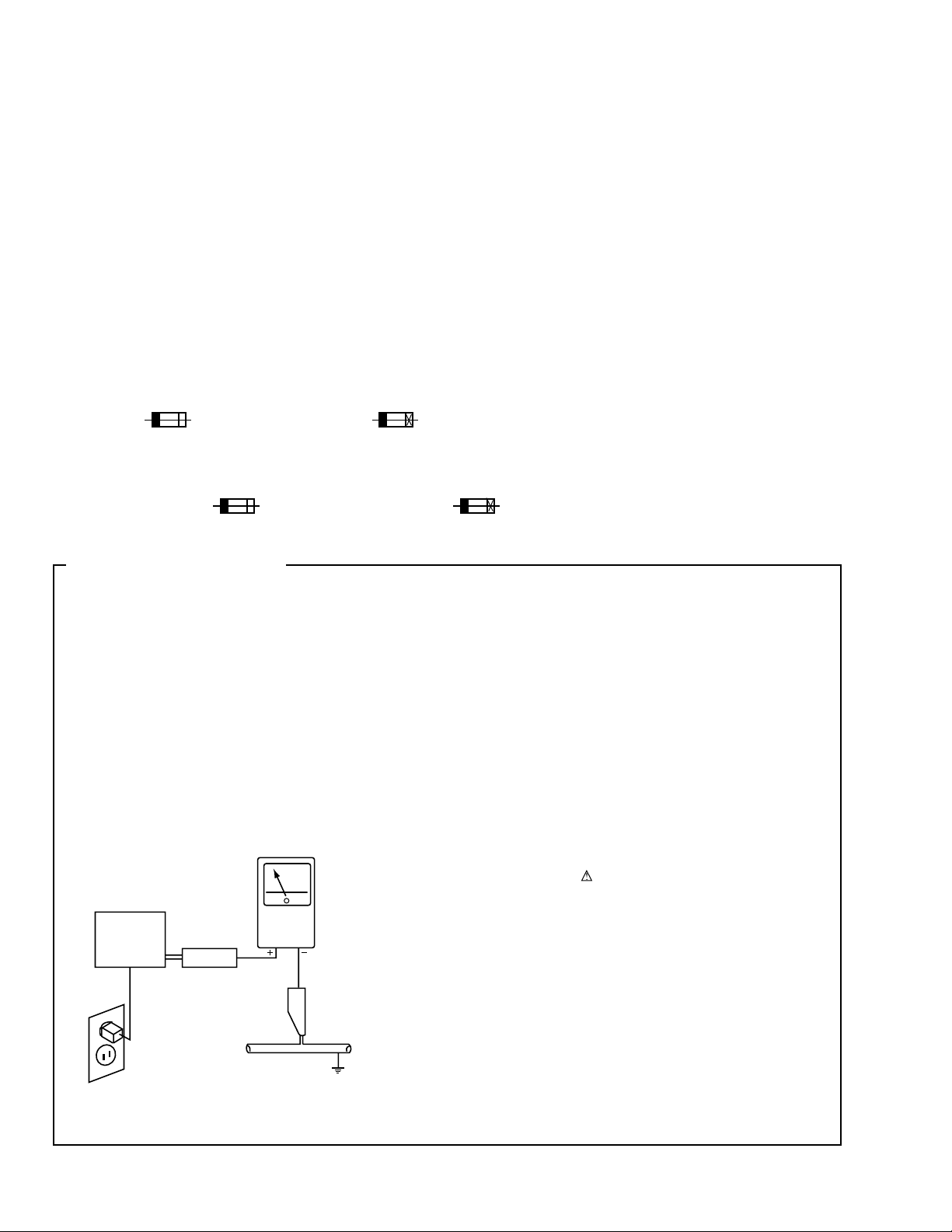
1. SAFETY PRECAUTIONS
The following check should be performed for the
continued protection of the customer and service
technician.
LEAKAGE CURRENT CHECK
Measure leakage current to a known earth ground (water
pipe, conduit, etc.) by connecting a leakage current tester
such as Simpson Model 229-2 or equivalent between the
earth ground and all exposed metal parts of the appliance
(input/output terminals, screwheads, metal overlays, control
shaft, etc.). Plug the AC line cord of the appliance directly
into a 120V AC 60Hz outlet and turn the AC power switch
on. Any current measured must not exceed 0.5mA.
(FOR USA MODEL ONLY)
Leakage
current
tester
Reading should
not be above
0.5mA
Device
under
test
Test all
exposed metal
surfaces
Also test with
plug reversed
(Using AC adapter
plug as required)
Earth
ground
AC Leakage Test
3
HTP-55
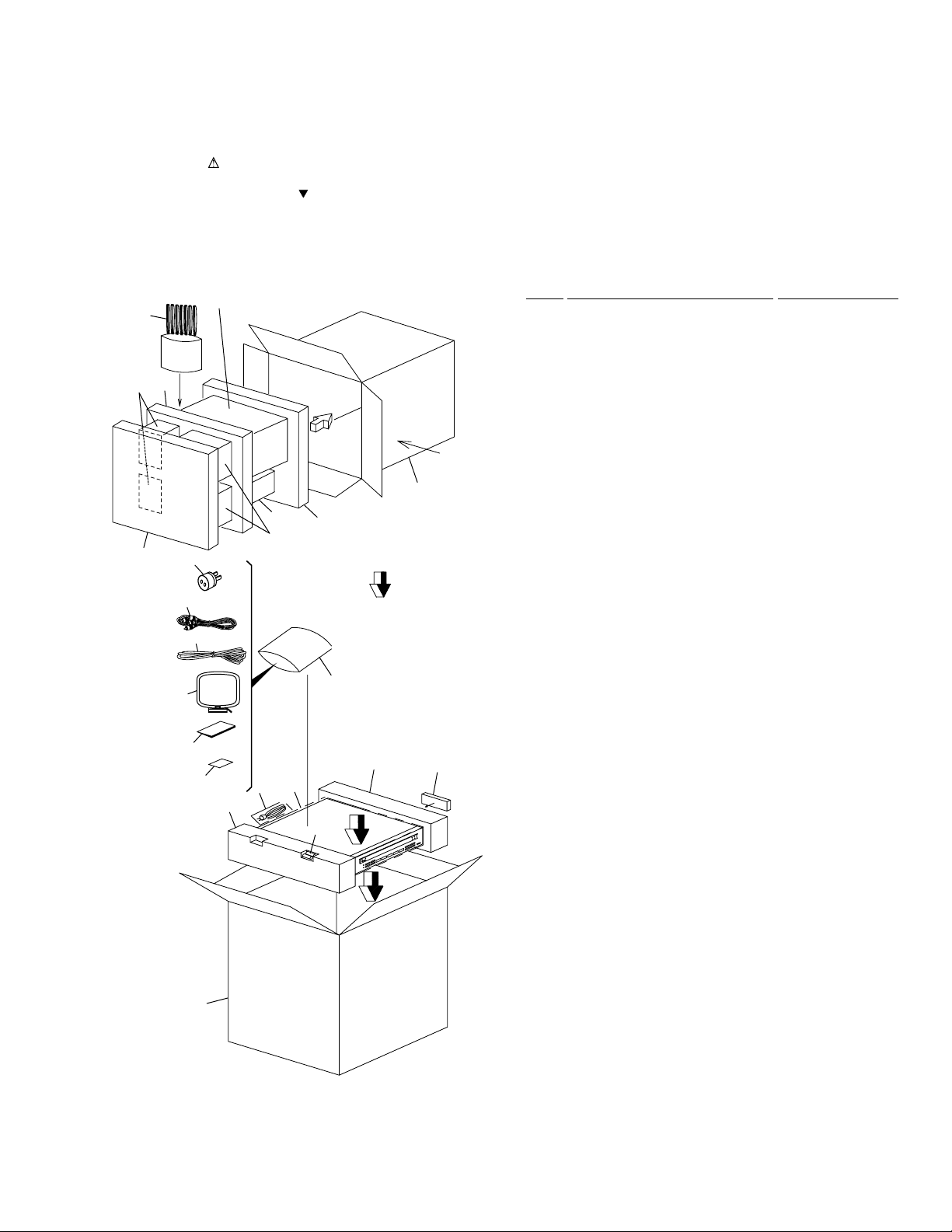
2.1 PACKING
•
PACKING PARTS LIST
Mark No. Description Part No.
2. EXPLODED VIEWS AND PARTS LIST
NOTES:
•
Parts marked by "NSP" are generally unavailable because they are not in our Master Spare Parts List.
•
The mark found on some component parts indicates the importance of the safety factor of the part.
Therefore, when replacing, be sure to use parts of identical designation.
•
Screws adjacent to mark on the product are used for disassembly.
1 AM Loop Antenna 01582100001S
2 FM Antenna 06410001003S
3 Operating Instructions 152205521297
(English, Spanish)
4 Polyform L 14901081000S
5 Polyform R 14901082000S
6 Remote Control Unit 18201080001S
7 HTP-55SD/Carton Box 151205510297
8 Poly. Bag (4 × 20) 15004011210S
9 Poly. Bag (10 × 15) 15010015510S
10 Poly. Bag (20 × 26) 15020026510S
11 RCA Cable PDE1248
NSP 12 Dry Cell Battery (LR6, AA) • • • • •
NSP 13 Warranty Card • • • • •
14 Speaker Cord Set SP108SPKWIRE
15 Rear SPK. Box&Label SP108250297S
16 Subwoofer Box&Label SP10830001S
17 Front SPK. Box&Label SP108400297AS
18 Center SPK. Box&Label SP108400297BS
19 AC Adapter Plug 02430000008S
20 VSX108SPK. Polyform 14901080000S
21 VSX108SPK. Polyform 14901083000S
22 VSX108SPK. Polyform 14901084000S
23 S-HTP-55 SPK. Carton Box 15340552000S
FRONT
2
11
14
23
22
21
19
18
17
15
20
16
Refer to "2.3 SUBWOOFER BOX&LABEL".
1
4
10
8
9
12
7
6
3
13
5
4
HTP-55
A
A
4
25
25
20
5
27
29
3
25
Bottom Cover
25
25
25
25
25
22
22
25
18
19
19
17
19
7
25
25
25
25
25
25
25
6
14
15
12
13
11
10
30
9
24
26
26
25
25
34
25
35
8
25
25
2
28
25
33
36
31
25
25
32
28
28
23
25
25
25
25
25
21
1
25
25
26
26
26
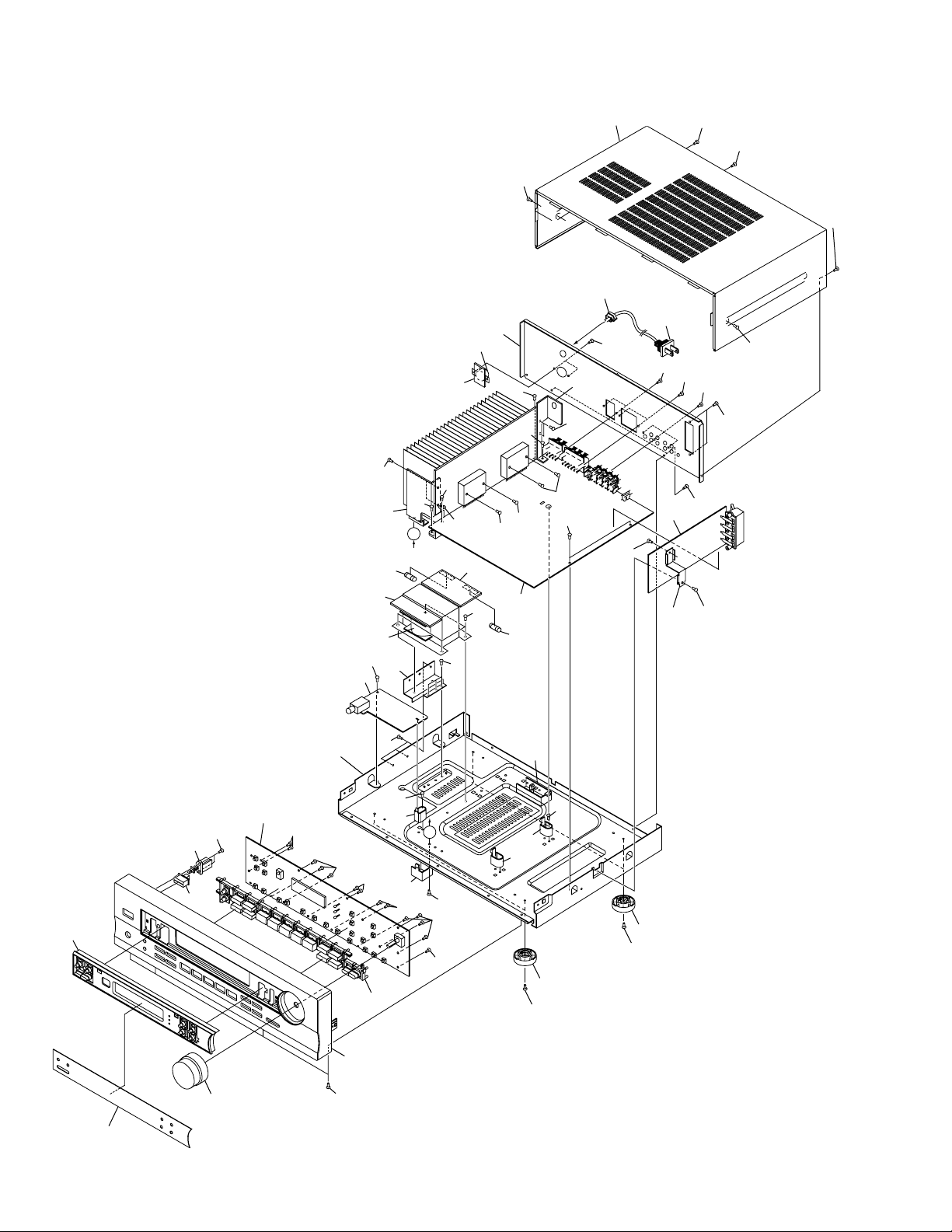
2.2 EXTERIOR
5
HTP-55
•
EXTERIOR PARTS LIST
Mark No. Description Part No.
NSP 1 TUNER PCB AZW7259
(Circuit Parts Assy)
NSP 2 MAIN PCB AZW7259
(Circuit Parts Assy)
NSP 3 PHONE PCB AZW7259
(Circuit Parts Assy)
NSP 4 AC O/P PCB AZW7259
(Circuit Parts Assy)
NSP 5 AC I/P PCB AZW7259
(Circuit Parts Assy)
NSP 6 PW SW PCB AZW7259
(Circuit Parts Assy)
NSP 7 DISPLAY PCB AZW7259
(Circuit Parts Assy)
NSP 8 110/220V PCB AZW7259
(Circuit Parts Assy)
9 AC Cord Stopper 13010550000S
10 Display Lens 11701080101S
11 Volume Knob 12701081010S
12 Front Panel 10801080010S
13 Front Cabinet 10101080001AS
14 Power Button 12801080001S
15 Function Button 12801082001S
16 • • • • •
17 Mounting Bracket A 12901089000S
18 Mounting Bracket B 12901089100S
19 PCB Holder 13001082000S
20 Mounting Holder 13301082310S
21 PCB Mounting Bracket 13301083310S
22 Insullator 13821007010S
23 Top Cover 18001083010S
24 Rear Cover 18001085201S
25 Screw BBZ30P080FZK
26 Screw BBZ30P100FZK
27 Screw FBT40P080FZK
28 Screw 14453016202S
29 Power transformar 01801088562S
(AC110V/120-127V/220V/240V)
30 AC Power Cord 02360020007S
31 Fuse (F801 : 4A/250V) 05005020402S
NSP 32 Metal Washer • • • • •
NSP 33 PCB Mounting Bracket • • • • •
NSP 34 Heatsink Mounting Bracket • • • • •
35 Voltage Switch 2P 02082400051S
36 Fuse (F802 : 2A/250V) 05005020209S
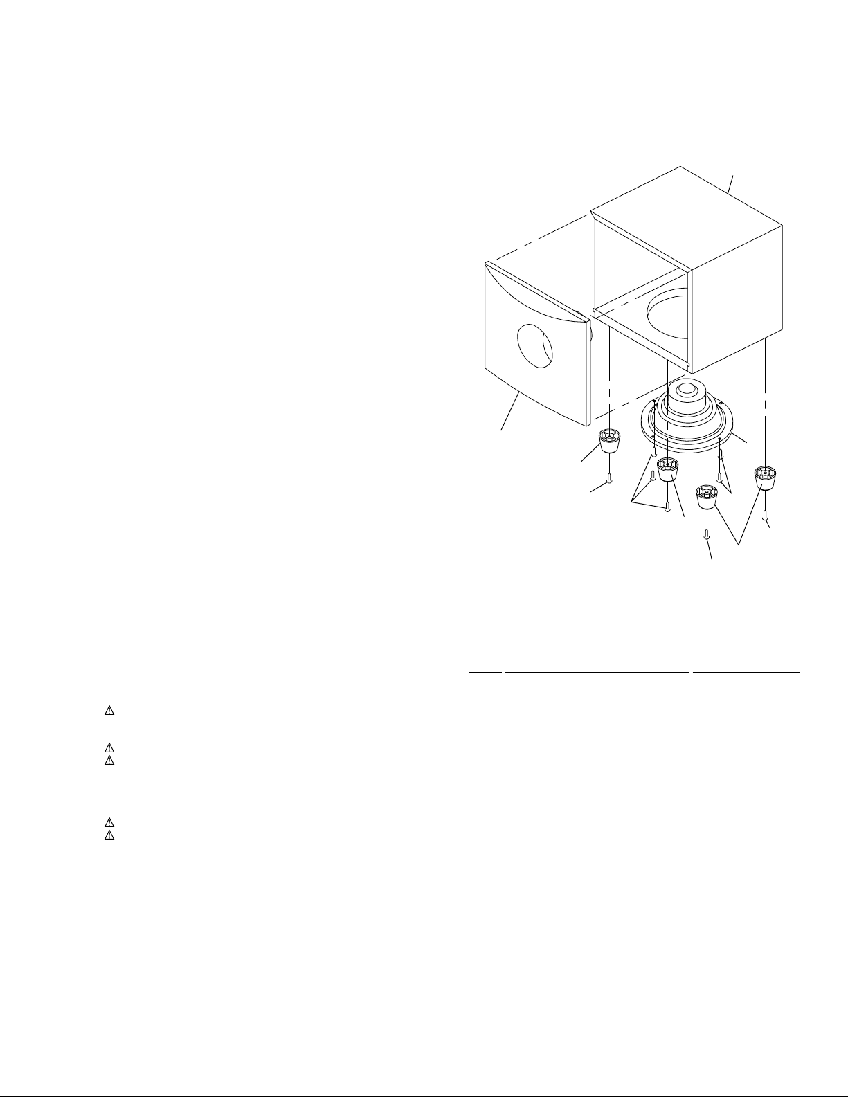
2.3 SUBWOOFER BOX&LABEL
Woofer Speaker Panel
SPK. Box
1
Screw
Screw
Screw
Screw
Screw
Plastic Foot
Plastic Foot
Plastic Foot
•
SUBWOOFER BOX&LABEL PARTS LIST
Mark No. Description Part No.
1 170MM SPK. 6/6 OHM 02917006412S
HTP-55
6
A
B
C
D
1
23
4
1234
DISPLAY PCB
TUNER PCB
B 1/2, B 2/2
CN102
CN701A
CN701
CN708A
CN708
CN201
L
R
CD
G
A
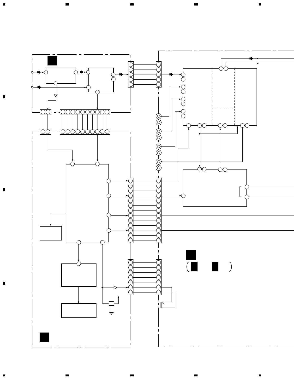
MAIN PCB
B
FM
ANTENNA
AM
ANTENNA
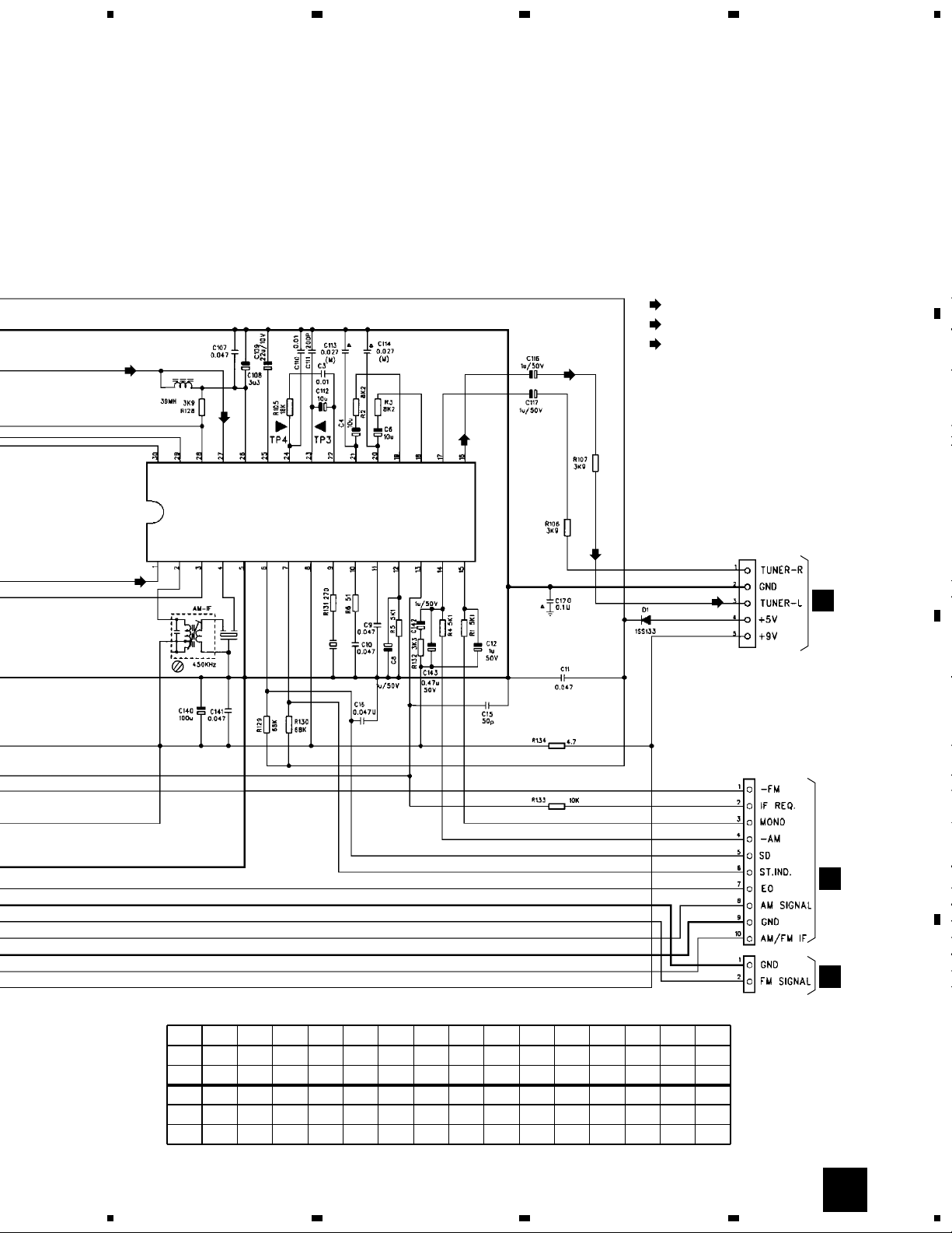
IC101
LA1186N
FM FRONT END
IC102
00201838-040
(LA1838)
ELECTRIC
TUNING
AM
Q102
FM IN AM IN
DATA
DATA
DATA
MUTE
RELAY
REMOTE
FM
FM
TUNER
TUNER-R
GND
TUNER-L
AM/FM IF
GND
AM SIG.
EO
ST. IND
SD
– AM
MONO
IF REQ.
– FM
+5V
+9V
1
1
7
36
9
8
1
1 21 2 3 4 5 6 7 8 9 10
10 91 2 8 7 6 5 4 3 2 1
2
3
4
5
1
2
3
4
5
CN6
1
2
3
4
5
6
7
CN7CN707
CN702
1
2
3
4
5
6
7
1
2
3
4
5
6
7
8
9
10
11
12
13
1
2
3
4
5
6
7
8
9
10
11
12
13
TUNER
L
R
9
34
L
R
8
35
L
R
10
1 40 3
61
74
9
50
53
17
312
6
27
30
17
16
75
51
62
33
L
L
R
R
39 4
24 21
31
33
26 17
L
R
L
C
S
R
L
R
L
TONE
OUT
SEL
OUT
IN
OUT
CV,
SV
OUT
R
23 20
L
R
DATA
CLK
E1
DATA
CLK
E2
DGND
MUTE
OVER
SP.OFF
RELAY
2-CH
DC/O
AC3.8V
-25V
+5V
GND
SR
GND
AC3.8V
Q703,
Q704
+5V
12
FM SIG
GND
L
R
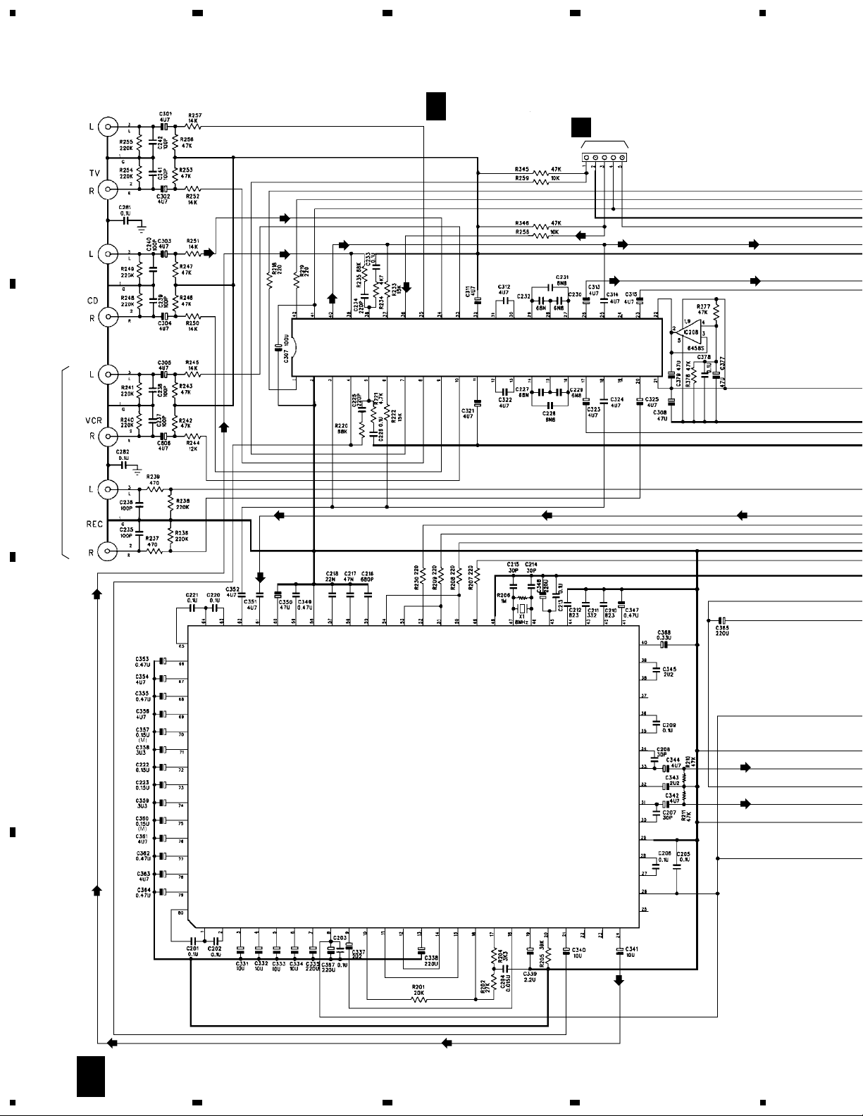
TV
L
R
VCR
IN
L
R
VCR
OUT
CONTROL
OUT
IC203
00262419-010
(M62419)
Digital Sound Controller
VR
TONE
FADER
SELECTOR
IC201
00201041-040
(LV1041M)
Dolby Pro-Logic Decoder
KEY SW
IC701
00272358-040
(LC72358N)
Control µ-Com.
IC702
00202879-040
(BU2879AK)
FL Driver IC
IC703
06104421-000
IR Receiver
V1
FL TUBE
04991693-001
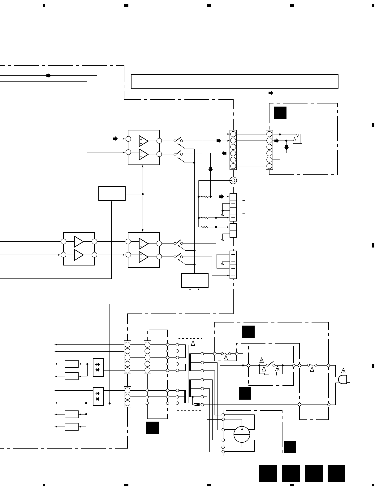
3. BLOCK DIAGRAM AND SCHEMATIC DIAGRAM
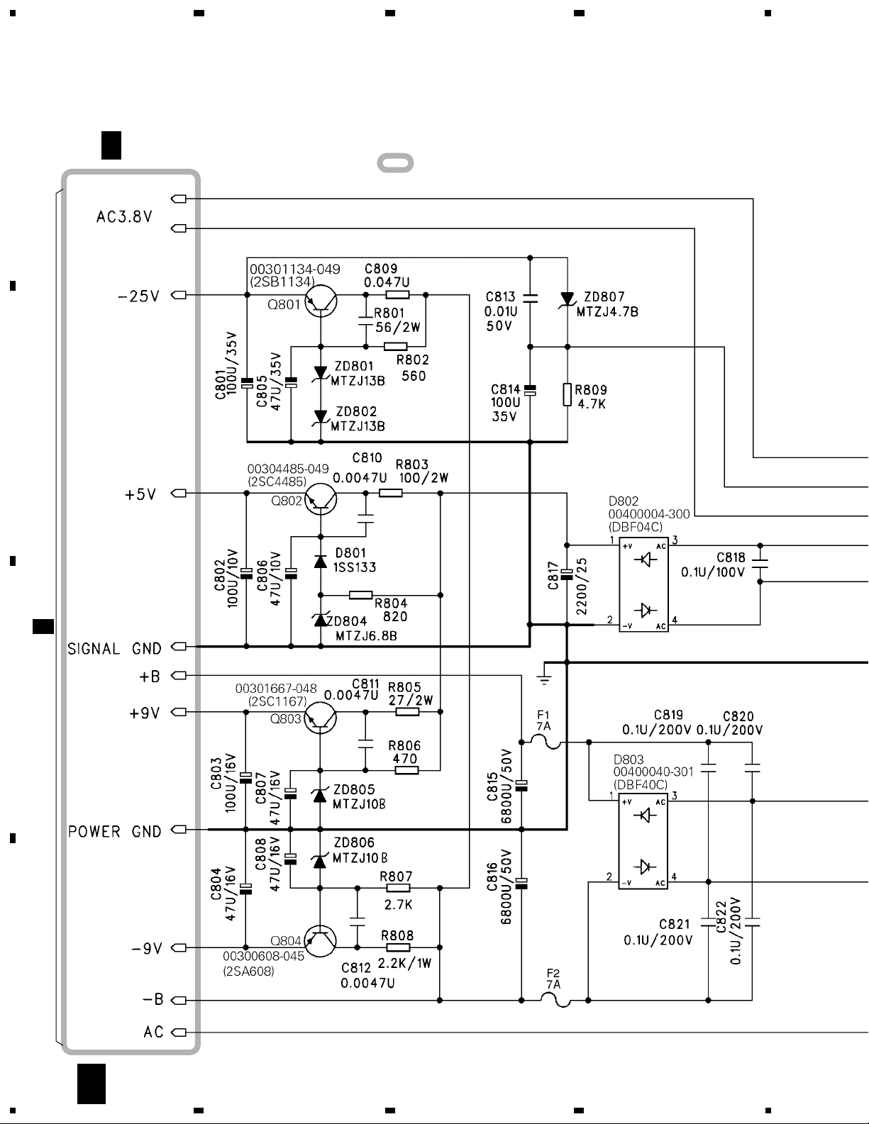
3.1 BLOCK DIAGRAM, OVERALL WIRING DIAGRAM, AC O/P, AC I/P,
PW SW and 110/220V PCBS
HTP-55
7
A
B
C
D
5
678
5
6
7
8
PHONE PCB
AC O/P PCB
AC I/P PCB
PW SW PCB
CN14 CN14A
C
D
E
110/220V PCB
H
F
T1
POWER
TRANSFORMER
01801088562S
AC IN
AC
110-120V/
220-240V
50/60Hz
LIVE
NEUTRAL
Q201-Q204
6 8
4
CN207
CN207A
1.9V
CT
1.9V
16.5V
1
2
3
4
5
1
2
3
4
5
CN208
REG.
1
2
3
1
2
3
4
5
6
1
2
3
4
5
6
R
L
GND
L-SP
R-ST
SP-OFF
PHONES
: AUDIO SIGNAL ROUTE
2
10
6
14
7
10
6
14
7
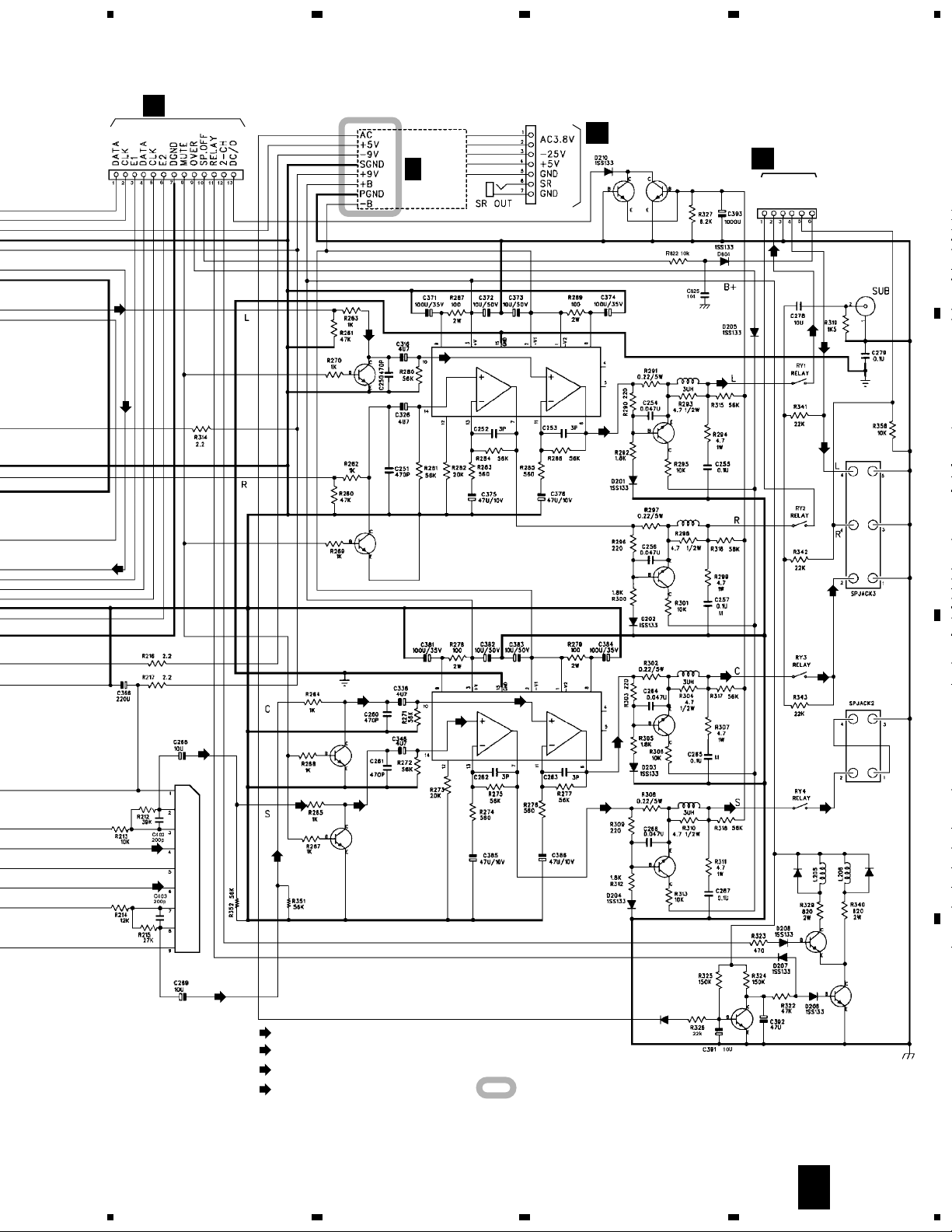
IC202
00206458-040
(LA6458S)
Dual Operational Amp.
IC205
STK407-070
2ch AF Power Amp.
IC204
STK407-070
2ch AF Power Amp.
MUTING
Q209-Q211
D802
+5V
+9V
+B
–B
–25V
–9V
D803
J6
120V
10V
0V
120V
110V
0V
5
4
3
2
6
(A)
(B)
(C)
(C)
(B)
(D)
(D)
(A)
W2 W1
J5
J7
Q802
Q803
Q801
Q804
RY4
PS1
POWER
F801
T4AL250V
C823
0.01/300V
R821
120/1W
SW2
VOLTAGE
SWITCH 2P
02082400051S
RY3
RY2
RY1
RELAY
DRIVER
AC
3.8V
REG.
REG.
REG.
F802
T2AL250V
02041100-004
05005020402S
05005020209S
• NOTE FOR FUSE REPLACEMENT
FOR CONTINUED PROTECTION AGAINST RISK OF FIRE.
REPLACE WITH SAME TYPE AND RATINGS ONLY.
CAUTION -
L
R
FRONT
[Jack 6 (1/2)]
CENTER
[Jack 6 (2/2)]
SURROUND
[Jack 7]
SUB WOOFER
[Jack 5]
RELAY
DRIVER
Note : When ordering service parts, be sure to refer to "EXPLODED VIEWS and PARTS LIST" or "PCB PARTS LIST".
HFED
HTP-55
8
A
B
C
D
1
23
4
1234
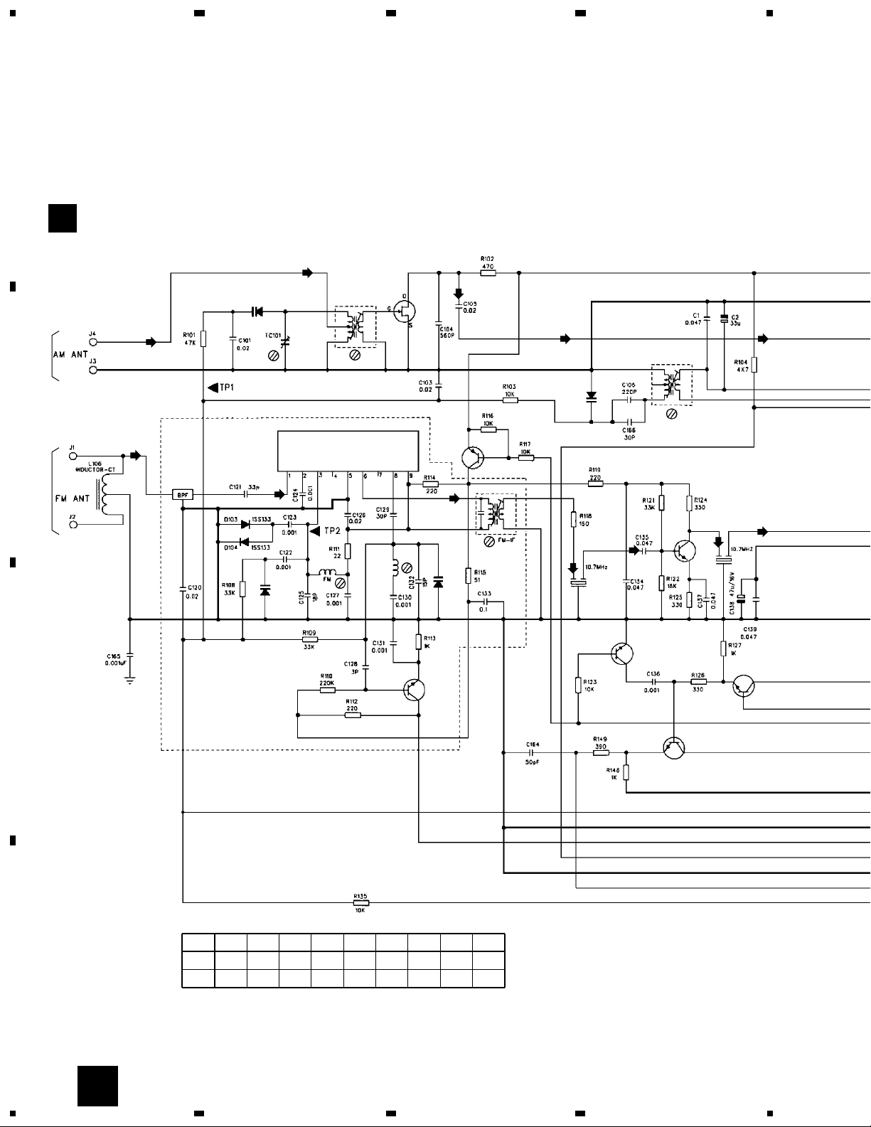
FM
300Ω
AM
LOOP
ANTENNA
IC101
LA1186N
T102
01620360-023
D102
00400321-500
(SVC321)
Q101
00300715-041
(2SK715)
T101
01621032-104
T103
01627539-032
L102
01705037-350
L104
01706036-350
FM
D106
SVC201SPA
D105
SVC201SPA
Q103
00300608-045
(2SA608)
D101
00400321-500
(SVC321)
BPS101
02876108-002
TC101
01410200-003
CF102
02810700-009
Q106
00302999-044
(2SC2999)
Q107
00302999-044
(2SC2999)
Q104
00300536-046
(2SC536)
Q102
00302999-044
(2SC2999)
CF101
02810700-009
Q105
00302999-044
(2SC2999)
123456789
AM 0.0 0.0 0.0 0.0 0.0 0.0 0.0 0.0 0.0
FM 0.9 1.5 4.8 0.0 0.0 4.8 0.0 4.0 4.8
IC101
(volt)
AM
AM
AM
AM
AM
FM
FM
FM
FM
FM
FM
FM
TUNER PCB
A
3.2 TUNER PCB
A
HTP-55
9
A
B
C
D
5
678
5
6
7
8
CN201
B
CN701
CN701A
02520012-202
CN708A
CN102
02520005-205
IC102
00201838-040
(LA1838)
L101
01500393-001
GM74A
02810700-025
G
CN708
G
CF103
02800450-000
T104
01627580-041
(volt)
123456789
AM 3.8 13.0 3.8 3.8 0.0 5.1 5.1 13.0 2.3
FM 3.8 13.0 3.8 3.8 0.0 4.9 4.9 13.0 2.3
IC102
10 11
1.6 0.0
1.6 0.4
12 13
0.0 0.0
0.0 0.0
14 15
8.0 12.0
12.0 12.0
16 17 18 19 20 21 22 23 24
AM 4.5 4.5 4.5 4.5 3.5 3.5 2.8 0.0 0.6
FM 4.5 4.5 4.5 4.5 3.5 3.5 2.8 3.0 0.0
25 26
0.5 3.8
0.0 4.2
27 28
3.8 3.8
4.0 3.8
29 30
3.8 2.0
3.8 2.2
: TUNER AUDIO SIGNAL ROUTE (L ch)
: AM SIGNAL ROUTE
AM
T
: FM SIGNAL ROUTE
FM
AM
AM
T
T
T
T
FM
A
HTP-55
10
A
B
C
D
1
23
4
1234
CN102
A
JACK4
JACK3
JACK2
IN
OUT
JACK1
VCR
CN201
IC203
00262419-010
(M62419)
IC201
00201041-040
(LV1041M)
05208000-000
S
C
T
T
B 1/2
MAIN PCB
1/2
B
3.3 MAIN PCB (1/2)
HTP-55
11
A
B
C
D
5
678
5
6
7
8
CN707
G
CN14A
C
JACK6
JACK7
FRONT
CENTER
SURROUND
CN7
CN14
R
L
GND
L-SP
R-ST
SP-OFF
CN702
G
CN6
IC202
00206458-040
(LA6458S)
IC205
STK407-070
IC204
STK407-070
Q213
00310536-046
Q204
00303576-040
Q203
00302576-040
Q202
00302576-040
Q201
00302576-040
Q212
00310536-046
L201
01500030-006
L202
01500030-006
04610400-006
04620800-001
L203
01500030-006
L204
01500030-006
Q210
Q205-Q211 :
00310536-046
Q209
Q211
Q208
Q207
Q206
Q205
D212
00494001-300
D211
00494001-300
D209
00494001-300
B
2/2
: AUDIO SIGNAL ROUTE (L ch)
: AUDIO SIGNAL ROUTE (Center)
C
: AUDIO SIGNAL ROUTE (Surround)
S
S
S
S S
S
S S S
C
C
C
C
C
C
C
C
C
: The power supply is shown with the marked box.
: TUNER AUDIO SIGNAL ROUTE (L ch)
T
1/2
B
HTP-55
12
A
B
C
D
1
23
4
1234
B
1/2
: The power supply is shown with the marked box.
B 2/2
MAIN PCB
2/2
B
3.4 MAIN (2/2) and PHONE PCBS
 Loading...