


Service |
|
Manual |
ORDER NO. |
|
|
GM-D505/XH/EW |
CRT3076 |
5 CHANNEL POWER AMPLIFIER
GM-D505XH/EW, XR/EW GM-D505 XH/ES, XR/ES
For details, refer to "Important symbols for good services".
PIONEER CORPORATION |
4-1, Meguro |
1-Chome, Meguro-ku, Tokyo 153-8654, Japan |
PIONEER ELECTRONICS (USA) INC. |
P.O.Box 1760, Long Beach, CA 90801-1760 U.S.A. |
|
PIONEER EUROPE NV Haven 1087 |
Keetberglaan 1, |
9120 Melsele, Belgium |
PIONEER ELECTRONICS ASIACENTRE PTE.LTD. 253 Alexandra Road, #04-01, Singapore 159936
C PIONEER CORPORATION 2003 |
K-ZZB. MAY 2003 Printed in Japan |
|
1 |
|
2 |
|
3 |
|
4 |
|
|
|
A[ Important symbols for good services ]
In this manual, the symbols shown-below indicate that adjustments, settings or cleaning should be made securely. When you find the procedures bearing any of the symbols, be sure to fulfill them:
1.Product safety
You should conform to the regulations governing the product (safety, radio and noise, and other regulations), and should keep the safety during servicing by following the safety instructions described in this manual.
2. Adjustments
 To keep the original performances of the product, optimum adjustments or specification confirmation is indispensable. In accordance with the procedures or instructions described in this manual, adjustments should be performed.
B
3. Cleaning
For optical pickups, tape-deck heads, lenses and mirrors used in projection monitors, and other parts requiring cleaning, proper cleaning should be performed to restore their performances.
4. Shipping mode and shipping screws
To protect the product from damages or failures that may be caused during transit, the shipping mode should be set or the shipping screws should be installed before shipping out in accordance with this manual, if necessary.
5. Lubricants, glues, and replacement parts
C |
Appropriately applying grease or glue can maintain the product performances. But improper lubrication or applying |
|
glue may lead to failures or troubles in the product. By following the instructions in this manual, be sure to apply the |
||
|
||
|
prescribed grease or glue to proper portions by the appropriate amount.For replacement parts or tools, the prescribed |
|
|
ones should be used. |
D
SAFETY INFORMATION
|
|
CAUTION |
|
|
This service manual is intended for qualified service technicians; it is not meant for the casual do-it-yourselfer. |
|
|
|
|
|
Qualified technicians have the necessary test equipment and tools, and have been trained to properly and safely repair |
|
|
complex products such as those covered by this manual. |
|
|
Improperly performed repairs can adversely affect the safety and reliability of the product and may void the warranty. |
E |
If you are not qualified to perform the repair of this product properly and safely, you should not risk trying to do so |
|
and refer the repair to a qualified service technician. |
||
F
2 |
GM-D505/XH/EW |
1 |
|
2 |
|
3 |
|
4 |
|
|
|
||||
|
|
|

5 |
|
6 |
|
7 |
|
8 |
|
|
|
CONTENTS
|
SAFETY INFORMATION............................................ |
2 |
5. |
ELECTRICAL PARTS LIST........................................ |
21 |
||
1. |
SPECIFICATIONS ....................................................... |
3 |
6. |
ADJUSTMENT ......................................................... |
25 |
||
2. |
EXPLODED VIEWS AND PARTS LIST ...................... |
4 |
7. |
GENERAL INFORMATION....................................... |
26 |
||
|
2.1 |
PACKING.............................................................. |
4 |
|
7.1 DIAGNOSIS ....................................................... |
26 |
|
|
2.2 |
EXTERIOR ............................................................ |
6 |
|
7.1.1 |
DISASSEMBLY......................................... |
26 |
3. |
SCHEMATIC DIAGRAM............................................. |
8 |
|
7.1.2 |
CONNECTOR FUNCTION DESCRIPTION ...... |
27 |
|
|
3.1 |
SCHEMATIC DIAGRAM(GUIDE PAGE) .............. |
8 |
|
7.2 IC ........................................................................ |
|
28 |
4. |
PCB CONNECTION DIAGRAM................................ |
16 |
|
7.3 CIRCUIT DESCRIPTIONS .................................. |
29 |
||
|
4.1 |
AMP UNIT.......................................................... |
16 |
8. |
OPERATIONS ........................................................... |
30 |
|
|
4.2 |
NETWORK PCB ................................................. |
20 |
|
|
|
|
|
4.3 |
CONNECTOR PCB ............................................. |
20 |
|
|
|
|
1. SPECIFICATIONS
Power source............................................................................................................ |
14.4 V DC (10.8 — 15.1 V allowable) |
|||||
Backup current ................................................................................................................................................ |
|
|
3 mA or less |
|||
Grounding system .......................................................................................................................................... |
|
|
Negative type |
|||
Current consumption .................................................................................................... |
43.8 A (at continuous power, 4 Ω |
) |
||||
Average current drawn* ...................................................................................................... |
10.9 A (4 Ω for five channels) |
|||||
Fuse ........................................................................................................................................................................ |
350 (W) × 52 (H) × |
25 A × |
3 |
|||
Dimensions ...................................................................................................................... |
268 (D) mm |
|||||
Weight .................................................................................................................... |
3.9 kg (Leads for wiring not included) |
|||||
Maximum power output .................................................................................................... |
Channel A/B: 100 W × |
4 (4 Ω |
) |
|||
|
Channel SUB: 300 W × |
1 (4 Ω |
) / 600 W × |
1 (2 Ω |
) |
|
Continuous power output ............................................................................................ |
65 W × |
4 (4 Ω |
) + 225 W × |
1 (4 Ω |
) |
|
|
(56 W × 4 (4 Ω ) + 350 W × |
1 (2 Ω |
)) |
|||
|
|
(DIN45324, +B=14.4 V) |
||||
Load impedance .................................................................................................... |
4 Ω (Channel A/B: 4 — 8 Ω |
allowable) |
||||
|
(Channel SUB: 2 — 8 Ω |
allowable) |
||||
Frequency response .................................................................................. |
Channel A/B: 10 — 40,000 Hz (+0 dB, –1 dB) |
|||||
|
Channel SUB: 5 — 240 Hz (+0.5 dB, –3 dB) |
|||||
Signal-to-noise ratio ...................................................................................................................... |
|
95 dB (IEC-A network) |
||||
Distortion .................................................................................................................... |
Channel A/B: 0.01% (10 W, 1 kHz) |
|||||
|
Channel SUB: 0.03% (10 W, 120 Hz) |
|||||
Low pass filter (Channel SUB) ........................................................................................ |
Cut off frequency: 40 — 240 Hz |
|||||
|
|
Cut off slope: –12 dB/oct |
||||
High pass filter (Channel A/B) ........................................................................................ |
Cut off frequency: 40 — 240 Hz |
|||||
|
|
Cut off slope: –12 dB/oct |
||||
Bass level control (Channel SUB) .............................................................................................................. |
|
|
–22 — +12 dB |
|||
|
|
|
(125 mV — 6.5 V) |
|||
Level/gain control (Channel A/B) ............................................................................................................ |
|
|
200 mV — 6.5 V |
|||
Maximum input level/impedance .......................................................................................................... |
|
|
RCA: 6.5 V/22 kΩ |
|||
Note:
• Specifications and the design are subject to possible modification without notice due to improvements.
*Average current drawn
•The average current drawn is nearly the maximum current drawn by this unit when an audio signal is input. Use this value when working out total current drawn by multiple power amplifiers.
GM-D505/XH/EW |
3 |
|
|
A
B
C
D
E
F
5 |
|
6 |
|
7 |
|
8 |
|
|
|
||||
|
|
|
1 |
|
2 |
|
3 |
|
4 |
|
|
|
A
B
C
D
E
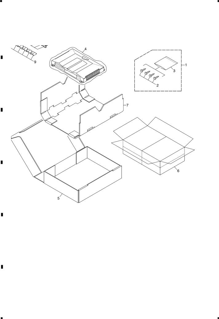
2. EXPLODED VIEWS AND PARTS LIST
2.1 PACKING
F
4 |
GM-D505/XH/EW |
1 |
|
2 |
|
3 |
|
4 |
|
|
|
||||
|
|
|

5 |
|
6 |
|
7 |
|
8 |
|
|
|
NOTE:
-Parts marked by “*” are generally unavailable because they are not in our Master Spare Parts List.
-Screws adjacent to mark on the product are used for disassembly.
-For the applying amount of lubricants or glue, follow the instructions in this manual. ( In the case of no amount instructions, apply as you think it appropriate.)
-PACKING SECTION PARTS LIST
|
|
|
|
Part No. |
|
|
|
|
GM-D505/XH/EW |
|
GM-D505/XH/ES |
Mark No. Description |
GM-D505/XR/EW |
|
GM-D505/XR/ES |
||
|
1 |
Screw Assy |
HEA0063 |
|
HEA0063 |
|
2 |
Screw |
BYC40P180FZK |
|
BYC40P180FZK |
|
3 |
Polyethylene Bag |
HEG0011 |
|
HEG0011 |
|
4 |
Polyethylene Bag |
HEG0022 |
|
HEG0022 |
|
5 |
Carton |
HHG0359 |
|
HHG0359 |
|
6 |
Contain Box |
HHL0359 |
|
HHL0359 |
|
7 |
Protector |
HHP0180 |
|
HHP0180 |
|
8-1 |
Owner’s Manual |
HRD0231 |
|
HRD0232 |
|
8-2 |
Owner’s Manual |
Not used |
|
HRD0233 |
* |
8-3 |
Warranty Card |
HRY1157 |
|
Not used |
|
9 |
Core |
HTX0003 |
|
HTX0003 |
* |
10 |
Polyethylene Bag |
HEG0025 |
|
HEG0025 |
* |
11 |
Lock Tie |
HNV0025 |
|
HNV0025 |
- Owner's Manual
Part No. |
Language |
HRD0231 |
English, Spanish, German, French, Italian, Dutch |
HRD0232 |
English, Spanish |
HRD0233 |
Arabic, Portuguese |
GM-D505/XH/EW |
5 |
|
|
A
B
C
D
E
F
5 |
|
6 |
|
7 |
|
8 |
|
|
|
||||
|
|
|
1 |
|
2 |
|
3 |
|
4 |
|
|
|
A
B
C
B |
A |
|
D
C
E
F
6 |
GM-D505/XH/EW |
1 |
|
2 |
|
3 |
|
4 |
|
|
|
||||
|
|
|

5 |
|
6 |
|
7 |
|
8 |
|
|
|
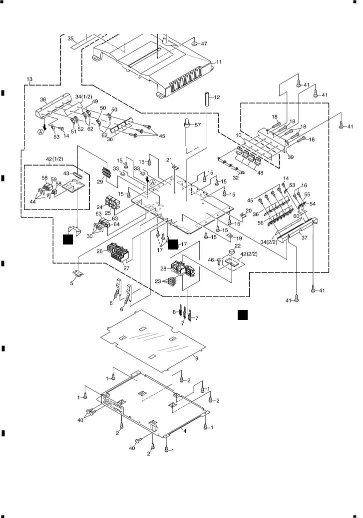
- EXTERIOR SECTION PARTS LIST
Mark No. Description |
Part No. |
|
Mark No. Description |
Part No. |
|
|
|
|
|
|
|
|
|
|
|
|
|
1 |
Screw |
BBZ30P060FMC |
|
55 Diode(D611) |
FML22S |
2 |
Screw |
BBZ30P080FMC |
|
56 FET(Q610-617) |
STP75NF75 |
3 |
Plate Unit |
HXA0395 |
|
57 LED(D910) |
DB3804X |
4 |
Case |
HNB0204 |
|
58 Variable Resistor(VR201,231) CCS1265 |
|
5 |
Lighting Conductor |
HNC0128 |
|
59 Variable Resistor(VR131) |
CCS1266 |
6 |
Lighting Conductor |
HNC0129 |
|
60 Beads Core |
HTF0003 |
7 |
Lighting Conductor |
HNC0130 |
|
* 61 Badge Unit |
HXA0380 |
8 |
Lighting Conductor |
HNC0139 |
|
62 Beads Core |
HTF0001 |
9 |
Insulator |
HNM0112 |
|
63 Variable Resistor(VR101,151) CCS1266 |
|
10 |
Insulator |
HNM0144 |
|
64 Variable Resistor(VR251) |
CCS1265 |
11 |
Heat Sink |
HNR0240 |
|
|
|
12 |
Holder |
HNV0051 |
|
|
|
13 |
Amp Unit(EW) |
HWH0213 |
|
|
|
|
Amp Unit(ES) |
HWH0214 |
|
|
|
14 |
Screw |
BBZ30P050FZK |
|
|
|
15 |
Screw |
BBZ30P060SAD |
|
|
|
16 |
Screw |
BBZ30P080FMC |
|
|
|
17 |
Screw |
BBZ30P100SAD |
|
|
|
18 |
Screw |
BSZ30P160FMC |
|
|
|
19 |
Terminal(CN605) |
CKF1059 |
|
|
|
20 |
Terminal(CN606) |
CKF1059 |
|
|
|
21 |
Terminal(CN607) |
CKF1059 |
|
|
|
22 |
Cushion |
CNM6825 |
|
|
|
23 |
Fuse(25A)(FU601-603) |
HEK0025 |
|
|
|
24 |
Pin Jack(CN801) |
HKB0022 |
|
|
|
25 |
Pin Jack(CN802) |
HKB0024 |
|
|
|
26 |
Terminal(CN804) |
HKE0045 |
|
|
|
27 |
Terminal(CN803) |
HKE0050 |
|
|
|
28 |
Terminal(CN601) |
HKE0051 |
|
|
|
29 |
Connector(CN103) |
HKS0005 |
|
|
|
30 |
Clip |
HNC0054 |
|
|
|
31 |
Holder |
HNC0143 |
|
|
|
32 |
Holder |
HNC0144 |
|
|
|
33 |
Spacer |
HNM0006 |
|
|
|
34 |
Insulator |
HNM0125 |
|
|
|
35 |
Insulator |
HNM0126 |
|
|
|
36 |
Bar |
HNR0124 |
|
|
|
37 |
Heat Sink |
HNR0201 |
|
|
|
38 |
Heat Sink |
HNR0202 |
|
|
|
39 |
Heat Sink |
HNR0203 |
|
|
|
40 |
Screw |
PPZ30P120FZK |
|
|
|
41 |
Screw |
VBZ30P110FZK |
|
|
|
42 |
Network Unit |
HWG0030 |
|
|
|
43 |
Connector(CN102) |
HKS0004 |
|
|
|
44 |
Clip |
HNC0054 |
|
|
|
45 |
Screw |
PBB30P140FMC |
|
|
|
46 |
Screw |
PPZ30P120FZK |
|
|
|
47 |
Light Pipe Unit |
HXA0383 |
|
|
|
48 |
IC(IC501,502,551,552) |
TDA7294V |
|
|
|
49 |
FET(Q401,402) |
IRF5305 |
|
|
|
50 |
FET(Q403,404) |
IRFZ44E |
|
|
|
51 |
Transistor(Q622) |
2SD2395 |
|
|
|
52 |
Transistor(Q623) |
2SB1566 |
|
|
|
53 |
Thermistor(TH601,602) |
CCX1013 |
|
|
|
54 |
Diode(D610) |
FML22R |
|
|
|
|
|
|
|
|
|
GM-D505/XH/EW |
7 |
|
|
A
B
C
D
E
F
5 |
|
6 |
|
7 |
|
8 |
|
|
|
||||
|
|
|

1 2 3 4
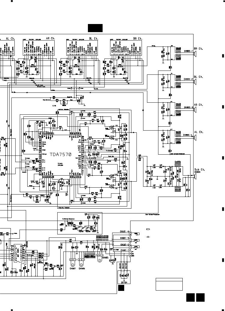
3. SCHEMATIC DIAGRAM
3.1 SCHEMATIC DIAGRAM (GUIDE PAGE)
Note: When ordering service parts, be sure to refer to " EXPLODED VIEWS AND PARTS LIST" or "ELECTRICAL PARTS LIST".
A |
A-a |
B NETWORK PCB(1/2) |
|
|
A HPF |
|
|
SWITCH |
|
A Freq |
10K(A) |
A Gain |
A Freq |
|
A Gain |
B
B Freq
20K(E)
B Freq B Freq
B Freq
C
Sub Freq
Sub Freq
D
B HPF |
Gain |
SWITCH |
B |
|
B Gain |
Sub Gain Sub Gain


 10K(A)
B NETWORKPCB(2/2)
E
F
|
|
Large size |
A-a |
A-b |
SCH diagram |
|
||
A-a |
A-b |
Guide page |
A-a |
A-b |
Detailed page |
|
BFC SWITCH |
1 |
|
|
2 |
1 |
100K(B) |
8 |
A B |
GM-D505/XH/EW |
1 |
|
2 |
|
3 |
|
4 |
|
|
|
||||
|
|
|
5 |
|
6 |
|
7 |
|
8 |
|
|
|
A-b
A |
AMP UNIT |
A |
B
22
3 |
C |
SL+
SR+
3
NOTE :
HEK0025
 >
>
HEK0025
>
HEK0025
>
Symbol indicates a resistor.
No differentiation is made between chip resistors and discrete resistors.
Symbol indicates a capacitor.
No differentiation is made between chip capacitors and discrete capacitors.
Decimal points for resistor and capacitor fixed values are expressed as :
2.2 |
← |
2R2 |
0.022 |
←R022 |
|
The > mark found on some component parts indicates the importance of the safety factor of the part. Therefore, when replacing, be sure to use parts of identical designation.
|
NETWORK UNIT |
|
|
Consists of |
|
CONNECTOR |
NETWORK PCB |
|
CONNECTOR PCB |
||
C PCB |
||
|
||
|
A C |
GM-D505/XH/EW |
9 |
|
|
D
E
F
5 |
|
6 |
|
7 |
|
8 |
|
|
|
||||
|
|
|
 Loading...