


 Loading...
ORDER NO.
CRT3566
DEH-P480MP/XU/UC
MULTI-CD CONTROL HIGH POWER CD/MP3/WMA PLAYER WITH FM/AM TUNER
DEH-P480MP/XU/UC
DEH-P4800MP/XU/UC
This service manual should be used together with the following manual(s):
Model No. |
Order No. |
Mech. Module |
Remarks |
||||||
|
|
|
|
|
|
|
|
|
|
CX-3164 |
CRT3583 |
S10.5COMP1 |
CD Mech. Module:Circuit Description, Mech. Description, Disassembly |
||||||
|
|
|
|
|
|
|
|
|
|
|
|
|
|
|
|
|
|
|
|
|
|
|
|
|
|
|
|
|
|
|
|
|
|
|
|
|
|
|
|
|
|
|
|
|
|
|
|
|
|
|
|
|
|
|
|
|
|
|
|
For details, refer to "Important Check Points for Good Servicing".
PIONEER CORPORATION 4-1, Meguro 1-chome, Meguro-ku, Tokyo 153-8654, Japan
PIONEER ELECTRONICS (USA) INC. P.O. Box 1760, Long Beach, CA 90801-1760, U.S.A. PIONEER EUROPE NV Haven 1087, Keetberglaan 1, 9120 Melsele, Belgium
PIONEER ELECTRONICS ASIACENTRE PTE. LTD. 253 Alexandra Road, #04-01, Singapore 159936
 PIONEER CORPORATION 2005
K-ZZA. NOV. 2005 Printed in Japan
1 |
2 |
3 |
4 |
SAFETY INFORMATION
CAUTION
A
|
This service manual is intended for qualified service technicians; it is not meant for the casual do-it-yourselfer. |
|
Qualified technicians have the necessary test equipment and tools, and have been trained to properly and safely repair |
|
complex products such as those covered by this manual. |
|
Improperly performed repairs can adversely affect the safety and reliability of the product and may void the warranty. |
|
If you are not qualified to perform the repair of this product properly and safely, you should not risk trying to do so |
|
and refer the repair to a qualified service technician. |
|
WARNING |
|
This product contains lead in solder and certain electrical parts contain chemicals which are known to the state of |
B |
California to cause cancer, birth defects or other reproductive harm. |
Health & Safety Code Section 25249.6 - Proposition 65 |
- CD Section Precaution
1. You should conform to the regulations governing the product (safety, radio and noise, and other regulations), and should keep the safety during servicing by following the safety instructions described in this manual.
C
2. Before disassembling the unit, be sure to turn off the power. Unplugging and plugging the connectors during power-on mode may damage the ICs inside the unit.
3.To protect the pickup unit from electrostatic discharge during servicing, take an appropriate treatment (shorting-solder) by referring to "the DISASSEMBLY".
4.After replacing the pickup unit, be sure to check the grating.
D
E
F
2 |
|
DEH-P480MP/XU/UC |
|
|
1 |
2 |
|
3 |
4 |
5 |
6 |
7 |
8 |
[Important Check Points for Good Servicing]
In this manual, procedures that must be performed during repairs are marked with the below symbol.
Please be sure to confirm and follow these procedures.
1. Product safety
Please conform to product regulations (such as safety and radiation regulations), and maintain a safe servicing environment by following the safety instructions described in this manual.
1 Use specified parts for repair.
Use genuine parts. Be sure to use important parts for safety.
2 Do not perform modifications without proper instructions.
Please follow the specified safety methods when modification(addition/change of parts) is required due to interferences such as radio/TV interference and foreign noise.
3 Make sure the soldering of repaired locations is properly performed.
When you solder while repairing, please be sure that there are no cold solder and other debris.
Soldering should be finished with the proper quantity. (Refer to the example)
4 Make sure the screws are tightly fastened.
Please be sure that all screws are fastened, and that there are no loose screws.
5 Make sure each connectors are correctly inserted.
Please be sure that all connectors are inserted, and that there are no imperfect insertion.
6 Make sure the wiring cables are set to their original state.
Please replace the wiring and cables to the original state after repairs.
In addition, be sure that there are no pinched wires, etc.
7 Make sure screws and soldering scraps do not remain inside the product.
Please check that neither solder debris nor screws remain inside the product.
8 There should be no semi-broken wires, scratches, melting, etc. on the coating of the power cord.
Damaged power cords may lead to fire accidents, so please be sure that there are no damages.
If you find a damaged power cord, please exchange it with a suitable one.
9 There should be no spark traces or similar marks on the power plug.
When spark traces or similar marks are found on the power supply plug, please check the connection and advise on secure connections and suitable usage. Please exchange the power cord if necessary.
0 Safe environment should be secured during servicing.
When you perform repairs, please pay attention to static electricity, furniture, household articles, etc. in order to prevent injuries.
Please pay attention to your surroundings and repair safely.
2. Adjustments
 To keep the original performance of the products, optimum adjustments and confirmation of characteristics within specification. Adjustments should be performed in accordance with the procedures/instructions described in this manual.
3. Lubricants, Glues, and Replacement parts
Use grease and adhesives that are equal to the specified substance.


 Make sure the proper amount is applied.
4. Cleaning
For parts that require cleaning, such as optical pickups, tape deck heads, lenses and mirrors used in projection monitors, proper cleaning should be performed to restore their performances.
5. Shipping mode and Shipping screws
To protect products from damages or failures during transit, the shipping mode should be set or the shipping screws should be installed before shipment. Please be sure to follow this method especially if it is specified in this manual.
A
B
C
D
E
F
|
|
|
|
|
|
|
|
|
|
DEH- |
P480MP/XU/UC |
|
|
3 |
|
5 |
6 |
|
|
|
7 |
8 |
|
|
|
||||||
|
1 |
2 |
3 |
4 |
|
CONTENTS |
|
|
|
|
SAFETY INFORMATION..................................................................................................................................... |
|
|
2 |
|
1. SPECIFICATIONS ............................................................................................................................................ |
|
|
5 |
A |
2. EXPLODED VIEWS AND PARTS LIST ............................................................................................................ |
|
|
7 |
2.1 PACKING |
|
|
7 |
|
|
|
|
||
|
2.2 EXTERIOR................................................................................................................................................. |
|
|
8 |
|
2.3 CD MECHANISM MODULE..................................................................................................................... |
|
|
10 |
|
3. BLOCK DIAGRAM AND SCHEMATIC DIAGRAM .......................................................................................... |
|
12 |
|
|
3.1 BLOCK DIAGRAM ................................................................................................................................... |
|
|
12 |
|
3.2 OVERALL CONNECTION DIAGRAM(GUIDE PAGE).............................................................................. |
|
14 |
|
|
3.3 KEYBOARD UNIT.................................................................................................................................... |
|
|
20 |
|
3.4 CD MECHANISM MODULE(GUIDE PAGE) ............................................................................................ |
|
22 |
|
|
4. PCB CONNECTION DIAGRAM ..................................................................................................................... |
|
|
32 |
|
4.1 TUNER AMP UNIT................................................................................................................................... |
|
|
32 |
|
4.2 KEYBOARD UNIT.................................................................................................................................... |
|
|
36 |
B |
4.3 PANEL UNIT ............................................................................................................................................ |
|
|
37 |
|
4.4 CD CORE UNIT(S10.5COMP1)............................................................................................................... |
|
|
38 |
|
5. ELECTRICAL PARTS LIST ............................................................................................................................ |
|
|
40 |
|
6. ADJUSTMENT ............................................................................................................................................... |
|
|
48 |
|
6.1 CD ADJUSTMENT................................................................................................................................... |
|
|
48 |
|
6.2 CHECKING THE GRATING AFTER CHANGING THE PICKUP UNIT .................................................... |
|
50 |
|
|
6.3 ERROR MODE ........................................................................................................................................ |
|
|
52 |
|
6.4 SYSTEM MICROCOMPUTER TEST PROGRAM ................................................................................... |
|
53 |
|
|
7. GENERAL INFORMATION............................................................................................................................. |
|
|
54 |
|
7.1 DIAGNOSIS ............................................................................................................................................. |
|
|
54 |
|
7.1.1 DISASSEMBLY ..................................................................................................................................... |
|
|
54 |
C |
7.1.2 CONNECTOR FUNCTION DESCRIPTION.......................................................................................... |
|
57 |
|
7.2 PARTS...................................................................................................................................................... |
|
|
58 |
|
|
7.2.1 IC .......................................................................................................................................................... |
|
|
58 |
|
7.2.2 DISPLAY ............................................................................................................................................... |
|
|
68 |
|
7.3 OPERATIONAL FLOW CHART ............................................................................................................... |
|
|
69 |
|
8. OPERATIONS ................................................................................................................................................ |
|
|
70 |
D
E
F
4 |
|
DEH-P480MP/XU/UC |
|
|
1 |
2 |
|
3 |
4 |
5 |
6 |
7 |
8 |
1. SPECIFICATIONS
A
B
C
D
E
F
|
|
|
|
|
|
|
|
|
|
DEH- |
P480MP/XU/UC |
|
|
5 |
|
5 |
6 |
|
|
|
7 |
8 |
|
|
|
||||||
1 |
2 |
3 |
4 |
A
B
C
D
E
F
6 |
|
DEH-P480MP/XU/UC |
|
|
1 |
2 |
|
3 |
4 |
5 |
6 |
7 |
8 |
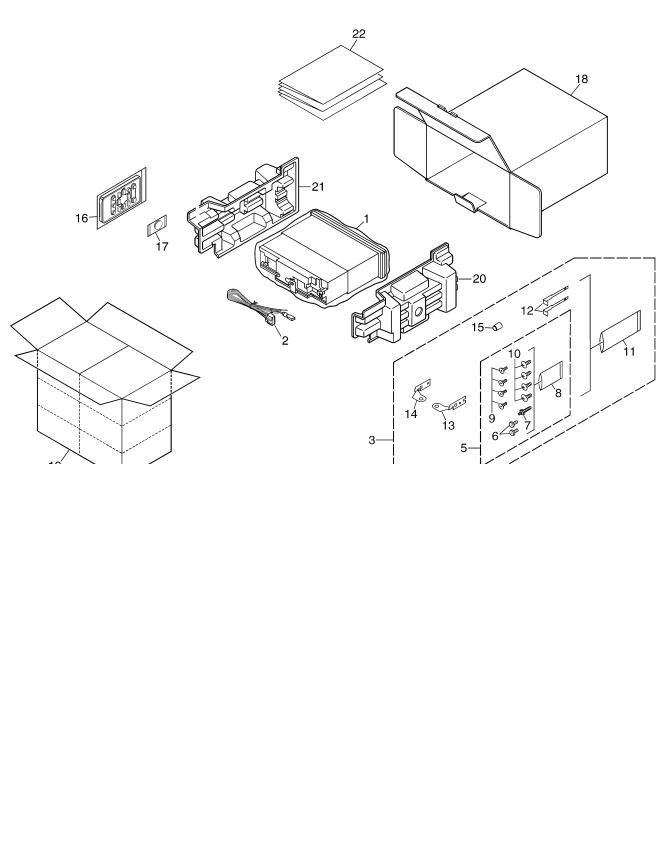
2. EXPLODED VIEWS AND PARTS LIST
NOTES : • Parts marked by " * " are generally unavailable because they are not in our Master Spare Parts List.
•The > mark found on some component parts indicates the importance of the safety factor of the part. Therefore, when replacing, be sure to use parts of identical designation.
• Screw adjacent to"mark on the product are used for disassembly.
• For the applying amount of lubricants or glue, follow the instructions in this manual. (In the case of no amount instructions,apply as you think it appropriate.)
2.1 PACKING
PACKING SECTION PARTS LIST
Mark No. |
Description |
Part No. |
|
|
1 |
Polyethylene Bag |
CEG1173 |
|
2 |
Cord Assy |
XDE7008 |
* |
3 |
Accessory Assy |
YEA5008 |
|
4 |
••••• |
|
|
5 |
Screw Assy |
YEA5007 |
|
6 |
Fixing Screw |
BPZ20P060FTB |
|
7 |
Screw |
CBA1650 |
* |
8 |
Polyethylene Bag |
CEG-127 |
|
9 |
Screw |
CRZ50P090FTC |
|
10 |
Screw |
TRZ50P080FTC |
* |
11 |
Polyethylene Bag |
CEG-158 |
|
12 |
Handle |
CNC5395 |
|
13 |
Holder |
CND1249 |
|
14 |
Holder |
CND1250 |
|
15 |
Bush |
CNV3930 |
Mark No. |
Description |
Part No. |
|
|
16 |
Remote Control Assy |
CXC5719 |
* |
17 |
Battery |
CEX1065 |
|
18 |
Carton(P480MP) |
YHG5078 |
|
|
Carton(P4800MP) |
YHG5077 |
|
19 |
Contain Box(P480MP) |
YHL5055 |
|
|
Contain Box(P4800MP) |
YHL5054 |
|
20 |
Protector |
YHP5008 |
|
21 |
Protector |
YHP5009 |
|
22-1 |
Owner's Manual(P480MP) |
YRD5038 |
|
|
Owner's Manual(P4800MP) |
YRD5037 |
|
22-2 |
Installation Manual(P480MP) |
YRD5043 |
|
|
Installation Manual(P4800MP) |
YRD5042 |
|
22-3 |
Caution Card |
CRP1310 |
* |
22-4 |
Warranty Card(P480MP) |
CRY1070 |
* |
|
Warranty Card(P4800MP) |
CRY1246 |
|
22-5 |
Caution Card(P4800MP) |
CRP1294 |
Owner's Manual,Installation Manual
Part No. |
|
Language |
|
|
|
||
|
|
|
|
|
|||
YRD5038,YRD5037,YRD5043,YRD5042 |
English, French, Spanish |
|
|
|
|||
|
|
|
|
|
|
|
|
|
|
|
|
|
|
|
|
|
|
DEH- |
P480MP/XU/UC |
|
|
7 |
|
5 |
6 |
|
|
|
7 |
8 |
|
|
|
|
|
||||
A
B
C
D
E
F
1
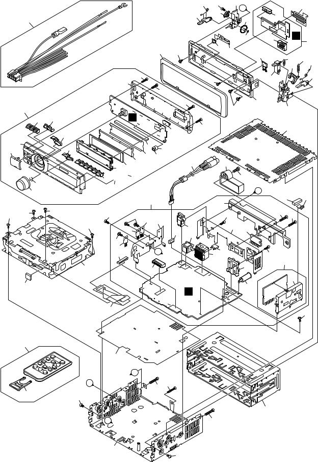
2.2 EXTERIOR
A
13
B |
|
|
|
|
|
37 |
|
|
|
45 |
46 |
|
|
|
42 |
|
57 |
56 |
43 |
|
|
||
|
|
|
|
C |
|
47 |
|
|
40 |
|
|
|
3 |
3 |
3 |
|
|
||
|
|
|
3
12
D
9
10
E
B
11
2
F
2 3 4
62 |
59 |
73 |
67 |
|
|
75 |
A |
||
69 |
76 |
79 |
||
|
||||
|
|
|
61 |
78 |
D |
|
77 |
|||
|
|
18 |
60 |
68 |
66 |
|
|
|
|
|
58 |
64 |
6563 |
|
|
|
|
||
|
|
|
|
72 |
|
38 |
|
60 |
|
71 |
70 |
48 |
|
|
|
||
|
|
|
|
||
38 |
|
|
|
|
|
B
55
51 50 44 
 39
39
41
4 20
84
20
84
28
15
14
C
A
81
|
38 |
60 |
80 |
|
|
74 |
|
|
49 |
38 |
17 |
|
|
|
|
54 |
53 |
|
|
52 |
|
|
|
82 |
|
|
|
|
16 |
87 |
|
|
|
|
86 |
C
19 |
|
36 |
|
85 31 |
|
21 |
|
34 |
35 |
|
|
27 |
83 |
||
30 |
|
|
|
|
|
|
|
B |
|
23 |
|
|
|
25 |
|
26 |
|
|
24 |
|
|
|
|
|
A |
|
29 |
|
|
|
5 5
5
2
8 7
22
22
21
32
33
1
6
8 |
|
DEH-P480MP/XU/UC |
|
|
1 |
2 |
|
3 |
4 |

|
5 |
6 |
|
7 |
8 |
EXTERIOR SECTION PARTS LIST |
|
|
|
|
|
Mark No. |
Description |
Part No. |
Mark No. |
Description |
Part No. |
1 |
Screw |
ASZ26P050FTC |
46 |
Button(CLOCK,DISPLAY)(P480MP) |
YAC5098 |
2 |
Screw |
BMZ30P040FTB |
|
Button(CLOCK,DISPLAY)(P4800MP) |
YAC5073 |
3 |
Screw |
BSZ26P060FTC |
|
|
|
4 |
Screw |
BSZ30P060FTC |
47 |
Spring |
YBH5003 |
5 |
Screw |
BSZ30P200FTC |
48 |
Cover |
YNS5113 |
|
|
|
49 |
Connector(CN1801) |
CKS5207 |
6 |
Holder |
CNC8659 |
50 |
LCD(LCD1801) |
YAW5051 |
7 |
Earth Plate |
CNC8915 |
51 |
Holder |
YNC5013 |
8 |
Cushion |
CNM8890 |
|
|
|
9 |
Insulator |
CNM7682 |
52 |
Sheet |
YNM5015 |
10 |
Remote Control Assy |
CXC5719 |
53 |
Spacer |
YNM5016 |
|
|
|
54 |
Connector |
YNV5030 |
11 |
Cover |
CNS7068 |
55 |
Lighting Conductor |
YNV5032 |
12 |
CD Mechanism Module(S10.5) |
CXK5750 |
56 |
Grille Unit(P480MP) |
YXA5159 |
13 |
Cord Assy |
XDE7008 |
|
Grille Unit(P4800MP) |
YXA5127 |
14 |
Insulator |
XNM7100 |
|
|
|
15 |
Cable |
YDE5013 |
57 |
Button Unit(UP,DOWN,LEFT,RIGHT)(P480MP) |
YXC5025 |
|
|
|
|
Button Unit(UP,DOWN,LEFT,RIGHT)(P4800MP) |
YXC5022 |
16 |
Cord Assy |
YDE5014 |
58 |
Button(EJECT) |
CAC7752 |
17 |
Case |
YNB5008 |
59 |
Screw(M2 x 4) |
CBA1649 |
18 |
Panel(P480MP) |
YNS5157 |
60 |
Screw(M2 x 4.5) |
CBA1925 |
|
Panel(P4800MP) |
YNS5114 |
|
|
|
19 |
Tuner Amp Unit(P480MP) |
YWM5085 |
61 |
Washer |
CBF1038 |
|
Tuner Amp Unit(P4800MP) |
YWM5087 |
62 |
Spring |
CBH2650 |
|
|
|
63 |
Spring |
CBH2651 |
20 |
Screw |
ASZ26P060FTC |
64 |
Spring |
CBH2652 |
21 |
Screw |
BPZ26P080FTC |
65 |
Spring |
CBH2653 |
22 |
Screw |
BSZ26P160FTC |
|
|
|
> 23 |
Fuse(10 A) |
CEK1208 |
66 |
Spring |
CBL1512 |
24 |
Pin Jack(CN353) |
CKB1051 |
67 |
Holder |
CND1254 |
|
|
|
68 |
Pin |
CNV6486 |
25 |
Plug(CN901) |
CKM1376 |
69 |
Arm |
CNV7400 |
26 |
Plug(CN801) |
CKS3537 |
70 |
Arm |
CNV7401 |
27 |
Connector(CN352) |
CKS3584 |
|
|
|
28 |
Connector(CN701) |
CKS3834 |
71 |
Arm |
CNV7402 |
29 |
Antenna Jack(CN401) |
CKX1056 |
72 |
Arm |
CNV7403 |
|
|
|
73 |
Holder Unit |
CXB9501 |
30 |
Connector(CN101) |
CKS5271 |
74 |
Holder Unit |
CXB9502 |
31 |
Holder |
CND1352 |
75 |
Damper Unit |
CXB9503 |
32 |
FM/AM Tuner Unit |
CWE1957 |
|
|
|
33 |
Holder |
CND1054 |
76 |
Gear |
YNV5053 |
34 |
JACK(CN621) |
YKS5001 |
77 |
Panel Unit |
YWM5099 |
|
|
|
78 |
Connector(CN1901) |
CKS4806 |
35 |
Holder |
YNC5015 |
79 |
Connector(CN1902) |
CKS5192 |
36 |
Heat Sink |
YNR5004 |
80 |
Sub Panel Unit |
YXA5160 |
37 |
Detachable Assy(P480MP) |
YXA5104 |
|
|
|
|
Detachable Assy(P4800MP) |
YXA5105 |
81 |
Chassis Unit |
YXA5131 |
38 |
Screw |
BPZ20P100FTB |
82 |
IC(IC1801) |
TSOP4840SB1 |
|
|
|
83 |
IC(IC301) |
PAL007B |
39 |
Spring |
CBH2210 |
84 |
Transistor(Q702,Q911) |
2SD2396 |
40 |
Knob(SOURCE,VOLUME) |
YAA5006 |
85 |
IC(IC921) |
NJM2388F84 |
41 |
Button(OPEN) |
YAC5067 |
|
|
|
42 |
Button(EQ) |
YAC5068 |
86 |
Screw(P4800MP) |
BMZ40P140FTC |
43 |
Button(BAND) |
YAC5069 |
87 |
Holder(P4800MP) |
CNV7619 |
44 |
Button(1-6) |
YAC5070 |
|
|
|
45Button(AUDIO,FUNCTION,SW)(P480MP) YAC5096 Button(AUDIO,FUNCTION,SW)(P4800MP) YAC5072
|
|
|
|
|
|
|
|
|
|
DEH- |
P480MP/XU/UC |
|
|
9 |
|
5 |
6 |
|
|
|
7 |
8 |
|
|
|
||||||
A
B
C
D
E
F
1 |
2 |
3 |
4 |
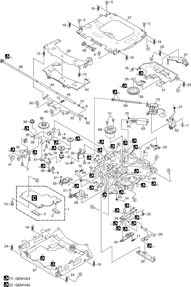
2.3 CD MECHANISM MODULE
A
B
C
D
E
F
10 |
|
DEH-P480MP/XU/UC |
|
|
1 |
2 |
|
3 |
4 |
|
5 |
6 |
|
|
|
|
7 |
8 |
|
|
CD MECHANISM MODULE SECTION PARTS LIST |
|
|
|
|
||||||
Mark No. |
Description |
Part No. |
|
Mark No. |
|
Description |
Part No. |
|
||
1 |
CD Core Unit(S10.5COMP1) |
CWX3176 |
50 |
Rack |
CNV8342 |
|
||||
2 |
Connector(CN101) |
CKS4808 |
|
|
|
|
|
|
|
|
3 |
Connector(CN901) |
CKS5284 |
51 |
Roller |
CNV8343 |
|
||||
4 |
Screw |
BMZ20P025FTC |
52 |
Holder |
CNV8344 |
|
||||
5 |
Screw |
BSZ20P040FTC |
53 |
Arm |
CNV8345 |
|
||||
|
|
|
|
54 |
Guide |
CNV8347 |
|
|||
6 |
Screw(M2 x 3) |
CBA1511 |
55 |
Arm |
CNV8348 |
|
||||
7 |
Screw(M2 x 4) |
CBA1835 |
|
|
|
|
|
|
|
|
8 |
Washer |
CBF1038 |
56 |
Arm |
CNV8349 |
|
||||
9 |
••••• |
|
|
57 |
Arm |
CNV8350 |
|
|||
10 |
Spring |
CBH2609 |
58 |
Clamper |
CNV8365 |
|
||||
|
|
|
|
59 |
Arm |
CNV8386 |
|
|||
11 |
Spring |
CBH2612 |
60 |
Guide |
CNV8396 |
|
||||
12 |
Spring |
CBH2614 |
|
|
|
|
|
|
|
|
13 |
Spring |
CBH2616 |
61 |
Arm |
CNV8413 |
|
||||
14 |
Spring |
CBH2617 |
62 |
Collar |
CNV8447 |
|
||||
15 |
Spring |
CBH2620 |
63 |
Motor Unit(M2) |
CXC4026 |
|
||||
|
|
|
|
64 |
Arm Unit |
CXC4027 |
|
|||
16 |
Spring |
CBH2855 |
65 |
Chassis Unit |
CXC4028 |
|
||||
17 |
Spring |
CBH2937 |
|
|
|
|
|
|
|
|
18 |
Spring |
CBH2735 |
66 |
Gear Unit |
CXC4029 |
|
||||
19 |
Spring |
CBH2854 |
67 |
Frame Unit |
CXC4031 |
|
||||
20 |
Spring |
CBH2642 |
68 |
Motor Unit(M1) |
CXC6742 |
|
||||
|
|
|
|
69 |
Screw Unit |
CXC6359 |
|
|||
21 |
Spring |
CBH2856 |
70 |
Screw |
JFZ20P020FTC |
|
||||
22 |
Spring |
CBH2857 |
|
|
|
|
|
|
|
|
23 |
Spring |
CBH2860 |
71 |
Screw |
JGZ17P022FTC |
|
||||
24 |
Spring |
CBH2861 |
72 |
Washer |
YE20FTC |
|
||||
25 |
Spring |
CBL1686 |
73 |
Pickup Unit(P10.5)(Service) |
CXX1942 |
|
||||
|
|
|
|
74 |
Screw |
IMS26P030FTC |
|
|||
26 |
Arm |
CND1909 |
|
|
|
|
|
|
|
|
27 |
Frame |
CND2582 |
|
|
|
|
|
|
|
|
28 |
Bracket |
CND2583 |
|
|
|
|
|
|
|
|
29 |
Arm |
CND2584 |
|
|
|
|
|
|
|
|
30 |
Lever |
CND2585 |
|
|
|
|
|
|
|
|
31 |
Arm |
CND2586 |
|
|
|
|
|
|
|
|
32 |
Bracket |
CND2587 |
|
|
|
|
|
|
|
|
33 |
Arm |
CND2588 |
|
|
|
|
|
|
|
|
34 |
Lever |
CND2589 |
|
|
|
|
|
|
|
|
35 |
Holder |
CNV7201 |
|
|
|
|
|
|
|
|
36 |
Gear |
CNV7207 |
|
|
|
|
|
|
|
|
37 |
Gear |
CNV7208 |
|
|
|
|
|
|
|
|
38 |
Gear |
CNV7209 |
|
|
|
|
|
|
|
|
39 |
Gear |
CNV7210 |
|
|
|
|
|
|
|
|
40 |
Gear |
CNV7211 |
|
|
|
|
|
|
|
|
41 |
Gear |
CNV7212 |
|
|
|
|
|
|
|
|
42 |
Rack |
CNV7214 |
|
|
|
|
|
|
|
|
43 |
Arm |
CNV7216 |
|
|
|
|
|
|
|
|
44 |
Roller |
CNV8189 |
|
|
|
|
|
|
|
|
45 |
Gear |
CNV7219 |
|
|
|
|
|
|
|
|
46 |
Guide |
CNV7361 |
|
|
|
|
|
|
|
|
47 |
Gear |
CNV7595 |
|
|
|
|
|
|
|
|
48 |
Guide |
CNV8448 |
|
|
|
|
|
|
|
|
49 |
Arm |
CNV7805 |
|
|
|
|
|
|
|
|
|
|
|
|
|
|
|
|
|
|
|
|
|
|
|
DEH- |
P480MP/XU/UC |
|
|
|
11 |
|
|
5 |
6 |
|
|
|
|
|
7 |
8 |
|
|
|
|
|
|
|
|||||
A
B
C
D
E
F
1 |
2 |
3 |
4 |
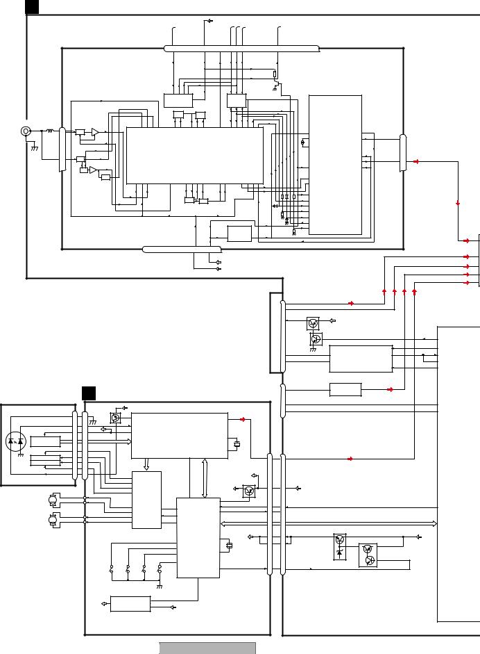
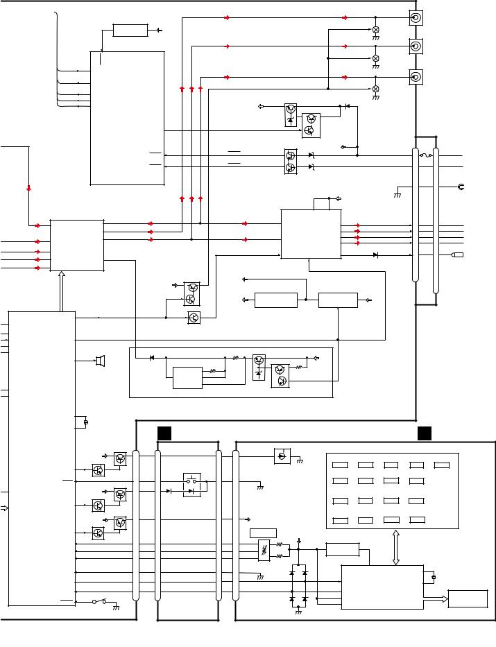
3. BLOCK DIAGRAM AND SCHEMATIC DIAGRAM
3.1 BLOCK DIAGRAM
A |
|
A TUNER AMP UNIT |
|
|
|
|
|
|
|
|
|
|
|
|
|
|
|
|
|
|
|
|
|
|
|
|
|
|
|
|
|||||
|
|
|
|
|
|
|
|
|
|
|
|
|
|
|
|
|
|
|
|
|
|
|
|
|
|
|
|
|
|
||||||
|
|
|
|
|
|
|
|
|
|
|
|
|
|
|
|
|
|
VDD5 |
|
|
|
|
|
|
|
|
|
|
|
|
|
|
|
|
|
|
|
|
|
|
|
|
|
|
|
|
|
|
|
|
|
|
|
|
|
TUNPDI TUNPCK |
|
|
|
TUNPDO |
|
|
|
|
|
|
|
|
|
|
|
|
|
|
|
FM/AM TUNER UNIT |
|
|
7 |
6 |
|
|
13 |
|
5 |
10 |
9 |
8 |
11 |
|
14 |
18 |
19 |
20 |
21 |
|
|
|
|
|
|
||||||
|
|
|
|
|
|
NC |
CE2 |
|
|
VDD |
|
SL |
DI |
CK |
CE1 |
NC |
|
DO |
NC |
NC |
NC |
NC |
|
|
|
|
|
|
|||||||
|
|
|
|
|
|
|
|
|
|
|
|
|
|
|
|
|
|
|
|
|
|
|
|||||||||||||
|
|
|
|
|
|
|
|
|
|
|
|
|
|
|
|
|
ROM_ |
|
|
|
|
|
|
|
|
|
|
|
|
|
|
|
|
|
|
|
|
|
|
|
|
|
|
|
|
|
|
|
IC 3 EEPROM |
|
|
|
|
IC 5 |
|
|
|
|
|
|
|
|
|
|
|
|
|
|
|||
|
|
|
|
|
|
|
|
|
|
|
|
|
|
5.0V |
|
|
|
|
5V |
← 3.3V |
|
|
|
|
|
|
|
|
|
|
|
|
|
||
|
|
|
|
|
|
|
|
|
|
|
|
|
|
OSC |
|
LPF |
|
|
|
|
|
|
|
|
|
|
|
|
|
|
|
|
|
|
|
B |
ANTENNA |
CN401 |
|
AM ANT |
FMRF |
|
|
|
|
|
|
|
|
|
|
|
|
|
|
|
|
|
|
|
|
|
|
|
|
|
|
|
|||
|
|
1 |
|
|
|
|
|
|
|
|
|
|
|
|
|
|
|
|
|
|
|
|
|
|
|
|
|
|
|
|
|||||
|
|
|
1 |
ATT |
|
|
|
|
|
|
|
|
|
|
|
|
|
|
|
|
|
|
|
|
|
|
|
|
|
|
|
||||
|
|
|
|
|
|
|
|
|
|
|
|
|
|
|
|
|
|
|
|
|
|
|
|
|
|
|
|
|
|
|
|
|
|||
|
|
2 |
|
|
|
|
|
|
|
|
|
|
|
|
|
|
|
|
|
|
|
|
|
|
|
|
|
|
|
|
|
Rch 24 |
|
|
|
|
|
|
|
|
|
|
|
|
|
|
|
|
|
|
|
|
|
|
|
|
|
|
|
|
|
|
|
|
|
IC 2 |
|
|
|
|
|
|
|
|
|
FM ANT |
|
|
|
|
|
|
|
|
IC 1 |
|
|
|
|
|
|
|
|
|
|
|
|
|
|
2.5V |
|
|
|
|
|
||
|
|
|
|
|
|
|
|
|
|
|
|
|
|
|
|
|
|
|
|
|
|
|
|
|
|
|
|
|
|
|
|
||||
|
|
|
|
|
|
|
|
|
|
|
|
3.3V |
|
|
|
|
|
|
|
|
|
|
|
|
|
|
|
|
|
|
|
||||
|
|
|
|
3 |
|
ATT |
|
|
|
|
|
|
|
|
|
|
|
|
|
|
|
|
|
|
|
|
|
|
|
Lch 23 |
|
|
|
||
|
|
|
|
|
FMRF |
|
|
|
|
|
|
MIXER, IF AMP |
|
|
|
|
|
|
|
|
|
|
|
|
|
|
|
|
|
||||||
|
|
|
|
|
|
|
|
|
|
|
|
|
|
|
|
|
|
|
|
|
|
|
|
DET, FM MPX |
|
|
|
|
|
||||||
|
|
|
|
|
|
|
|
|
|
|
|
|
|
|
|
|
|
|
|
|
|
|
|
|
|
|
|
|
|
|
|
|
|
||
|
|
|
|
|
|
ANT adj |
RF adj |
|
|
|
|
|
|
|
|
|
|
|
|
|
|
|
|
|
|
|
|
|
|
|
|
|
|
|
|
|
|
|
|
|
|
|
|
|
|
|
|
|
|
|
|
|
|
|
|
|
|
|
|
|
|
|
|
|
|
|
|
|
|
||
|
|
|
|
|
|
|
|
|
|
|
|
|
|
|
T51 |
CF52 |
|
|
|
|
|
|
|
|
|
|
|
|
|
|
|
|
|
|
|
|
|
|
|
|
|
|
|
|
|
|
|
|
|
|
|
|
|
|
|
|
|
|
|
|
|
|
|
|
|
|
|
|
|
|
|
|
|
|
|
|
|
|
|
|
|
|
RFGND |
OSCGND |
|
AUDIOGND |
|
|
VDD 3.3 |
|
|
|
IC 4 |
|
|
|
|
|
|
|
|
|
|
|
|
|
|
|
|
|
|
|
|
|
|
|
|
|
DGND |
|
VCC |
|
3.3V |
3.3V← |
2.5V |
2.5V |
|
|
|
|
|
|
|
|
|
|
TUNL |
2 |
|||||
C |
|
|
|
|
|
|
|
|
|
|
NC |
|
|
|
|
|
|
|
|
|
|
|
|
|
|
|
|
|
|||||||
|
|
|
|
|
|
|
|
|
|
|
|
|
|
|
|
|
|
|
|
|
|
|
|
|
|
|
|
||||||||
|
|
|
|
|
|
|
|
|
|
|
|
|
|
|
|
|
|
|
|
|
|
|
|
|
|
|
|
|
|
|
|
|
|
|
|
|
|
|
|
|
|
|
|
|
|
|
2 |
12 |
15 |
22 |
16 |
4 |
17 |
|
|
|
|
|
|
|
|
|
|
|
|
|
|
|
|
|
|
|
|
|
|
|
|
|
|
|
|
|
|
|
|
|
|
|
|
|
|
|
|
|
|
|
|
|
|
|
|
|
|
|
|
|
5 |
|
|
|
|
|
|
|
|
|
|
|
|
|
|
|
|
|
|
|
VDD_3.3V |
|
|
|
|
|
|
|
|
|
|
|
|
|
4 |
||
|
|
|
|
|
|
|
|
|
|
|
|
|
|
|
|
|
|
|
|
|
|
|
|
|
|
|
|
|
|
|
|
|
|
|
|
|
|
|
|
|
|
|
|
|
|
|
|
|
|
|
|
|
|
|
VCC8 |
|
|
|
|
|
|
|
|
|
|
|
|
|
|
3 |
|
|
|
|
|
|
|
|
|
|
|
|
|
|
|
|
|
|
|
|
|
|
|
|
|
|
|
|
|
|
|
|
|
|
|
|
|
|
|
|
|
|
|
|
|
|
|
|
|
|
|
|
|
|
|
|
|
|
|
|
|
|
|
|
|
|
|
|
|
|
|
|
1 |
|
|
|
|
|
|
|
|
|
|
|
|
|
|
|
|
|
|
|
|
|
|
|
|
|
|
CN101 |
|
|
|
|
|
|
|
||
|
|
|
|
|
|
|
|
|
|
|
|
|
|
|
|
|
|
|
|
|
|
|
|
|
11 |
BUSL− |
|
|
|
|
|
|
|
|
|
|
|
|
|
|
|
|
|
|
|
|
|
|
|
|
|
|
|
|
|
|
|
|
|
|
|
|
|
|
|
|
|
|
|
|
|
|
|
|
|
|
|
|
|
|
|
|
|
|
|
|
|
|
|
|
|
|
|
|
|
|
7 |
BUSL+ |
|
|
|
|
|
|
|
|
|
|
|
|
|
|
|
|
|
|
|
|
|
|
|
|
|
|
|
|
|
|
|
|
|
|
|
B14 |
|
Q101 |
|
|
|
|
|
|
|
|
|
|
|
|
|
|
|
|
|
|
|
|
|
|
|
|
|
|
|
|
|
|
|
|
8 |
|
|
B.UP |
|
|
|
|
|
||
|
|
|
|
|
|
|
|
|
|
|
|
|
|
|
|
|
|
|
|
|
|
|
|
|
|
|
|
|
|
|
|
|
|
||
|
|
|
|
|
|
|
|
|
|
|
|
|
|
|
|
|
|
|
|
|
|
|
|
|
BUS |
|
|
|
Q102 |
|
|
|
|
|
|
|
|
|
|
|
|
|
|
|
|
|
|
|
|
|
|
|
|
|
|
|
|
|
|
|
_ |
|
|
|
|
ASENBO |
|
|
40 |
|
|
|
|
|
|
|
|
|
|
|
|
|
|
|
|
|
|
|
|
|
|
|
|
|
|
|
IP |
|
|
|
|
|
|
ASENBO |
|
||
|
|
|
|
|
|
|
|
|
|
|
|
|
|
|
|
|
|
|
|
|
|
|
|
|
|
|
|
|
|
|
|
|
|
||
|
|
|
|
|
|
|
|
|
|
|
|
|
|
|
|
|
|
|
|
|
|
|
|
|
|
|
|
|
|
|
|
1 |
30 |
TX |
|
|
|
|
|
|
|
|
|
|
|
|
|
|
|
|
|
|
|
|
|
|
|
|
|
|
|
|
|
|
|
|
|
|
29 |
|
|
|
|
|
|
|
|
|
|
|
|
|
|
|
|
|
|
|
|
|
|
|
|
|
|
|
5 |
B− |
|
|
5 |
IC 101 |
2 |
RX |
|
||
D |
|
|
|
|
|
|
|
|
|
|
|
|
|
|
|
|
|
|
|
|
|
|
|
|
1 |
B+ |
|
|
6 |
HA12241FP |
|
27 |
RX2 |
|
|
|
|
|
|
|
|
|
|
|
|
|
|
|
|
|
|
|
|
|
|
|
|
|
|
|
|
|
|
|
|
|
|
|
|||
|
|
|
|
|
|
|
|
|
|
|
|
|
|
|
|
|
|
|
|
|
|
|
|
|
|
|
|
|
|
|
8 |
52 |
IPPW |
|
|
|
|
|
|
|
|
|
|
|
|
|
|
|
|
|
|
|
|
|
|
|
|
|
|
|
|
|
|
|
|
|
|
|
|||
|
|
|
|
|
|
|
|
|
|
|
|
|
|
|
|
|
|
|
|
|
|
|
|
|
|
|
|
|
|
|
|
|
|
|
|
|
|
|
|
|
|
|
|
|
|
|
|
|
|
|
|
|
|
|
|
|
|
|
|
|
|
CN621 |
|
|
|
|
|
|
|
||
|
PICKUP UNIT |
|
|
CD CD CORE UNIT(S10.5COMP1) |
|
|
|
|
|
|
|
|
5 |
AUX-L |
|
3 |
IC 751 |
1 |
|
|
SYSTEM CONT |
||||||||||||||
|
|
|
|
|
|
|
|
|
|
|
|
|
|
|
|||||||||||||||||||||
|
(P10.5)(SERVICE) |
|
|
|
|
|
|
|
|
|
|
|
|
|
|
NJM4558MD |
|
|
|
|
|
||||||||||||||
|
|
|
|
|
|
|
|
|
|
|
|
|
|
|
|
|
|
|
IC 601(2/2 |
||||||||||||||||
|
|
|
|
|
|
|
|
|
|
|
|
|
|
|
|
|
|
|
|
|
|
|
|
|
3 |
KEY1 |
|
|
|
|
|
34 |
PEG155B |
||
|
|
|
|
|
|
|
|
|
|
|
|
|
|
|
|
|
|
|
|
|
|
|
|
|
|
|
|
|
|
KEYD |
|
||||
|
|
|
|
|
|
|
CN101 |
V3R3D |
|
|
|
|
|
|
|
|
|
|
|
|
|
|
|
|
|
|
|
|
|
|
|
||||
|
LASER |
|
|
|
|
|
|
|
|
|
|
|
|
|
|
|
|
|
|
|
2 |
KEY2 |
|
|
|
|
|
94 |
KEYAD |
|
|||||
|
|
|
|
|
|
|
|
|
|
|
|
|
|
|
|
|
|
|
|
|
|
|
|
|
|
|
|
||||||||
|
DIODE |
|
|
LD- |
|
|
|
|
142 |
|
|
|
|
|
|
|
|
|
|
|
|
|
|
|
|
|
|
|
|
|
|
|
|
||
|
|
|
15 |
15 |
|
|
LD |
|
|
|
|
|
|
|
|
|
31 |
|
|
|
|
|
|
|
|
|
|
|
|
|
|
|
|||
|
|
|
|
|
|
|
|
|
IC201 |
|
|
LOUT |
|
|
|
|
|
|
|
|
|
|
|
|
|
|
|
||||||||
|
|
|
|
|
|
|
|
Q101 |
|
|
|
|
|
|
|
|
|
|
|
|
|
|
|
|
|
|
|
|
|
|
|
||||
|
|
|
|
MD |
5 |
5 |
|
143 |
PD |
|
UPD63763CGJ |
|
|
|
|
|
|
|
|
|
|
|
|
|
|
|
|
|
|
|
|||||
|
|
|
|
|
|
|
|
|
|
|
|
|
|
|
|
|
|
|
|
|
|
|
|
|
|
||||||||||
|
|
|
|
|
REFO |
|
|
|
|
|
|
|
|
|
|
|
|
|
|
|
|
|
|
|
|
|
|||||||||
|
|
|
|
VREF |
8 |
8 |
|
133 |
REFOUT |
RF-AMP,CD DECODER, |
|
|
|
|
|
|
|
|
|
|
|
|
|
|
|
|
|
|
|||||||
|
|
|
|
AC,BD |
|
|
34 |
|
|
|
|
|
|
|
|
|
|
|
|
|
|
|
|||||||||||||
|
|
HOLOGRAM |
|
|
|
|
|
|
MP3 , WMA, DECODER, |
XTAL |
|
|
|
|
|
|
|
|
|
|
|
|
|
|
|
||||||||||
|
|
UNIT |
|
|
|
|
|
F,E |
|
DIGITAL SERVO / DATA PROCESSOR |
|
|
|
|
|
|
|
|
|
|
|
|
|
|
|
|
|||||||||
|
|
|
|
FOM |
|
|
FOM |
|
|
|
|
|
|
|
|
|
/XTAL 35 |
|
|
CN901 |
|
|
|
|
|
|
|
|
|
|
|
||||
|
|
|
|
3 |
3 |
|
|
|
|
|
|
|
|
|
|
|
|
|
CN701 |
|
|
|
|
|
|
|
|||||||||
|
|
|
|
FOP |
|
|
FOP |
|
|
|
|
|
|
|
LOCK/RFOK |
|
|
X201 |
|
LOUT |
|
|
LOUT |
|
|
|
|
|
|
|
|
||||
|
|
FOCUS ACT. |
2 |
2 |
|
|
|
|
|
|
|
|
|
16.93MHz |
16 |
16 |
|
|
|
|
|
|
|
|
|||||||||||
|
MONITOR TRACKING ACT. |
TOP |
1 |
1 |
TOP |
|
|
|
|
|
|
|
|
56 |
|
|
|
|
|
|
|
|
|
|
|
|
|
|
|
|
|
|
|
||
|
DIODE |
|
|
TOM |
|
|
TOM |
|
|
TD,FD |
|
SD,MD |
|
|
|
|
XRST,XASTB,ADO,XCK, |
|
|
|
|
|
|
|
|
|
|
|
|
|
|||||
|
|
|
|
4 |
4 |
|
|
|
|
|
|
|
|
|
|
|
|
|
|
|
|
|
|
|
|
|
|
||||||||
|
|
|
|
LD+ |
14 |
14 |
|
|
|
|
CD |
|
|
|
|
XSO,XSI,WAIT,XINT |
|
|
|
|
|
|
|
|
|
|
|
|
|
||||||
|
|
|
|
|
|
12 |
|
|
|
|
|
|
|
|
|
|
VDD |
|
|
|
|
|
|
|
|
|
|
|
|
|
|||||
E |
|
|
|
|
|
|
|
|
|
|
|
|
|
|
|
|
|
|
|
|
|
|
|
|
|
|
|
|
|
|
|
||||
|
|
|
|
|
|
|
|
11 |
FOPFOM DRIVER |
|
|
|
|
|
|
|
|
|
Q701 |
|
|
|
|
|
|
|
|
|
|
|
|
||||
|
|
|
|
|
|
|
|
|
14 |
TOP |
|
|
|
|
|
|
|
|
SWVDD |
|
|
VDD 11 |
11 |
|
|
VDD5 |
|
|
|
|
|
|
|||
|
|
|
|
|
|
|
|
|
13 |
TOM |
|
|
|
|
|
63 |
|
|
|
|
|
|
|
|
|
|
|
|
|
|
|
|
|
|
|
|
|
SPINDLE |
M |
|
|
|
|
|
|
IC301 |
|
|
|
|
|
|
|
|
|
|
|
|
|
|
|
|
|
|
|
|
|
|
|||
|
|
|
|
|
|
|
|
|
|
LOCK |
/CD3VON |
43 |
|
|
|
|
|
|
|
|
|
|
|
|
|
|
|
|
|||||||
|
|
MOTOR |
|
|
|
|
|
|
16 |
BA5835FP |
21 |
|
|
|
|
|
14 |
|
|
|
/RESET 10 |
|
/RESET |
|
|
|
|
|
21 |
|
|
||||
|
|
|
|
|
|
|
|
|
SOP |
CLCONT |
41 |
CLCONT |
RESET |
|
|
|
10 |
|
|
|
|
|
CDRST |
|
|||||||||||
|
|
|
|
|
|
|
|
|
15 |
SOM |
|
|
22 |
40 |
CDMUTE 39 |
|
|
|
CDMUTE 8 |
8 |
|
|
|
|
|
|
|
|
|
|
|||||
|
LOAD/ CARRIAGE |
M |
|
|
|
|
|
18 |
LCOP |
|
LOEJ |
LOEJ |
IC701 |
|
|
BRST,BRXEN,BSRQ |
|
|
BRST,BRXEN,BSRQ,BDATA,BSCK |
|
|
|
|
|
|||||||||||
|
|
MOTOR |
|
|
|
|
|
17 |
LCOM |
|
CONT |
9 |
47 |
CONT |
|
|
|
|
|
|
|
|
|
||||||||||||
|
|
|
|
|
|
|
|
|
|
|
|
|
|
|
PE5505A |
|
|
BDATA,BSCK |
|
|
|
|
|
|
|
|
|
|
|
|
|||||
|
|
|
|
|
|
|
|
|
|
|
|
|
|
|
CD CONTROLLER |
|
|
|
|
|
|
Q702 |
|
|
|
|
|
||||||||
|
|
|
|
|
|
|
|
|
|
|
|
|
|
|
|
|
|
VD |
|
|
VD |
|
|
|
|
|
|
|
|
||||||
|
|
|
|
|
|
|
|
|
|
|
|
|
|
|
|
|
|
|
12 |
|
|
VD |
1 |
1 |
|
|
|
|
|
|
B.UP |
|
|
||
|
|
|
|
|
|
|
|
|
|
|
|
|
|
32 |
|
|
|
X1 |
|
|
|
|
|
|
|
|
Q701 |
|
|
|
|||||
|
|
|
|
|
|
|
|
|
|
|
|
|
|
12EJ |
|
|
|
|
X701 |
|
|
2 |
2 |
|
|
|
|
3 |
4 |
|
|
|
|||
|
|
|
|
|
|
|
|
|
|
|
|
|
|
31 |
|
|
|
|
|
|
|
|
|
|
|
|
|
|
|||||||
|
|
|
|
|
|
|
|
|
|
|
|
|
|
8EJ |
|
|
|
13 |
4.00MHz |
|
|
|
|
|
|
|
|
|
5 |
|
|
|
|||
|
|
|
|
|
|
|
|
|
|
|
|
|
|
30 |
|
|
X2 |
|
|
|
|
|
|
|
|
|
|
|
|
||||||
|
|
|
|
|
|
|
|
|
|
|
|
|
|
|
|
|
|
|
|
|
|
|
|
|
|
|
|
|
|
|
|||||
|
|
|
|
|
|
|
|
|
|
|
|
|
|
|
DSCSNS |
|
|
|
|
|
|
|
|
|
|
|
|
|
|
|
2 |
|
|
|
|
|
|
|
|
|
|
|
|
|
|
|
|
|
|
42 |
|
|
|
|
|
|
|
|
|
|
|
|
|
|
|
|
|
|
|
|
|
|
|
|
|
|
|
|
|
|
|
|
|
|
|
HOME |
|
|
|
|
|
|
|
|
|
|
|
|
|
|
|
|
|
|
|
|
|
|
|
|
|
|
|
|
|
|
|
|
|
|
|
|
|
|
|
49 |
|
|
|
VDCONT |
|
|
|
|
|
|
|
|
|
|
|
|
|
|
|
|
|
|
|
|
S904 |
S905 |
|
|
|
S901 |
|
|
VDCONT |
|
|
|
9 |
9 |
VDCONT |
|
|
|
|
|
|
|
|||||||
|
|
|
|
|
|
|
12EJ |
8EJ |
|
|
|
HOME |
|
|
|
|
|
|
|
|
|
|
|
|
|
|
|
|
|
||||||
|
|
|
|
|
|
|
|
|
|
|
CD3VON |
|
|
|
|
|
|
|
|
|
|
|
|
|
|
|
|
|
|
||||||
|
|
|
|
|
|
|
|
|
|
|
|
|
|
|
|
|
|
|
|
|
|
|
|
|
|
|
|
|
|
|
|
|
|
||
|
|
|
|
|
|
|
|
|
|
S903 |
|
|
|
|
46 |
|
|
|
|
|
|
|
|
|
|
|
|
|
|
|
|
|
|
|
|
|
|
|
|
|
|
|
|
|
|
|
|
|
|
|
|
|
|
|
|
|
|
|
|
|
|
|
|
|
|
|
|
|
|
||
|
|
|
|
|
|
|
|
|
|
DSCSNS |
|
|
|
|
|
|
|
|
|
|
|
|
|
|
|
|
|
|
|
|
|
|
|
||
F |
|
|
|
|
|
|
|
4 |
IC203 |
|
1 |
|
|
|
|
|
|
|
|
|
|
|
|
|
|
|
|
|
|
|
|
|
|
|
|
|
|
|
|
|
|
V3R3D |
|
|
|
|
|
|
|
|
|
|
|
|
|
|
|
|
|
|
|
|
|
|
|
|
|
||||
|
|
|
|
|
|
|
|
|
NJM2886DL3-33 3 |
|
VD |
|
|
|
|
|
|
|
|
|
|
|
|
|
|
|
|
|
|
|
|
||||
|
|
|
|
|
|
|
|
+3.3V REGULATOR |
|
|
|
|
|
|
|
|
|
|
|
|
|
|
|
|
|
|
|
|
|
|
|
||||
|
12 |
|
|
|
|
|
|
|
|
|
|
|
DEH-P480MP/XU/UC |
|
|
|
|
|
|
|
|
|
|
|
|
|
|||||||||
|
1 |
|
|
|
|
|
|
|
|
|
2 |
|
|
|
|
|
|
|
|
|
|
|
3 |
|
|
|
|
|
|
4 |
|
|
|
||
|
|
|
|
|
|
|
|
|
|
|
|
|
|
|
|
|
|
|
|
|
|
|
|
|
|
|
|
|
|
|
|||||
5 |
6 |
7 |
8 |
|
|
|
|
|
|
|
|
|
|
|
|
|
|
|
|
|
|
|
|
|
|
|
|
|
CN351 |
|
|
|
|
|
|
|
|
|
|
|
|
|
|
|
|
|
|
|
|
|
|
|
|
|
|
|
|
SWL |
2 |
|
|
|
|
|
|
|
|
|
|
|
RESET |
|
|
|
|
|
|
|
|
|
|
|
|
|
|
|
|
Q351 |
|
|
|
|
|
|
|
|
|
|
|
1 |
IC 961 |
2 |
|
|
|
|
|
|
|
|
|
|
|
|
|
|
|
|
|
|
|
|
|
|
|
|
|
|
|
|
VDD5 |
|
|
|
|
|
|
|
|
|
|
|
|
|
|
|
|
|
|
|
|||
|
|
|
|
|
|
|
BD4843G |
|
|
|
|
|
|
|
|
|
|
|
|
|
|
|
|
CN352 |
|
|
|
||
|
|
|
|
|
|
|
|
|
|
|
|
|
|
|
|
|
|
|
|
|
|
|
|
|
|
|
|||
|
|
|
|
|
|
|
|
|
|
|
|
|
|
|
|
|
|
|
|
|
|
|
|
|
|
|
|
||
|
|
|
|
|
|
|
|
|
|
|
|
|
|
|
|
|
|
|
|
|
|
|
|
RCRL |
1 |
|
|
|
|
|
|
|
|
|
|
12 |
|
|
|
|
|
|
|
|
|
|
|
|
|
|
|
|
|
Q352 |
|
|
|
|
|
|
|
|
|
|
|
RESET |
|
|
|
|
|
|
|
|
|
|
|
|
|
|
|
|
|
|
|
|
|
|
|
|
|
|
|
|
|
|
|
|
|
|
|
|
|
|
|
|
|
|
|
|
|
|
|
CN353 |
|
|
|
||
|
|
|
TUNPDO |
|
68 |
|
|
|
|
|
|
|
|
|
|
|
|
|
|
|
|
|
|
|
|
|
|
||
|
|
|
|
TPDI |
|
|
|
|
|
|
|
|
|
|
|
|
|
|
|
|
|
RCFL |
2 |
|
|
|
|
||
|
|
|
|
|
|
|
|
|
|
|
|
|
|
|
|
|
|
|
|
|
|
|
|
|
|
|
|
||
|
|
|
TUNPDI |
|
86 |
TPDO |
|
|
|
|
|
|
|
|
|
|
|
|
|
|
|
|
|
Q353 |
|
|
|
|
|
|
|
|
TUNPCK |
|
67 TPCK |
|
|
|
|
|
|
|
|
|
|
VDD5V REG. |
|
|
|
|
|
|
|
|
|
|
|||
|
|
|
CE1 |
|
66 |
TUNPCE1 |
|
|
|
|
|
|
|
|
|
|
|
Q911 |
|
|
|
|
|
|
|
|
|
|
|
|
|
|
CE2 |
|
65 |
TUNPCE2 |
|
|
|
|
|
|
|
|
VDD5 |
|
|
|
|
|
|
|
|
|
|
|
|
|
|
|
|
|
|
|
|
|
|
|
|
|
|
|
|
|
|
|
|
|
Q912 |
|
|
|
|
|
|
|
|
|
|
|
|
|
|
|
|
SYSTEM CONTROLLER |
|
|
|
|
|
|
|
|
|
|
|
|
|
|
|
|
|
|
|
|
|
||
|
|
|
|
|
|
|
IC 601(1/2) |
|
|
47 |
|
|
|
|
|
|
|
|
|
|
|
|
|
|
|
|
|
|
|
|
|
|
|
|
|
|
PEG155B |
DALMON |
|
|
|
|
|
|
|
|
|
|
|
|
|
|
|
|
|
|
|
||
|
|
|
|
|
|
|
|
|
|
|
|
|
|
|
|
|
|
|
|
|
|
|
|
|
|
|
|
||
|
|
|
|
|
|
|
|
|
|
|
|
|
|
|
|
|
BACKUP SENSE |
|
B.UP |
|
|
CN901 |
|
|
|
||||
|
|
|
|
|
|
|
|
|
|
|
|
|
|
|
|
|
|
|
|
|
|
|
|
|
|
||||
|
|
|
|
|
|
|
|
BSENS |
19 |
|
|
|
BSENS |
|
|
|
|
|
|
|
|
|
|
|
FUSE |
1 |
BACK UP |
||
|
|
|
|
|
|
|
|
|
|
|
|
|
|
|
|
|
|
|
|
|
|
|
|
1 |
10A |
||||
|
|
|
|
|
|
|
|
|
|
|
|
|
|
|
|
|
Q931 |
|
|
|
|
|
|
|
|
|
|
|
|
|
|
|
|
|
|
|
|
|
|
20 |
|
|
|
ASENS |
|
|
|
|
|
ACC |
|
|
|
|
|
|
|
|
|
|
|
|
|
|
|
|
|
ASENS |
|
|
|
|
|
|
|
|
|
|
|
|
|
3 |
|
3 |
ACC |
||||
|
|
|
|
|
|
|
|
|
|
|
|
|
|
|
|
|
|
|
|
|
|
|
|
|
|||||
|
|
|
|
|
|
|
|
|
|
|
|
|
|
|
|
|
ACC SENSE |
|
|
|
|
|
|
|
|
|
|
||
|
|
|
|
|
|
|
|
|
|
|
|
|
|
|
|
|
|
|
|
|
|
|
|
|
|
2 |
|
2 |
GND |
|
|
|
|
|
|
|
|
|
|
|
|
|
|
|
|
|
|
|
|
|
|
B.UP |
|
|
|
|
|
|
|
|
|
|
|
|
|
|
|
|
|
|
|
|
|
|
|
|
|
AMP |
20 |
|
6 |
|
|
|
|
|
|
|
|
|
|
|
ELECTRONIC VOLUME/ |
|
|
|
|
|
|
|
|
|
|
|
|
VCC |
|
VCC |
|
|
|
|
|
|
|
|
|||
|
TUNL |
|
SOURCE SELECTOR |
|
|
|
|
|
|
|
|
|
|
14 |
|
|
|
|
|
|
|
|
|
|
|
|
|||
|
2 |
|
|
|
6 |
|
|
|
|
|
|
|
|
|
|
FLIN |
|
|
|
23 |
|
|
FL− |
|
|
|
|
||
|
|
IN2−_L |
|
FRONT_L |
|
|
|
|
|
|
|
|
|
|
|
IC 301 |
|
FL− |
|
|
10 |
|
10 |
FL- |
|||||
|
|
|
|
|
|
12 |
|
|
|
|
|
|
|
|
|
|
|
PAL007B |
|
FL+ |
21 |
|
|
FL+ |
12 |
|
12 |
FL+ |
|
|
|
|
|
|
PRE/SW_L |
|
|
|
|
|
|
|
|
|
|
|
|
|
|
RL− |
3 |
|
|
RL− |
|
|
|
||
|
|
5 |
|
|
|
7 |
|
|
|
|
|
|
|
|
|
|
12 |
RLIN |
|
|
|
|
9 |
|
9 |
RL- |
|||
|
|
IN4−_L |
|
REAR_L |
|
|
|
|
|
|
|
|
|
|
|
|
|
RL+ |
5 |
|
|
RL+ |
11 |
|
11 |
RL+ |
|||
|
|
|
|
|
|
|
|
|
|
|
|
|
|
|
|
|
|
|
|
|
|||||||||
|
|
4 |
IC 151 |
|
|
|
|
|
|
|
|
|
|
|
|
|
|
|
|
|
|
|
|
|
|
|
|
|
|
|
|
IN4+_L PML015A |
|
|
|
|
|
|
|
|
|
|
|
22 |
|
|
|
|
25 |
|
|
BREM |
|
|
|
|
|||
|
|
|
|
|
|
|
|
|
|
|
|
|
|
MUTE |
STBY |
|
B.REM |
|
|
6 |
|
6 |
B. REM |
||||||
|
|
3 |
IN3_L |
|
|
13 |
|
|
|
|
|
|
|
|
|
|
|
|
|
|
|
|
|
||||||
|
|
|
|
|
|
|
|
|
|
|
|
|
|
|
|
4 |
|
|
|
|
|
|
|
|
|
|
|||
|
|
|
|
|
VP |
|
|
|
|
|
|
|
|
|
|
|
|
|
|
|
|
|
|
|
|
|
|
||
|
|
1 |
IN1_L |
|
|
|
|
|
|
|
|
|
|
|
|
|
|
|
|
|
|
|
|
|
|
|
|
|
|
|
|
|
|
|
|
|
|
|
|
|
|
|
|
|
|
|
|
|
|
|
|
|
|
|
|
|
|
|
|
|
|
|
|
|
|
|
|
|
|
|
MUTE |
|
|
VCC8 |
|
|
|
|
|
|
|
|
|
|
|
|
|
|
|
|
|
|
VST |
|
|
|
|
|
|
|
Q453 |
|
|
|
|
|
|
|
|
|
|
|
|
|
|
|
|
|
|
|
|
|
|
|
|
|
|
|
B.UP |
|
|
|
|
|
TUN3V REG. |
|
SYS 8V REG. |
|
|
|
|
|
|
|
|||||
|
|
|
VDT, |
|
|
|
|
|
|
|
|
|
|
|
|
|
|
|
|
|
|
|
|
||||||
|
|
|
|
|
|
|
|
|
|
|
|
|
|
3 |
|
IC 401 |
1 |
2 |
|
IC 921 |
1 |
|
|
|
|
|
|
||
|
|
|
VCK, |
|
|
|
|
|
|
|
|
|
|
VDD_3.3V |
|
|
|
|
|
|
|
|
|||||||
|
|
|
|
|
|
|
|
|
|
|
|
|
|
NJM2885DL1-33 |
|
NJM2388F84 |
B.UP |
|
|
|
|
|
|||||||
|
|
|
|
|
|
|
|
|
|
|
|
|
|
|
|
|
|
|
|
|
|
|
|||||||
|
|
|
|
|
|
|
|
|
|
|
Q451 |
|
|
|
|
|
|
|
|
|
4 |
|
|
|
|
|
|
|
|
|
|
|
MUTE |
53 |
|
|
|
|
|
|
|
|
|
|
|
|
|
|
|
|
|
|
|
|
|
|
|
|
|
|
|
|
|
|
|
|
|
|
|
|
|
|
|
|
|
|
|
|
|
|
|
|
|
|
|
|
|
|
|
40 |
ASENBO |
|
|
|
|
|
|
|
|
|
|
|
|
|
|
|
|
|
|
|
SYSPW |
|
|
|
|
|
|
|
|
|
|
|
|
|
|
|
|
|
|
|
|
|
|
|
|
|
|
|
|
|
|
|
|
|
|
|
|
||
30 |
TX |
|
|
|
|
|
|
|
|
|
|
|
|
|
|
|
|
|
|
|
|
|
|
|
|
|
|
|
|
29 |
RX |
|
SYSPW |
48 |
|
|
|
|
|
|
|
|
|
|
|
|
|
|
|
|
|
|
SYSPW |
|
|
|
|
|
|
|
|
|
|
|
|
|
|
|
|
|
|
|
|
|
|
|
|
|
|
|
|
|
|
|
|
|
|
||
27 |
RX2 |
|
|
|
|
BUZZ |
|
|
|
|
|
|
|
|
|
|
|
|
|
|
|
|
|
|
|
|
|
|
|
52 |
|
|
|
|
|
|
|
|
|
|
|
|
|
|
|
|
|
|
|
|
|
|
|
|
|
|
|
||
IPPW |
|
|
|
|
BZ601 |
|
|
|
|
|
|
|
|
|
Q172 |
|
|
|
|
|
|
|
|
|
|
|
|
|
|
|
|
|
|
|
|
|
|
|
|
|
|
|
|
|
|
|
|
|
|
|
|
|
|
|
|
|
|
||
|
|
|
PEE |
26 |
|
|
|
|
|
HI-OUT 12V |
|
|
|
|
Q171 |
|
B.UP |
|
|
|
|
|
|
|
|
||||
|
|
|
|
|
|
|
|
|
|
|
|
|
|
|
|
|
|
|
|
|
|
|
|
||||||
|
|
|
|
|
|
|
|
|
|
|
|
|
|
|
|
|
|
|
|
|
|
|
|
|
|||||
|
SYSTEM CONTROLLER |
|
|
|
|
|
|
|
|
8 |
|
|
|
|
|
5 |
|
|
|
|
|
|
|
|
|
|
|
||
|
|
|
|
|
|
|
|
|
|
|
|
|
|
|
|
|
|
|
|
|
|
|
|
|
|
||||
|
|
|
|
|
|
|
1 |
IC 171 |
7 |
|
|
|
|
|
|
|
|
|
|
|
|
|
|
|
|
|
|||
|
|
|
|
|
|
|
|
|
|
|
|
|
|
|
|
|
|
|
|
|
|
|
|
|
|
|
|||
|
IC 601(2/2) |
|
|
|
|
|
|
NJM2360M |
6 |
|
|
|
|
|
|
|
|
|
|
|
|
|
|
|
|
|
|||
34 |
PEG155B |
|
|
|
|
|
|
|
|
|
|
|
|
|
|
|
|
|
|
|
|
|
|
|
|
|
|
||
|
KEYD |
|
|
|
|
|
DEH-P480MP/UC only |
|
|
|
|
|
|
|
|
|
|
|
|
|
|
|
|
|
|
||||
94 |
KEYAD |
|
|
|
|
|
|
|
|
|
|
|
|
|
|
|
|
|
|
|
|
|
|
|
|||||
|
|
|
|
|
|
|
|
|
|
|
|
|
|
|
|
|
|
|
|
|
|
|
|
|
|
|
|
|
|
|
|
|
XOUT |
13 |
|
|
|
|
|
|
|
|
|
|
|
|
|
|
|
|
|
|
|
|
|
|
|
|
|
|
|
|
|
|
X601 |
|
|
|
|
|
|
|
|
|
|
|
|
|
|
|
|
|
|
|
|
|
|
|
|
|
|
|
|
|
|
|
|
|
|
|
|
|
|
|
|
|
|
|
|
|
|
|
|
|
|
|
|
|
|
|
|
|
XIN |
15 |
|
|
|
|
D PANEL UNIT |
|
|
|
|
|
|
|
|
|
|
|
|
|
B KEYBOARD UNIT |
||||||
|
|
|
|
|
|
|
|
|
|
|
|
|
|
|
|
|
|
|
|
|
|||||||||
|
|
|
|
|
|
|
|
|
|
|
|
|
|
|
|
|
|
|
|
|
|
||||||||
|
|
|
|
|
|
|
CN801 |
|
CN1902 |
CN1901 |
|
CN1801 |
D1804-D1826 |
|
|
|
|
|
KEY MATRIX |
|
|
|
|
||||||
|
|
|
|
|
|
|
Q841 |
ILMB+ |
|
|
|
ILMB+ |
|
|
ILM |
|
|
|
|
|
|
|
|
|
|
|
|
||
|
|
|
|
|
|
B.UP |
8 |
8 |
|
|
10 |
10 |
|
|
|
|
|
S1801 |
S1803 |
S1804 |
|
S1805 |
|
S1806 |
|
||||
|
|
|
|
|
|
Q842 |
|
|
|
|
|
|
|
|
|
|
|
|
|
|
|
|
|
||||||
|
|
|
|
|
|
|
|
|
|
|
|
|
|
|
|
|
|
|
|
1 |
DOWN |
2 |
|
BAND |
|
DISP |
|
||
|
|
|
|
1 |
|
|
|
|
|
|
|
|
|
|
|
|
|
|
|
|
|
|
|
||||||
|
|
|
ILMPW |
|
|
|
|
|
|
S1901 |
|
|
|
|
|
|
|
|
|
|
|
|
|
|
|
|
|
|
|
|
|
|
|
|
|
|
|
|
|
|
|
|
|
|
|
|
|
|
|
|
|
|
|
|
|
|
|
||
|
|
|
EJTIN 2 |
|
|
|
EJECT |
|
|
|
DGND |
|
|
DGND |
|
|
|
|
|
S1807 |
S1808 |
S1809 |
|
S1810 |
|
|
|
||
|
|
|
|
|
14 |
14 |
|
|
1 |
1 |
|
|
|
|
|
LEFT |
3 |
AUDIO |
|
UP |
|
|
|
||||||
|
|
|
|
|
|
|
Q802 |
FLPILM |
|
|
|
|
|
|
|
|
|
|
|
|
|
|
|
|
|
|
|
|
|
21 |
CDRST |
|
|
|
|
B.UP |
12 |
12 |
|
|
|
|
|
|
|
|
|
|
|
S1811 |
S1812 |
S1813 |
|
|
|
|
|
||
|
|
|
|
|
|
Q801 |
|
|
|
|
EJECT |
|
|
|
|
|
|
|
|
|
|
S1814 |
|
|
|
||||
|
|
|
|
|
|
|
|
|
|
|
|
|
|
|
|
|
|
|
|
4 |
SW/BB |
RIGTH |
|
FUNC |
|
|
|
||
|
|
|
|
6 |
|
|
|
|
|
|
|
|
|
|
|
|
|
|
|
|
|
|
|
|
|||||
|
|
|
FLPILM |
|
|
|
|
|
|
|
|
|
|
|
|
|
|
|
|
|
|
|
|
|
|
|
|
|
|
|
|
|
|
|
|
|
|
|
|
|
|
|
|
|
|
|
|
|
|
|
|
|
|
|
|
|
|
|
|
|
|
|
|
|
|
|
Q851 |
SWVDD |
|
|
|
SWVDD |
5 |
5 |
SWVDD |
|
|
|
|
S1815 |
S1816 |
S1817 |
|
S1818 |
|
|
|
||
P |
|
|
|
|
|
VDD5 |
10 |
10 |
|
|
|
|
|
|
|
5 |
EQ |
CLOCK |
|
6 |
|
|
|
||||||
|
|
|
|
|
|
|
|
|
|
|
|
|
|
|
|
|
|
||||||||||||
|
|
|
|
|
|
|
|
|
|
|
|
|
|
|
|
|
|
|
|
|
|
||||||||
|
|
|
|
|
|
Q852 |
|
|
|
|
|
|
|
|
|
S1827 |
|
|
|
|
|
|
|
|
|
|
|
|
|
|
|
|
|
|
|
|
|
|
|
|
|
|
|
|
|
|
|
|
|
|
|
|
|
|
|
|
|
|
|
|
|
|
SWVDD |
7 |
|
|
|
|
|
|
|
|
|
|
|
VOLUME |
SWVDD |
|
|
|
|
|
|
|
|
|
|
||
|
|
|
|
|
|
|
|
|
|
|
|
|
|
PUSH:SOUCE |
|
|
|
|
|
|
|
|
|
|
|||||
|
|
|
|
|
|
|
|
|
|
|
|
|
|
|
|
REM.CON. |
|
|
|
|
|
|
|
||||||
|
|
|
|
92 |
|
|
9 |
SSENS |
9 |
|
|
SSENS |
3 |
3 |
SSENS 4 |
|
|
|
|
|
|
|
|
|
|
|
|||
|
|
|
SSENS |
|
|
|
|
|
|
|
|
|
|
|
|
|
|
|
|
|
|||||||||
|
|
|
|
|
|
|
|
|
|
|
|
|
|
|
3 |
IC1802 |
1 |
|
|
|
|
|
|
||||||
|
|
|
|
3 |
|
|
|
ROT1 |
|
|
|
ROT1 |
6 |
6 |
ROT1 |
1 |
|
|
|
|
|
|
|
|
|
||||
|
|
|
ROT1 |
|
|
6 |
6 |
|
|
|
|
|
|
TSOP4840SB1 |
|
|
|
|
|
|
|
||||||||
|
|
|
4 |
|
|
ROT0 |
|
|
ROT0 |
ROT0 |
2 |
|
|
|
|
|
|
|
|
|
|
|
|||||||
|
|
|
ROT0 |
|
|
5 |
5 |
|
|
8 |
8 |
|
|
|
|
|
|
|
|
|
|
|
|
|
|||||
|
|
|
|
|
|
|
|
|
|
|
|
|
|
|
|
|
|
57 |
|
|
|
|
|
|
|||||
|
|
|
|
|
|
|
|
|
|
|
|
|
|
|
|
|
|
|
|
|
|
|
|
|
|
|
|
|
|
|
|
|
CSENS |
93 |
|
|
13 |
CSENS |
13 |
|
|
CSENS |
12 |
12 |
CSENS |
|
|
|
|
|
|
|
REM |
KEY DATA |
X0 |
54 |
|
|
|
|
|
|
|
|
|
|
|
|
|
|
|
|
|
|
|
|
|
|
|
||||||||||
|
|
|
|
|
|
|
|
|
|
|
|
|
|
|
|
|
|
|
X1801 |
|
|||||||||
|
|
|
|
|
|
|
|
|
|
|
|
|
|
|
|
|
|
|
|
|
|
|
|
|
|
|
|
|
|
|
|
|
DPDT |
35 |
|
|
4 |
DPDT |
4 |
|
|
DPDT |
9 |
9 |
DPDT |
|
|
|
|
|
50 |
SI |
LCD DRIVER/ |
|
X1 |
55 |
5MHz |
|
|
|
|
|
|
|
|
|
|
|
|
|
|
|
|
|
|
|
|
|
|
|
|||||||||
|
|
|
|
|
|
|
|
|
|
|
|
|
|
|
|
|
|
|
|
|
|
|
|
|
|
|
|
||
|
|
|
KYDT |
36 |
|
|
3 |
KYDT |
3 |
|
|
KYDT |
11 |
11 |
KYDT |
|
|
|
|
|
49 |
SO |
KEY CONTROLLER |
|
|
|
|
||
|
|
|
|
|
S801 |
|
|
|
|
|
|
|
|
|
|
|
|||||||||||||
|
|
|
|
|
|
|
|
|
|
|
|
|
|
|
|
|
|
|
|
46 |
V3 |
|
IC 1801 |
|
|
|
|
LCD1801 |
|
|
|
|
|
18 |
|
|
|
|
|
|
|
|
|
|
|
|
|
|
|
|
|
PD6538A |
|
|
|
|
|||
|
|
|
DSENS |
|
|
|
|
|
|
|
|
|
|
|
|
|
|
|
|
47 |
|
|
|
|
|
||||
|
|
|
|
|
|
|
|
|
|
|
|
|
|
|
|
|
|
|
|
VDD |
|
|
|
|
|
|
|
||
|
|
|
|
|
|
|
|
|
|
|
|
|
|
|
|
|
|
|
|
|
|
|
|
|
|
|
|
|
|
DSENS
A
B
C
D
E
F
|
|
|
|
|
|
|
|
|
|
DEH- |
P480MP/XU/UC |
|
|
13 |
|
5 |
6 |
|
|
|
7 |
8 |
|
|
|
||||||
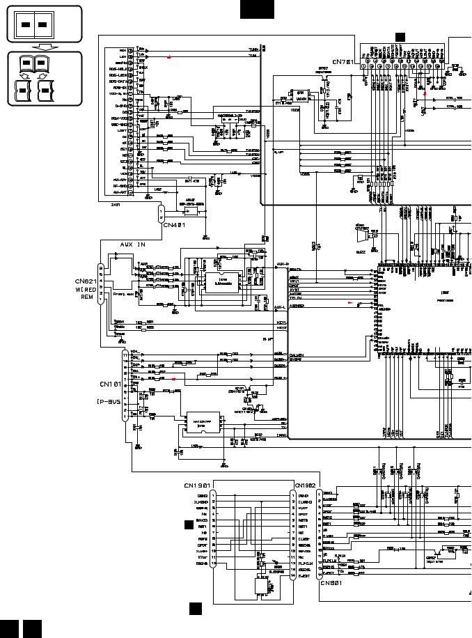
1 |
2 |
3 |
4 |
3.2 OVERALL CONNECTION DIAGRAM(GUIDE PAGE)
Note: When ordering service parts, be sure to refer to " EXPLODED VIEWS AND PARTS LIST" or "ELECTRICAL PARTS LIST".
A
|
|
Large size |
A-a |
A-b |
SCH diagram |
|
||
A-a |
A-b |
Guide page |
A-a |
A-b |
Detailed page |
B
C
D
A-a
C CN901
FM:-24dBs
AM:-24dBs
UNIT |
471/16 |
FM/AM TUNER |
|
CD:0.35dBs
|
|
|
15,000MHz |
|
RESET |
VCC |
XIN |
VSS |
XOUT |
CD- |
|
|
|
|
NC
NC
VCC |
VSS |
CE2 |
CE1 |
TUNPCK |
TUNPDI |
IP-Bus:2.21dBs
E
B
CN1801
EJECT
F
D PANEL UNIT
A D
14 |
|
DEH-P480MP/XU/UC |
|
|
1 |
2 |
|
3 |
4 |
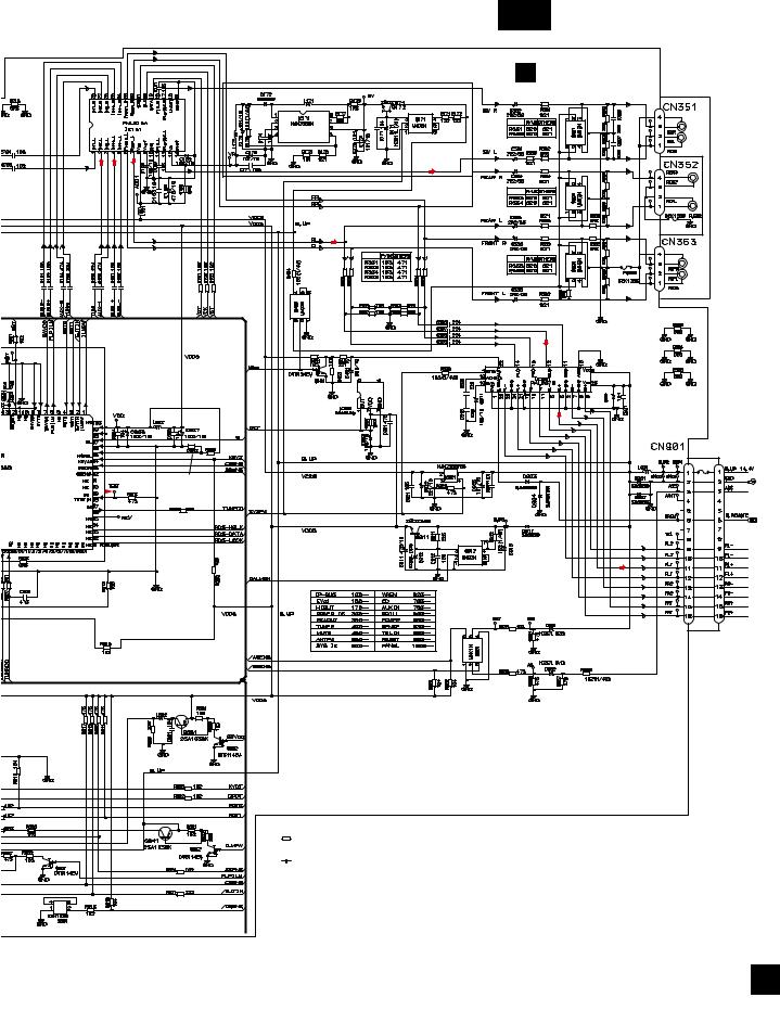
5 |
6 |
7 |
8 |
A-b
P480MP |
A TUNER AMP UNIT |
> 
FM,AM:-2.9dBs
CD:10.45dBs
IP-Bus:10.31dBs |
3A |
3A > |
|
|
332/16 |
|
XOUT |
|
|
|
AVCC |
|
|
|
VREF |
|
|
|
AVSS |
473:P4800MP |
|
CEK1208 10A |
|
|
600µH |
> |
|
|
|
|
|
473:P480MP |
|
|
|
104:P4800MP |
|
|
TUNPDO |
|
|
|
TUNPDI |
|
471/16 |
|
FM,AM:23.1dBs
CD:36.45dBs
IP-Bus:36.31dBs
NOTE : |
|
|
Symbol indicates a resistor. |
For resistors and capacitors in the circuit diagrams, their resistance |
|
No differentiation is made between chip resistors and |
values or capacitance values are expressed in codes: |
|
discrete resistors. |
|
|
Symbol indicates a capacitor. |
Ex. *Resistors |
|
No differentiation is made between chip capacitors and |
Code |
Practical value |
discrete capacitors. |
123 |
12k ohms |
|
103 |
10k ohms |
The > mark found on some component parts indicates |
|
|
the importance of the safety factor of the part. |
*Capacitors |
|
Therefore, when replacing, be sure to use parts of |
Code |
Practical value |
identical designation. |
103 |
0.01uF |
DSENS |
101/10 |
100uF/10V |
A
|
|
|
|
|
|
|
|
|
|
DEH- |
P480MP/XU/UC |
|
|
15 |
|
5 |
6 |
|
|
|
7 |
8 |
|
|
|
||||||
A
B
C
D
E
F
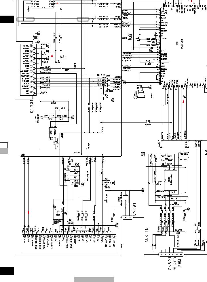
1
A
A-b 1
B |
CN901 |
|
|
|
|
|
C |
|
|
C
A-a A-b
D
-FM:24dBs |
AM:-24dBs |
E |
|
F
A-a
16
1
2 |
3 |
4 |
|
|
|
|
|
AVCC VREF |
AVSS |
TUNPDO |
2
|
XOUT |
15,000MHz |
VSS |
CD:0.35dBs |
XIN |
VCC |
|
|
CD-RESET |
NC |
NC |
471/16
FM/AMTUNERUNIT
DEH-P480MP/XU/UC
2 |
|
3 |
4 |

5 |
6 |
7 |
TUNPDO
3 |
4 |
TUNPDI
TUNPCK
CE1
CE2
VSS
VCC
NC
IP-Bus:2.21dBs |
B |
CN1801 |
DEH-P480MP/XU/UC
5 |
6 |
|
|
|
7 |
8
DSENS |
|
A |
|
|
|
A-b |
B
C
A-a A-b
EJECT |
|
D |
UNIT |
||
|
PANEL |
|
|
|
|
|
D |
|
|
|
E |
F
A-a D
17
8

1 |
2 |
3 |
4 |
10A
A
CEK1208 |
> |
> |
|
3A |
|
600µH
|
UNIT |
> |
|
3A |
332/16 |
|
|
B |
AMPTUNER |
|
|
|
|
|
|
|
|
|
|
|
|
|
|
|
A |
|
|
|
|
|
|
C |
P480MP |
|
|
|
|
|
|
|
|
|
|
|
|
|
|
|
A-b |
|
|
|
|
|
|
|
A-a |
|
|
|
|
|
|
D |
|
|
|
|
|
|
|
E |
|
2.9dBs-FM,AM: |
CD:10.45dBs |
Bus:10.31dBs-IP |
473:P4800MP |
473:P480MP |
104:P4800MP |
|
|
|
|
|
|
|
F
A-b |
1 |
2 |
|
AVCC VREF |
AVSS |
TUNPDO |
18 |
|
DEH-P480MP/XU/UC |
|
|
1 |
2 |
|
3 |
4 |

TUNPDO
5
3
6
7
4 P480MP/XU/UC-DEH
8 |
DSENS |
473:P480MP
104:P4800MP
 471/16
FM,AM:23.1dBs
CD:36.45dBs
IP-Bus:36.31dBs
NOTE :
Symbol indicates a resistor.
No differentiation is made between chip resistors and discrete resistors.
Symbol indicates a capacitor.
No differentiation is made between chip capacitors and discrete capacitors.
The > mark found on some component parts indicates the importance of the safety factor of the part. Therefore, when replacing, be sure to use parts of identical designation.
For resistors and capacitors in the circuit diagrams, their resistance values or capacitance values are expressed in codes:
Ex. *Resistors |
|
Code |
Practical value |
123 |
12k ohms |
103 |
10k ohms |
*Capacitors |
|
Code |
Practical value |
103 |
0.01uF |
101/10 |
100uF/10V |
19 |
-A |
|
|
|
|
|
|
|
|
|
|
|
|
|
|
|
|||
b |
|
|
|
A-a |
A-b |
|
|
|
|
|
|
|
|
|
|
|
|
||
|
|
F |
E |
D |
|
|
C |
B |
A |
|
|
|
|
5
6
7
8
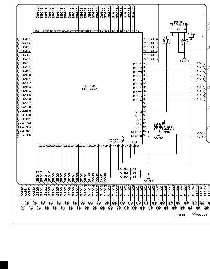
1 |
2 |
3 |
4 |
3.3 KEYBOARD UNIT
A
B
LCD DRIVER / KEY CONTROLLER
C
D
E
F
B
20 |
|
DEH-P480MP/XU/UC |
|
|
1 |
2 |
|
3 |
4 |
5 |
6 |
7 |
B KEYBOARD UNIT
FUNCTION
DISPLAY
DEH-P480MP/XU/UC
5 |
6 |
|
|
|
7 |
8
A
D
B
CN1901
C
D
E
F
B
21
8
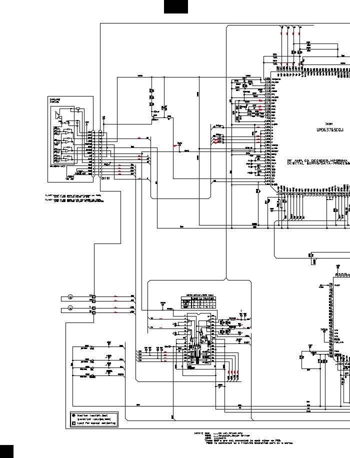
1 |
2 |
3 |
4 |
3.4 CD MECHANISM MODULE(GUIDE PAGE)
A
C-a
S |
C |
T |
F |
S |
C |
T |
F |
B |
PICKUP UNIT(P10.5)(SERVICE) |
|
$
C
D
F
T
F
T
F
F
T
T
SWITCHES: |
|
CD CORE UNIT(S10.5COMP1) |
|
S901:HOME SWITCH.......... |
ON-OFF |
S903:DSCSNS SWITCH...... |
ON-OFF |
S904:12EJ SWITCH............. |
ON-OFF |
S905:8EJ SWITCH............... |
ON-OFF |
The underlined indicates the switch position.
F
F
T
T
@
!
M1 |
CXC6742 |
|
CD DRIVER |
|
SPINDLE MOTOR |
|
|
|
|
|
|
S |
|
|
|
|
S |
|
|
|
|
C |
|
# |
|
|
|
|
|
|
|
C |
|
|
M2 |
CXC4026 |
T |
|
S |
LOADING/CARRIAGE MOTOR |
|
|||
8 |
|
6 |
||
|
|
|
||
|
|
F |
|
C |
|
|
9 |
|
7 |
|
|
|
|
|
|
|
|
4 |
|
E |
|
|
|
|
|
|
F |
|
|
|
|
F |
|
|
|
3 |
T |
|
|
|
|
T |
|
|
|
2 |
|
|
|
|
1 |
|
S S C |
C |
|
|
|
|
|
F
C
22 |
|
DEH-P480MP/XU/UC |
|
|
1 |
2 |
|
3 |
4 |
NC |
NC |
NC |
NC |
NC |
NC
NC
NC
NC
NC
NC
NC
NC
NC
NC
NC
NC
NC
NC
NC
NC
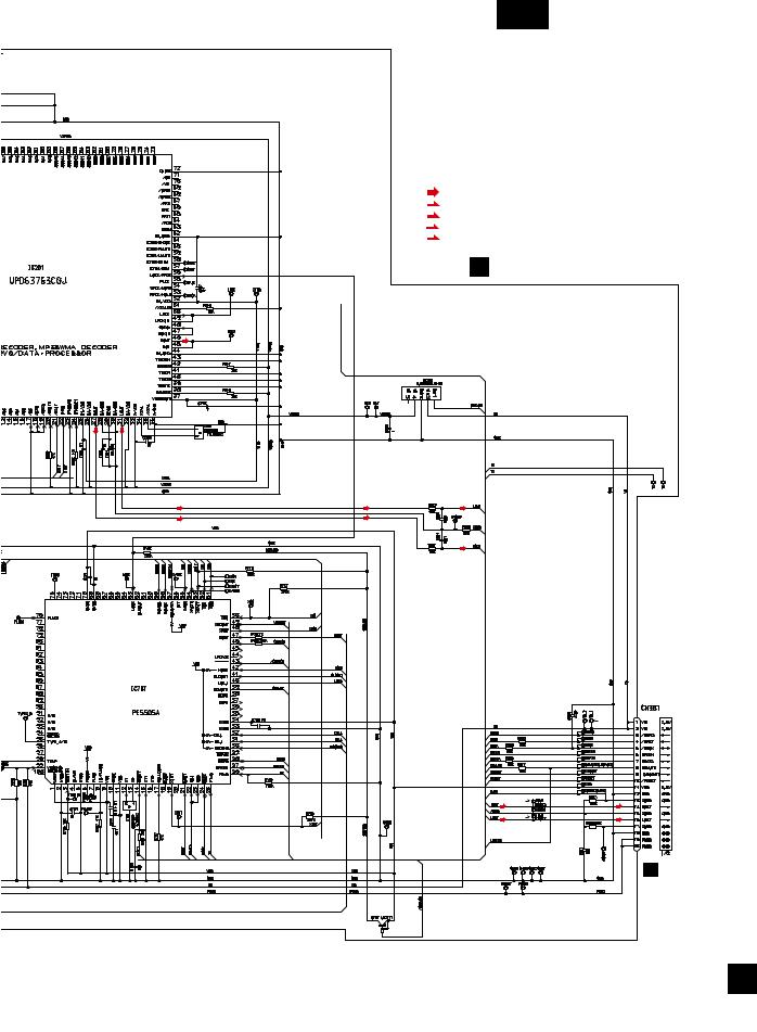
5 |
6 |
7 |
C-b
SIGNAL LINE
F |
FOCUS SERVO LINE |
|
T |
||
TRACKING SERVO LINE |
||
C |
||
CARRIAGE SERVO LINE |
||
S |
||
SPINDLE SERVO LINE |
||
|
8
A
Decimal points for resistor |
B |
|||
and capacitor fixed values |
|
|||
are expressed as : |
|
|||
2.2 |
← |
2R2 |
|
|
0.022 |
← |
R022 |
|
|
|
|
|||
C CD CORE UNIT(S10.5COMP1)

 0
0
|
|
|
+ 3.3 V REGULATOR |
|
|
|
C |
|
|
|
D |
NC NC NC NC NC |
NC NC NC NC NC |
NC NC |
|
NC |
|
|
|
NC |
|
|
|
NC |
|
|
|
NC |
|
|
CD3VON(MCKRQ) |
NC |
|
|
SRAMLEVEL2 |
NC |
|
|
|
NC |
|
|
ADENA |
NC |
|
|
|
NC |
|
|
|
NC |
|
|
|
NC |
|
|
|
NC |
|
|
|
NC |
|
|
|
NC |
|
|
SRAMLEVEL1 |
|
|
|
SRAMLEVEL0 |
|
|
|
5 |
|
CD CONTROLLER |
(S904) |
|
|
(S905) |
||
NC |
|
|
E |
NC |
|
|
|
|
|
NC |
|
|
|
|
^ |
|
|
|
% |
|
|
|
A CN701 |
F
C
|
|
|
|
|
|
|
|
|
|
DEH- |
P480MP/XU/UC |
|
|
23 |
|
5 |
6 |
|
|
|
7 |
8 |
|
|
|
||||||
Loading...