

Page 1

Installation Manual
Manuel d’installation
NAVIGATION AV SYSTEM
SYSTEME DE NAVIGATION AV
SISTEMA DI NAVIGAZIONE AV
SISTEMA DE NAVEGACIÓN AV
NAVIGATIONS-/AV-SYSTEM
AV NAVIGATIESYSTEEM
AVIC-F550BT
Some wiring and installation are described in the
separate installation manual.
Certains câblages et procédés d’installation sont décrits
dans le manuel d’installation séparé.
Alcuni dati di cablaggio e installazione sono descritti nel
Manuale d’installazione separato.
En el manual de instalación independiente se describe
parte del proceso de cableado e instalación.
Gewisse Verkabelungs- und Installationsarbeiten sind in
der separaten Einbauanleitung beschrieben.
Sommige bedradings- en installatie-informatie staat in
de afzonderlijke installatiehandleiding.
English NederlandsDeutschEspañolItalianoFrançais
Page 2
Contents
Precautions
Your new navigation system and this
manual 3
Important safeguards 3
Handling the microSD card 4
Connecting the system
Precautions before connecting the
system 5
Before installing this product 5
To prevent damage 6
– Notice for the blue/white lead 6
Parts supplied 7
Connecting the system 8
Connecting the control line cable 10
When connecting to separately sold power
amp 11
When connecting a rear view camera 12
When connecting the external video
component 13
– Using an AV input (AUX) 13
– Using an AV input (USB) 13
When connecting the rear display 14
– When using a rear display connected to
rear video output 14
Installation
Precautions before installation 15
To avoid electromagnetic interference 15
Before installing 15
Installing the navigation system 16
– Installation notes 16
– Parts supplied 16
– Before installing this navigation
unit 17
– Installation using the screw holes on
the side of the navigation unit 17
Installing the GPS aerial 18
– Installation notes 18
– Parts supplied 18
2
Engb
– When installing the aerial inside the
vehicle (on the dashboard or rear
shelf) 19
Installing the microphone 20
– Parts supplied 20
– Mounting on the sun visor 20
– Installation on the steering column 21
After installation
After installing this product 22
Page 3
Precautions
Your new navigation
system and this manual
! The navigation features of this product
(and the rear view camera option if purchased) are intended solely to aid you in
the operation of your vehicle. It is not a substitute for your attentiveness, judgement
and care when driving.
! Never use this navigation system to route
to hospitals, police stations, or similar facilities in an emergency. Please call the appropriate emergency number.
! Do not operate this navigation system (or
the rear view camera option if purchased) if
doing so will divert your attention in any
way from the safe operation of your vehicle.
Always observe safe driving rules and follow all existing traffic regulations. If you experience difficulty in operating the system
or reading the display, park your vehicle in
a safe location and apply the handbrake before making the necessary adjustments.
! This manual explains how to install this na-
vigation system in your vehicle. Operation
of this navigation system is explained in
the separate manuals for the navigation
system.
! Do not install this product where it may (i)
obstruct the driver’s vision, (ii) impair the
performance of any of the vehicle’s operating systems of safety features, including
airbags, hazard lamp buttons, or (iii) impair
the driver’s ability to safely operate the vehicle. In some cases, it may not be possible
to install this product because of the vehicle type or the shape of the vehicle interior.
Section
01
English
Important safeguards
WARNING
Pioneer does not recommend that you install
your navigation system yourself. This product is designed for professional installation
only. We recommend that only authorised
Pioneer service personnel, who have special
training and experience in mobile electronics, set up and install this product. NEVER
SERVICE THIS PRODUCT YOURSELF. Installing or servicing this product and its connecting cables may expose you to the risk of
electric shock or other hazards, and can
cause damage to the navigation system that
is not covered by warranty.
! Read this manual fully and carefully before
installing your navigation system.
! Keep this manual handy for future refer-
ence.
! Pay close attention to all warnings in this
manual and follow the instructions carefully.
! This navigation system may in certain cir-
cumstances display inaccurate position of
your vehicle, the distance of objects shown
on the screen, and compass directions. In
addition, the system has certain limitations, including the inability to identify oneway streets, temporary traffic restrictions
and potentially unsafe driving areas. Please
exercise your own judgement in the light of
actual driving conditions.
! As with any accessory in your vehicle’s in-
terior, the navigation system should not divert your attention from the safe operation
of your vehicle as it may result in serious
injury or death. If you experience difficulty
in operating the system or reading the display, please make adjustments while safely
parked.
! Please remember to wear your seat belt at
all times while operating your vehicle. If
you are in an accident, your injuries can be
considerably more severe if your seat belt
is not properly fastened.
Engb
3
Page 4
Section
01
Precautions
! Certain country and government laws may
prohibit or restrict the placement and use
of this system in your vehicle. Please comply with all applicable laws and regulations
regarding the use, installation and operation of your navigation system.
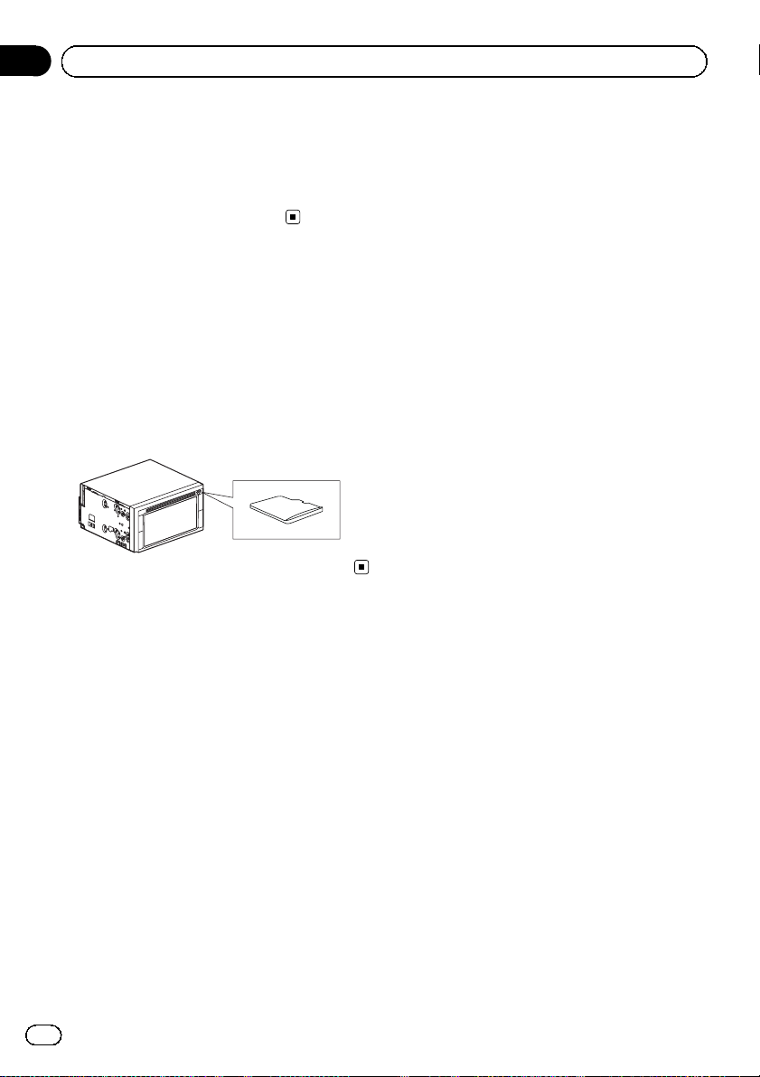
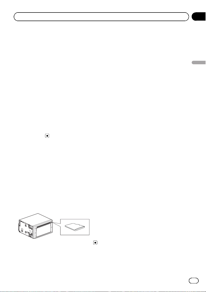
Handling the microSD card
A microSD card is installed in the SD card slot
of this navigation system. Without the
microSD card, the navigation system will not
operate properly.
Do not remove the microSD card from the SD
card slot except when performing software updates.
= For details, refer to Operation Manual.
4
Engb
Page 5
Connecting the system
Section
02
Precautions before
connecting the system
WARNING
Do not take any steps to tamper with or disable the handbrake interlock system which
is in place for your protection. Tampering
with or disabling the handbrake interlock
system could result in serious injury or
death.
CAUTION
! If you decide to perform the installation
yourself, and have special training and experience in the mobile electronics installations, please carefully follow all of the
steps in the installation manual.
! Secure all wiring with cable clamps or
electrical tape. Do not allow any bare wiring to remain exposed.
! Do not directly connect the yellow lead of
this product to the vehicle battery. If the
lead is directly connected to the battery,
engine vibration may eventually cause
the insulation to fail at the point where
the wire passes from the passenger compartment into the engine compartment. If
the yellow lead’s insulation tears as a result of contact with metal parts, short-circuiting can occur, resulting in
considerable danger.
! It is extremely dangerous to allow cables
to become wound around the steering column or gearstick. Be sure to install this
product, its cables, and wiring away in
such so that they will not obstruct or hinder driving.
! Make sure that the cables and wires will
not interfere with or become caught in
any of the vehicle’s moving parts, especially the steering wheel, gearstick, handbrake, sliding seat tracks, doors, or any of
the vehicle’s controls.
! Do not route wires where they will be ex-
posed to high temperatures. If the insulation heats up, wires may become
damaged, resulting in a short circuit or
English
malfunction and permanent damage to
the product.
! Do not cut the GPS aerial cable to shorten
it or use an extension to make it longer.
Altering the aerial cable could result in a
short circuit or malfunction.
! Do not shorten any leads. If you do, the
protection circuit (fuse holder, fuse resistor or filter, etc.) may fail to work properly.
! Never feed power to other electronic pro-
ducts by cutting the insulation of the
power supply lead of the navigation system and tapping into the lead. The current
capacity of the lead will be exceeded,
causing overheating.
Before installing this product
! Use this unit with a 12-volt battery and ne-
gative earthing only. Failure to do so may
result in a fire or malfunction.
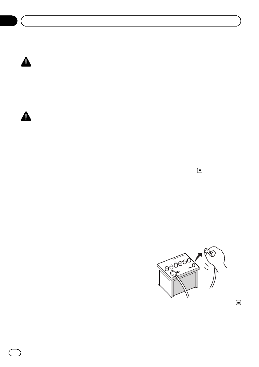
! To avoid shorts in the electrical system, be
sure to disconnect the (–) battery cable before installation.
Engb
5
Page 6
Section
02
Connecting the system
To prevent damage
WARNING
! Use speakers over 50 W (output value)
and between 4 W to 8 W (impedance value).
Do not use 1 W to 3 W speakers for this
unit.
! The black lead is earth. Please earth this
lead separately from the earth of high-current products such as power amps. Do not
earth more than one product together
with the earth from another product. For
example, you must separately earth any
amp unit away from the earth of this navigation system. Connecting earths together can cause a fire and/or damage the
products if their earths became detached.
! When replacing the fuse, be sure to only
use a fuse of the rating prescribed on this
product.
! When disconnecting a connector, pull the
connector itself. Do not pull the lead, as
you may pull it out of the connector.
! This product cannot be installed in a vehi-
cle without ACC (accessory) position on
the ignition switch.
C
C
A
O
F
N
F
O
S
T
A
R
T
O
F
N
F
O
S
T
A
R
T
! Since a unique BPTL circuit is employed,
do not directly earth the * side of the
speaker lead or connect the * side of another side of the speaker lead together. Be
sure to connect the * side of the speaker
lead to the * side of the speaker lead on
this navigation system.
! If the RCA pin jack on this product will not
be used, do not remove the caps attached
to the end of the connector.
Notice for the blue/white lead
! When the ignition switch is turned on (ACC
ON), a control signal is output through the
blue/white lead. Connect to an external
power amp’s system remote control terminal, the auto-aerial relay control terminal,
or the aerial booster power control terminal
(max. 300 mA 12V DC). The control signal
is output through the blue/white lead, even
if the audio source is switched off.
! Be sure not to use this lead as the power
supply lead for the external power amps.
Such connection could cause excessive
current drain and malfunction.
! Be sure not to use this lead as the power
supply lead for the auto-aerial or aerial
booster. Such connection could cause excessive current drain and malfunction.
ACC position No ACC position
! To avoid short-circuiting, cover the discon-
nected lead with insulating tape. It is especially important to insulate all unused
speaker leads, which if left uncovered may
cause a short circuit.
! Attach the connectors of the same colour
to the corresponding coloured port, i.e.,
blue connector to the blue port, black to
black, etc.
! Refer to the owner’s manual for details on
connecting the power amp and other units,
then make connections accordingly.
6
Engb
Page 7
Connecting the system
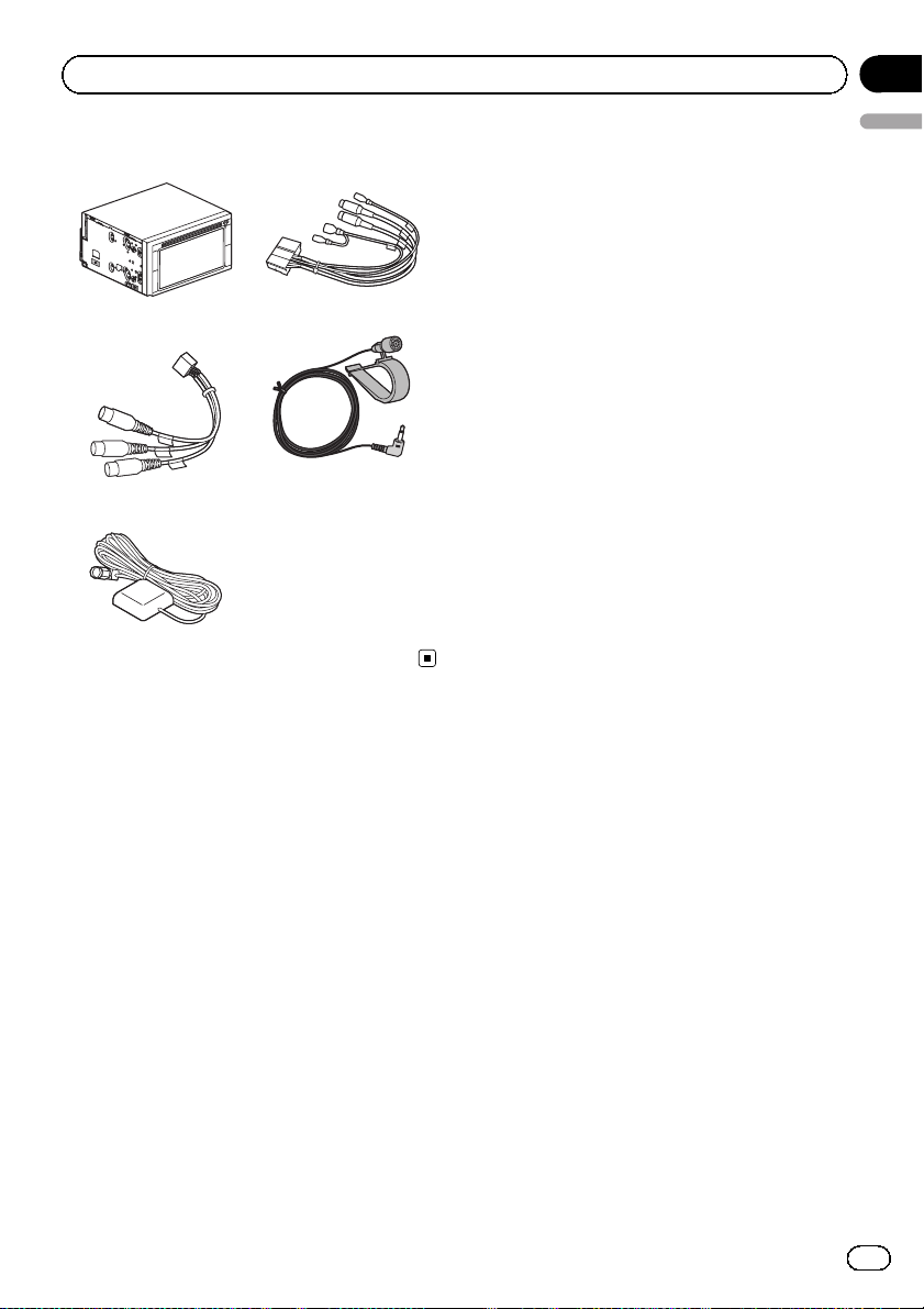
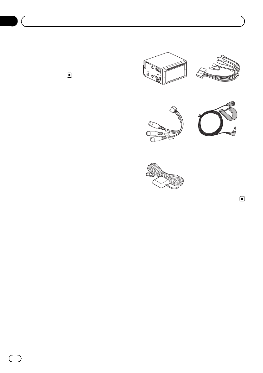
Parts supplied
The navigation unit Control line cable
AV connector cord Microphone
GPS aerial
Section
02
English
Engb
7
Page 8
Section
02
Connecting the system
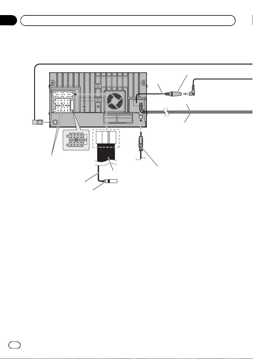
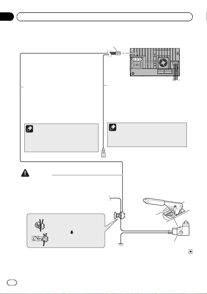
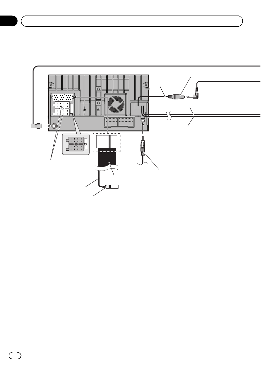
Connecting the system
The navigation unit
12 cm
(*1)
Power cord
For connection, refer to the
wiring and installation manual
separately supplied.
Wired remote input (SWC)
Please refer to the instruction manual for the Hard-wired remote
control adapter.
(*1)
Make sure that the three yellow, green and blue connectors are attached before
connecting the system.
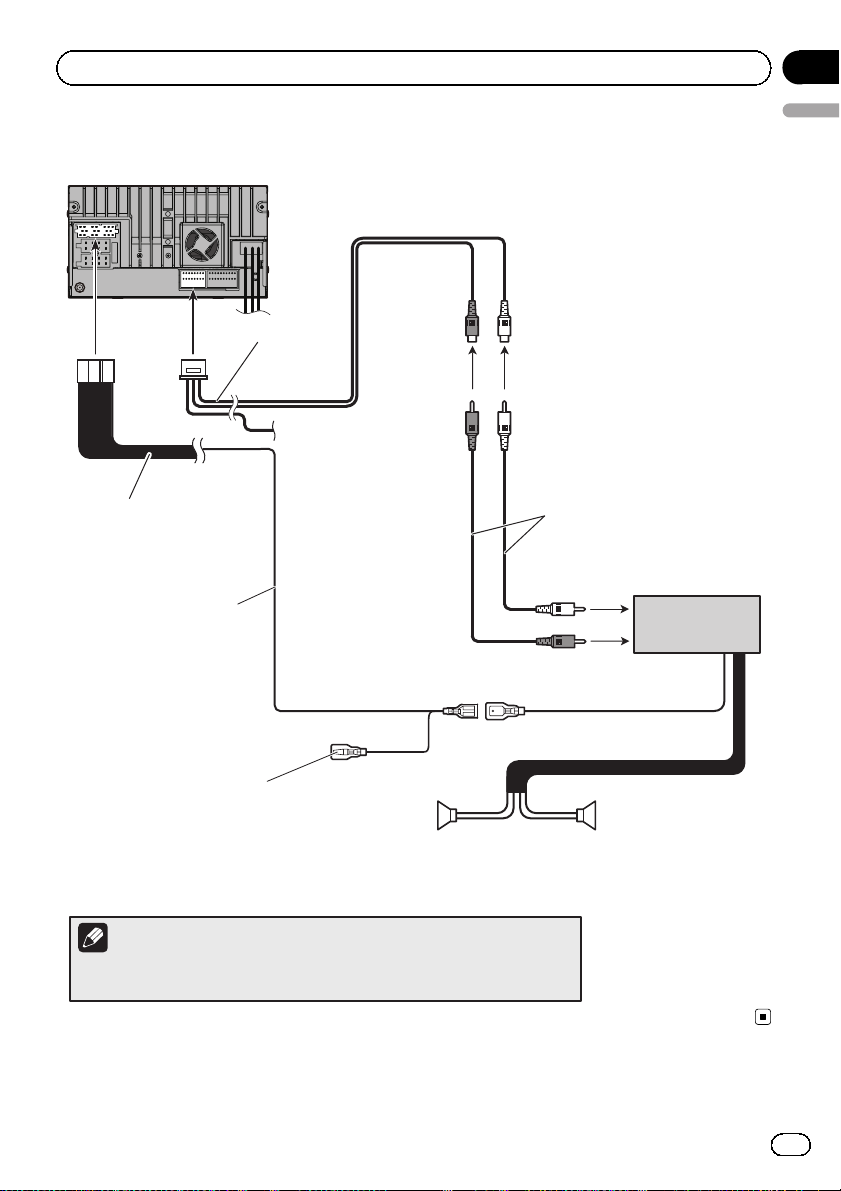
(*2)
Connect either the USB interface cable for iPod or an appropriate USB storage
device.
(*3)
When connecting your iPod, both connections are necessary.
(*4)
For details concerning operations and compatibility, refer to Operation
Manual.
Fuse (15 A)
25 cm
Control line cable
Vehicle aerial
Microphone jack(MIC)
12 cm
12 cm
8
Engb
Page 9
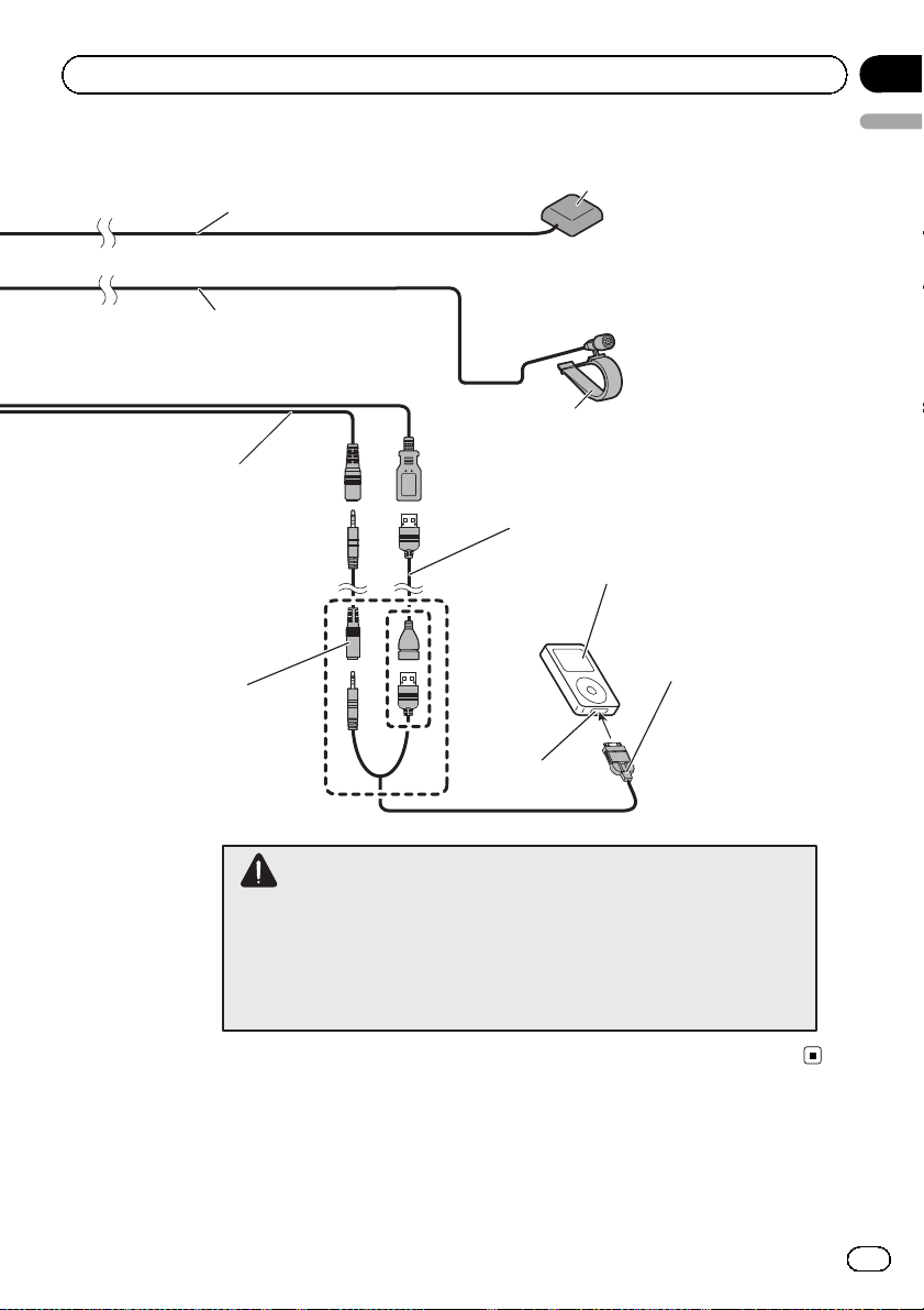
Connecting the system
3 m
4 m
AV cable
(iPod/AV IN)
Section
02
English
GPS aerial
Microphone
USB cable
(sold separately)
(*4)
USB interface cable for iPod
(sold separately)
AV cable
(sold separately)
(*3)
(*2)
iPod or iPhone
Dock Connector
port
WARNING
· To avoid the risk of accident and the potential violation of applicable laws, this
product should never be used while the vehicle is being driven except for
navigation purposes. And, also rear displays should not be in a location where it
is a visible distraction to the driver.
· In some countries, the viewing of images on a display inside a vehicle even by
persons other than the driver may be illegal. Where such regulations apply they
must be obeyed and this product’s video source should not be used.
Engb
9
Page 10
Section
02
Connecting the system
Connecting the control line cable
Control line cable
The navigation unit
Green/white (BRAKE)
Used to detect the ON/OFF status of the
handbrake. This lead must be connected to the
power supply side of the handbrake switch.
If this connection is made incorrectly or
omitted, certain functions of this product
will be unusable.
Note
The position of the handbrake switch vary
depending on the vehicle model. For details,
consult your authorised Pioneer dealer or an
installation professional.
WARNING
GREEN/WHITE LEAD AT POWER CONNECTOR IS
DESIGNED TO DETECT PARKED STATUS AND MUST
BE CONNECTED TO THE POWER SUPPLY SIDE OF THE
HANDBRAKE SWITCH. IMPROPER CONNECTION OR
USE OF THIS LEAD MAY VIOLATE APPLICABLE LAW
AND MAY RESULT IN SERIOUS INJURY OR DAMAGE.
Connection method
Clamp the lead of the power supply
side of the handbrake switch.
Pink (REVERSE)
This is connected so that the this product can detect
whether the vehicle is moving forwards or
backwards. Connect the pink lead to the lead whose
voltage changes when the reverse gear is engaged.
Unless connected, the sensor may not detect your
vehicle travelling forward/backward properly, and
thus the position of your vehicle detected by the
sensor may be misaligned from the actual position.
Note
When you use a rear view camera, please make
sure to connect this lead. Otherwise you cannot
switch to the rear view camera picture.
Power supply side
10
Engb
Clamp firmly with needle-nosed
pliers.
Earth side
Handbrake switch
Page 11
Connecting the system
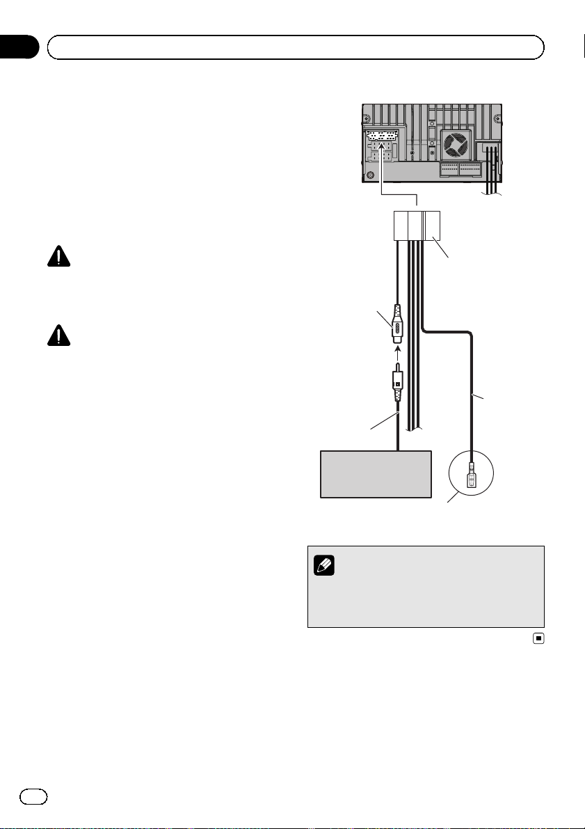
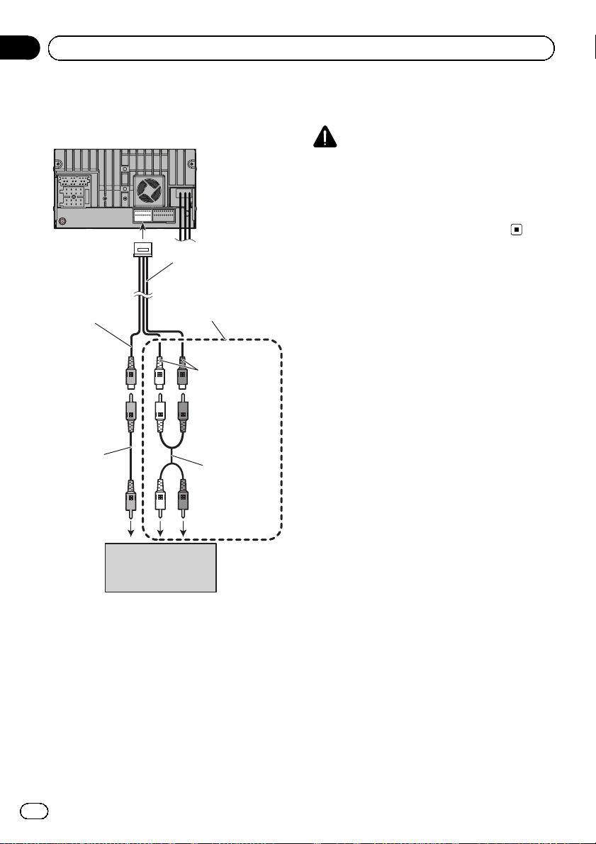
When connecting to separately sold power amp
The navigation unit
Section
02
English
AV connector cord
Control line cable
Blue/white (P.CONT)
To system control terminal of
the power amp
(max. 300 mA 12 V DC).
Connect to the power supply line
terminal (sold separately) equivalent to
P.CONT.
Red
(FULL/SW)
Right
Rear speaker or
Subwoofer
White
(FULL/SW)
Left
RCA cables
(sold separately)
Power amp
(sold separately)
System remote control
Rear speaker or
Subwoofer
Note
You can change the RCA output of the subwoofer depending on your subwoofer
system. (Refer to Operation Manual.)
Engb
11
Page 12
Y
Section
02
Connecting the system
When connecting a rear
view camera
When this product is used with a rear view
camera, it is possible to automatically switch
from the video to rear view image when the
gearstick is moved to REVERSE (R). Rear-
View mode also allows you to check what is
behind you while driving.
p For details, refer to Operation Manual.
WARNING
USE INPUT ONLY FOR REVERSE OR MIRROR
IMAGE REAR VIEW CAMERA. OTHER USE MAY
RESULT IN INJURY OR DAMAGE.
CAUTION
! The screen image may appear reversed.
! The rear view camera is used as an aid to
keep an eye on trailers, or backing into a tight
parking spot. Do not use this function for entertainment purposes.
! Objects in rear view may appear closer or
more distant than in reality.
! Please note that the image area shown by the
rear view camera may differ slightly when fullscreen images are displayed when backing
and when checking the rear of the vehicle
while moving forward.
The navigation unit
Control line cable
ellow
(CAMERA VIDEO)
Pink
(REVERSE)
RCA cable
Rear view camera
(e.g. ND-BC6)
(sold separately)
For more details about the wiring, refer to Connecting
the control line cable on page 10.
Note
Connect the navigation system to the rear view
camera only. Do not connect to any other
12
Engb
equipment.
Page 13
T
Connecting the system
When connecting the
external video component
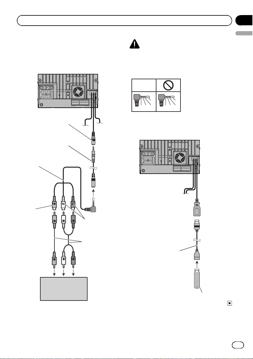
Using an AV input (AUX)
The navigation unit
AV cable
(iPod/AV IN)
AV cable
(sold separately)
Mini-jack AV cable
(CD-RM10)
(sold separately)
CAUTION
Be sure to use a mini-jack AV cable (CD-RM10)
(sold separately) for wiring. If you use other
cables, the wiring position might differ resulting
in disturbed images and sounds.
OK
L : Left audio (White)
L
GVR
Using an AV input (USB)
The navigation unit
R : Right audio (Red)
L
V : Video (Yellow)
GRV
G : Earth
Section
02
English
Yellow
White, Red
RCA cables
(sold separately)
USB cable
(sold separately)
o video output
External video
component
(sold separately)
To audio outputs
USB storage device
Engb
13
Page 14
Section
02
Connecting the system
When connecting the rear
display
The navigation unit
AV connector cord
When connecting a rear
display with an audio RCA
Yellow
RCA cable
(sold separately)
To video input
input
White, Red
RCA cable
(sold separately)
To audio inputs
When using a rear display
connected to rear video output
WARNING
NEVER install the rear display in a location
that enables the driver to watch the video
source while driving.
This navigation system’s rear video output is for
connection of a display to enable passengers in
the rear seats to watch the video source.
14
Rear display with
RCA input jacks
Engb
Page 15

Installation
Section
03
Precautions before
installation
CAUTION
! Never install this product in places where,
or in a manner that:
— Could injure the driver or passengers if
the vehicle stops suddenly.
— May interfere with the driver’s opera-
tion of the vehicle, such as on the floor
in front of the driver’s seat, or close to
the steering wheel or gearstick.
! Make sure there is nothing behind the
dashboard or panelling when drilling
holes in them. Be careful not to damage
fuel lines, brake lines, electronic components, communication wires or power
cables.
! When using screws, do not allow them to
come into contact with any electrical lead.
Vibration may damage wires or insulation,
leading to a short circuit or other damage
to the vehicle.
! To ensure proper installation, be sure to
use the supplied parts in the manner specified. If any parts are not supplied with
this product, use compatible parts in the
manner specified after you have the parts’
compatibility checked by your dealer. If
parts other than supplied or compatible
ones are used, they may damage internal
parts of this product or they may work
loose and the product may become detached.
! It is extremely dangerous to allow cables
to become wound around the steering column or gearstick. Be sure to install this
product, its cables, and wiring away in
such so that they will not obstruct or hinder driving.
! Make sure that leads cannot get caught in
a door or the sliding mechanism of a seat,
resulting in a short circuit.
! Please confirm the proper function of
your vehicle’s other equipment after installation of the navigation system.
! Do not install this navigation system
English
where it may (i) obstruct the driver’s vision, (ii) impair the performance of any of
the vehicle’s operating systems or safety
features, including airbags, hazard lamp
buttons or (iii) impair the driver’s ability
to safely operate the vehicle.
! Install the navigation system between the
driver’s seat and front passenger seat so
that it will not be hit by the driver or passenger if the vehicle stops quickly.
! Never install the navigation system in
front of or next to the place in the dashboard, door, or pillar from which one of
your vehicle’s airbags would deploy.
Please refer to your vehicle’s owner’s
manual for reference to the deployment
area of the frontal airbags.
! Failure to follow all of these precautions
may result in serious injury or death.
To avoid electromagnetic
interference
In order to prevent interference, set the following items as far as possible from this navigation system, other cables or leads:
! FM, MW/LW aerial and its lead
! GPS aerial and its lead
In addition, you should lay or route each aerial
lead as far as possible from other aerial leads.
Do not bind, lay or route them together, or
cross them. Electromagnetic noise will increase the potential for errors in the vehicle’s
location display.
Before installing
! Consult with your nearest dealer if installa-
tion requires drilling holes or other modifications of the vehicl e.
! Before making a final installation of this
product, temporarily connect the wiring to
confirm that the connections are correct
and the system works properly.
Engb
15
Page 16
Section
03
Installation
Installing the navigation
system
Installation notes
! Do not install the navigation system in
places subject to high temperatures or humidity, such as:
— Places close to a heater, vent or air con-
ditioner.
— Places exposed to direct sunlight, such
as on top of the dashboard.
— Places that may be exposed to rain,
such as close to the door or on the vehicle’s floor.
! Install this navigation system in an area
strong enough to bear its weight. Choose a
position where this navigation system can
be firmly installed, and install it securely. If
this navigation system is not securely installed, the current location of the vehicle
cannot be displayed correctly.
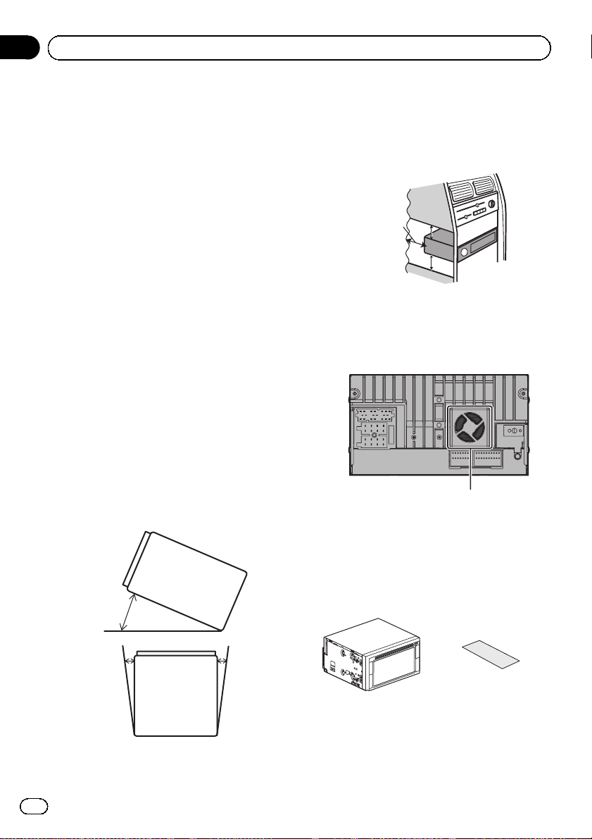
! Install the navigation unit horizontally on a
surface within 0 to 30 degrees tolerance
(within 5 degrees to the left or right). Improper installation of the unit with the surface
tilted more than these tolerances increases
the potential for errors in the vehicle’s location display, and might otherwise cause reduced display performance.
! When installing, to ensure proper heat dis-
persal when using this unit, make sure you
leave ample space behind the rear panel
and wrap any loose cables so they are not
blocking the vents.
Leave ample
space
5 cm
5 cm
! The cords must not cover the area shown
in the figure below. This is necessary to
allow the amps and navigation mechanism
to dissipate heat.
Do not cover this area.
! The semiconductor laser will be damaged
if it overheats, so don’t install the navigation unit anywhere hot — for instance, near
a heater outlet.
16
Engb
30°
5° 5°
Parts supplied
The navigation unit Tape
(2 pcs.)
Page 17
T
Installation
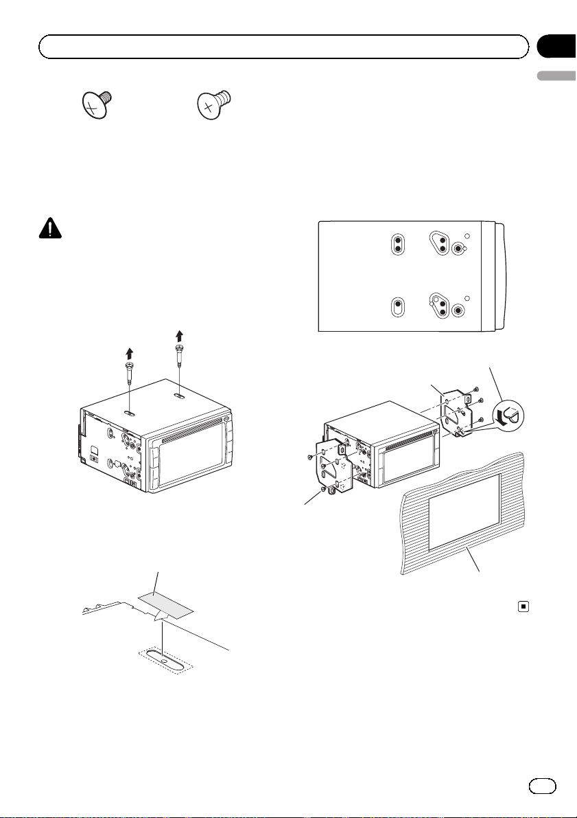
Truss head screw
(5 mm × 6 mm)
(6 pcs.)
Before installing this
navigation unit
CAUTION
The disc player will not operate properly if
you do not remove the two bolts from the navigation unit. Using the disc player without
removing the bolts may cause a malfunction.
1 Remove the two shipping bolts.
Flush surface screw
(5 mm × 7 mm)
(6 pcs.)
Section
03
English
Installation using the screw holes
on the side of the navigation unit
% Fastening the navigation unit to the
factory radio-mounting bracket.
Position the navigation unit so that its screw
holes are aligned with the screw holes of the
bracket, and tighten the screws at three locations on each side.
If the pawl interferes with installation,
you may bend it down out of the way.
Factory radio-mounting bracket
2 Seal the two screw holes with the
pieces of tape supplied with the navigation
unit.
Tape
russ he ad scr ew or
u sh sur face screw
Be sure to use the
scre ws sup pl ied wit h
this navigation
sy ste m.
Dashboard or console
Engb
17
Page 18
Section
03
Installation
Installing the GPS aerial
CAUTION
Do not cut the GPS aerial lead to shorten it
or use an extension to make it longer. Altering the aerial cable could result in a short circuit or malfunction and permanent damage
to the navigation system.
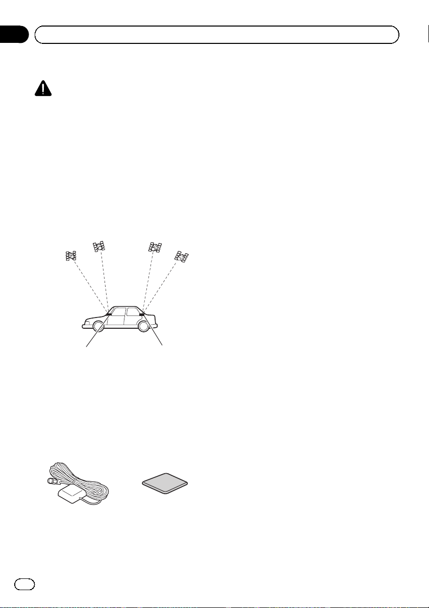
Installation notes
! The aerial should be installed on a level sur-
face where radio waves will be blocked as
little as possible. Radio waves cannot be received by the aerial if reception from the satellite is blocked.
Dashboard Rear shelf
! Take care not to pull the aerial lead when
removing the GPS aerial. The magnet attached to the aerial is very powerful, and
the lead may become detached.
! Do not paint the GPS aerial, as this may af-
fect its performance.
Parts supplied
GPS aerial Double-sided tape
18
Engb
Page 19
Installation
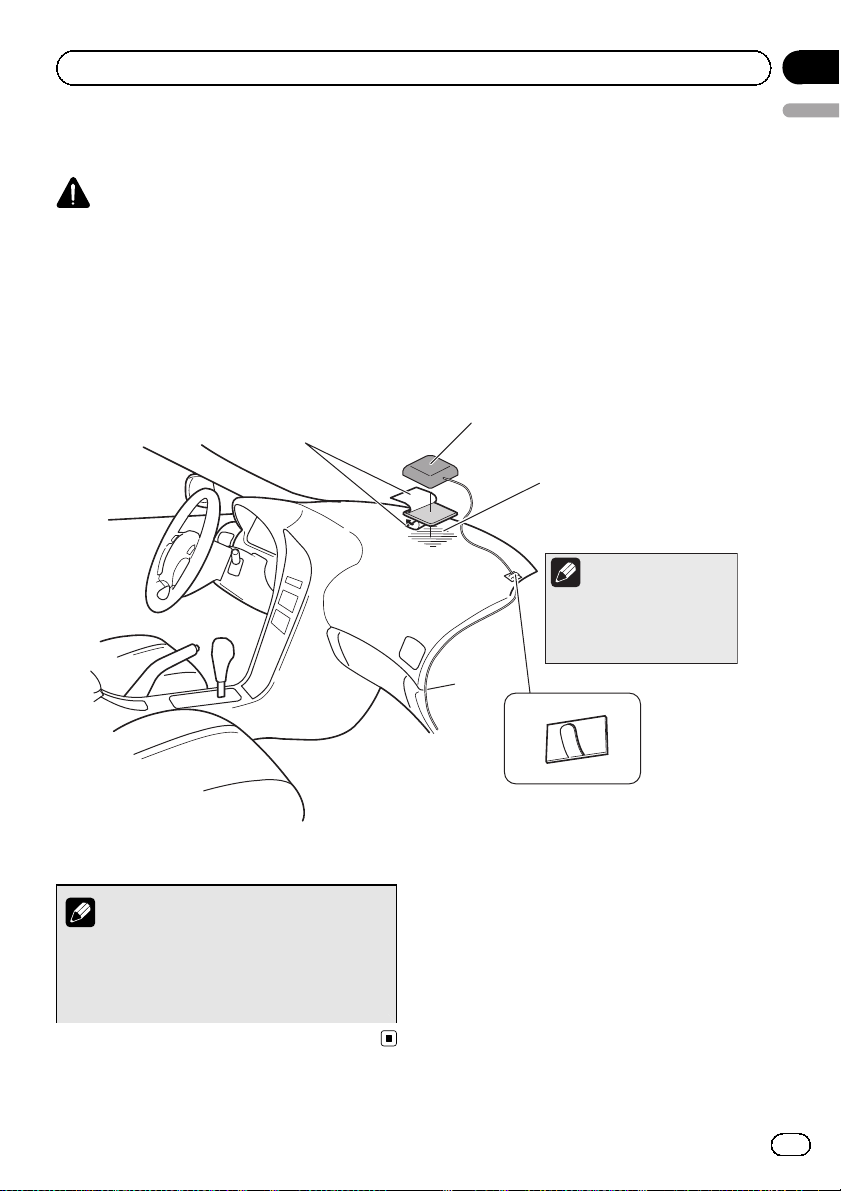
When installing the aerial inside the vehicle (on the dashboard or
rear shelf)
WARNING
Do not install the GPS aerial over any sensors or vents on the dashboard of the vehicle, as
doing so may interfere with the proper functioning of such sensors or vents and may compromise the ability of the double-sided tape under the GPS aerial to properly and securely affix to
the dashboard.
Affix the double-sided tape on the surface as
level as possible where the GPS aerial faces
the window. Place the GPS aerial on the double-sided tape.
Double-sided tape
Peel off the protective sheet.
GPS aerial
Make sure the surface is free of
moisture, dust, grime, oil, etc.,
before affixing the double-sided
tape.
Note
The double-sided tape
contains a strong adhesive
which may leave a mark on
the surface if it is removed.
Section
03
English
Note
Some models use window glass that does not
allow signals from GPS satellites to pass
through. On such models, install the GPS aerial on the outside of the vehicle.
Clamps
Use separately sold clamps
to secure the lead where necessary
inside the vehicle.
Engb
19
Page 20
Section
03
Installation
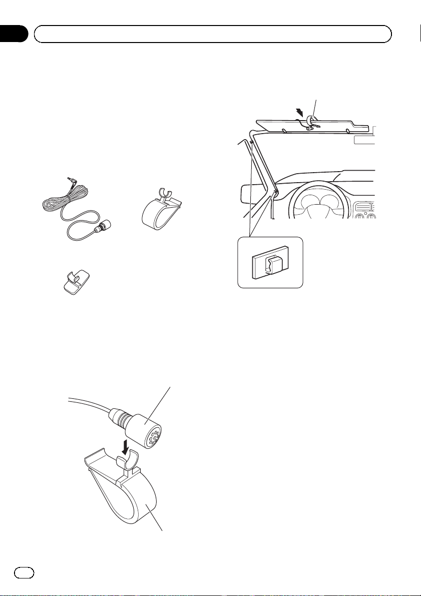
Installing the microphone
! Install the microphone in a place where its
direction and distance from the driver
make it easiest to pick up the driver’s voice.
! Make sure to connect the microphone to
the navigation system after the system is
turned off (ACC OFF).
Parts supplied
Microphone Microphone clip
Microphone holder
Mounting on the sun visor
1 Install the microphone to the microphone clip.
Microphone
2 Attach the microphone clip to the sun
visor.
Microphone clip
Clamps
Use separately sold clamps to secure the lead
where necessary inside the vehicle.
Install the microphone on the sun visor when
it is in the up position. It cannot recognise the
driver’s voice if the sun visor is in the down position.
20
Microphone clip
Engb
Page 21
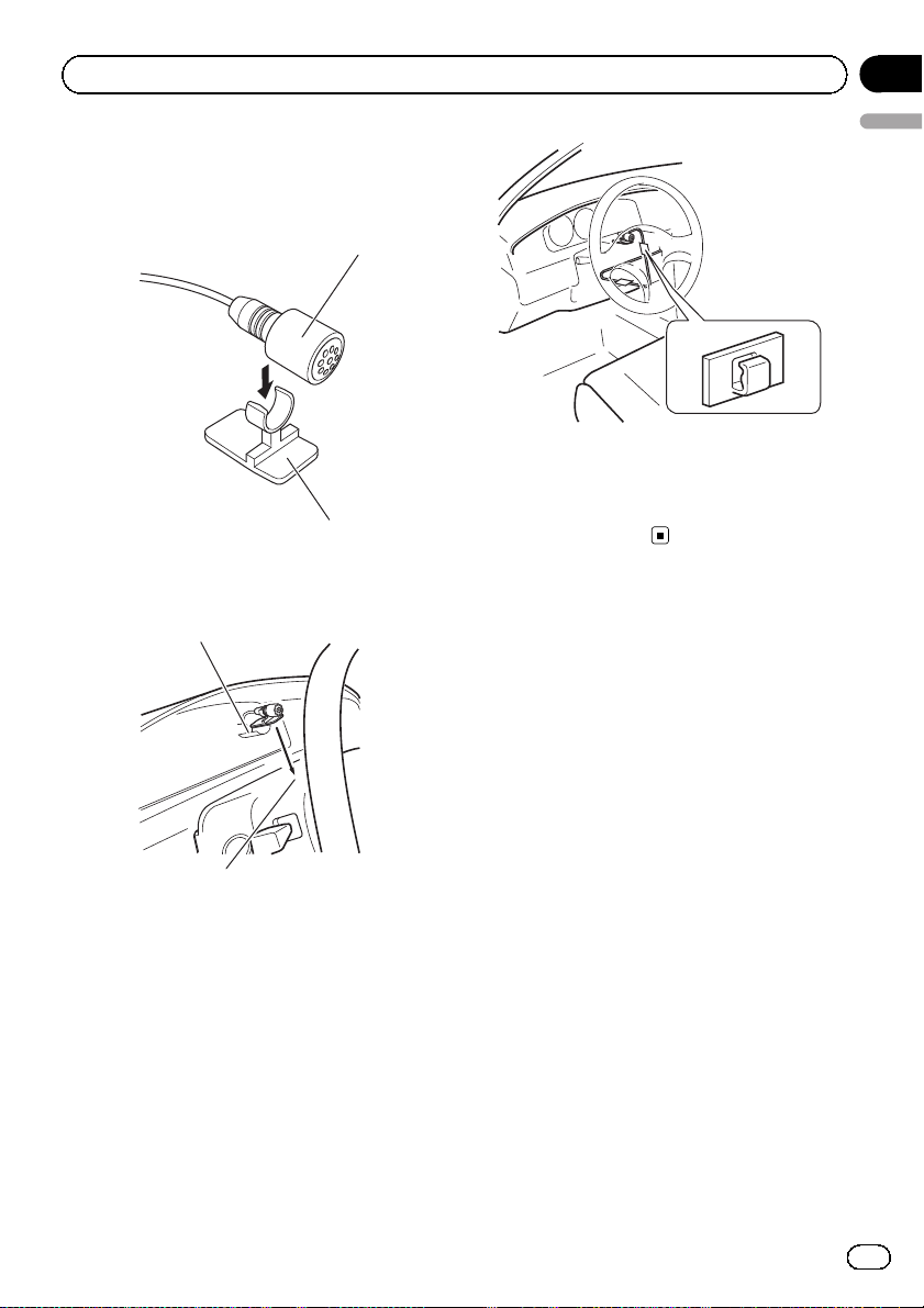
Installation
Installation on the steering column
1 Install the microphone in the microphone holder.
Microphone
Microphone holder
2 Mount the microphone on the steering
column.
Peel off the protective sheet on the rear.
Section
03
English
Clamps
Use separately sold
clamps to secure the
lead where necessary
inside the vehicle.
Install the microphone on the steering column, keeping it away from the steering
wheel.
Engb
21
Page 22
Section
04
After installation
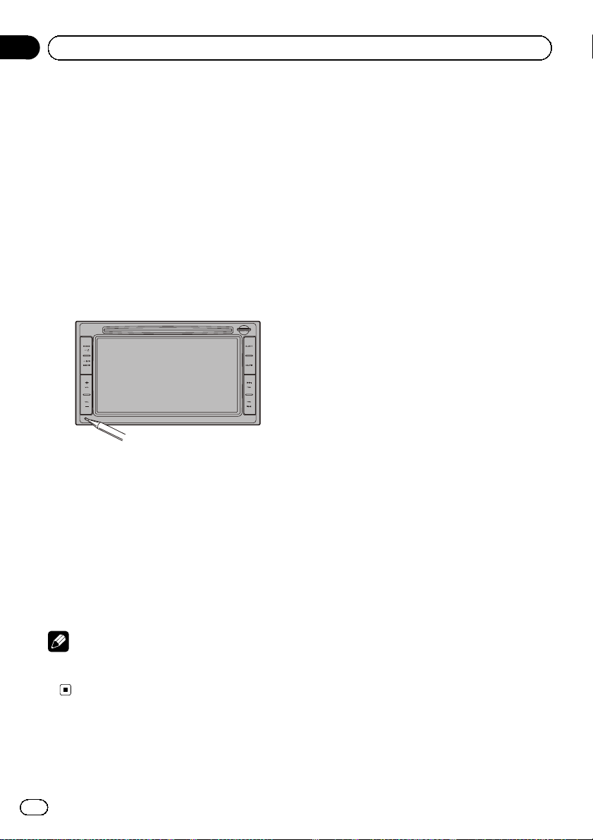
After installing this product
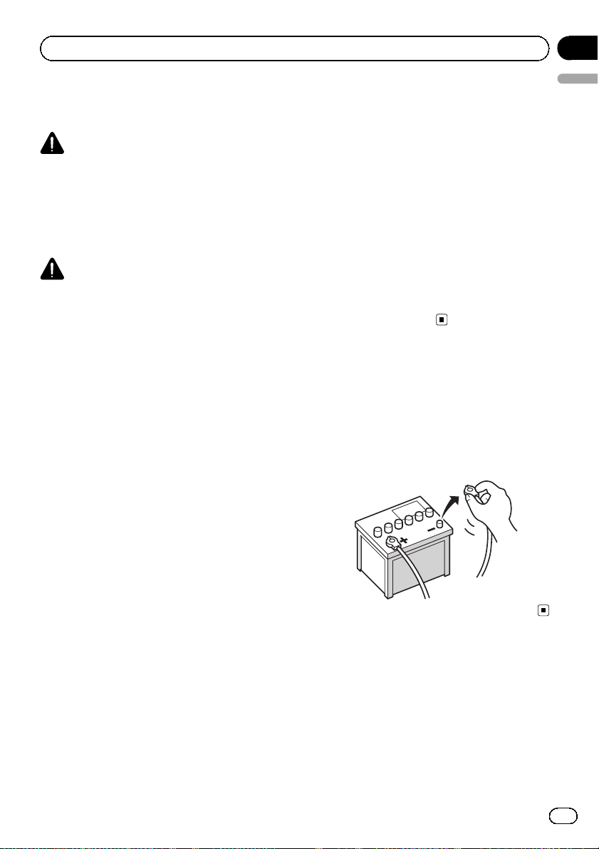
1 Reconnect the negative (–) terminal of
the vehicle’s battery.
First, double-check that all connections are
correct and that this product is installed correctly. Reassemble all vehicle components
that you previously removed. Then reconnect
the negative (–) cable to the negative ( –) terminal of the battery.
2 Start the engine.
3 Press the reset button.
Press the reset button on this product with a
pointed object such as the tip of a pen.
4 Make the following settings.
= For details concerning operations, refer to
Operation Manual.
1 Set the language.
2 Drive an unobstructed road until the GPS
starts receiving the signal normally.
3 Make some necessary adjustments.
! Setting the time
! Setting the units and the date format,
etc.
! Change other settings as you prefer
Note
After installing this product, be sure to check at a
safe place that the vehicle is performing normally.
22
Engb
Page 23
Sommaire
Français
Précautions
Votre nouveau système de navigation et ce
manuel 24
Importantes mesures de sécurité 24
Manipulation de la carte microSD 25
Branchement du système
Précautions à prendre avant de brancher le
système 26
Avant d’installer ce produit 26
Pour éviter toute détérioration 27
– Remarque concernant le fil bleu/
blanc 27
Pièces fournies 28
Branchement du système 30
Branchement du câble de ligne de
contrôle 32
Branchement d’un amplificateur de
puissance vendu séparément 33
Branchement d’une caméra de
rétrovisée 34
Branchement d’un élément vidéo
externe 35
– Utilisation d’une entrée AV (AUX) 35
– Utilisation d’une entrée AV (USB) 35
Branchement de l’écran arrière 36
– Utilisation d’un écran arrière raccordé
à la sortie vidéo arrière 36
– Installation en utilisant les trous de vis
sur les côtés de cette unité de
navigation 39
Installation de l’antenne GPS 40
– Remarques sur l’installation 40
– Pièces fournies 40
– Installation de l’antenne dans le
véhicule (sur le tableau de bord ou la
lunette arrière) 41
Installation du microphone 42
– Pièces fournies 42
– Installation sur le pare-soleil 42
– Installation sur la colonne de
direction 43
Après l’installation
Après avoir installé ce produit 44
Installation
Précautions à prendre avant
l’installation 37
Pour éviter les parasites
électromagnétiques 37
Avant de procéder à l’installation 38
Installation du système de navigation 38
– Remarques sur l’installation 38
– Pièces fournies 39
– Avant d’installer cette unité de
navigation 39
23
Fr
Page 24
Section
01
Précautions
Votre nouveau système de
navigation et ce manuel
! La fonction de navigation de ce produit (et
la caméra de rétrovisée en option le cas
échéant) est uniquement destinée à vous
assister lors de la conduite de votre véhicule. Elle n’autorise en aucun cas un relâchement de votre attention, de votre
jugement et de votre vigilance pendant la
conduite.
! N’utilisez jamais ce système de navigation
en cas d’urgence pour vous rendre à l’hôpital ou dans une station de police. Veuillez
le cas échéant appeler le numéro d’urgence du service concerné.
! N’utilisez pas ce système de navigation (ou
la caméra de rétrovisée en option le cas
échéant) si celui-ci risque d’une façon ou
d’une autre de détourner votre attention.
Observez toujours les règles de sécurité et
respectez toujours les réglementations de
la circulation routière en vigueur. Si vous
éprouvez des difficultés à utiliser le système ou à lire l’écran, garez votre véhicule
en lieu sûr et serrez le frein à main avant
d’effectuer les réglages nécessaires.
! Ce manuel explique comment installer le
système de navigation dans votre véhicule.
Le fonctionnement du système de navigation est expliqué dans les manuels séparés
du système de navigation.
! N’installez pas ce produit dans un endroit
où il risque (i) d’entraver la visibilité du
conducteur, (ii) d’altérer le fonctionnement
de certains systèmes de commande des
dispositifs de sécurité du véhicule, y
compris les airbags ou les touches de feux
de détresse, ou (iii) d’empêcher le conducteur de conduire le véhicule en toute sécurité. Dans certains cas, il peut ne pas être
possible d’installer ce produit en raison du
type de véhicule ou de la forme de l’intérieur du véhicule.
Importantes mesures de
sécurité
AVERTISSEMENT
Pioneer vous déconseille d’installer vousmême votre système de navigation. Ce produit est conçu pour une installation professionnelle uniquement. Nous vous
recommandons de confier l’installation uniquement à un personnel de service Pioneer
agréé, qui a été spécialement formé et est expérimenté en matière de systèmes électroniques mobiles, de montage et d’installation
de ce type de produit. NE TENTEZ JAMAIS
D’EFFECTUER VOUS-MÊME L’ENTRETIEN
OU DE DÉPANNER CE SYSTÈME DE NAVIGATION. L’installation ou l’entretien de ce
produit et des câbles de raccordement vous
expose à des décharges électriques ou autres
dangers, et risque de provoquer des détériorations du système de navigation non couvertes par la garantie.
! Lisez attentivement le contenu de ce ma-
nuel avant d’installer votre système de navigation.
! Conservez ce manuel à portée de main
pour vous y reporter ultérieurement.
! Tenez compte de tous les avertissements
formulés dans ce manuel et respectez soigneusement les consignes.
! Dans certaines circonstances, ce système
de navigation peut afficher des informations erronées sur la position de votre véhicule, la distance des objets affichés à
l’écran et les directions de la boussole. En
outre, le système comporte certaines limitations, notamment l’incapacité de signaler
les rues à sens unique, les restrictions temporaires à la circulation et les zones où la
circulation peut devenir dangereuse. Veuillez vous en remettre à votre bon jugement
en fonction des conditions réelles de
conduite.
24
Fr
Page 25
Précautions
! Comme tout autre accessoire de l’habita-
cle, le système de navigation ne doit pas
détourner votre attention ni nuire à la sécurité de la conduite sous peine d’entraîner
des blessures graves voire mortelles. Si
vous éprouvez des difficultés à utiliser le
système ou à lire l’écran, effectuez les réglages nécessaires après vous être garé
dans un endroit sûr.
! Veillez à toujours porter votre ceinture de
sécurité sur la route. En cas d’accident, le
port de la ceinture peut réduire considérablement la gravité des blessures.
! Certaines lois nationales ou gouvernemen-
tales peuvent interdire ou restreindre l ’emplacement et l’utilisation de ce système
dans votre véhicule. Veuillez vous conformer à toutes les lois et réglementations en
vigueur concernant l’utilisation, l’installation et le fonctionnement de votre système
de navigation.
Section
01
Français
Manipulation de la carte
microSD
Une carte microSD est installé dans la fente
de carte SD de ce système de navigation. En
l’absence de cette carte, le système de navigation ne pourra pas fonctionner correctement.
Ne pas enlever la carte microSD de la fente de
carte SD sauf en cas de mises à jour logicielles.
= Pour en savoir plus, consultez le Manuel de
fonctionnement.
25
Fr
Page 26
Section
02
Branchement du système
Précautions à prendre avant
de brancher le système
AVERTISSEMENT
N’essayez pas de modifier ou désactiver le
système de verrouillage du frein à main, lequel est installé pour votre protection. La modification ou la désactivation du système de
verrouillage du frein à main peut entraîner
des blessures graves, voire mortelles.
ATTENTION
! Si vous décidez de réaliser l’installation
vous-même, et possédez une expérience
spéciale en installation d’électronique automobile, veuillez suivre attentivement
toutes les étapes du manuel d’installation.
! Attachez tous les fils avec des colliers ou
des serre-câbles. Ne laissez aucun fil à nu.
! Ne raccordez pas directement le fil jaune
conducteur de ce produit à la batterie du
véhicule. Si ce fil conducteur est directement raccordé à la batterie, les vibrations
du moteur peuvent finir par user les câbles au niveau de la jonction avec l’habitacle et provoquer un défaut d’isolation. Si
l’isolation du fil conducteur jaune se déchire sous l’effet du contact avec des pièces métalliques, il peut en résulter un
court-circuit extrêmement dangereux.
! Il est extrêmement dangereux de laisser
les câbles s’enrouler autour de la colonne
de direction ou du levier de vitesse. Assurez-vous d’installer ce produit, ses câbles
et les fils de telle façon qu’ils n’obstruent
ni ne gênent la conduite.
! Veillez à ce que la trajectoire des câbles et
des fils n’interfère pas avec les pièces en
mouvement du véhicule. Fixez les câbles
de manière à les empêcher d’être happés
par, notamment, le volant, le levier de vitesse, le frein à main, les glissières de
siège, les portes, ou tout autre élément de
commande du véhicule.
! La trajectoire des fils ne doit pas être ex-
posée à des températures élevées. Si l’isolation chauffe, les fils risquent d’être
endommagés, ce qui peut entraîner un
court-circuit ou un dysfonctionnement, et
endommager de manière irrémédiable le
produit.
! Ne coupez pas le câble de l’antenne GPS
et n’utilisez pas de rallonge. Une telle modification pourrait provoquer un court-circuit ou un dysfonctionnement.
! Ne raccourcissez aucun fil conducteur.
Vous risqueriez autrement de provoquer
un dysfonctionnement du circuit de protection (porte-fusibles, résistance de fusible ou filtre, etc.).
! N’utilisez jamais le cordon d’alimentation
du système d’alimentation pour raccorder
d’autres appareils électriques. La capacité
du cordon serait dépassée, ce qui provoquerait une surchauffe.
Avant d’installer ce produit
! Utilisez cet appareil uniquement avec une
batterie de 12 V, avec pôle négatif à la
masse. Sinon, cela pourrait entraîner un incendie ou un mauvais fonctionnement.
! Afin d’éviter tout risque de court-circuit, dé-
branchez le câble de la borne négative (–)
de la batterie avant de commencer la pose.
26
Fr
Page 27
Branchement du système
Section
02
Pour éviter toute
détérioration
AVERTISSEMENT
! Utilisez des haut-parleurs de plus de 50 W
(valeur de sortie) et avec une impédance
comprise entre 4 W et 8 W.N’utilisez pas de
haut-parleurs 1 W à3W avec cet appareil.
! Le fil conducteur noir est mis à la masse.
Veuillez mettre à la masse ce fil conducteur séparément de la masse des produits
haute tension tels que les amplificateurs
de puissance. Ne reliez pas plus d’un produit à la masse d’un autre produit. Par
exemple, vous devez relier à la masse
chaque unité d’amplificateur séparément
de la masse de ce système de navigation.
Le fait de raccorder les masses ensemble
risque de provoquer un incendie et/ou
d’endommager les produits, si les fils de
masse se déconnectent.
! Lors du remplacement du fusible, veillez à
utiliser seulement un fusible du calibre indiqué sur ce produit.
! Pour débrancher un connecteur, tirez le
connecteur proprement dit et non son fil
pour éviter de l’arracher.
! Ce produit ne peut pas être installé dans
un véhicule qui ne possède pas de position
ACC (accessoire) sur le commutateur d’al-
lumage.
C
C
A
O
F
N
F
O
Position ACC Pas de position
S
T
A
R
T
! Pour éviter les courts-circuits, recouvrez les
fils déconnectés de ruban isolant. Il est particulièrement important d’isoler tous les fils
conducteurs de haut-parleurs non utilisés
pour éviter tout risque de court-circuit.
O
F
N
F
O
ACC
S
T
A
R
T
! Raccordez les connecteurs de même cou-
leur au port de couleur correspondant,
c’est-à-dire le connecteur bleu au port bleu,
le noir au noir, etc.
! Pour raccorder l’amplificateur de puis-
sance à d’autres unités, veuillez vous reporter au mode d’emploi concerné.
! Un circuit BPTL unique étant employé, ne
reliez pas directement l’extrémité du fil
conducteur de haut-parleur * ou ne reliez
pas les extrémités des fils conducteurs de
haut-parleur * ensemble. Veillez à relier
l’extrémité * du fil conducteur de haut-parleur à l’extrémité * du fil conducteur de
haut-parleur de ce système de navigation.
! Si la fiche femelle RCA de ce produit n’est
pas utilisée, ne retirez pas les capuchons
fixés à l’extrémité du connecteur.
Remarque concernant le fil
bleu/blanc
! Lorsque le commutateur d’allumage est
sur Marche (ACC ON), un signal de
commande est émis par le biais du fil bleu/
blanc. Raccordez-le à une borne de
commande à distance du système d’amplificateur de puissance externe, à la prise de
commande de relais de l’antenne automatique du véhicule ou au terminal de
commande d’alimentation de l’amplificateur d’antenne (max. 300 mA 12 VCC). Le signal de commande est émis par le biais du
fil bleu/blanc, même si la source audio est
désactivée.
! Assurez-vous de ne pas utiliser ce fil
comme câble d’alimentation pour les amplificateurs de puissance externes. Une
telle connexion pourrait causer un appel de
courant excessif et un mauvais fonctionnement.
Français
27
Fr
Page 28
Section
02
Branchement du système
! Assurez-vous de ne pas utiliser ce fil
comme câble d’alimentation pour l’antenne automatique ou l’amplificateur d’antenne. Une telle connexion pourrait causer
un appel de courant excessif et un mauvais
fonctionnement.
Pièces fournies
Unité de navigation Câble de ligne de
Cordon du connecteur
AV
Antenne GPS
contrôle
Microphone
28
Fr
Page 29

Branchement du système
Section
02
Français
29
Fr
Page 30
Section
02
Branchement du système
Branchement du système
Unité de navigation
12cm
(*1)
Cordon d’alimentation
Pour la connexion, reportez-vous
au manuel sur le câblage et
l’installation fourni séparément.
(*1)
Assurez-vous que les trois connecteurs, jaune, vert et bleu sont installés
avant de procéder à la connexion du système.
(*2)
Branchez le câble d’interface USB pour l’iPod ou un périphérique de
stockage USB compatible.
(*3)
Vous avez besoin des deux connexions pour connecter votre iPod.
(*4)
Pour en savoir plus sur leur fonctionnement et la compatibilité, reportez-vous
au Manuel de fonctionnement.
Fusible (15A)
Antenne véhicule
Câble de ligne de contrôle
25cm
Entrée télécommande câblée (SWC)
Veuillez vous reporter au manuel d’instructions pour l’adaptateur
de télécommande câblée.
Prise pour microphone (MIC)
12cm
12cm
30
Fr
Page 31

Branchement du système
3m
4m
Câble AV
(iPod/AV IN)
Section
02
Antenne GPS
Français
Microphone
Câble USB
(vendu séparément)
(*4)
Câble d’interface
USB pour iPod
(vendu séparément)
Câble AV
(vendu
séparément)
(*2)
(*3)
Port Dock
Connector
iPod ou iPhone
AVERTISSEMENT
· Pour éviter tout accident ainsi qu’une infraction potentielle aux lois applicables,
ce produit ne doit jamais être utilisé pendant la conduite d’un véhicule sauf à des
fins de navigation. Les écrans arrière ne doivent pas être placés à des endroits qui
pourraient distraire les conducteurs.
· Dans certains pays, le fait de regarder une Image vidéo sur un afficheur dans une
voiture est illégal, même s’il s’agit d’autres personnes que le conducteur.
Lorsqu’il existe de telles règles, vous devez vous y conformer et ne pas utiliser la
vidéo de ce produit.
31
Fr
Page 32

Section
02
Branchement du système
Branchement du câble de ligne de contrôle
Câble de ligne de contrôle
Vert/blanc (BRAKE)
Ce raccordement est utilisé pour détecter le
statut de MARCHE/ARRÊT du frein à main. Ce
fil doit être raccordé au côté alimentation
électrique du contacteur du frein à main.
Si ce raccordement est effectué
incorrectement ou n’est pas effectué,
certaines fonctions du produit seront
inutilisables.
Remarque
La position du contacteur du frein à main
varie selon du modèle du véhicule. Pour de
plus de détails, contactez votre revendeur
Pioneer agréé ou un installateur
professionnel.
Rose (REVERSE)
Ce raccordement permet au produit de détecter si le
véhicule avance ou recule. Raccordez le fil rose au
câble dont la tension change lorsque la marche
arrière est enclenchée. Sans ce raccordement, le
capteur risque de ne pas pouvoir détecter
correctement le déplacement en marche
avant/arrière de votre véhicule, et par conséquent la
position de votre véhicule telle qu’elle est détectée
par le capteur risque de ne pas correspondre à votre
position réelle.
Remarque
Lors de l’utilisation d’une caméra de rétrovisée,
assurez-vous de raccorder ce fil. En l’absence de
raccordement, vous ne pourrez pas passer à
l’image de la caméra de rétrovisée.
Unité de navigation
AVERTISSEMENT
LE FIL VERT/BLANC DU CONNECTEUR
D’ALIMENTATION EST CONÇU POUR DÉTECTER
L’ÉTAT DE STATIONNEMENT ET DOIT ÊTRE BRANCHÉ
CÔTÉ ALIMENTATION ÉLECTRIQUE DU CONTACTEUR
DE FREIN À MAIN. UNE CONNEXION OU UNE
UTILISATION INAPPROPRIÉE DE CE FIL PEUT ÊTRE
ILLÉGALE À L’ÉGARD DE LA LOI EN VIGUEUR ET
RISQUE D’ENTRAÎNER DES BLESSURES SÉRIEUSES
OU DES DOMMAGES.
Méthode de raccordement
Fixez le fil du côté alimentation
électrique du contacteur du frein à
main avec un serre-câble.
Fixez solidement avec des pinces à
becs fins.
32
Fr
Côté alimentation électrique
Côté terre
Contacteur du frein à main
Page 33

Branchement du système
Branchement d’un amplificateur de puissance vendu
séparément
Unité de navigation
Section
02
Français
Cordon du
connecteur AV
Câble de ligne de contrôle
Bleu/blanc (P.CONT)
Vers borne de commande
système de l’amplificateur de
puissance (max. 300mA
12 VCC).
Connectez à la borne de la ligne
d’alimentation (vendue séparément)
ce qui est équivalent à P.CONT.
Rouge
(FULL/SW)
Droite
Haut-parleur
arrière ou
d’extrêmes graves
Blanc
(FULL/SW)
Gauche
Câbles RCA
(vendus séparément)
Amp. Puissance
(vendu séparément)
Commande à distance du
système
Haut-parleur arrière
ou d’extrêmes
graves
Remarque
Vous pouvez changer la sortie RCA du haut-parleur d’extrêmes graves en
fonction de votre système de haut-parleur d’extrêmes graves. (Voir le manuel de
fonctionnement.)
33
Fr
Page 34

Section
02
Branchement du système
Branchement d’une caméra
de rétrovisée
Quand ce produit est utilisé avec une caméra
de rétrovisée, il est possible de commuter automatiquement entre le signal vidéo et l’image
de rétrovisée quand le levier de vitesse est
placé sur la position REVERSE (R). Le mode
Caméra arrière vous permet également de vérifier ce qu’il y a derrière le véhicule quand
vous conduisez.
p Pour en savoir plus, consultez le Manuel de
fonctionnement.
AVERTISSEMENT
UTILISEZ L’ENTRÉE UNIQUEMENT POUR LA
MARCHE ARRIÈRE OU L’IMAGE INVERSÉE DE
LA CAMÉRA DE RÉTROVISÉE. TOUTE AUTRE
UTILISATION PEUT ENTRAÎNER DES BLESSURES CORPORELLES OU UNE DÉTÉRIORATION
DE L’APPAREIL.
ATTENTION
! L’image de l’écran peut apparaître inversée.
! La caméra de rétrovisée est à utiliser en tant
qu’aide pour surveiller une caravane, ou pour
se garer en marche arrière dans un emplacement de parking un peu étroit. N’utilisez pas
cette fonction dans un but de divertissement.
! Les objets dans la caméra de rétrovisée peu-
vent paraître plus proches ou plus éloignés
qu’en réalité.
! Veuillez noter que la zone de l’image affichée
par la caméra de rétrovisée peut légèrement
différer selon que les images plein écran sont
affichées en marche arrière, ou que vous vérifiez ce qui se passe à l’arrière du véhicule en
marche avant.
Unité de navigation
Câble de ligne de
contrôle
Jaune
(CAMERA VIDEO)
Rose
(REVERSE)
Câble RCA
Caméra de rétrovisée
(par ex. ND-BC6)
(vendue séparément)
Pour en savoir plus à propos des raccordements, reportez-vous à la page 32, Branchement du câble de
ligne de contrôle.
Remarque
Ne branchez que le système de navigation sur
la caméra de rétrovisée. N’y raccordez aucun
autre appareil.
34
Fr
Page 35

Branchement du système
Section
02
Branchement d’un élément
vidéo externe
Utilisation d’une entrée AV (AUX)
Unité de navigation
Câble AV
(iPod/AV IN)
Câble AV
(vendu séparément)
Câble AV mini-jack
(CD-RM10)
(vendu séparément)
Jaune
ATTENTION
Veillez à utiliser un câble AV mini-jack (CD-RM10)
(vendu séparément) pour le raccordement. Si
vous utilisez un autre type de câble, la position
du raccordement pourrait différer, entraînant une
déformation du son et des images.
OK
L : Audio gauche (Blanc)
L
GVR
Utilisation d’une entrée AV (USB)
Unité de navigation
R : Audio droite (Rouge)
L
V : Vidéo (Jaune)
GRV
G : Masse
Français
Vers sortie
vidéo
Élément vidéo
externe
(vendu séparément)
Blanc, rouge
Câbles RCA
(vendus
séparément)
Vers sorties audio
Câble USB
(vendu
séparément)
Périphérique de stockage USB
35
Fr
Page 36

Section
02
Branchement du système
Branchement de l’écran arrière
Unité de navigation
Lors du raccordement d'un
écran arrière avec entrée
Cordon du
connecteur AV
Jaune
Câble RCA
(vendu
séparément)
Vers entrée
vidéo
RCA audio
Blanc, rouge
Câble RCA
(vendu
séparément)
Vers entrée audio
Utilisation d’un écran arrière
raccordé à la sortie vidéo arrière
AVERTISSEMENT
NE JAMAIS installer l’écran arrière dans un
endroit permettant au conducteur de regarder la source vidéo en conduisant.
La sortie vidéo arrière de ce système de navigation est destinée au branchement d’un écran permettant aux passagers des sièges arrière de
regarder la source vidéo.
36
Écran arrière avec
prises entrée RCA
Fr
Page 37

Installation
Section
03
Précautions à prendre
avant l’installation
ATTENTION
! Ne jamais installer ce produit dans un en-
droit ou de telle sorte qu’il :
— risque de blesser le conducteur ou les
passagers en cas d’arrêt brusque.
— puisse interférer avec les commandes
de manœuvre du conducteur tel que
sur le plancher, en face du siège
conducteur, ou à proximité du volant
ou du levier de vitesse.
! Assurez-vous que rien ne se trouve der-
rière le tableau de bord ou une cloison
avant d’y percer des trous. Veillez à ne pas
endommager les tubulures de carburant
et de frein, les composants électroniques,
les câbles de communication ou d’alimentation.
! Si vous utilisez des vis, veillez à ce qu’el-
les n’entrent pas en contact avec un fil
conducteur électrique. Les vibrations peuvent endommager les fils ou l’isolation, en
entraînant un court-circuit ou d’autres
dommages sur le véhicule.
! Pour garantir une installation correcte, as-
surez-vous d’utiliser les pièces fournies de
la façon spécifiée. Si certaines pièces ne
sont pas fournies avec cet appareil, utilisez des pièces compatibles de la façon
spécifiée après avoir fait vérifier la compatibilité par votre revendeur. Si d’autres
pièces que les pièces fournies ou compatibles sont utilisées, elles peuvent endommager les pièces internes de ce produit ou
être mal assujetties, et le produit peut se
détacher.
! Il est extrêmement dangereux de laisser
les câbles s’enrouler autour de la colonne
de direction ou du levier de vitesse. Assurez-vous d’installer ce produit, ses câbles
et les fils de telle façon qu’ils n’obstruent
ni ne gênent la conduite.
! Assurez-vous qu’aucun fil conducteur ne
puisse se coincer dans une porte ou le mé-
canisme de coulissement d’un siège, car
ceci pourrait provoquer un court-circuit.
! Vérifiez le bon fonctionnement des autres
équipements du véhicule après l’installation du système de navigation.
! N’installez pas ce système de navigation
dans un endroit où il risque (i) d’entraver
la visibilité du conducteur, (ii) d’altérer le
fonctionnement de certains systèmes de
commande ou dispositifs de sécurité du
véhicule, y compris les airbags ou les touches de feux de détresse, ou (iii) d’empêcher le conducteur de conduire le véhicule
en toute sécurité.
! Installez le système de navigation entre le
siège conducteur et le siège passager
avant afin qu’il ne puisse pas être percuté
par le conducteur ou le passager avant en
cas de freinage brusque.
! N’installez jamais le système de naviga-
tion devant ou à côté d’un endroit sur le
tableau de bord, une portière ou un pilier,
à partir duquel un des airbags du véhicule
doit se déployer. Veuillez vous reporter au
mode d’emploi du véhicule pour en savoir
plus sur les zones de déploiement des airbags frontaux.
! Des blessures graves voire mortelles peu-
vent découler du non-respect de ces précautions.
Pour éviter les parasites
électromagnétiques
Pour éviter toute interférence, placez les éléments suivants le plus loin possible de ce système de navigation, d’autres câbles ou de fils
conducteurs :
! Antenne FM, PO/GO et son fil conducteur
! Antenne GPS et son fil conducteur
Français
37
Fr
Page 38

Section
03
Installation
De plus, vous devez placer ou acheminer le fil
d’antenne aussi loin que possible des autres
fils d’antenne. Ne les attachez, ne les placez
ou ne les acheminez pas ensemble, ni ne les
croisez. Le bruit électromagnétique augmentera les risques d’erreurs d’affichage de l’emplacement du véhicule.
Avant de procéder à
l’installation
! Consultez le concessionnaire le plus pro-
che si l’installation nécessite de percer des
trous ou toute autre modification du véhicule.
! Avant d’installer ce produit définitivement,
connectez le câblage provisoirement pour
vous assurer que les connexions sont correctes et que le système fonctionne
normalement.
Installation du système de
navigation
Remarques sur l’installation
! N’installez pas le système de navigation
dans un endroit soumis à des températures
élevées ou à l’humidité. Par exemple :
— À proximité du chauffage, de la ventila-
tion ou de la climatisation.
— En plein soleil, comme sur le dessus du
tableau de bord.
— Endroits susceptibles d’être exposés à
la pluie, près de la portière ou sur le
plancher du véhicule par exemple.
! Installez ce système de navigation dans
une zone suffisamment solide pour supporter son poids. Choisissez un endroit où le
système de navigation puisse être fixé de
manière sûre et installez-le solidement.
Une mauvaise fixation du système de navigation peut entraîner un dysfonctionnement de la localisation du véhicule.
! Installez l’unité de navigation horizontale-
ment sur une surface avec une tolérance
de 0 à 30 degrés (dans une plage de 5 degrés vers la gauche ou la droite). Une mauvaise installation de l’unité avec une
inclinaison de la surface supérieure à cette
marge de tolérance risque d’accroître le potentiel d’erreurs dans l’affichage de l’emplacement, et de réduire les performances
d’affichage.
30°
5° 5°
! Lors de l’installation de l’appareil, laissez
suffisamment d’espace derrière le panneau
arrière pour permettre une dissipation correcte de la chaleur et enroulez tout câble
gênant de façon qu’il n’obstrue pas les orifices de ventilation.
Laissez suffisamment
d’espace
5 cm
5 cm
38
Fr
Page 39

Installation
Section
03
! Les câbles ne doivent pas traverser la zone
indiquée dans la figure ci-dessous, afin que
la chaleur dégagée par les amplificateurs
et le mécanisme de navigation puisse se
dissiper librement.
Ne pas couvrir cette zone.
! Une surchauffe peut provoquer la détério-
ration de la diode laser. Évitez donc d’installer l’unité de navigation à proximité d’une
source de chaleur, une bouche d’air par
exemple.
Pièces fournies
1 Retirez les deux boulons d’expédition.
Français
2 Bouchez les deux trous des vis avec du
ruban adhésif fourni avec l’unité de navigation.
Ruban adhésif
Unité de navigation Ruban adhésif
Vis à tête bombée
(5 mm × 6mm)
(6 pièces)
(2 pièces)
Vis à tête plate
(5 mm × 7 mm)
(6 pièces)
Avant d’installer cette unité de
navigation
ATTENTION
Le lecteur de disque ne fonctionnera pas correctement si vous ne retirez pas les deux
boulons de l’unité de navigation. Si vous utilisez le lecteur de disque avec les boulons,
des problèmes peuvent survenir.
Installation en utilisant les
trous de vis sur les côtés de
cette unité de navigation
% Fixation de l’unité de navigation dans
le tiroir de l’autoradio.
Positionnez l’unité de navigation de manière à
ce que les trous de vis soient alignés avec les
trous de vis de la console, et serrez trois vis de
chaque côté.
Fr
39
Page 40

Section
03
Installation
Si le cliquet gêne l’installation, vous
pouvez le plier pour dégager l’espace.
Support de montage radio de l’usine
Vis à tête bombée ou
vis à tête plate
Utilisez toujours les
vis fournies avec ce
système de
navigation.
Tableau de bord ou
console
Remarques sur l’installation
! L’antenne doit être installée sur une sur-
face plane bien réceptive aux ondes radio.
Les ondes radio ne peuvent pas être captées correctement par l’antenne si la réception des satellites est gênée.
Tableau de bord Lunette arrière
! Ne tirez pas le fil pour retirer l’antenne
GPS. Celle-ci est fixée à l’aide d’un aimant
très puissant. Vous risqueriez d’arracher le
fil.
! Aucune peinture ne doit être appliquée sur
l’antenne GPS afin de ne pas réduire ses
performances.
Installation de l’antenne GPS
ATTENTION
Ne coupez pas le fil d’antenne GPS pour le
raccourcir et n’utilisez pas d’extension pour
le rallonger. Le fait d’intervenir sur le câble
d’antenne risque d’entraîner un court-circuit
ou un dysfonctionnement et d’endommager
de manière irrémédiable le système de navigation.
40
Fr
Pièces fournies
Antenne GPS Bande adhésive à
double face
Page 41

Installation
Installation de l’antenne dans le véhicule (sur le tableau de bord
ou la lunette arrière)
AVERTISSEMENT
N’installez pas l’antenne GPS par dessus un capteur ou une bouche d’air du tableau de bord du
véhicule, car cela pourrait perturber le fonctionnement normal du capteur ou de la bouche d’air
et compromettre la capacité de la bande adhésive à double face sous l’antenne GPS d’assurer
une fixation correcte et sûre sur le tableau de bord.
Fixez la bande adhésive à double face sur une
surface aussi plate que possible située de manière que l’antenne GPS soit orientée vers une
vitre. Posez l’antenne GPS sur la bande adhésive à double face.
Bande adhésive à double face
Décollez le feuillet de protection.
Antenne GPS
Assurez-vous que la surface ne
présente pas d’humidité, de
poussière, de saleté, d’huile ou
autre avant d’y fixer la bande
adhésive à double face.
Remarque
La bande adhésive à double
face est pourvu d’une bande
adhésive résistante,
susceptible de laisser une
marque sur la surface
lorsqu’elle est retirée.
Section
03
Français
Remarque
Les vitres de certains modèles de véhicules ne
laissent pas passer les signaux des satellites
GPS. Dans ce cas, installez l’antenne GPS à
l’extérieur du véhicule.
Serre-fils
Utilisez des serre-fils vendus séparément pour
fixer le fil conducteur aux endroits nécessaires
dans le véhicule.
41
Fr
Page 42

Section
03
Installation
Installation du microphone
! Installez le microphone dans un endroit
permettant une bonne réception de la voix
du conducteur.
! Éteignez le système de navigation (ACC
OFF) avant de connecter le microphone.
Pièces fournies
Microphone Agrafe pour micro
Porte-microphone
Installation sur le pare-soleil
1 Installez le microphone dans l’agrafe
pour micro.
Microphone
2 Fixez l’agrafe pour micro au pare-soleil.
Agrafe pour micro
Serre-fils
Utilisez des serre-fils vendus séparément pour
fixer le fil conducteur aux endroits nécessaires
dans le véhicule.
Installez le microphone sur le pare-soleil lorsqu’il est en position relevée. La reconnaissance vocale est impossible lorsque le paresoleil est en position abaissée.
42
Agrafe pour micro
Fr
Page 43

Installation
Installation sur la colonne de
direction
1 Installez le microphone sur le porte-microphone.
Microphone
Porte-microphone
2 Montez le microphone sur la colonne
de direction.
Décollez le feuillet de protection sur l’arrière.
Section
03
Français
Serre-fils
Utilisez des serre-fils
vendus séparément
pour fixer le fil conducteur aux endroits nécessaires dans le
véhicule.
Installez le microphone sur la colonne de direction, à distance du volant.
43
Fr
Page 44

Section
04
Après l’installation
Après avoir installé ce produit
1 Raccordez à nouveau la borne négative
(–) de la batterie du véhicule.
Vérifiez une nouvelle fois que toutes les connexions ont été bien faites et que ce produit est
correctement installé. Remettez en place les
éléments démontés du véhicule, puis rebranchez le câble négatif (–) sur la borne négative
(–) de la batterie.
2 Mettez le moteur en marche.
3 Appuyez sur le bouton de réinitialisation.
Avec la pointe d’un stylo-bille par exemple, appuyez sur le bouton de réinitialisation de ce
produit.
4 Faites les réglages suivants.
= Pour en savoir sur leur fonctionnement, re-
portez-vous au Manuel de fonctionnement.
1 Réglez la langue.
2 Roulez sur une route sans obstacle jusqu’à
ce que le GPS commence à recevoir le si-
gnal normalement.
3 Réalisez les réglages nécessaires.
! Réglage de l’heure
! Réglages des unités, du format de la
date, etc.
! Changez les autres réglages selon vos
préférences
Remarque
Une fois l’installation terminée, vérifiez le bon
fonctionnement du véhicule dans un endroit
sécurisé.
44
Fr
Page 45

Sommario
Precauzioni
Il nuovo sistema di navigazione e il presente
manuale 46
Misure di sicurezza importanti 46
Gestione della scheda microSD 47
Collegamento del sistema
Precauzioni prima di collegare il sistema 48
Prima di installare questo prodotto 48
Per evitare danni 49
– Informazione sul cavetto blu/
bianco 49
Parti in dotazione 50
Collegamento del sistema 52
Collegamento del cavo della linea di
controllo 54
Quando si effettua il collegamento a un
amplificatore in vendita
separatamente 55
Quando si effettua il collegamento a una
telecamera di visione posteriore 56
Quando si collega il componente video
esterno 57
– Uso di un ingresso AV (AUX) 57
– Uso di un ingresso AV (USB) 57
Quando si collega il display posteriore 58
– Quando si utilizza un display posteriore
collegato a un’uscita video
posteriore 58
– Installazione usando i fori delle viti sul
lato dell’unità di navigazione 61
Installazione dell’antenna GPS 62
– Note sull’installazione 62
– Parti in dotazione 62
– Quando si installa l’antenna all’interno
del veicolo (sul cruscotto o sul piano
portaoggetti posteriore) 63
Installazione del microfono 64
– Parti in dotazione 64
– Montaggio sul parasole 64
– Installazione sulla colonna di
sterzo 65
Dopo l’installazione
Dopo l’installazione del prodotto 66
Italiano
Installazione
Precauzioni prima dell’installazione 59
Per evitare disturbi elettromagnetici 59
Prima dell’installazione 60
Installazione del sistema di navigazione 60
– Note sull’installazione 60
– Parti in dotazione 61
– Prima di installare l’unità di
navigazione 61
45
It
Page 46

Sezione
01
Precauzioni
Il nuovo sistema di
navigazione e il presente
manuale
! Le caratteristiche di navigazione di questo
prodotto (e la telecamera di visione posteriore, se acquistata) sono da considerare
soltanto come un ausilio alla conduzione
del proprio veicolo. Non devono mancare
attenzione, giudizio e cautela del conducente durante la guida.
! Non utilizzare mai il sistema di navigazione
per raggiungere ospedali, stazioni di polizia
o altre destinazioni simili in un’emergenza.
Chiamare l’apposito numero di emergenza.
! Il sistema di navigazione (o la telecamera
di visione posteriore opzionale, se acquistata) non deve essere usato qualora ciò
possa in qualunque modo distrarre l’attenzione del conducente dalla guida in sicurezza del veicolo. È necessario osservare
sempre le regole per la guida in sicurezza e
seguire scrupolosamente la segnaletica
stradale esistente. In caso di difficoltà nell’uso del sistema o nella lettura dello schermo, per prima cosa arrestare il veicolo in
un luogo sicuro, innestare il freno di stazionamento e solo allora procedere con le necessarie regolazioni.
! Questo manuale illustra l’installazione del
sistema di navigazione nel veicolo. Il funzionamento del sistema di navigazione è illustrato negli altri manuali del sistema
stesso.
! Non installare questo prodotto dove può (i)
ostruire la visione del conducente, (ii) compromettere le prestazioni di un qualunque
sistema operativo sul veicolo o le funzioni
di sicurezza, inclusi airbag, pulsanti delle
luci di emergenza oppure (iii) compromettere la capacità del conducente di condurre
in sicurezza il veicolo. In alcuni casi, è possibile che non si possa installare questo
prodotto a causa del tipo di veicolo o della
forma dell’interno del veicolo.
Misure di sicurezza importanti
AVVERTENZA
Pioneer raccomanda di non installare personalmente il sistema di navigazione. Questo
prodotto è progettato per essere installato
esclusivamente da tecnici specializzati. Consigliamo che solo il personale di manutenzione autorizzato Pioneer, dotato di
addestramento speciale ed esperienza nell’elettronica mobile, si occupi del montaggio e
dell’installazione di questo prodotto. NON
TENTARE MAI DI ESEGUIRE PERSONALMENTE LA MANUTENZIONE DI QUESTO
PRODOTTO. L’installazione o la manutenzio-
ne di questo prodotto e dei suoi cavi di collegamento può esporre al rischio di scosse
elettriche o altri pericoli, e può causare danni
al sistema di navigazione che non sono coperti da garanzia.
! Leggere completamente e con attenzione
questo manuale prima di installare il sistema di navigazione.
! Conservare questo manuale a portata di
mano per riferimenti futuri.
! Fare attenzione a tutti gli avvertimenti in
questo manuale e seguire attentamente le
istruzioni.
! Questo sistema di navigazione può in alcu-
ni casi visualizzare informazioni non precise sulla posizione del veicolo, la distanza
degli oggetti mostrati sullo schermo e le direzioni della bussola. Inoltre il sistema ha
alcuni limiti inerenti, come l’incapacità di
individuare vie a senso unico, limitazioni
temporanee del traffico e zone di guida potenzialmente pericolose. Usare il proprio
giudizio in base alle condizioni di guida effettive.
46
It
Page 47

Precauzioni
! Come per altri accessori all’interno del vei-
colo, il sistema di navigazione non deve distrarre il conducente da una guida sicura
del veicolo, poiché potrebbero verificarsi incidenti con conseguenti lesioni gravi o
morte del conducente. Se si hanno difficoltà nel controllo del sistema o nella lettura
dello schermo, eseguire le regolazioni dopo
aver parcheggiato in un luogo sicuro.
! Ricordare di allacciare sempre la cintura di
sicurezza durante l’uso dell’automobile. In
caso di incidenti, le lesioni possono essere
molto più gravi se la cintura di sicurezza
non è allacciata correttamente.
! Le legislazioni di alcuni Paesi e governi
possono impedire o limitare il montaggio e
l’uso di questo sistema nel veicolo. Conformarsi a tutte le leggi e i regolamenti applicabili riguardo ad uso, installazione e
funzionamento del sistema di navigazione.
Sezione
01
Italiano
Gestione della scheda microSD
Una scheda microSD è installata nello slot per
scheda SD di questo sistema di navigazione.
Senza una scheda microSD, il sistema di navigazione non può funzionare correttamente.
Non rimuovere la scheda microSD dallo slot
per scheda SD, tranne che durante gli aggiornamenti del software.
= Per i dettagli, vedere il Manuale di funzio-
namento.
47
It
Page 48

Sezione
02
Collegamento del sistema
Precauzioni prima di
collegare il sistema
AVVERTENZA
Non manomettere in alcun modo o disabilitare il sistema di interblocco di sicurezza del
freno a mano che è necessario per proteggere
il conducente. In caso di manomissione o disabilitazione di tale sistema, è possibile che
incidenti con conseguenti lesioni gravi o
morte del conducente.
ATTENZIONE
! Se si decide di eseguire l’installazione da
soli e si ha particolare addestramento ed
esperienza nelle installazioni elettroniche
mobili, è necessario seguire attentamente
tutti i passi indicati nel manuale d’installazione.
! Fissare tutti i fili con morsetti per cavi o
nastro isolante. Non lasciare esposto
alcun filo nudo.
! Non collegare direttamente il cavo giallo
di questo prodotto alla batteria del veicolo. Se il cavo viene collegato direttamente
alla batteria, le vibrazioni del motore possono causare il cedimento dell’isolamento
nel punto in cui il cavo passa dall’abitacolo al vano motore. Se l’isolamento del
cavo giallo si lacera, il contatto con le
parti metalliche può causare cortocircuiti,
con corrispondenti gravi pericoli.
! I cavi potrebbero costituire una seria fonte
di pericolo qualora si attorcigliassero alla
colonna dello sterzo o alla leva del cambio. L’apparecchio, i relativi cavi e ogni
altro collegamento devono essere sistemati in modo che non ostruiscano o impediscano la guida in sicurezza del veicolo.
! Assicurarsi che i cavi e i fili non interferi-
scano o rimangano impigliati in una qualsiasi delle parti mobili del veicolo,
specialmente il volante, la leva del cambio, il freno a mano, le guide di scorrimento dei sedili, le porte e qualunque
comando del veicolo.
! Non posare i fili lungo percorsi in cui risul-
tano esposti a temperature elevate. Se l’isolamento si scalda, il filo può
danneggiarsi e causare cortocircuiti o
malfunzionamenti e danni permanenti al
prodotto.
! Non tagliare il cavo dell’antenna GPS per
accorciarlo e non usare una prolunga per
allungarlo. Un’alterazione del cavo dell’antenna può causare un cortocircuito.
! Non accorciare alcun cavo. Facendolo, il
circuito di protezione (portafusibile, resistore fusibile o filtro, ecc.) potrebbe non
funzionare più correttamente.
! Mai alimentare altri prodotti elettronici ta-
gliando l’isolamento del cavo di alimentazione del sistema di navigazione e
attingendo al cavo. La capacità di corrente
del cavo verrebbe ecceduta, causando surriscaldamenti.
Prima di installare questo
prodotto
! Utilizzare questa unità solo con una batte-
ria da 12 volt e una messa a terra negativa.
Se queste specifiche non verranno rispettate, potrebbe scaturirne un incendio o un
malfunzionamento.
! Per evitare cortocircuiti nell’impianto elet-
trico, accertarsi di scollegare il cavo della
batteria (–) prima di iniziare l’installazione.
48
It
Page 49

Collegamento del sistema
Sezione
02
Per evitare danni
AVVERTENZA
! Utilizzare diffusori con potenza superiore
a 50 W (valore di uscita) e tra 4 W e8W (va-
lore di impedenza). Non utilizzare diffusori con valori tra 1 W e3W per questa unità.
! Il cavo nero è il cavo di terra. Si prega di
eseguire la messa a terra di questo cavo
separatamente dalla messa a terra di prodotti a corrente elevata, come gli amplificatori di alimentazione. Non mettere a
massa un prodotto insieme alla messa a
terra di un altro prodotto. Per esempio, si
deve mettere a massa separatamente ciascuna unità amplificatore a una certa distanza dalla massa del sistema di
navigazione. Collegando le masse insieme si può causare un incendio e/o danni
ai prodotti se le loro masse si staccano.
! Quando si sostituisce il fusibile, assicurar-
si di usare soltanto un fusibile con le caratteristiche prescritte per questo
prodotto.
! Quando si scollega un connettore, tirare
afferrando il connettore. Non tirare afferrando il cavo, perché si potrebbe strappare
dal connettore.
! L’apparecchio non può essere installato
nei veicoli la cui chiave di accensione sia
priva della posizione ACC (accessori).
C
C
A
O
F
N
F
O
Posizione ACC Nessuna posizione
S
T
A
R
T
! Per evitare cortocircuiti, coprire con nastro
isolante il cavo staccato. È particolarmente
importante isolare tutti i cavi dei diffusori
inutilizzati, che se vengono lasciati scoperti
possono causare cortocircuiti.
O
F
N
F
O
ACC
S
T
A
R
T
! Fissare i connettori dello stesso colore alla
corrispondente porta colorata, cioè il connettore blu alla porta blu, il nero a quella
nera, ecc.
! Fare riferimento al manuale dell’utente per
i dettagli sul collegamento dell’amplificatore e di altre unità, quindi eseguire i collegamenti secondo quanto previsto.
! Poiché è impiegato un unico circuito BPTL,
non mettere direttamente a massa il lato *
del cavo diffusore o collegare i lati * dei
cavi diffusore insieme. Assicurarsi di collegare il lato * del cavo diffusore al lato *
del cavo diffusore sul sistema di navigazione.
! Se non viene utilizzato uno spinotto pin-
jack RCA su questo prodotto, non rimuovere i tappi fissati all’estremità del connettore.
Informazione sul cavetto blu/
bianco
! Quando l’interruttore di accensione è atti-
vato (ACC ON), viene emesso un segnale di
controllo attraverso il cavo blu/bianco. Collegare a un morsetto per il controllo remoto
del sistema di un amplificatore esterno la
presa a relè dell’antenna automatica o la
presa dell’amplificatore d’antenna (max.
300 mA 12 V CC). Il segnale di controllo
viene emesso attraverso il cavo blu/bianco,
anche se la sorgente audio è disattivata.
! Questo cavetto non deve essere usato per
fornire alimentazione elettrica all’amplificatore esterno. In caso contrario si creerebbe
un assorbimento eccessivo di corrente e
un malfunzionamento.
! Questo cavetto non deve essere usato per
fornire alimentazione elettrica all’antenna
automatica o all’amplificatore d’antenna.
In caso contrario si creerebbe un assorbimento eccessivo di corrente e un malfunzionamento.
Italiano
49
It
Page 50

Sezione
02
Collegamento del sistema
Parti in dotazione
L’unità di navigazione Cavo linea di controllo
Cavo del connettore AV Microfono
Antenna GPS
50
It
Page 51

Collegamento del sistema
Sezione
02
Italiano
51
It
Page 52

Sezione
02
Collegamento del sistema
Collegamento del sistema
L’unità di navigazione
12 cm
(*1)
Cavo di alimentazione
Per il collegamento, consultare
il manuale di cablaggio e di
installazione fornito
separatamente.
(*1)
Accertarsi che i tre connettori, giallo, verde e blu, siano installati prima di
collegare il sistema.
(*2)
Collegare il cavo di interfaccia USB per iPod o una periferica di archiviazione
USB appropriata.
(*3)
Per collegare l’iPod, sono necessarie entrambe le connessioni.
(*4)
Per maggiore informazioni sulle operazioni e la compatibilità, vedere il
Manuale di funzionamento.
Fusibile (15 A)
Cavo linea di controllo
25 cm
Ingresso remoto cablato (SWC)
Per l’adattatore di controllo remoto cablato, vedere il manuale di
istruzioni.
Antenna del veicolo
Spinotto microfono (MIC)
12 cm
12 cm
52
It
Page 53

Collegamento del sistema
3 m
4 m
Cavo AV
(iPod/AV IN)
Sezione
02
Antenna GPS
Microfono
Italiano
Cavo USB
(venduto separatamente)
(*4)
Cavo di interfaccia USB per
iPod (venduto separatamente)
Cavo AV
(venduto
separatamente)
(*3)
(*2)
iPod o iPhone
Porta connettore
dock
AVVERTENZA
· Per evitare il rischio di incidenti e di potenziali violazioni della normativa in vigore,
questo prodotto non deve essere utilizzato mentre il veicolo è in movimento,
tranne che per la funzione di navigazione. Inoltre, i display posteriori non devono
essere posizionati in modo da poter distrarre il conducente.
· In alcuni Paesi la visione di immagini su un display installato all’interno di un
veicolo, anche da persone che non siano il conducente, può essere illegale. Ove
tali regolamentazioni siano in vigore è necessario osservarle e la sorgente video di
questo prodotto non può essere utilizzata.
53
It
Page 54

Sezione
02
Collegamento del sistema
Collegamento del cavo della linea di controllo
Cavo linea di controllo
Rosa (REVERSE)
Verde/bianco (BRAKE)
Utilizzato per rilevare lo stato ON/OFF del freno
di stazionamento. Questo cavetto deve essere
collegato al lato alimentazione dell’interruttore
del freno di stazionamento.
Se questo collegamento viene omesso o
effettuato in modo errato, alcune funzioni
del prodotto risulteranno inutilizzabili.
Viene collegato in modo che il prodotto possa
rilevare se il veicolo si muove in avanti o all’indietro.
Collegare il cavetto rosa a quello che cambia
tensione quando si inserisce la retromarcia. Se non
viene collegato, il sensore potrebbe non rilevare
correttamente l’andatura in avanti o all’indietro e,
pertanto, la posizione del veicolo rilevata dal sensore
potrebbe non corrispondere a quella effettiva.
L’unità di navigazione
Nota
La posizione dell’interruttore del freno di
stazionamento può dipendere dal modello del
veicolo. Per i dettagli, rivolgersi al proprio
rivenditore autorizzato Pioneer oppure a un
tecnico installatore.
AVVERTENZA
IL CAVO VERDE/BIANCO VERSO IL CONNETTORE DI
ALIMENTAZIONE È PROGETTATO PER RILEVARE LO
STATO DI PARCHEGGIO E DEVE ESSERE COLLEGATO
AL LATO ALIMENTAZIONE DELL’INTERRUTTORE
FRENO DI STAZIONAMENTO. UNA CONNESSIONE O
UN USO IMPROPRIO DI QUESTO CAVO PUÒ
VIOLARE LE LEGGI APPLICABILI E PUÒ CAUSARE
GRAVI LESIONI E DANNI.
Metodo di collegamento
Fissare il cavetto al lato
alimentazione dell’interruttore del
freno di stazionamento.
Fissare mediante pinze ad ago.
Nota
Quando si utilizza una telecamera di visione
posteriore, accertarsi di collegare questo cavetto.
In caso contrario non sarà possibile passare
all’immagine della telecamera di visione
posteriore.
Lato alimentazione
Lato messa a terra
Interruttore del freno di stazionamento
54
It
Page 55

Collegamento del sistema
Quando si effettua il collegamento a un amplificatore in
vendita separatamente
L’unità di navigazione
Sezione
02
Cavo del connettore AV
Cavo linea di controllo
Blu/bianco (P.CONT)
Al terminale di controllo del
sistema dell’amplificatore di
potenza (massimo 300 mA
12 V CC).
Collegare al terminale della linea di
alimentazione (venduto
separatamente) equivalente a
P.CONT.
Rosso
(FULL/SW)
Destra
Diffusori posteriori
o subwoofer
Bianco
(FULL/SW)
Sinistra
Italiano
Cavi RCA
(venduti
separatamente)
Amplificatore di
potenza (venduto
separatamente)
Controllo remoto del sistema
Diffusori posteriori
o subwoofer
Nota
È possibile modificare l’uscita RCA del subwoofer in base al sistema del
subwoofer (vedere il Manuale di funzionamento).
55
It
Page 56

Sezione
02
Collegamento del sistema
Quando si effettua il
collegamento a una
telecamera di visione
posteriore
Quando al prodotto si collega una telecamera
di visione posteriore, innestando REVERSE
(R) si può passare automaticamente dall’ immagine video a quella trasmessa dalla telecamera stessa. Durante la guida, la modalità
Vista posteriore permette inoltre di mantenere sotto controllo l’area dietro il veicolo.
p Per i dettagli, vedere il Manuale di funzio-
namento.
AVVERTENZA
USARE SOLTANTO L’INGRESSO PER LA TELECAMERA DI VISIONE POSTERIORE DI RETROMARCIA O LO SPECCHIO RETROVISORE. ALTRI
UTILIZZI POTREBBERO PROVOCARE GRAVI LESIONI E DANNI.
ATTENZIONE
! L’immagine dello schermo può apparire inver-
tita.
! La telecamera di visione posteriore è un ausi-
lio per mantenere la visione su un rimorchio o
parcheggiare in spazi stretti. Non usare questa funzione per scopi di intrattenimento.
! Gli oggetti nella visione posteriore possono
apparire più vicini o più distanti rispetto alla
realtà.
! Si noti che l’area dell’immagine mostrata
dalla telecamera di visione posteriore può differire leggermente quando sono visualizzate
immagini a tutto schermo durante la retromarcia e quando si controlla la parte posteriore del veicolo procedendo in avanti.
L’unità di navigazione
Cavo linea di
controllo
Giallo
(CAMERA VIDEO)
Rosa
(REVERSE)
Cavo RCA
Telecamera di visione
posteriore
(ad esempio ND-BC6)
(venduta separatamente)
Per ulteriori informazioni sul cablaggio si prega di vedere la sezione Collegamento del cavo della linea di
controllo a pagina 54.
Nota
Collegare il sistema di navigazione solo alla telecamera di visione posteriore. Non collegare a
nessun altro tipo di apparecchio.
56
It
Page 57

Collegamento del sistema
Sezione
02
Quando si collega il
componente video esterno
Uso di un ingresso AV (AUX)
L’unità di navigazione
Cavo AV
(iPod/AV IN)
Cavo AV
(venduto separatamente)
Cavo AV con mini-spinotto
(CD-RM10)
(venduto separatamente)
Giallo
ATTENZIONE
Per il cablaggio, assicurarsi di usare un cavo AV
con mini-spinotto (CD-RM10) (venduto separatamente). Se si usano altri cavi vi è la possibilità
che la posizione di cablaggio possa variare e che
le immagini e i suoni risultino disturbati.
OK
L
GVR
L : Audio sinistro
(Bianco)
R : Audio destro (Rosso)
L
V : Video (Giallo)
GRV
G : Terra
Uso di un ingresso AV (USB)
L’unità di navigazione
Italiano
All’uscita video
Componente video
esterno (venduto
separatamente)
Bianco, rosso
Cavi RCA
(venduti
separatamente)
Alle uscite audio
Cavo USB
(venduto
separatamente)
Periferica di archiviazione USB
57
It
Page 58

Sezione
02
Collegamento del sistema
Quando si collega il display
posteriore
L’unità di navigazione
Cavo del connettore AV
Collegamento di un display
posteriore con un ingresso
Giallo
Cavo RCA
(venduto
separatamente)
All’ingresso
video
RCA audio
Bianco, rosso
Cavo RCA
(venduto
separatamente)
Agli ingressi
audio
Quando si utilizza un display
posteriore collegato a un’uscita
video posteriore
AVVERTENZA
Non installare MAI il display posteriore in un
luogo che permetta al conducente di guardare la sorgente video mentre guida.
L’uscita video posteriore di questo sistema di na-
vigazione è per il collegamento di un display per
permettere ai passeggeri sui sedili posteriori di
guardare la sorgente video.
58
Display posteriore
con spinotti di
ingresso RCA
It
Page 59

Installazione
Sezione
03
Precauzioni prima
dell’installazione
ATTENZIONE
! Non installare mai questo produtto in luo-
ghi dove, o in maniera che:
— Possa ferire il conducente o i passeg-
geri se il veicolo si arresta improvvisamente.
— Possa interferire con le azioni del con-
ducente del veicolo, come sul pavimento di fronte al sedile del conducente o
vicino al volante o alla leva del cambio.
! Assicurarsi che non vi sia nulla dietro il
cruscotto o i pannelli quando si trapanano
fori in queste parti. Prestare attenzione a
non danneggiare linee del carburante,
linee dei freni, componenti elettronici, fili
di comunicazione o cavi di alimentazione.
! Quando si usano viti, non permettere che
vengano in contatto con nessun cavo elettrico. Le vibrazioni possono danneggiare i
fili o l’isolamento, causando cortocircuiti
o altri danni al veicolo.
! Per assicurare un’installazione corretta,
usare i pezzi in dotazione nel modo specificato. Qualora dovesse mancare qualche
pezzo, utilizzare pezzi compatibili in base
alle istruzioni fornite, dopo averne verificato la compatibilità con il rivenditore. Se
si usa qualsiasi pezzo diverso da quelli in
dotazione oppure uno non compatibile, ne
possono risultare danni alle parti interne
di questo prodotto o il pezzo può allentarsi causando il distaccamento del prodotto.
! I cavi potrebbero costituire una seria fonte
di pericolo qualora si attorcigliassero alla
colonna dello sterzo o alla leva del cambio. L’apparecchio, i relativi cavi e ogni
altro collegamento devono essere sistemati in modo che non ostruiscano o impediscano la guida in sicurezza del veicolo.
! Assicurarsi che i fili non possano rimanere
schiacciati da una portiera o dal meccani-
smo di scorrimento dei sedili, causando
cortocircuiti.
! Verificare che le altre apparecchiature del
veicolo funzionino correttamente dopo
aver installato il sistema di navigazione.
! Non installare questo sistema di naviga-
zione dove può (i) ostruire la visione del
conducente, (ii) compromettere le prestazioni del sistema operativo o delle funzioni di sicurezza del veicolo, compresi gli
airbag e pulsanti delle luci di emergenza o
(iii) compromettere la capacità del conducente di condurre in sicurezza il veicolo.
! Installare il sistema di navigazione tra il
sedile del conducente e il sedile del passeggero anteriore in modo che non venga
colpito dal conducente o dal passeggero
se il veicolo si arresta bruscamente.
! Il sistema di navigazione non deve essere
installato in un punto della plancia, delle
portiere o dei montanti in cui potrebbe interferire con l’apertura degli airbag. Per
informazioni sull’ingombro di apertura
degli airbag frontali si raccomanda di consultare il manuale del veicolo.
! La mancata applicazione di queste pre-
cauzioni può causare lesioni gravi o morte.
Per evitare disturbi
elettromagnetici
Per impedire eventuali interferenze, posizionare i seguenti apparecchi il più lontano possibile da questo sistema di navigazione, altri cavi
o fili:
! Antenna FM, MW/LW e il suo filo
! Antenna GPS e il suo filo
Inoltre si deve posare o indirizzare ciascun
cavo antenna quanto più possibile lontano da
altri cavi antenna. Non fascettarli, posarli, indirizzarli insieme o farli incrociare. Il disturbo
elettromagnetico aumenterà la possibilità di
errori nella visualizzazione della posizione del
veicolo.
Italiano
59
It
Page 60

Sezione
03
Installazione
Prima dell’installazione
! Rivolgersi al più vicino rivenditore se l’in-
stallazione richiede la trapanatura di fori o
altre modifiche del veicolo.
! Prima di eseguire l’installazione definitiva
di questo prodotto, collegare temporaneamente i cablaggi per verificare che i collegamenti siano corretti e che il sistema
funzioni correttamente.
Installazione del sistema di
navigazione
Note sull’installazione
! Non installare il sistema di navigazione in
una posizione in cui sia sogge tto a temperature elevate o umidità, come:
— Posizioni vicine ad un riscaldatore, una
bocchetta o un condizionatore d’aria.
— In luoghi dove batte direttamente il sole,
come sul cruscotto.
— Posizioni che possono essere esposte
alla pioggia, come vicino alla portiera o
sul pavimento del veicolo.
! Installare questo sistema di navigazione in
una zona abbastanza resistente da poterne
sostenere il peso. Scegliere un luogo dove
questo sistema di navigazione può essere
installato saldamente, e installarlo in maniera sicura. Se questo sistema di navigazione non è installato correttamente, la
posizione corrente del veicolo non può essere visualizzata in maniera corretta.
! Installare l’unità di navigazione orizzontal-
mente su una superficie con una tolleranza
tra 0 e 30 gradi (entro 5 gradi a destra o a
sinistra). L’installazione non corretta dell’unità, con la superficie inclinata maggiormente rispetto a queste tolleranze, può
aumentare la possibilità di errori nella visualizzazione della posizione e potrebbe
anche comportare una riduzione delle prestazioni di visualizzazione.
30°
5° 5°
! Per assicurare un’adeguata dispersione del
calore dell’apparecchio nel corso del suo
utilizzo, durante l’installazione si raccomanda di lasciare ampio spazio dietro il
pannello posteriore e di avvolgere i cavi allentati affinché non ostruiscano le bocche
di ventilazione.
Lasciare ampio spazio
5 cm
60
5 cm
It
Page 61

Installazione
Sezione
03
! I cavi non devono coprire la zona mostrata
nella figura sotto. Ciò è necessario per consentire agli amplificatori e al meccanismo
di navigazione di dissipare il calore.
Non coprire questa zona.
! Il laser semiconduttore si danneggia se
viene surriscaldato; pertanto non installare
l’unità di navigazione in luoghi caldi, per
esempio vicino alla presa di un radiatore.
Parti in dotazione
L’unità di navigazione Nastro
Vite a testa tonda
(5 mm × 6mm)
(6 pezzi)
(2 pezzi)
Vite a testa piatta
(5 mm × 7 mm)
(6 pezzi)
Prima di installare l’unità di
navigazione
ATTENZIONE
Il lettore dischi non funzionerà correttamente
se non si rimuovono i due bulloni dall’unità
di navigazione. L’uso del lettore dischi senza
rimuovere i bulloni può causare un malfunzionamento.
1 Rimuovere i due bulloni previsti per la
spedizione.
Italiano
2 Sigillare i fori delle due viti con i pezzi
di nastro forniti con l’unità di navigazione.
Nastro
Installazione usando i fori delle viti
sul lato dell’unità di navigazione
% Fissaggio dell’unità di navigazione alla
staffa di montaggio radio predisposta in
fabbrica.
Posizionare l’unità di navigazione in modo che
i fori delle viti siano allineati ai fori delle viti
sulla staffa, quindi serrare le viti nelle tre posizioni per ogni lato.
61
It
Page 62

Sezione
03
Installazione
Se il nottolino ostacola l’installazione,
è possibile piegarlo.
Staffa di montaggio radio predisposta
in fabbrica
Vite a testa tonda o a
testa piatta
Accertarsi di
utilizzare le viti
fornite con il
sistema di
navigazione.
Cruscotto o console
Installazione dell’antenna GPS
ATTENZIONE
Non tagliare il cavo dell’antenna GPS per accorciarlo e non usare una prolunga per allungarlo. L’alterazione del cavo dell’antenna può
causare cortocircuiti o malfunzionamenti e
danni permanenti al sistema di navigazione.
Note sull’installazione
! L’antenna deve essere installata su una su-
perficie piana dove le onde radio siano
bloccate il meno possibile. Le onde radio
non possono essere ricevute dall’antenna
se la ricezione dal satellite è bloccata.
Cruscotto Portaoggetti
posteriore
! Fare attenzione a non tirare il cavo dell’an-
tenna quando si rimuove l’antenna GPS. Il
magnete applicato all’antenna è molto potente e il cavo potrebbe staccarsi.
! Non pitturare l’antenna GPS, perché que-
sto può interferire con le sue prestazioni.
Parti in dotazione
62
Antenna GPS Nastro a doppio lato
It
Page 63

Installazione
Quando si installa l’antenna all’interno del veicolo (sul cruscotto o
sul piano portaoggetti posteriore)
AVVERTENZA
Non installare l’antenna GPS su eventuali sensori o aperture presenti sul cruscotto del veicolo
poiché ciò potrebbe interferire con il corretto funzionamento di tali sensori e aperture e compromettere il corretto fissaggio del nastro a doppio lato dell’antenna GPS al cruscotto.
Applicare il nastro a doppio lato a una superficie più piana possibile dove l’antenna GPS sia
rivolta verso il finestrino. Collocare l’antenna
GPS sul nastro a doppio lato.
Nastro a doppio lato
Rimuovere il foglio protettivo.
Antenna GPS
Accertarsi che la superficie sia
priva di umidità, polvere,
sporcizia, olio, ecc. prima di
applicare il nastro a doppio
lato.
Nota
Il nastro a doppio lato
contiene un forte adesivo che
può lasciare un segno sulla
superficie se viene rimosso.
Sezione
03
Italiano
Nota
Alcuni modelli usano per i finestrini un vetro
che non lascia passare i segnali dai satelliti
GPS. Per tali modelli, installare l’antenna GPS
all’esterno del veicolo.
Morsetti
Usare dei morsetti venduti
separatamente per fissare il cavo nei
punti necessari all’interno del veicolo.
63
It
Page 64

Sezione
03
Installazione
Installazione del microfono
! Installare il microfono in un luogo dove la
sua direzione e distanza dal conducente
rendano facile il rilevamento della voce.
! Accertarsi di collegare il microfono al siste-
ma di navigazione dopo aver spento il sistema (ACC OFF).
Parti in dotazione
Microfono Morsetto del microfono
Supporto microfono
Montaggio sul parasole
1 Installare il microfono nel morsetto del
microfono.
Microfono
2 Fissare il morsetto del microfono al parasole.
Morsetto del microfono
Morsetti
Usare dei morsetti (venduti separatamente)
per fissare il cavo nei punti necessari all’interno del veicolo.
Installare il microfono sul parasole quando si
trova in posizione alzata. Non è in grado di riconoscere la voce del conducente se è in posizione abbassata.
64
Morsetto del microfono
It
Page 65

Installazione
Installazione sulla colonna di
sterzo
1 Installare il microfono nel supporto microfono.
Microfono
Sezione
03
Supporto microfono
2 Montare il microfono sulla colonna di
sterzo.
Rimuovere il foglio protettivo dal retro.
Installare il microfono sulla colonna di sterzo, tenendolo lontano dal volante.
Morsetti
Usare dei morsetti (venduti separatamente)
per fissare il cavo nei
punti necessari all’interno del veicolo.
Italiano
65
It
Page 66

Sezione
04
Dopo l’installazione
Dopo l’installazione del
prodotto
1 Ricollegare il terminale negativo (–)
della batteria del veicolo.
Innanzitutto controllare due volte che tutti i
collegamenti siano corretti e che questo prodotto sia installato correttamente. Rimontare
tutti i componenti del veicolo precedentemente rimossi. Quindi ricollegare il cavo negativo
(–) al terminale negativo (–) della batteria.
2 Avviare il motore.
3 Premere il pulsante di ripristino.
Premere il pulsante di ripristino sul prodotto
usando un oggetto appuntito come la punta di
una penna.
4 Effettuare le seguenti impostazioni.
= Per maggiore informazioni sulle operazioni,
vedere il Manuale di funzionamento.
1 Impostare la lingua.
2 Percorrere una strada senza ostacoli fino a
quando il GPS non inizia a ricevere il segna-
le normalmente.
3 Eseguire le regolazioni necessarie.
! Impostare l’ora
! Impostare le unità, il formato della data
e così via.
! Modificare altre impostazioni come desi-
derato
Nota
Dopo avere installato questo prodotto, assicurarsi
di controllare in una posizione sicura che il veicolo stia funzionando normalmente.
66
It
Page 67

Índice
Precauciones
Su nuevo sistema de navegación y este
manual 68
Precauciones importantes 68
Uso de la tarjeta microSD 69
Conexión del sistema
Precauciones antes de conectar el
sistema 70
Antes de instalar este producto 70
Para impedir daños 71
– Aviso para el cable conductor azul/
blanco 71
Piezas suministradas 72
Conexión del sistema 74
Conexión del cable de línea de control 76
Conexión al amplificador de potencia que se
vende por separado 77
Conexión de una cámara de retrovisor 78
Conexión del componente de vídeo
externo 79
– Uso de la entrada AV (AUX) 79
– Uso de la entrada AV (USB) 79
Conexión de la pantalla trasera 80
– Uso de una pantalla trasera conectada
a la salida de vídeo trasera 80
Instalación
Precauciones antes de la instalación 81
Para impedir que se produzcan
interferencias electromagnéticas 81
Antes de la instalación 82
Instalación del sistema de navegación 82
– Notas acerca de la instalación 82
– Piezas suministradas 83
– Antes de instalar esta unidad de
navegación 83
– Instalación utilizando los orificios de
tornillo del lado de la unidad de
navegación 83
Instalación de la antena GPS 84
– Notas acerca de la instalación 84
– Piezas suministradas 84
– Cuando instale la antena en el interior
del vehículo (en el tablero de
instrumentos o en la bandeja
trasera) 85
Instalación del micrófono 86
– Piezas suministradas 86
– Montaje en el parasol 86
– Instalación en la columna de
dirección 87
Después de la instalación
Después de instalar este producto 88
Español
67
Es
Page 68

Sección
01
Precauciones
Su nuevo sistema de
navegación y este manual
! Las funciones de navegación de este pro-
ducto (y la opción de cámara de retrovisor,
si dispone de ella) están pensadas únicamente para ayudarle en la conducción de
su vehículo. Bajo ningún concepto deben
considerarse como un sustituto de su atención, buen juicio y cuidado durante la conducción.
! Nunca utilice este sistema de navegación
para guiarse hasta hospitales, comisarías
de policía o instalaciones parecidas si se
produce una emergencia. En tal caso,
llame al número de emergencias correspondiente.
! No utilice el sistema de navegación (o la
opción de cámara de retrovisor, si dispone
de ella) si puede distraerle o impedirle que
conduzca de manera segura. Cumpla siempre las normas de seguridad relativas a la
conducción y respete todas las regulaciones de tráfico existentes. Si tiene problemas a la hora de utilizar el sistema o leer la
pantalla, aparque el vehículo en un lugar
seguro y ponga el freno de mano antes de
realizar los ajustes necesarios.
! Este manual explica cómo instalar este sis-
tema de navegación en su vehículo. El funcionamiento del mismo se explica en los
manuales del sistema de navegación, que
se entregan por separado.
! No instale este producto en un lugar que
pueda (i) impedir la visión del conductor,
(ii) afectar al rendimiento de cualquier otro
sistema del vehículo o función de seguridad, como los airbags, los botones de las
luces de advertencia, o (iii) impedir que se
pueda conducir de forma segura. En algunos casos, es posible que no pueda instalarse este producto debido al tipo de
vehículo o a la forma del interior del
vehículo.
Precauciones importantes
ADVERTENCIA
Pioneer aconseja que no realice usted mismo
la instalación del sistema de navegación.
Este producto se ha diseñado para que su
instalación la realice únicamente un instalador profesional. Recomendamos que sólo el
personal de servicio autorizado de Pioneer,
que cuenta con formación especializada y experiencia en el campo de la electrónica
móvil, instale y configure este producto.
NUNCA EFECTÚE EL MANTENIMIENTO DE
ESTE PRODUCTO USTED MISMO. La instalación o el mantenimiento del producto y de
los cables de conexión asociados puede exponerle al riesgo de una descarga eléctrica u
otros peligros, y puede ocasionar daños en el
sistema de navegación que no cubre la garantía.
! Lea completa y detenidamente este manual
antes de instalar su sistema de navegación.
! Guarde este manual al alcance de la mano
para utilizarlo como referencia en el futuro.
! Ponga mucha atención a todas las adver-
tencias de este manual y siga cuidadosamente las instrucciones.
! En determinadas circunstancias, es posi-
ble que este sistema de navegación muestre la posición de su vehículo, la distancia
de los objetos que aparecen en la pantalla
y las direcciones de la brújula de un modo
impreciso. Asimismo, el sistema tiene ciertas limitaciones, incluida la incapacidad de
identificar calles de un solo sentido, restricciones de tráfico temporales y zonas de
conducción posiblemente inseguras. Emplee su propio criterio en vista de las condiciones reales de conducción.
68
Es
Page 69

Precauciones
! Al igual que con cualquier otro accesorio
del interior, el sistema de navegación
nunca deberá distraerle ni poner en peligro
la conducción segura de su vehículo, ya
que podrían producirse lesiones graves o
incluso la muerte. Si encuentra dificultades
al utilizar el sistema o al leer la pantalla,
realice los ajustes necesarios con el vehículo estacionado en un lugar seguro.
! Recuerde ponerse siempre el cinturón de
seguridad cuando conduzca su vehículo.
En el caso de sufrir un accidente, sus lesiones pueden ser mucho más graves si no
tiene bien puesto el cinturón de seguridad.
! Algunos países y leyes gubernamentales
pueden prohibir o limitar la ubicación y el
uso de este sistema en su vehículo. Cumpla con todas las leyes y normas pertinentes en cuanto al uso, la instalación y el
funcionamiento del sistema de
navegación.
Sección
01
Español
Uso de la tarjeta microSD
En la ranura para tarjetas SD de este sistema
de navegación hay una tarjeta microSD instalada. Sin ella, el sistema de navegación no
podrá funcionar correctamente.
No extraiga la tarjeta microSD de la ranura
para tarjetas SD, a excepción de cuando realice actualizaciones del software.
= Para obtener los detalles, consulte el Ma-
nual de operación.
69
Es
Page 70

Sección
02
Conexión del sistema
Precauciones antes de
conectar el sistema
ADVERTENCIA
No trate de forzar ni desactivar el sistema de
interbloqueo del freno de mano que está activado para su protección. Si trata de forzarlo o
desactivarlo, podrían producirse lesiones
graves o incluso la muerte.
PRECAUCIÓN
! Si decide efectuar la instalación usted
mismo y cuenta con formación especializada y experiencia en la instalación de sistemas electrónicos móviles, siga con
cuidado todos los pasos descritos en el
manual de instalación.
! Asegure todo el cableado con abrazaderas
de cables o cinta para usos eléctricos. No
permita que el cableado pelado permanezca descubierto.
! No enchufe directamente el cable amarillo
de este producto a la batería del vehículo.
Si lo hace, puede que la vibración del
motor acabe provocando un problema relacionado con el aislamiento en el punto
por donde el cable cruza del compartimiento del pasajero al compartimiento
del motor. Si se rompe el aislamiento del
cable amarillo como resultado del contacto con partes metálicas, puede producirse
un cortocircuito y generar por tanto un peligro considerable.
! Es extremadamente peligroso que los ca-
bles se enrollen en la columna de dirección o en la palanca de cambios.
Asegúrese de instalar este producto, los
cables y los hilos de tal manera que no dificulten ni entorpezcan la conducción.
! Asegúrese de que los cables y los hilos no
afecten a las piezas móviles del vehículo
ni queden atrapados en las mismas, especialmente el volante, la palanca de cambios, el freno de mano, los asientos
deslizantes, las puertas o cualquier control del vehículo.
! No enrute cables que vayan a estar some-
tidos a altas temperaturas. Si se calienta
el aislamiento, los cables pueden resultar
dañados y, como consecuencia, puede
producirse un cortocircuito o una avería y
el producto puede sufrir un deterioro permanente.
! No corte el cable de la antena GPS para
reducir su longitud ni utilice una extensión para alargarlo. La alteración del cable
de la antena puede causar un cortocircuito
o un error de funcionamiento.
! No acorte ningún cable. En el caso de que
lo haga, el circuito de protección (el portafusibles, la resistencia de fusible o el filtro, etc.) puede que no funcione
correctamente.
! Nunca suministre alimentación a otros
productos electrónicos cortando el aislamiento del cable de alimentación del sistema de navegación y tomando corriente
de él. La capacidad nominal del cable se
excederá y causará recalentamiento.
Antes de instalar este
producto
! Utilice esta unidad solamente con una ba-
tería de 12 voltios y puesta a tierra negativa.
De lo contrario, podrá ocasionar un incendio o un fallo de funcionamiento.
! Para evitar cortocircuitos en el sistema
eléctrico, asegúrese de desconectar el
cable de la batería (–) antes de la instalación.
70
Es
Page 71

Conexión del sistema
Sección
02
Para impedir daños
ADVERTENCIA
! Utilice altavoces con capacidad superior a
50 W (valor de salida) y entre 4 W a8W
(valor de impedancia). No utilice altavoces de 1 W a3W para esta unidad.
! El cable negro es de conexión a tierra. Co-
necte este cable a una toma de tierra distinta de productos de alta tensión, como
por ejemplo, amplificadores de potencia.
No conecte a tierra más de un componente junto con la conexión a tierra de otro
componente. Por ejemplo, debe conectar
a tierra por separado cualquier unidad de
amplificador y este sistema de navegación. La conexión conjunta a tierra de uno
y otro puede ocasionar un incendio y/o
dañar los productos si se desprende la tierra de cada uno.
! Al sustituir el fusible, asegúrese de utili-
zar exclusivamente un fusible del régimen
nominal descrito en este producto.
! Cuando desconecte un conector, tire del
propio conector. No tire del cable porque
podría sacarlo del conector.
! No se puede instalar este producto en un
vehículo sin la posición ACC (accesorio)
en el interruptor de encendido.
C
C
A
O
F
N
F
O
Posición ACC Sin posición ACC
S
T
A
R
T
! Para evitar cortocircuitos, cubra el conduc-
tor desconectado con cinta aislante. Es especialmente importante aislar todos los
cables de altavoz que no se usen, ya que si
no se recubren pueden llegar a provocar
un cortocircuito.
! Acople los conectores de un color determi-
nado al puerto correspondiente del mismo
O
F
N
F
O
S
T
A
R
T
color, es decir, el conector azul al puerto
azul, el conector negro al puerto negro, etc.
! Consulte el manual del propietario para ob-
tener información sobre la conexión del
amplificador de potencia y de otras unidades y, a continuación, realice las conexiones en consecuencia.
! Dado que se utiliza un único circuito BPTL,
no conecte a tierra directamente el lado *
del cable del altavoz o conecte el lado * de
la otra parte del cable del altavoz de forma
conjunta. Asegúrese de conectar el lado *
del cable del altavoz al lado * del cable del
altavoz en este sistema de navegación.
! Si no va a utilizarse la clavija RCA en este
producto, no retire las tapas del extremo
del conector.
Aviso para el cable conductor
azul/blanco
! Al conectar el interruptor de encendido
(ACC ON), se envía una señal de control
por el cable azul/blanco. Conéctelo al terminal de control remoto del sistema externo de amplificadores de potencia, al
terminal de control de relé de la antena
automática, o al terminal de control de potencia del amplificador de antena (máx.
300 mA 12 V cc). La señal de control se
envía por el cable azul/blanco, aunque la
fuente de audio esté desconectada.
! Asegúrese de no utilizar este cable conduc-
tor como el cable conductor del suministro
de energía para los amplificadores de potencia externos. Tal conexión podría causar
un drenaje excesivo de corriente y un fallo
de funcionamiento.
! Asegúrese de no utilizar este cable conduc-
tor como el cable conductor del suministro
de energía para la antena automática o el
amplificador de antena. Tal conexión podría
causar un drenaje excesivo de corriente y
un fallo de funcionamiento.
Español
71
Es
Page 72

Sección
02
Conexión del sistema
Piezas suministradas
La unidad de
navegación
Cable de conexión de
AV
Antena GPS
Cable de línea de
control
Micrófono
72
Es
Page 73

Conexión del sistema
Sección
02
Español
73
Es
Page 74

Sección
02
Conexión del sistema
Conexión del sistema
La unidad de navegación
12 cm
(*1)
Cable de alimentación
Para la conexión, consulte el
manual de cableado e
instalación proporcionado por
separado.
(*1)
Asegúrese de que los conectores amarillo, verde y azul se conecten antes de
conectar el sistema.
(*2)
Conecte el cable de interfaz USB para iPod o un dispositivo de
almacenamiento USB.
(*3)
Al conectar el iPod ambas conexiones son necesarias.
(*4)
Para los detalles acerca de las operaciones y la compatibilidad, consulte el
Manual de operación.
Fusible (15 A)
Antena del vehículo
Cable de línea de control
25 cm
Entrada del control remoto con cable (SWC)
Consulte el manual de instrucciones para obtener información
sobre el adaptador de control remoto con cable.
Conector de micrófono (MIC)
12 cm
12 cm
74
Es
Page 75

Conexión del sistema
3 m
4 m
Cable de AV
(iPod/AV IN)
Sección
02
Antena GPS
Micrófono
Cable USB
(se vende por separado)
(*4)
Cable de interfaz USB para
iPod (se vende por separado)
Cable de AV
(se vende por
separado)
(*2)
(*3)
Puerto conector
dock
iPod o iPhone
ADVERTENCIA
· Para evitar el riesgo de que se produzca un accidente y la posible infracción de
las leyes vigentes, el producto no deberá utilizarse nunca mientras esté
conduciendo el vehículo, a excepción de la función de navegación. Además, las
pantallas traseras no deberán estar situadas en un punto en el que puedan
distraer al conductor.
· En algunos países, la visualización de imágenes en una pantalla dentro de un
coche, incluso si se trata de otras personas que no sean el conductor, puede ser
ilegal. Por tanto, deben acatarse las leyes aplicables a cada país y no utilizarse la
fuente de vídeo de este producto.
Español
75
Es
Page 76

Sección
02
Conexión del sistema
Conexión del cable de línea de control
Cable de línea de control
La unidad de navegación
Verde/blanco (BRAKE)
Se utiliza para detectar el estado
ENCENDIDO/APAGADO del freno de mano.
Este cable debe conectarse al lado de la fuente
de alimentación del interruptor del freno de
mano.
Si la conexión se realiza de forma incorrecta
o se omiten no podrán utilizarse
determinadas funciones de este producto.
Nota
La posición del interruptor de freno de mano
varía según el modelo del vehículo. Para los
detalles, consulte a su distribuidor autorizado
de Pioneer o a un instalador profesional.
ADVERTENCIA
EL CABLE VERDE/BLANCO DEL CONECTOR DE
ALIMENTACIÓN ESTÁ DISEÑADO PARA DETECTAR EL
ESTADO DE ESTACIONAMIENTO Y DEBE
CONECTARSE AL LADO DE LA FUENTE DE
ALIMENTACIÓN DEL INTERRUPTOR DEL FRENO DE
MANO. UN USO O CONEXIÓN INADECUADOS DE
ESTE CABLE PUEDE VULNERAR LA LEY
CORRESPONDIENTE Y CAUSAR DAÑOS O HERIDAS
GRAVES.
Método de conexión
Conecte el cable del lado de la
fuente de alimentación del
interruptor del freno de mano.
Conecte con firmeza, utilizando las
pinzas de punta de aguja.
Rosa (REVERSE)
Esta conexión se realiza para que el producto pueda
detectar si el vehículo va hacia delante o hacia atrás.
Conecte el cable rosa al cable cuyo voltaje cambia
cuando se engrana la marcha atrás. A menos que se
conecte, el sensor no podrá detectar correctamente
si el vehículo va hacia delante o hacia atrás, y por lo
tanto la posición del vehículo detectada por el
sensor podría no corresponder a la posición real.
Nota
Si utiliza una cámara de retrovisor, asegúrese de
conectar este cable. De lo contrario, no podrá
cambiar a la imagen de la cámara de retrovisor.
Lado de la fuente de
alimentación
Lado de conexión a tierra
Interruptor de freno de mano
76
Es
Page 77

Conexión del sistema
Conexión al amplificador de potencia que se vende por separado
La unidad de navegación
Sección
02
Cable de conexión
de AV
Cable de línea de control
Azul/blanco (P.CONT)
Al terminal de control del
sistema de la etapa de
potencia (máx. 300 mA a
12 V cc).
Conecte el terminal de línea de fuente
de alimentación (vendido por separad)
equivalente a P.CONT.
Rojo
(FULL/SW)
Derecho
Altavoz trasero
o subwoofer
Blanco
(FULL/SW)
Izquierdo
Cables RCA
(se venden por separado)
Español
Etapa de potencia
(se vende por
separado)
Control remoto del sistema
Altavoz trasero
o subwoofer
Nota
Puede cambiar la salida RCA del subwoofer en función del sistema de
subwoofer (consulte el Manual de operación).
77
Es
Page 78

Sección
02
Conexión del sistema
Conexión de una cámara de
retrovisor
Cuando se utiliza este producto con una cámara de retrovisor, se puede cambiar automáticamente de la imagen de vídeo a la imagen
de vista trasera cuando se desplaza la palanca
de cambios al modo de REVERSE (R). El
modo Vista trasera también le permite comprobar lo que tiene detrás mientras conduce.
p Para obtener los detalles, consulte el Ma-
nual de operación.
ADVERTENCIA
USE LA ENTRADA SÓLO PARA LA MARCHA
ATRÁS O LA CÁMARA DE RETROVISOR DE IMAGEN ESPECULAR. CUALQUIER OTRO USO
PUEDE DERIVAR EN LESIONES O DAÑOS.
PRECAUCIÓN
! La imagen en pantalla puede aparecer inverti-
da.
! La cámara de retrovisor se utiliza como ayuda
para vigilar un remolque o dar marcha atrás
en un lugar de aparcamiento ajustado. No utilice esta función con fines de entretenimiento.
! Si utiliza la vista trasera es posible que parez-
ca que los objetos están más cerca o más
lejos de lo que están en realidad.
! Tenga en cuenta que el área de la imagen que
muestra la cámara de retrovisor puede diferir
ligeramente cuando aparezcan imágenes a
pantalla completa al dar marcha atrás y al
comprobar la parte trasera del vehículo mientras avanza.
La unidad de navegación
Cable de línea de
control
Amarillo
(CAMERA VIDEO)
Rosa
(REVERSE)
Cable RCA
Cámara de retrovisor
(p. ej. ND-BC6)
(vendida por separado)
Para obtener más información sobre el cableado,
consulte Conexión del cable de línea de control en la
página 76.
Nota
Conecte el sistema de navegación únicamente
a la cámara de retrovisor. No lo conecte a ningún otro equipo.
78
Es
Page 79

Conexión del sistema
Sección
02
Conexión del componente
de vídeo externo
Uso de la entrada AV (AUX)
La unidad de navegación
Cable de AV
(iPod/AV IN)
Cable de AV
(se vende por separado)
Cable AV minijack
(CD-RM10)
(se vende por separado)
PRECAUCIÓN
Asegúrese de utilizar un cable AV minijack (CDRM10) (se vende por separado) para el cableado.
Si utiliza otros cables, la posición del cableado
puede diferir, provocando imágenes y sonidos interrumpidos.
OK
L
GVR
L : Audio izquierda
(Blanco)
R : Audio derecha (Rojo)
L
V : Video (Amarillo)
GRV
G : Tierra
Uso de la entrada AV (USB)
La unidad de navegación
Español
Amarillo Blanco, rojo
Cables RCA
(se venden por
separado)
A la salida de
vídeo
Componentes de vídeo
externo
(se vende por separado)
A las salidas de
audio
Cable USB
(se vende por
separado)
Dispositivo de almacenamiento USB
79
Es
Page 80

Sección
02
Conexión del sistema
Conexión de la pantalla
trasera
La unidad de navegación
Cable de conexión de AV
Al conectar a una pantalla
trasera con una entrada
Amarillo
Cable RCA
(se vende por
separado)
A la entrada
de vídeo
RCA de audio
Blanco, rojo
Cable RCA
(se vende por
separado)
A las entradas
de audio
Uso de una pantalla trasera
conectada a la salida de vídeo
trasera
ADVERTENCIA
NUNCA instale la pantalla trasera en un
punto que permita al conductor ver la fuente
de vídeo mientras conduce.
La salida de vídeo posterior de este sistema de
navegación es para conectar una pantalla que
permita a los pasajeros de los asientos posteriores ver la fuente de vídeo.
80
Pantalla trasera con
conectores de entrada
RCA
Es
Page 81

Instalación
Sección
03
Precauciones antes de la
instalación
PRECAUCIÓN
! Nunca instale este producto en lugares en
los que, o de manera que:
— Pudiese dañar al conductor o a los pa-
sajeros si el vehículo se detuviese de
repente.
— Pudiese afectar a la conducción del ve-
hículo, como por ejemplo en el suelo
delante del asiento del conductor o
cerca del volante o la palanca de cambios.
! Asegúrese de que no haya nada detrás del
tablero de instrumentos u otros paneles al
taladrar agujeros en los mismos. Tenga
cuidado de no dañar conductos de combustible, tuberías de freno, componentes
electrónicos, cables de alimentación o de
comunicaciones.
! Cuando utilice tornillos no permita que
éstos entren en contacto con ningún cable
eléctrico. La vibración puede deteriorar
los cables o el aislamiento y provocar un
cortocircuito u otros daños en el vehículo.
! Para garantizar una instalación adecuada,
utilice las piezas suministradas de la
forma especificada. Si no se suministran
piezas con este producto, utilice piezas
compatibles de la forma especificada después de haber comprobado a través de su
distribuidor la compatibilidad de dichas
piezas. Si utiliza otras piezas que no
hayan sido suministradas o que no sean
compatibles, éstas podrán estropear las
piezas internas del producto, o podrán
aflojarse y hacer que se desprenda el producto.
! Es extremadamente peligroso que los ca-
bles se enrollen en la columna de dirección o en la palanca de cambios.
Asegúrese de instalar este producto, los
cables y los hilos de tal manera que no dificulten ni entorpezcan la conducción.
! Asegúrese de que los cables no queden
atrapados en una puerta ni en el mecanismo de deslizamiento de un asiento porque
puede producirse un cortocircuito.
! Compruebe que el resto del equipo de su
vehículo funciona correctamente después
de instalar el sistema de navegación.
! No instale el sistema de navegación en un
lugar que pueda (i) impedir la visión del
conductor, (ii) afectar al rendimiento de
cualquier otro sistema del vehículo o función de seguridad, como los airbags, los
botones de las luces de advertencia, o (iii)
impedir que se pueda conducir de forma
segura.
! Instale el sistema de navegación entre el
asiento del conductor y el asiento del pasajero delantero de manera que no sufra
ningún golpe por parte del conductor o
del pasajero en el caso de que el vehículo
frene bruscamente.
! No instale el sistema de navegación de-
lante o cerca del tablero de instrumentos,
la puerta o el pilar desde los que se abriría
uno de los airbags del vehículo. Consulte
el manual del propietario de su vehículo
para obtener información sobre el área de
uso de los airbags delanteros.
! Si no sigue estas precauciones, podrían
producirse lesiones graves o incluso la
muerte.
Para impedir que se
produzcan interferencias
electromagnéticas
Para evitar interferencias, instale los siguientes elementos lo más lejos posible del sistema
de navegación, así como de otros cables:
! La antena FM, MW/LW y su cable
! La antena GPS y su cable
Español
81
Es
Page 82

Sección
03
Instalación
Además, debería colocar o enrutar cada cable
de antena lo más lejos posible de otros cables
de antena. No ate, coloque ni enrute los cables de forma conjunta, ni los cruce. El ruido
electromagnético aumentará la posibilidad de
que se produzcan errores en la pantalla de
ubicación del vehículo.
Antes de la instalación
! Póngase en contacto con su distribuidor
más cercano si la instalación requiere la
perforación de orificios u otras modificaciones del vehículo.
! Antes de realizar la instalación final de este
producto, conecte el cableado temporalmente y asegúrese de que todo está conectado correctamente y que el sistema
funciona debidamente.
Instalación del sistema de
navegación
Notas acerca de la instalación
! No instale el sistema de navegación en lu-
gares en los que pueda estar expuesto a
altas temperaturas o a humedad, como por
ejemplo:
— Lugares cercanos a un calefactor, con-
ducto de ventilación o aire acondicionado.
— Lugares expuestos a la luz solar directa
tales como el tablero de instrumentos.
— Lugares que pudieran verse expuestos a
lluvia, como por ejemplo cerca de una
puerta o en el suelo del vehículo.
! Instale este sistema de navegación en una
zona que sea lo bastante resistente para
soportar su peso. Elija un lugar donde este
sistema de navegación se pueda instalar
bien e instálelo de forma segura. Si el sistema de navegación no está bien instalado,
no se mostrará correctamente la ubicación
actual del vehículo.
! Instale la unidad de navegación de forma
horizontal en una superficie con una tolerancia de entre 0 y 30 grados (5 grados a la
izquierda o a la derecha). Si la unidad se
instala de forma incorrecta con una inclinación de la superficie que supera estas tolerancias aumentará la posibilidad de que
aparezcan errores en la pantalla de ubicación del vehículo, y podría disminuir el rendimiento de dicha pantalla.
30°
5° 5°
! Cuando instale el sistema, para garantizar
una correcta dispersión del calor durante
el uso de esta unidad, asegúrese de dejar
un amplio espacio por detrás del panel trasero y enrollar los cables sueltos de modo
que no bloqueen las aberturas de ventilación.
Deje un amplio espacio
5 cm
5 cm
82
Es
Page 83

Instalación
Sección
03
! Los cables no deben cubrir el área que apa-
rece en la siguiente figura. Esto es necesario para permitir que los amplificadores y el
mecanismo de navegación disipen el calor.
No cubra esta zona.
! El láser de semiconductor quedará dañado
si se sobrecalienta, por tanto no instale la
unidad de navegación en ningún sitio con
calor (por ejemplo, cerca de una salida de
calefacción).
Piezas suministradas
La unidad de
navegación
Tornillo de cabeza seg-
mentada
(5 mm × 6mm)
(6 piezas)
Cinta
(2 piezas)
Tornillo de superficie
plana
(5 mm × 7 mm)
(6 piezas)
Antes de instalar esta unidad
de navegación
1 Desmonte los dos pernos de envío.
2 Precinte los dos orificios de tornillo con
los trozos de cinta incluidos con la unidad
de navegación.
Cinta
Español
Instalación utilizando los
orificios de tornillo del lado de
la unidad de navegación
% Fije la unidad de navegación al soporte
de montaje de radio de fábrica.
Coloque la unidad de navegación de manera
que sus orificios de tornillo estén alineados
con los orificios de tornillo del soporte, y apriete los tornillos en tres puntos de cada lado.
PRECAUCIÓN
El reproductor de disco no funcionará correctamente si no desmonta los dos pernos de la
unidad de navegación. Si utiliza el reproductor de disco sin desmontar los pernos podría
provocar fallos de funcionamiento.
83
Es
Page 84

T
Sección
03
Instalación
Notas acerca de la instalación
! La antena debe instalarse en una superfi-
cie nivelada donde las ondas de radio queden bloqueadas lo menos posible. Las
ondas de radio no podrán ser recibidas por
la antena si la emisión desde el satélite
queda bloqueada.
Si la uña interfiere con la instalación,
podrá doblarla para evitarlo.
Soporte de montaje de radio
de fábrica
ornillo de cabeza
segmentada o tornillo
de superficie a plana
Asegúrese de utilizar
los tornillos incluidos
con este sistema de
navegación.
Tablero de instrumentos
o consola
Tablero de instrumentos
! Tenga cuidado de no tirar del cable de la
antena cuando quite la antena GPS. El
imán colocado en la antena es muy potente y es posible que el cable se desprenda.
! No pinte la antena GPS ya que puede alte-
rar su rendimiento.
Bandeja trasera
Piezas suministradas
Instalación de la antena GPS
PRECAUCIÓN
No corte el cable de la antena GPS para reducir su longitud, ni utilice una extensión para
alargarlo. La alteración del cable de la antena
puede provocar un cortocircuito o una avería
y daños permanentes en el sistema de navegación.
Antena GPS Cinta de doble cara
84
Es
Page 85

Instalación
Cuando instale la antena en el interior del vehículo (en el tablero
de instrumentos o en la bandeja trasera)
ADVERTENCIA
No instale la antena GPS sobre sensores o aberturas de ventilación en el tablero de instrumentos del vehículo, ya que puede afectar al funcionamiento correcto de los mismos y la cinta de
doble cara puede perder sus propiedades para sujetar apropiadamente y con seguridad la antena GPS al tablero de instrumentos.
Fije la cinta de doble cara a la superficie de la
forma más nivelada posible, en un lugar
donde la antena GPS esté orientada hacia la
ventana. Coloque la antena GPS sobre la cinta
de doble cara.
Cinta de doble cara
Quite la lámina de protección.
Antena GPS
Asegúrese de que la superficie
esté libre de humedad, polvo,
suciedad, aceite, etc., antes de
fijar la cinta de doble cara.
Nota
La cinta de doble cara
contiene un potente adhesivo
que puede dejar una marca
en la superficie si se retira.
Sección
03
Español
Nota
Algunos modelos utilizan ventanas con un tipo
de cristal que no permite el paso de las señales procedentes de satélites GPS. Para tales
modelos, instale la antena GPS en el exterior
del vehículo.
Abrazaderas
Utilice abrazaderas (se venden por
separado) para fijar el cable en el
interior delvehículo donde sea
necesario.
85
Es
Page 86

Sección
03
Instalación
Instalación del micrófono
! Instale el micrófono de tal forma que esté
correctamente orientado y a la distancia
correcta del conductor para que resulte
fácil recoger la voz del conductor.
! Asegúrese de conectar el micrófono al sis-
tema de navegación después de apagar el
sistema (ACC OFF).
Piezas suministradas
Micrófono Clip del micrófono
Soporte para
micrófono
Montaje en el parasol
1 Instale el micrófono en el clip del micrófono.
Micrófono
Clip del micrófono
2 Fije el clip del micrófono al parasol.
Clip del micrófono
86
Abrazaderas
Utilice abrazaderas (se venden por separado)
para fijar el cable en el interior del vehículo
donde sea necesario.
Es
Page 87

Instalación
Instale el micrófono en el parasol cuando éste
esté plegado hacia arriba. No puede reconocer la voz del conductor si el parasol está bajado.
Instalación en la columna de
dirección
1 Instale el micrófono en el soporte para
micrófono.
Micrófono
Sección
03
Abrazaderas
Utilice abrazaderas (se
venden por separado)
para fijar el cable en el
interior del vehículo
donde sea necesario.
Español
Soporte para micrófono
2 Monte el micrófono en la columna de
dirección.
Retire la lámina protectora de la parte trasera.
Instale el micrófono en la columna de dirección, manteniéndolo alejado del volante.
87
Es
Page 88

Sección
04
Después de la instalación
Después de instalar este
producto
1 Vuelva a conectar el terminal negativo
(–) de la batería del vehículo.
Primero, cerciórese de que todas las conexiones estén bien hechas y de que este producto
esté instalado correctamente. Vuelva a instalar
todos los componentes del vehículo que extrajo previamente. Y luego vuelva a conectar el
cable negativo (–) al borne negativo (–)dela
batería.
2 Ponga en marcha el motor.
3 Pulse el botón de restablecer.
Pulse el botón de restablecer de este producto
con un objeto puntiagudo como, por ejemplo,
la punta de un bolígrafo.
4 Realice los siguientes ajustes.
= Para los detalles acerca de las operaciones,
consulte el Manual de operación.
1 Ajuste el idioma.
2 Conduzca a través de una carretera despe-
jada hasta que el GPS comience a recibir la
señal de forma normal.
3 Realice los ajustes necesarios.
! Ajuste la hora
! Ajuste las unidades y el formato de
fecha, etc.
! Cambie el resto de ajustes según desee
Nota
Tras instalar este producto, asegúrese de comprobar en un lugar seguro que el vehículo funciona
con normalidad.
88
Es
Page 89

Inhalt
Vorsichtsmaßnahmen
Ihr neues Navigationssystem und diese
Anleitung 90
Wichtige Sicherheitshinweise 90
Handhabung der microSD-Karte 91
Anschluss des Systems
Vor dem Anschließen des Systems zu
beachten 92
Vor dem Einbau dieses Produkts 92
Zur Vermeidung von Schäden 93
– Anmerkung zum blau/weißen
Kabel 94
Mitgelieferte Teile 94
Anschluss des Systems 96
Steuerleitungskabel anschließen 98
Beim Anschluss an den separat erhältlichen
Leistungsverstärker 99
Beim Anschluss einer Heckkamera 100
Bei Anschluss der externen
Videokomponente 101
– Verwendung eines AV-Eingangs
(AUX) 101
– Verwendung eines AV-Eingangs
(USB) 101
Bei Anschluss des zusätzlichen
Displays 102
– Bei Verwendung eines zusätzlichen
Displays, das an den hinteren
Videoausgang angeschlossen ist 102
– Vor der Installation der
Navigationseinheit 105
– Installation mit Hilfe der
Schraubenbohrungen an der Seite der
Navigationseinheit 106
Einbau der GPS-Antenne 106
– Hinweise zur Befestigung 106
– Mitgelieferte Teile 106
– Einbau der Antenne im
Fahrzeuginnenraum (auf dem
Armaturenbrett oder der
Hutablage) 107
Einbau des Mikrofons 108
– Mitgelieferte Teile 108
– Montage an der Sonnenblende 108
– Befestigung auf der Lenksäule 109
Nach dem Einbau
Nach dem Einbau dieses Produkts 110
Deutsch
Einbau
Vor der Installation zu beachten 103
Zur Vermeidung elektromagnetischen
Rauschens 103
Vor dem Einbau 104
Einbau des Navigationssystems 104
– Hinweise zur Befestigung 104
– Mitgelieferte Teile 105
De
89
Page 90

Abschnitt
01
Vorsichtsmaßnahmen
Ihr neues Navigationssystem
und diese Anleitung
! Die Navigationsfunktionen dieses Produk-
tes (und die Heckkameraoption, sofern erworben) dienen nur zu Ihrer Unterstützung
beim Fahren Ihres Fahrzeugs. Sie sind keinesfalls ein Ersatz für Ihre Aufmerksamkeit
und Umsicht beim Fahren.
! Benutzen Sie dieses Navigationssystem
nie, um im Notfall zu einem Krankenhaus,
einer Polizeiwache oder ähnlichen Einrichtungen zu navigieren. Rufen Sie in solchen
Fällen immer die entsprechende Notrufnummer an.
! Das Navigationssystem (oder die Heckka-
meraoption, sofern erworben) darf während der Fahrt nicht bedient werden, da
Ihre Aufmerksamkeit dem sicheren Betrieb
des Fahrzeugs gelten muss. Das Gerät darf
den Fahrer niemals von der Einhaltung
wichtiger Sicherheitsrichtlinien und der allgemeinen Verkehrsregeln abhalten. Wenn
Sie Probleme beim Betrieb des Systems
und Ablesen des Displays haben, parken
Sie Ihr Fahrzeug an einem sicheren Ort
und ziehen Sie die Handbremse an, bevor
Sie die notwendigen Einstellungen vornehmen.
! Diese Anleitung beschreibt, wie das Navi-
gationssystem in Ihr Fahrzeug eingebaut
wird. Die Bedienung des Navigationssystems ist in den separaten Anleitungen des
Navigationssystems beschrieben.
! Bauen Sie dieses Produkt nicht an Orten
ein, wo es (i) die Sicht des Fahrers beeinträchtigt, (ii) die Leistung der Fahrzeugbetriebssysteme von Sicherheitsfunktionen,
einschließlich Airbags und Warnblinkanlage, beeinträchtigt und (iii) den Fahrer bei
der sicheren Bedienung des Fahrzeugs einschränkt. In manchen Fällen kann ist ein
Einbau dieses Produkts durch die Fahrzeugausführung oder der Form des Fahrzeuginnenraums bedingt unmöglich
sein.
Wichtige Sicherheitshinweise
WARNUNG
Pioneer empfiehlt, das Navigationssystem
nicht selbst einzubauen. Dieses Produkt ist
für den Einbau durch professionelle Fachkräfte ausgelegt. Wir empfehlen, dass nur autorisierte Pioneer-Mitarbeiter, die entsprechend
ausgebildet sind und Erfahrung im Bereich
mobiler Elektronik haben, den Einbau des
Produkts durchführen. FÜHREN SIE WARTUNGSARBEITEN AN DIESEM PRODUKT
NIEMALS SELBST DURCH. Beim Einbau
oder Warten des Produkts und der Anschlusskabel besteht die Gefahr eines elektrischen Schlags und anderer Gefahren.
Außerdem können dabei Beschädigungen
am Navigationssystem entstehen, die nicht
durch die Gewährleistung abgedeckt sind.
! Lesen Sie diese Anleitung vor dem Einbau
Ihres Navigationssystems aufmerksam und
vollständig durch.
! Bewahren Sie die Anleitung für späteres
Nachschlagen auf.
! Beachten Sie alle Warnungen in dieser An-
leitung und folgen Sie den hier gegebenen
Anweisungen genauestens.
! Dieses Navigationssystem zeigt unter ge-
wissen Umständen die Position Ihres Fahrzeugs, die Entfernung zu am Bildschirm
angezeigten Objekten und Kompassrichtungen nicht präzise an. Darüber hinaus
unterliegt das System gewissen Einschränkungen und kann unter anderem Einbahnstraßen, vorübergehende
Verkehrsbeschränkungen und potenziell
gefährliche Streckenabschnitte nicht erkennen. Beurteilen Sie daher die jeweilige
Verkehrssituation unter Beachtung der
herrschenden Bedingungen immer selbst.
90
De
Page 91

Vorsichtsmaßnahmen
! Wie alles andere Zubehör im Innenraum
des Fahrzeugs sollte das Navigationssystem Ihre Aufmerksamkeit niemals von der
sicheren Bedienung Ihres Fahrzeugs ablenken, da dies eine schwere Verletzung oder
den Tod zur Folge haben kann. Falls
Schwierigkeiten hinsichtlich der Bedienung des Geräts auftreten oder das angezeigte Bild schlecht erkennbar ist, sollten
weitere Einstellungen erst nach dem sicheren Parken des Fahrzeugs vorgenommen
werden.
! Beachten Sie bitte, beim Fahren stets den
Sicherheitsgurt zu tragen. Nicht korrekt angeschnallte Insassen sind bei einem Unfall
einer wesentlich höheren Verletzungsgefahr ausgesetzt.
! Gewisse nationale und behördliche Vor-
schriften können den Einbau und die Benutzung von Navigationssystemen in
Fahrzeugen einschränken. Bitte beachten
Sie die jeweils gültigen Gesetze und Richtlinien beim Einbau und Betrieb Ihres
Navigationssystems.
Abschnitt
01
Handhabung der microSDKarte
Eine microSD-Karte befindet sich im SD-Karteneinschub dieses Navigationssystems.
Ohne die microSD-Karte funktioniert das Navigationssystem nicht richtig.
Außer für Softwareaktualisierungen sollten
Sie die microSD-Karte nicht aus dem SD-Karteneinschub nehmen.
= Einzelheiten siehe Bedienungsanleitung.
De
Deutsch
91
Page 92

Abschnitt
02
Anschluss des Systems
Vor dem Anschließen des
Systems zu beachten
WARNUNG
Vermeiden Sie jegliche Eingriffe zur Manipulation oder Deaktivierung des Handbremsensperrsystems, da dieses Ihrer Sicherheit
dient. Eine Manipulation oder Deaktivierung
des Handbremsensperrsystems kann eine
schwere Verletzung oder den Tod zur Folge
haben.
VORSICHT
! Wenn Sie den Einbau selbst vornehmen
möchten und über die dafür erforderlichen
Kenntnisse und Erfahrungen verfügen, befolgen Sie bitte sorgfältig alle Schritte in
dieser Installationsanleitung.
! Alle Kabel mit Kabelklemmen oder Iso-
lierband befestigen. Es dürfen keine offenliegenden Drähte vorhanden sein.
! Das gelbe Kabel dieses Produkts nicht di-
rekt an die Fahrzeugbatterie anschließen.
Wenn das Kabel direkt an die Batterie angeschlossen wird, können die Motorvibrationen dazu führen, dass die Isolierung
des Kabels an der Stelle durchscheuert,
an der das Kabel von der Fahrgastzelle
zum Motorraum durchgeführt wird. Wenn
der Leiter des gelben Kabels ein Metallteil
berührt, kommt es zu einem Kurzschluss
mit beträchtlichen Gefahren.
! Um die Lenksäule oder den Gangschalthe-
bel gewickelte Kabel sind extrem gefährlich. Dieses Produkt und seine Kabel sind
so einzubauen, dass der sichere Betrieb
des Fahrzeugs nicht gestört oder behindert wird.
! Es muss sichergestellt sein, dass die
Kabel nicht die Bedienung von beweglichen Fahrzeugteilen, insbesondere des
Lenkrads, des Schalthebels, der Handbremse, der Sitzführungsschienen, der
Türen und der Bedienelemente des Fahrzeugs behindern oder sich in solchen
Komponenten verfangen.
! Die Kabel so verlegen, dass sie keinen
hohen Temperaturen ausgesetzt werden.
Ein Erhitzen der Isolierung kann zu einer
Beschädigung der Kabel führen und einen
Kurzschluss, eine Fehlfunktion oder einen
dauerhaften Schaden am Produkt verursachen.
! Die GPS-Antennenkabel nicht abschnei-
den, um es zu kürzen, oder mit einem Verlängerungskabel verlängern, da beides zu
einem Kurzschluss oder einer Fehlfunktion führen kann.
! Kabel sollten grundsätzlich nicht gekürzt
werden. Durch Kürzen der Kabel kann es
eventuell zu einem Versagen der Sicherheitsschaltung kommen (Sicherungshalter, Sicherungswiderstand oder Filter,
usw.).
! Niemals durch Anzapfen der Versorgungs-
leitung des Navigationssystems Strom an
andere elektronische Produkte abgreifen.
Derartige Eingriffe führen zum Überschreiten der Stromkapazität und Überhitzen des Kabels.
! Unsachgemäßer Einbau kann zum Erlö-
schen der Garantie des Fahrzeugherstellers führen.
! Beachten Sie alle Vorschriften und Si-
cherheitshinweise des Kfz-Herstellers,
insbesondere die Vorschriften zu
Alarmanlage, Wegfahrsperre und Airbag!
Vor dem Einbau dieses
Produkts
! Das Gerät darf nur an ein 12-V-Bordnetz mit
Minus an Masse angeschlossen werden.
Nichtbeachtung dieses Punkts kann einen
Brand oder eine Betriebsstörung zur Folge
haben.
92
De
Page 93

Anschluss des Systems
Abschnitt
02
! Um Kurzschlüsse im elektrischen System
zu verhindern, ist unbedingt vor dem Einbau das Minus-Batteriekabel (–) abzuklemmen.
Zur Vermeidung von Schäden
WARNUNG
! Verwenden Sie Lautsprecher mit mehr als
50 W (Belastbarkeit) und 4 W bis 8 W (Impedanz). Verwenden Sie keine Lautsprecher
mit 1 W bis 3 W für dieses Gerät.
! Das schwarze Kabel ist die Masseleitung.
Dieses Kabel ist getrennt von Hochstromprodukten wie Leistungsverstärkern zu
erden. Niemals zwei Geräte zusammen
erden. Zum Beispiel muss die Masseleitung des Verstärkers getrennt vom Masseleitung des Navigationssystems geerdet
werden. Wenn mehrere Masseleitung zusammen geerdet werden, können sich die
Kabel eventuell lösen und ein Feuer oder
eine Beschädigung der Produkte verursachen.
! Achten Sie beim Sicherungswechsel dar-
auf, ausschließlich Sicherungen zu verwenden, deren Anschlusswerte den
Angaben am Produkt entsprechen.
! Beim Abziehen eines Steckers stets am
Stecker ziehen, niemals am Kabel. Andernfalls kann das Kabel aus dem Stecker herausgezogen werden.
! Dieses Produkt kann nur in Fahrzeuge ein-
gebaut werden, deren Zündschalter eine
ACC-Position (für Zubehör) aufweisen.
Deutsch
C
C
A
O
F
N
F
O
ACC-Position Keine ACC-Posi-
S
T
A
R
T
O
F
N
F
O
tion
S
T
A
R
T
! Um einen Kurzschluss zu vermeiden, abge-
trennte Kabel mit Isolierband umwickeln.
Besonders wichtig ist es, alle nicht genutzten Lautsprecherkabel zu isolieren, damit
diese keinen Kurzschluss verursachen.
De
93
Page 94

Abschnitt
02
Anschluss des Systems
! Die Anschlussstecker auf die gleichfarbi-
gen Anschlüsse aufstecken (blauer Stecker
auf blauen Anschluss, schwarz auf
schwarz usw.)
! Einzelheiten zum Anschluss des Leistungs-
verstärkers und anderer Geräte siehe Benutzerhandbuch. Die Anschlüsse
entsprechend ausführen.
! Wegen des eingebauten BPTL-Schaltkrei-
ses die *-Seite des Lautsprecherkabels
nicht direkt erden oder die *-Seiten zweier
Lautsprecherkabel verbinden. Die *-Seite
des Lautsprecherkabels muss mit der
*-Seite des Lautsprecherkabels des Navigationssystems verbunden werden.
! Falls Sie die Cinch-Anschlüsse an diesem
Produkt nicht nutzen, lassen Sie die
Schutzkappen an den Anschlüssen aufgesetzt.
Anmerkung zum blau/weißen
Kabel
! Beim Einschalten des Zündschalters (ACC
ON) wird ein Steuersignal über das blau/
weiße Kabel ausgegeben. Dieses Kabel
wird mit dem System-Fernbedienungsanschluss eines externen Leistungsverstärkers, dem Relaissteuerungsanschluss der
automatischen Antenne oder dem Leistungssteuerungsanschluss des Antennenverstärkers verbunden (max. 300 mA
12 VDC). Das Steuersignal wird selbst bei
ausgeschalteter Audioquelle über das
blau/weiße Kabel ausgegeben.
! Dieses Kabel darf nicht als Stromversor-
gungskabel für externe Leistungsverstärker
verwendet werden. So ein Anschluss könnte zu extrem hohem Stromverbrauch und
Fehlfunktionen führen.
! Dieses Kabel darf nicht als Stromversor-
gungskabel für die automatische Antenne
oder den Antennenverstärker verwendet
werden. So ein Anschluss könnte zu extrem
hohem Stromverbrauch und Fehlfunktionen führen.
Mitgelieferte Teile
Die Navigationseinheit Steuerleitungskabel
AV-Anschlusskabel Mikrofon
GPS-Antenne
94
De
Page 95

Anschluss des Systems
Abschnitt
02
De
Deutsch
95
Page 96

Abschnitt
02
Anschluss des Systems
Anschluss des Systems
Die Navigationseinheit
12 cm
(*1)
Stromkabel
Anweisungen für den Anschluss
finden Sie in der separat
gelieferten Verkabelungs- und
Installationsanleitung.
(*1)
Vergewissern Sie sich, dass der gelbe, der grüne und der blaue Verbinder
angeschlossen sind, bevor der Systemanschluss hergestellt wird.
(*2)
Schließen Sie entweder das USB-Schnittstellenkabel für iPod oder ein
geeignetes USB-Speichermedium an.
(*3)
Zum Anschließen Ihres iPod müssen beide Verbindungen hergestellt werden.
(*4)
Einzelheiten zu Bedienfunktionen und Kompatibilität siehe
Bedienungsanleitung.
Sicherung (15 A)
Steuerleitungskabel
25 cm
Verdrahteter Fernbedienungseingang (SWC)
Lesen Sie bitte in der Bedienungsanleitung für den
festverdrahteten Fernbedienungsadapter nach.
Fahrzeugantenne
Mikrofonbuchse (MIC)
12 cm
12 cm
96
De
Page 97

Anschluss des Systems
3 m
4 m
AV-Kabel
(iPod/AV IN)
Abschnitt
02
GPS-Antenne
Mikrofon
USB-Kabel
(separat erhältlich)
(*4)
USB-Schnittstellenkabel für
iPod (separat erhältlich)
AV-Kabel
(separat
erhältlich)
(*3)
(*2)
iPod oder iPhone
Dock-AnschlussPort
WARNUNG
· Um Unfallrisiken und eine mögliche Verletzung von geltenden Gesetzen zu
vermeiden, darf dieses Produkt während der Fahrt zu keinem anderen Zweck als
zum Navigieren verwendet werden. Zusätzliche Displays sollten sich auch nicht
an einer Stelle befinden, wo sie eine sichtbare Ablenkung für den Fahrer
darstellen können.
· In einigen Ländern kann das Betrachten von Bildern auf einer Anzeige - sogar
durch andere Personen als den Fahrer - gesetzeswidrig. Diese Vorschriften sind in
den entsprechenden Ländern zu befolgen, und die Video-Programmquelle dieses
Produkts darf nicht benutzt werden.
Deutsch
De
97
Page 98

Abschnitt
02
Anschluss des Systems
Steuerleitungskabel anschließen
Steuerleitungskabel
Die Navigationseinheit
Grün/weiß (BRAKE)
Dient zur Ermittlung, ob die Feststellbremse
aktiviert ist oder nicht. Dieses Kabel muss an
die Stromversorgungsseite des
Feststellbremsenschalters angeschlossen
werden.
Wenn dieser Anschluss nicht oder auf
falsche Weise hergestellt wird, stehen
gewisse Funktionen dieses Produkts nicht
zur Verfügung.
Rosa (REVERSE)
Das Kabel muss angeschlossen sein, damit dieses
Produkt erkennen kann, ob das Fahrzeug vorwärts
oder rückwärts fährt. Das rosa Kabel ist mit dem
Fahrzeugkabel zu verbinden, dessen Spannung sich
beim Einlegen des Rückwärtsgangs ändert. Ohne
diesen Anschluss könnte der Sensor Fahren in
Vorwärts- und Rückwärtsrichtung nicht richtig
erkennen, so dass die vom Sensor ermittelte
Fahrzeugposition unter Umständen nicht mit der
aktuellen Position übereinstimmt.
Hinweis
Die Lage des Feststellbremsenschalters hängt
vom Fahrzeugmodell ab. Einzelheiten erfahren
Sie bei Ihrem autorisierten Pioneer-Händler
oder einem Einbauspezialist.
WARNUNG
DAS GRÜN/WEISSE KABEL AM STROMANSCHLUSS IST
DAFÜR AUSGELEGT, DEN PARKSTATUS ZU ERMITTELN
UND MUSS AN DIE STROMVERSORGUNGSSEITE DES
FESTSTELLBREMSENSCHALTERS ANGESCHLOSSEN
WERDEN. WENN DIESES KABEL NICHT RICHTIG
ANGESCHLOSSEN IST, KÖNNTE DIES GEGEN
GELTENDES RECHT VERSTOSSEN UND ZU
ERNSTHAFTEN VERLETZUNGEN ODER SCHÄDEN
FÜHREN.
Verbindungsmethode
Das Kabel der Stromversorgungsseite
des Feststellbremsenschalters
festklemmen.
Gut mit einer Spitzzange einklemmen.
Hinweis
Wenn eine Heckkamera verwendet wird, darf nicht
versäumt werden, dieses Kabel anzuschließen.
Anderenfalls ist Schalten auf das Bild der
Heckkamera nicht möglich.
Stromversorgungsseite
Masse
Feststellbremsenschalter
98
De
Page 99

Abschnitt
Anschluss des Systems
Beim Anschluss an den separat erhältlichen Leistungsverstärker
Die Navigationseinheit
02
AV-Anschlusskabel
Steuerleitungskabel
Blau/weiß (P.CONT)
An Systemsteuerungsanschluss
des Leistungsverstärkers
(max. 300 mA 12 V DC).
Mit P.CONT. entsprechendem
Stromversorgungsleitungsanschluss
(separat erhältlich) verbinden.
Rot
(FULL/SW)
Rechts
Hecklautsprecher
oder Subwoofer
Weiß
(FULL/SW)
Links
Cinch-Kabel
(separat erhältlich)
Leistungsverstärker
(separat erhältlich)
Deutsch
Systemfernbedienung
Hecklautsprecher
oder Subwoofer
Hinweis
Sie können den Cinch-Ausgang des Subwoofers abhängig von Ihrem
Subwoofersystem ändern. (Siehe Bedienungsanleitung.)
De
99
Page 100

Abschnitt
02
Anschluss des Systems
Beim Anschluss einer
Heckkamera
Wenn dieses Produkt zusammen mit einer
Heckkamera verwendet wird, kann das System
so eingestellt werden, dass automatisch auf
Heckansicht umgeschaltet wird, wenn Sie den
Schalthebel in die Position REVERSE (R)
bringen. Mit dem Modus Rückfahrkamera
können Sie auch während der Fahrt kontrollieren, was sich hinter dem Heck des Fahrzeugs
abspielt.
p Einzelheiten siehe Bedienungsanleitung.
WARNUNG
EINGANG NUR FÜR DAS RÜCKWÄRTSFAHREN
ODER DIE SPIEGELFUNKTION DER HECKKAMERA VERWENDEN. EINE ANDERE NUTZUNG
KANN ZU VERLETZUNGEN ODER SCHÄDEN
FÜHREN.
VORSICHT
! Das Bild kann spiegelverkehrt angezeigt wer-
den.
! Die Heckkamera soll die Beobachtung von
Anhängern oder das Einparken rückwärts in
enge Parklücken erleichtern. Diese Funktion
darf nicht zu Unterhaltungszwecken verwendet werden.
! In Rückansicht dargestellte Objekte können
weiter weg oder näher erscheinen, als sie tatsächlich sind.
! Bitte beachten Sie, dass der von der Heckka-
mera angezeigte Bildbereich mit bildschirmfüllender Darstellung beim Zurücksetzen des
Fahrzeugs und beim Beobachten des Fahrzeughecks während der Fahrt in Vorwärtsrichtung anders ausfallen kann.
Die Navigationseinheit
Steuerleitungskabel
Gelb
(CAMERA VIDEO)
Rosa
(REVERSE)
Cinch-Kabel
Heckkamera
(z.B. ND-BC6)
(separat erhältlich)
Weitere Einzelheiten zur Verkabelung siehe Steuerleitungskabel anschließen auf Seite 98.
Hinweis
Schließen Sie das Navigationssystem nur an
die Heckkamera an. Der Anschluss an andere
Geräte ist nicht zulässig.
100
De
 Loading...