


ORDER NO.
CRT5348
AVH-3500DVD/XEUC
DVD RECEIVER
AVH-3500DVD/XEUC
AVH-3550DVD/XERD
AVH-3550DVD/XERC
AVH-3550DVD/XERI
AVH-3500DVD/XEUW5
PIONEER CORPORATION 1-1, Shin-ogura, Saiwai-ku, Kawasaki-shi, Kanagawa 212-0031, Japan PIONEER ELECTRONICS (USA) INC. P.O. Box 1760, Long Beach, CA 90801-1760, U.S.A.
PIONEER EUROPE NV Haven 1087, Keetberglaan 1, 9120 Melsele, Belgium
PIONEER ELECTRONICS ASIACENTRE PTE. LTD. 253 Alexandra Road, #04-01, Singapore 159936
 PIONEER CORPORATION 2013
K-ZZZ JULY 2013 Printed in Japan
|
1 |
|
2 |
|
3 |
|
4 |
|
|
|
|
|
|
SAFETY INFORMATION
CAUTION
A
This service manual is intended for qualified service technicians; it is not meant for the casual do-it-yourselfer. Qualified technicians have the necessary test equipment and tools, and have been trained to properly and safely repair complex products such as those covered by this manual.
Improperly performed repairs can adversely affect the safety and reliability of the product and may void the warranty. If you are not qualified to perform the repair of this product properly and safely, you should not risk trying to do so and refer the repair to a qualified service technician.
WARNING
This product may contain a chemical known to the State of California to cause cancer, or birth defects or other reproductive harm.
Health & Safety Code Section 25249.6 - Proposition 65
B
Where in a manufacturer’s service documentation, for example in circuit diagrams or lists
of components, a symbol is used to indicate that a specific component shall be replaced only by the component specified in that documentation for safety reasons, the following symbol shall be used:
-Safety Precautions for those who Service this Unit.
When checking or adjusting the emitting power of the laser diode exercise caution in order to get safe, reliable results.
Caution:
C1. During repair or tests, minimum distance of 13 cm from the focus lens must be kept. 2. During repair or tests, do not view laser beam for 10 seconds or longer.
CAUTION
This product is a class 1 laser product classified under the Safety of laser products, IEC 60825-1:2007.
D
CAUTION
Danger of explosion if battery is incorrectly replaced.
Replaced only with the same or equivalent type recommended by the manufacture. Discord used batteries according to the manufacture's instructions.
E
F
2 |
|
|
|
AVH-3500DVD/XEUC |
|
|
|
|
|||
|
|
1 |
|
2 |
|
|
|
3 |
|
4 |
|
|
|
|
|
|
|
|
|
||||

|
5 |
|
|
6 |
|
7 |
|
8 |
|
|
|
|
|||||
|
CONTENTS |
|
|
|
|
|
||
|
SAFETY INFORMATION ..................................................................................................................................... |
|
|
|
2 |
|||
|
1. SERVICE PRECAUTIONS................................................................................................................................ |
|
|
|
4 |
|||
|
1.1 SERVICE PRECAUTIONS ......................................................................................................................... |
|
|
|
4 |
|||
|
1.2 NOTES ON SOLDERING........................................................................................................................... |
|
|
|
4 |
|||
|
2. SPECIFICATIONS............................................................................................................................................. |
|
|
|
5 |
|||
|
2.1 SPECIFICATIONS ...................................................................................................................................... |
|
|
|
5 |
|||
|
2.2 DISC/CONTENT FORMAT....................................................................................................................... |
|
|
|
10 |
|||
|
3. BASIC ITEMS FOR SERVICE ........................................................................................................................ |
|
|
|
11 |
|||
|
3.1 CHECK POINTS AFTER SERVICING ..................................................................................................... |
|
|
|
11 |
|||
|
3.2 PCB LOCATIONS..................................................................................................................................... |
|
|
|
12 |
|||
|
3.3 JIGS LIST ................................................................................................................................................. |
|
|
|
13 |
|||
|
3.4 CLEANING ............................................................................................................................................... |
|
|
|
13 |
|||
|
4. BLOCK DIAGRAM .......................................................................................................................................... |
|
|
|
14 |
|||
|
4.1 OVERALL CONNECTION DIAGRAM ...................................................................................................... |
|
|
|
14 |
|||
|
4.2 BLOCK DIAGRAM.................................................................................................................................... |
|
|
|
16 |
|||
|
5. DIAGNOSIS .................................................................................................................................................... |
|
|
|
18 |
|||
|
5.1 OPERATIONAL FLOWCHART................................................................................................................. |
|
|
|
18 |
|||
|
5.2 ERROR CODE LIST................................................................................................................................. |
|
|
|
19 |
|||
|
5.3 CONNECTOR FUNCTION DESCRIPTION ............................................................................................. |
|
|
20 |
||||
|
6. SERVICE MODE............................................................................................................................................. |
|
|
|
21 |
|||
|
6.1 SOFTWARE VERSION UP METHOD...................................................................................................... |
|
|
|
21 |
|||
|
6.2 SOFTWARE VERSION INFORMATION DISPLAY .................................................................................. |
|
|
21 |
||||
|
7. DISASSEMBLY ............................................................................................................................................... |
|
|
|
22 |
|||
|
8. EACH SETTING AND ADJUSTMENT............................................................................................................ |
|
|
|
27 |
|||
|
8.1 TOUCH PANEL ADJUSTMENT ............................................................................................................... |
|
|
|
27 |
|||
|
9. EXPLODED VIEWS AND PARTS LIST .......................................................................................................... |
|
|
|
28 |
|||
|
9.1 PACKING.................................................................................................................................................. |
|
|
|
28 |
|||
|
9.2 EXTERIOR (1).......................................................................................................................................... |
|
|
|
30 |
|||
|
9.3 EXTERIOR (2).......................................................................................................................................... |
|
|
|
32 |
|||
|
9.4 EXTERIOR (3).......................................................................................................................................... |
|
|
|
34 |
|||
|
9.5 EXTERIOR (4).......................................................................................................................................... |
|
|
|
36 |
|||
|
10. SCHEMATIC DIAGRAM................................................................................................................................ |
|
|
|
40 |
|||
|
10.1 MB PCB ASSY (TUNER/RDS PART)..................................................................................................... |
|
|
|
40 |
|||
|
10.2 MB PCB ASSY (MPEG PART) ............................................................................................................... |
|
|
|
42 |
|||
|
10.3 MB PCB ASSY (MOTOR PART) ............................................................................................................ |
|
|
|
44 |
|||
|
10.4 MB PCB ASSY (AUDIO_VIDEO PART) ................................................................................................. |
|
|
46 |
||||
|
10.5 MB PCB ASSY (POWER AMP PART) ................................................................................................... |
|
|
48 |
||||
|
10.6 MB PCB ASSY (MCU PART) ................................................................................................................. |
|
|
|
50 |
|||
|
10.7 MB PCB ASSY (POWER PART) ............................................................................................................ |
|
|
|
52 |
|||
|
10.8 MB PCB ASSY (INTERFACE PART) ..................................................................................................... |
|
|
|
54 |
|||
|
10.9 KB PCB and AUX PCB........................................................................................................................... |
|
|
|
56 |
|||
|
10.10 TFT SMT UNIT (1/2)............................................................................................................................. |
|
|
|
58 |
|||
|
10.11 TFT SMT UNIT (2/2) ............................................................................................................................. |
|
|
|
60 |
|||
|
10.12 MAIN PCB UNIT and SW PCB UNIT ................................................................................................... |
|
|
62 |
||||
|
11. PCB CONNECTION DIAGRAM .................................................................................................................... |
|
|
|
64 |
|||
|
11.1 MB PCB ASSY........................................................................................................................................ |
|
|
|
64 |
|||
|
11.2 KB PCB................................................................................................................................................... |
|
|
|
68 |
|||
|
11.3 AUX PCB ................................................................................................................................................ |
|
|
|
69 |
|||
|
11.4 TFT SMT UNIT ....................................................................................................................................... |
|
|
|
70 |
|||
|
11.5 MAIN PCB UNIT ..................................................................................................................................... |
|
|
|
74 |
|||
|
11.6 SW PCB UNIT ........................................................................................................................................ |
|
|
|
75 |
|||
|
12. ELECTRICAL PARTS LIST....................................................................................................... |
|
|
|
....................76 |
|||
|
|
|
|
AVH-3500DVD/XEUC |
|
|
|
3 |
||
|
5 |
|
6 |
|
|
7 |
|
8 |
|
|
|
|
|
|
|
||||||
A
B
C
D
E
F
|
1 |
|
2 |
|
3 |
|
4 |
|
|
|
|
|
|
1. SERVICE PRECAUTIONS
1.1 SERVICE PRECAUTIONS
A
1.You should conform to the regulations govering the product (safety, radio and noise, and other regulations), and should keep the safety during servicing by following the safety instructions described in this manual.
2.Be careful about an internal sharp edge.
3.Be careful in handling ICs. Some ICs such as MOS type are so fragile that they can be damaged by
electrostatic induction.
4.Be careful in handing made from metal parts. There might be burr at the edge of it.
5.Two kinds of resetting are available
1)Press RESET Button at the lower left of Front Panel. Without entire initialization.
Microcomputer restarting (emergency resetting at function trouble) .
B2) Perform [Default Setting] initialization in System Menu Perform product initialization except a part of items. Please carry it out when updating software.
Press [RESET] with a pen tip or other pointed instrument.
RESET |
6.Any component parts in the DVD Mechanism Module of this model can not be supplied.
If you need to replace any parts in the DVD Mechanism Module, replace whole of DVD Mechanism Module.
7.The sheet (121490000888) fixing a flexible cable onto the DVD mechanism is not reusable. If you removed this sheet, replace it with the new one.
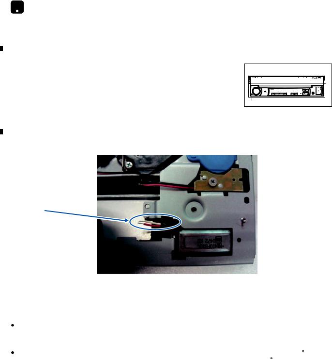
8.Disc Removal Method At No Power
You can add a about 3V-4V DC voltage between "Load+"(Red) with "Load-"(White).
C
|
|
White : Load- |
|
|
Red : Load+ |
|
|
|
|
|
|
D |
|
|
|
|
1.2 NOTES ON SOLDERING |
|
|
|
|
|
|
|
|
For environmental protection, lead-free solder is used on the printed circuit boards mounted in this unit. |
|
|
Be sure to use lead-free solder and a soldering iron that can meet specifications for use with lead-free solders for repairs |
E |
accompanied by reworking of soldering. |
|
|
|
Compared with conventional eutectic solders, lead-free solders have higher melting points, by approximately 40 C. |
|
|
Therefore, for lead-free soldering, the tip temperature of a soldering iron must be set to around 373 C in general, although |
|
|
the temperature depends on the heat capacity of the PC board on which reworking is required and the weight of the tip of |
|
|
the soldering iron. |
|
|
Compared with eutectic solders, lead-free solders have higher bond strengths but slower wetting times and higher melting |
|
|
|
|
|
temperatures (hard to melt/easy to harden). |
The following lead-free solders are available as service parts:
 Parts numbers of lead-free solder:
FGYP1006 1.0 in dia. GYP1007 0.6 in dia. GYP1008 0.3 in dia.
4 |
|
|
|
AVH-3500DVD/XEUC |
|
|
|
|
|||
|
|
1 |
|
2 |
|
|
|
3 |
|
4 |
|
|
|
|
|
|
|
|
|
||||

|
|
5 |
|
|
6 |
|
|
7 |
|
8 |
|
|
|
|
|
||||||
|
2. SPECIFICATIONS |
|
|
|
||||||
|
2.1 SPECIFICATIONS |
|
|
|
|
|
|
|||
|
AVH-3500DVD/XEUC |
|
|
|
|
|
|
|||
|
General |
|
|
|
|
|
|
|
|
|
|
Rated power source .......................................... |
14.4 V DC (allowable voltage range: 10.5 V to 16 V |
|
|
|
|||||
|
|
|
|
|
DC) |
|
|
|
||
|
Preout maximum output level............................ |
2 V |
|
|
|
|||||
|
Maximum current consumption ......................... |
10.0 A |
|
|
|
|||||
|
Backup current |
.................................................. |
|
|
5 mA or less |
|
|
|
||
|
Dimensions (W × H × D): |
|
|
|
|
|
|
|||
|
D |
|
|
|
|
|
|
|
|
|
|
Chassis........ |
178mm x 50mm x 165mm (7in. x 2in. x 6-1/2in.) |
|
|
|
|||||
|
Nose............ |
170mm x 46mm x 27mm (6 -3/4in. x 1-3/4in. x 1in.) |
|
|
|
|||||
|
Weight ............................................................... |
|
|
|
2.0 kg (4.4 lbs) |
|
|
|
||
|
Display |
|
|
|
|
|
|
|
|
|
|
Screen size/aspect ratio .................................... |
7 inch wide/16:9 |
|
|
|
|||||
|
|
|
|
|
(effective display area: 153.6*86.64 mm) |
|
|
|
||
|
Pixels................................................................. |
|
|
|
800*480 |
|
|
|
|
|
|
Durable temperature range (power off) ............. |
–4°F to +140°F |
|
|
|
|||||
A
B
DVD Player
...............................................................System |
DVD video, Video CD, CD,WMA, MP3, DivX, JPEG |
|
|
||
|
system |
|
Usable disc........................................................ |
DVD video, Video CD, CD, CD-R/RW, DVD±R/RW/ |
|
|
R DL |
|
Region number.................................................. |
1 |
|
Frequency response.......................................... |
20 Hz to 20 kHz (with DVD, at sampling frequency |
|
|
96 kHz) |
|
Signal-to-noise ratio........................................... |
75 dB (1 kHz) (IEC-A network) (RCA level) |
C |
Output level: |
|
|
1.0 Vp-p/75 Ω (±0.2 V) |
|
|
Video ........................................................ |
|
|
Number of channels .......................................... |
2 (stereo) |
|
MP3 decoding format ........................................ |
MPEG-1 & 2 Audio Layer 3 |
|
WMA decoding format....................................... |
Ver. 7, 7.1, 8, 9, 10, 11 (2ch audio) (Windows Media |
|
|
Player) |
|
DivX decoding format ........................................ |
Home Theater Ver. 3, 4, 5.2, 6 (.avi, .divx) |
|
DVD video output |
NTSC |
|
|
Audio
Maximum power output ..................................... |
50 W × 4 |
Continuous power output................................... |
22 W × 4 (50 Hz to 15 000 Hz, 10 %THD, 4 Ω load, |
|
both channels driven) |
Load impedance................................................ |
4 Ω (4 Ω to 8 Ω (2 Ω for 1 ch) allowable) |
Preout maximum output level............................ |
2 V |
Equalizer (3-Band Graphic Equalizer): |
|
Frequency ................................................ |
100Hz/1KHz/10KHz |
Gain.......................................................... |
-12dB to +12dB |
Subwoofer (mono): |
|
Frequency ................................................................ |
80 Hz/120 Hz/160 Hz |
Gain ......................................................................... |
-79 dB to 0 dB |
USB
USB standard specification ................................................. |
USB 1.1, USB 2.0 full speed |
Maximum current supply ..................................................... |
500mA |
File system .......................................................................... |
FAT16, FAT32 |
D
E
FM tuner
Frequency range ................................................................. |
87.9 MHz to 107.9 MHz |
Usable sensitivity................................................................. |
15dBuv (S/N: 30 dB) |
AM tuner
Frequency range ................................................................. |
530 kHz to 1710 kHz (10 kHz) |
Usable sensitivity................................................................. |
30 dBuv (S/N: 20 dB) |
Note:
Specifications and the design are subject to modifications without notice.
F
|
|
|
|
AVH-3500DVD/XEUC |
|
|
|
5 |
|
||
|
5 |
|
6 |
|
|
7 |
|
8 |
|
|
|
|
|
|
|
|
|
||||||

|
1 |
|
2 |
|
3 |
|
4 |
|
|
|
|
|
|
A  AVH-3500DVD/XEUW5
|
.........................................Backup current |
5 mA or less |
B
C
D
E
F
6 |
|
|
|
AVH-3500DVD/XEUC |
|
|
|
|
|||
|
|
1 |
|
2 |
|
|
|
3 |
|
4 |
|
|
|
|
|
|
|
|
|
||||

|
5 |
|
6 |
|
7 |
|
|
|
|
|
 AVH-3550DVD/XERC
General
Rated power source .......................................... |
14.4 V DC (allowable voltage range: 10.5 V to 16 V |
|
|
|
DC) |
Preout maximum output level............................ |
2 V |
|
Maximum current consumption ......................... |
10.0 A |
|
Backup current |
.................................................. |
5 mA or less |
Dimensions (W × H × D): |
|
|
D |
|
|
Chassis........ |
178mm x 50mm x 165mm |
|
Nose............ |
170mm x 46mm x 27mm |
|
Weight ............................................................... |
|
2.0 kg |
Display
Screen size/aspect ratio .................................... |
7 inch wide/16:9 |
|
(effective display area: 153.6*86.64 mm) |
Pixels................................................................. |
800*480 |
Durable temperature range (power off) ............. |
–20°C to +60°C |
DVD Player
System............................................................... |
DVD video, Video CD, CD,WMA, MP3, DivX, JPEG |
|
system |
Usable disc........................................................ |
DVD video, Video CD, CD, CD-R/RW, DVD±R/RW/ |
|
R DL |
Region number.................................................. |
3 |
Frequency response.......................................... |
20 Hz to 20 kHz (with DVD, at sampling frequency |
|
96 kHz) |
Signal-to-noise ratio........................................... |
75 dB (1 kHz) (IEC-A network) (RCA level) |
Output level: |
1.0 Vp-p/75 Ω (±0.2 V) |
Video ........................................................ |
|
Number of channels .......................................... |
2 (stereo) |
MP3 decoding format ........................................ |
MPEG-1 & 2 Audio Layer 3 |
WMA decoding format....................................... |
Ver. 7, 7.1, 8, 9, 10, 11 (2ch audio) (Windows Media |
|
Player) |
DivX decoding format ........................................ |
Home Theater Ver. 3, 4, 5.2, 6 (.avi, .divx) |
DVD video output .............................................. |
NTSC |
Audio
Maximum power output ..................................... |
50 W × 4 |
Continuous power output................................... |
22 W × 4 (50 Hz to 15 000 Hz, 10 %THD, 4 Ω load, |
|
both channels driven) |
Load impedance................................................ |
4 Ω (4 Ω to 8 Ω (2 Ω for 1 ch) allowable) |
Preout maximum output level............................ |
2 V |
Equalizer (3-Band Graphic Equalizer): |
|
Frequency ................................................ |
100Hz/1KHz/10KHz |
Gain.......................................................... |
-12dB to +12dB |
Subwoofer (mono): |
|
Frequency................................................................ |
80 Hz/120 Hz/160 Hz |
Gain ......................................................................... |
-79 dB to 0 dB |
USB
USB standard specification ................................................. |
USB 1.1, USB 2.0 full speed |
Maximum current supply ..................................................... |
500mA |
File system .......................................................................... |
FAT16, FAT32 |
FM tuner
Frequency range ................................................................. |
87.5 MHz to 108.0 MHz |
Usable sensitivity................................................................. |
15dBuv (S/N: 30 dB) |
AM tuner
Frequency range ................................................................. |
531 kHz to 1 602 kHz (9 kHz) |
|
530 kHz to 1 640 kHz (10 kHz) |
Usable sensitivity................................................................. |
30 dBuv (S/N: 20 dB) |
Note:
Specifications and the design are subject to modifications without notice.
AVH-3500DVD/XEUC
|
5 |
|
6 |
|
|
|
7 |
|
|
|
|
|
|
|
|||
|
|
|
|
|
|
8
A
B
C
D
E
F
8 7

|
1 |
|
2 |
|
3 |
|
4 |
|
|
|
|
|
|
A  AVH-3550DVD/XERD
General
|
Rated power source .......................................... |
14.4 V DC (allowable voltage range: 10.5 V to 16 V |
|
|
|
|
DC) |
|
Preout maximum output level............................ |
2 V |
|
|
Maximum current consumption ......................... |
10.0 A |
|
|
Backup current |
.................................................. |
5 mA or less |
|
Dimensions (W × H × D): |
|
|
|
|
||
|
D |
|
|
|
Chassis........ |
178mm x 50mm x 165mm |
|
|
Nose............ |
170mm x 46mm x 27mm |
|
|
Weight ............................................................... |
|
2.0 kg |
B |
Display |
|
|
Screen size/aspect ratio |
7 inch wide/16:9 |
||
|
|||
|
|
(effective display area: 153.6*86.64 mm) |
|
|
Pixels................................................................. |
800*480 |
|
|
Durable temperature range (power off) ............. |
–20°C to +60°C |
DVD Player
|
|
...............................................................System |
DVD video, Video CD, CD,WMA, MP3, DivX, JPEG |
|
|
||
|
|
|
system |
|
|
Usable disc........................................................ |
DVD video, Video CD, CD, CD-R/RW, DVD±R/RW/ |
|
|
|
R DL |
|
|
Region number.................................................. |
4 |
|
|
Frequency response.......................................... |
20 Hz to 20 kHz (with DVD, at sampling frequency |
|
|
|
96 kHz) |
C |
Signal-to-noise ratio........................................... |
75 dB (1 kHz) (IEC-A network) (RCA level) |
|
Output level: |
|
||
|
|
1.0 Vp-p/75 Ω (±0.2 V) |
|
|
|
Video ........................................................ |
|
|
|
Number of channels .......................................... |
2 (stereo) |
|
|
MP3 decoding format ........................................ |
MPEG-1 & 2 Audio Layer 3 |
|
|
WMA decoding format....................................... |
Ver. 7, 7.1, 8, 9, 10, 11 (2ch audio) (Windows Media |
|
|
|
Player) |
|
|
DivX decoding format ........................................ |
Home Theater Ver. 3, 4, 5.2, 6 (.avi, .divx) |
|
|
..............................................DVD video output |
NTSC |
Audio
|
|
Maximum power output ..................................... |
50 W × 4 |
|
|
|
Continuous power output................................... |
22 W × 4 (50 Hz to 15 000 Hz, 10 %THD, 4 Ω load, |
|
|
|
|
both channels driven) |
|
D |
Load impedance................................................ |
4 Ω (4 Ω to 8 Ω (2 Ω for 1 ch) allowable) |
||
Preout maximum output level |
2 V |
|||
|
|
|||
|
|
Equalizer (3-Band Graphic Equalizer): |
|
|
|
|
Frequency ................................................ |
100Hz/1KHz/10KHz |
|
|
|
Gain.......................................................... |
-12dB to +12dB |
|
|
|
Subwoofer (mono): |
|
|
|
|
................................................................Frequency |
80 Hz/120 Hz/160 Hz |
|
|
|
|||
|
|
Gain ......................................................................... |
-79 dB to 0 dB |
|
USB
|
USB standard specification ................................................. |
USB 1.1, USB 2.0 full speed |
|
Maximum current supply ..................................................... |
500mA |
E |
File system .......................................................................... |
FAT16, FAT32 |
FM tuner
Frequency range ................................................................. |
87.5 MHz to 108.0 MHz |
Usable sensitivity................................................................. |
15dBuv (S/N: 30 dB) |
AM tuner
|
Frequency range ................................................................. |
531 kHz to 1 602 kHz (9 kHz) |
|
|
530 kHz to 1 640 kHz (10 kHz) |
|
Usable sensitivity................................................................. |
30 dBuv (S/N: 20 dB) |
F |
Note: |
|
Specifications and the design are subject to modifications without notice. |
||
8 |
|
|
|
AVH-3500DVD/XEUC |
|
|
|
|
|||
|
|
1 |
|
2 |
|
|
|
3 |
|
4 |
|
|
|
|
|
|
|
|
|
||||

|
5 |
|
6 |
|
7 |
|
|
|
|
|
 AVH-3550DVD/XERI
General
Rated power source .......................................... |
14.4 V DC (allowable voltage range: 10.5 V to 16 V |
|
|
|
DC) |
Preout maximum output level............................ |
2 V |
|
Maximum current consumption ......................... |
10.0 A |
|
Backup current |
.................................................. |
5 mA or less |
Dimensions (W × H × D): |
|
|
DIN |
|
|
Chassis........ |
180mm x 50mm x 160mm |
|
Nose............ |
188mm x 58mm x 32mm |
|
D |
|
|
Chassis........ |
178mm x 50mm x 165mm |
|
Nose............ |
170mm x 46mm x 27mm |
|
Weight ............................................................... |
|
2.0 kg |
Display
Screen size/aspect ratio .................................... |
7 inch wide/16:9 |
|
(effective display area: 153.6*86.64 mm) |
Pixels................................................................. |
800*480 |
Durable temperature range (power off) ............. |
–20°C to +60°C |
DVD Player
System............................................................... |
DVD video, Video CD, CD,WMA, MP3, DivX, JPEG |
|
system |
Usable disc........................................................ |
DVD video, Video CD, CD, CD-R/RW, DVD±R/RW/ |
|
R DL |
Region number.................................................. |
2 |
Frequency response.......................................... |
20 Hz to 20 kHz (with DVD, at sampling frequency |
|
96 kHz) |
Signal-to-noise ratio........................................... |
75 dB (1 kHz) (IEC-A network) (RCA level) |
Output level: |
1.0 Vp-p/75 Ω (±0.2 V) |
Video ........................................................ |
|
Number of channels .......................................... |
2 (stereo) |
MP3 decoding format ........................................ |
MPEG-1 & 2 Audio Layer 3 |
WMA decoding format....................................... |
Ver. 7, 7.1, 8, 9, 10, 11 (2ch audio) (Windows Media |
|
Player) |
DivX decoding format ........................................ |
Home Theater Ver. 3, 4, 5.2, 6 (.avi, .divx) |
DVD video output .............................................. |
NTSC |
Audio
Maximum power output ..................................... |
50 W × 4 |
Continuous power output................................... |
22 W × 4 (50 Hz to 15 000 Hz, 10 %THD, 4 Ω load, |
|
both channels driven) |
Load impedance................................................ |
4 Ω (4 Ω to 8 Ω (2 Ω for 1 ch) allowable) |
Preout maximum output level............................ |
2 V |
Equalizer (3-Band Graphic Equalizer): |
|
Frequency ................................................ |
100Hz/1KHz/10KHz |
Gain.......................................................... |
-12dB to +12dB |
Subwoofer (mono): |
|
Frequency................................................................ |
80 Hz/120 Hz/160 Hz |
Gain ......................................................................... |
-79 dB to 0 dB |
USB
USB standard specification ................................................. |
USB 1.1, USB 2.0 full speed |
Maximum current supply ..................................................... |
500mA |
File system .......................................................................... |
FAT16, FAT32 |
FM tuner
Frequency range ................................................................. |
87.5 MHz to 108.0 MHz |
Usable sensitivity................................................................. |
15dBuv (S/N: 30 dB) |
AM tuner
Frequency range ................................................................. |
531 kHz to 1 602 kHz (9 kHz) |
|
530 kHz to 1 640 kHz (10 kHz) |
Usable sensitivity................................................................. |
30 dBuv (S/N: 20 dB) |
Note:
Specifications and the design are subject to modifications without notice.
AVH-3500DVD/XEUC
|
5 |
|
6 |
|
|
|
7 |
|
|
|
|
|
|
|
|||
|
|
|
|
|
|
8
A
B
C
D
E
F
8 9

|
1 |
|
2 |
|
3 |
|
4 |
|
|
|
|
|
|
2.2 DISC/CONTENT FORMAT
A
 is a trademark of DVD Format/Logo Licensing Corporation.
B
C
D
E
F
10 |
|
|
|
AVH-3500DVD/XEUC |
|
|
|
|
|||
|
|
1 |
|
2 |
|
|
|
3 |
|
4 |
|
|
|
|
|
|
|
|
|
||||
|
5 |
|
6 |
|
7 |
|
8 |
|
|
|
|
3. BASIC ITEMS FOR SERVICE
3.1 CHECK POINTS AFTER SERVICING
To keep the product quality after servicing, please confirm following check points.
No. |
|
Procedures |
Item to be confirmed |
1 |
|
Confirm whether the customer complain has |
The customer complain must not be |
|
|
been solved. |
reappeared. |
|
|
If the customer complain occurs with the |
Display, video, audio and operations must be |
|
|
specific media, use it for the operation check. |
normal. |
|
|
|
|
2 |
Flap-mecha |
Check the operation of the flap mechanism. |
The flap mechanism operation must be |
|
|
|
smooth without making the noise and |
|
|
|
scratches. |
|
|
|
|
3 |
DVD |
Play back a DVD. |
Display, video, audio and operations must be |
|
|
(Menu operation; Title/chapter search) |
normal. |
|
|
|
|
4 |
CD |
Play back a CD. |
Display, audio and operations must be |
|
|
(Track search) |
normal. |
|
|
|
|
5 |
FM/AM tuner |
Check FM/AM tuner action. |
Display, audio and operations must be |
|
|
(Seek, Preset) |
normal. |
|
|
Switch band to check both FM and AM. |
|
|
|
|
|
6 |
|
Check whether no disc is inside the product. |
The media used for the operating check must |
|
|
|
be ejected. |
|
|
|
|
7 |
|
Appearance check |
No scratches or dirt on its appearance after |
|
|
|
receiving it for service. |
|
|
|
|
For check items concerning image and voice, please refer to the followings:
Check items concerning image |
Check items concerning voice |
|
|
Block-noise |
Distortion |
Crosscut noise |
Noise |
Dot noise |
Low volume |
Distorted image (Image skip) |
High volume |
Low brightness |
Changes in level |
Too bright |
Pause of sound |
Color fading |
|
Partial discoloration |
|
|
|
|
|
AVH-3500DVD/XEUC |
|
|
|
11 |
||
|
5 |
|
6 |
|
|
7 |
|
8 |
|
|
|
|
|
|
|
||||||
A
B
C
D
E
F

|
1 |
|
2 |
|
3 |
|
4 |
|
|
|
|
|
|
3.2 PCB LOCATIONS
A
D TFT SMT Unit 
B KB PCB |
B
C AUX PCB
E
F
 A
A
Main PCB Unit
SW PCB Unit
MB PCB Assy
C
D
E
F
12
A:AVH-3500DVD/XEUC
B:AVH-3500DVD/XEUW5
C:AVH-3550DVD/XERC
D:AVH-3550DVD/XERD
E:AVH-3550DVD/XERI
Unit Number |
: 843DV7791GNMB004(A) |
Unit Number |
: 843DV7791GRMB004(B) |
Unit Number |
: 843DV7791GAMB004(C) |
Unit Number |
: 843DV7791GLMB004(D) |
Unit Number |
: 843DV7791GMMB004(E) |
Unit Name |
: MB PCB Assy |
Keyboard Assy |
|
Consists of |
|
KB PCB |
|
AUX PCB |
|
Unit Number |
: 843DV7791GAKB004 |
Unit Name |
: Keyboard Assy |
Unit Number |
: |
Unit Name |
: TFT SMT Unit |
Unit Number |
: EWX2008 |
Unit Name |
: Main PCB Unit |
Unit Number |
: EWX2009 |
Unit Name |
: SW PCB Unit |
AVH-3500DVD/XEUC
1 |
|
2 |
|
|
|
3 |
|
4 |
|
|
|
|
|
|
|

|
5 |
|
6 |
|
|
3.3 JIGS LIST
Display Module Unit
GGF1461
GGD1170

TFT PCB Assy
- Jigs List
|
7 |
|
8 |
|
|
|
|
A
Mother PCB Assy
B
C
GGD1250
DVD Mechanism Module
Name |
Jig No. |
Remarks |
D |
|
50P FFC |
GGD1250 |
DVD Mecha - Main PCB |
|
|
40P FFC |
GGD1170 |
Monitor PCB |
|
|
40P + 20P Extension Board |
GGF1461 |
Monitor PCB |
|
|
|
|
|
|
|
|
|
|
|
|
E
3.4 CLEANING
Before shipping out the product, be sure to clean the following portions by using the prescribed cleaning tools:
|
|
Portions to be cleaned |
Cleaning tools |
|
|
|
|
|
|
|||||
|
|
DVD pickup lenses |
Cleaning liquid : GEM1004 |
|
|
|
|
|
|
|
|
|||
|
|
|
Cleaning paper : GED-008 |
|
|
|
|
|
|
|||||
|
|
|
|
|
|
|
|
|
|
|
|
|
|
F |
|
|
|
|
|
|
|
|
|
|
|
|
|
|
|
|
|
Portions to be cleaned |
Cleaning tools |
|
|
|
|
|
|
|||||
|
|
Fans |
Cleaning paper : GED-008 |
|
|
|
|
|
|
|
|
|||
|
|
|
|
|
|
|
|
|
|
|
|
|
|
|
|
|
|
|
|
|
|
|
|
|
|
|
|
|
|
|
|
|
|
|
|
AVH-3500DVD/XEUC |
|
|
|
13 |
|
|||
|
5 |
|
|
6 |
|
|
|
|
7 |
|
8 |
|
|
|
|
|
|
|
|
|
|
|
|
||||||
|
1 |
|
2 |
|
3 |
|
4 |
|
|
|
|
|
|
4. BLOCK DIAGRAM
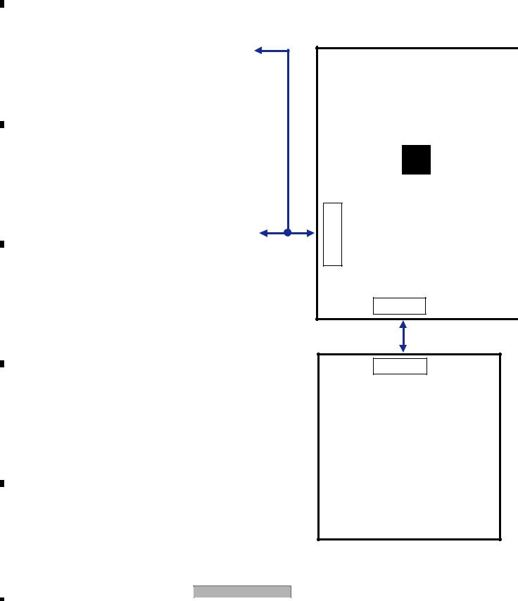
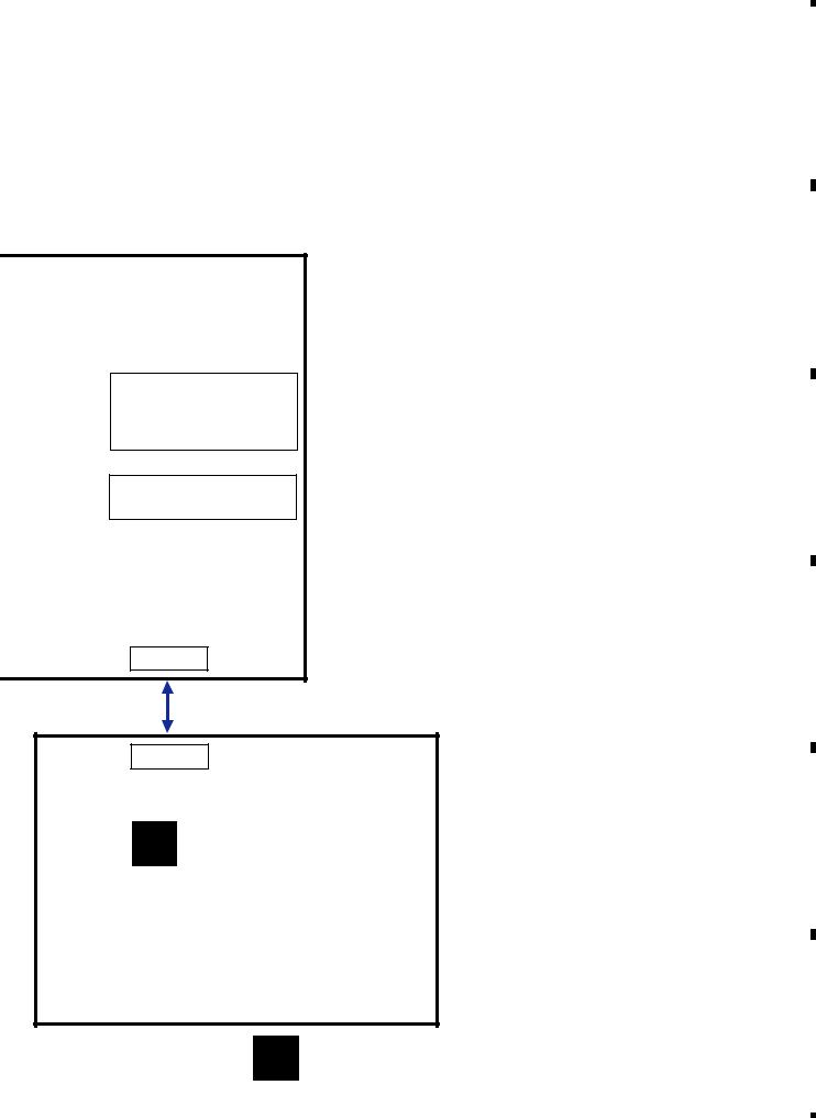
4.1 OVERALL CONNECTION DIAGRAM
A
B
C
D
E
F
14
|
|
|
|
|
|
|
|
|
|
|
|
|
|
|
|
|
|
E |
|
|
F |
|
|
|
|
|
|
||
|
|
|
to |
|
|
|||||||||
|
|
|
|
|
|
|
|
|
|
|
|
|
||
|
|
DRIVE UNIT |
|
BDMain |
|
|||||||||
|
|
|
|
|
|
|
||||||||
|
|
|
|
|
|
|
|
|
|
|
|
|
|
|
|
|
|
|
|
|
|
|
|
|
|
|
|
|
|
|
|
|
|
|
|
|
|
|
|
|
|
|
|
|
|
|
|
|
|
|
|
|
|
|
|
|
|
||
|
|
|
|
D |
|
|
|
|
|
|
|
|||
|
|
|
|
CON801 |
|
|||||||||
|
|
TFT SMT UNIT |
|
|||||||||||
|
|
|
|
|
|
|
|
|
|
|
|
|
|
|
|
|
|
|
|
|
|
|
|
|
|
|
|
|
|
|
|
CON802 : |
|
|
|
CON803 : |
|
|
|
|
||||
|
|
to TFT-LCD |
|
|
|
to Touch Panel |
|
|
||||||
|
|
|
|
|
|
|
|
|
|
|
|
|
|
|
|
|
|
|
|
|
|
|
|
|
|
|
|
|
|
CON102 : |
|
J114 : |
Power Connector |
|
EXT DTV/AT |
|
|
|
A MB PCB A
J110
J111
CON505
DVD MECHANISM
MODULE
CON501 : |
|
CON504 : |
to Pick-up |
|
to Spindle Motor |
|
|
|
AVH-3500DVD/XEUC
1 |
|
2 |
|
|
|
3 |
|
4 |
|
|
|
|
|
|
|
|
5 |
|
6 |
|
7 |
|
8 |
|
|
|
|
|
|
CON101 : |
ATV Connector |
|
FAN Connector |
|
|
|
J108 :
4.1CH Line OUT,
ASSY Vedio out and Camera in
J109 :
Rear AV-IN and SWC
J112
CON601
B KB PCB
CON603 : |
|
CON602: |
Front USB Connector |
|
Front AV-IN Connector |
|
|
|
C AUX PCB
|
|
|
|
AVH-3500DVD/XEUC |
|
|
|
15 |
||
|
5 |
|
6 |
|
|
7 |
|
8 |
|
|
|
|
|
|
|
||||||
A
B
C
D
E
F

|
1 |
|
2 |
|
3 |
|
4 |
|
|
|
|
|
|
4.2 BLOCK DIAGRAM
A
|
|
|
|
FM/AM Tuner |
|
|
IIC |
|
||||||
|
|
|
|
|
NXP6626 |
|
|
|
|
|
|
IIC |
||
|
|
|
|
|
|
|
|
|
||||||
|
|
|
|
|
|
|
|
|
|
|
|
|||
|
|
|
|
|
|
|
|
|
|
|
|
MCU |
||
|
|
|
|
|
|
|
|
|
|
|
|
|||
|
|
|
|
|
|
MPX |
|
|
|
|
||||
|
|
|
|
|
|
|
|
|
|
|
|
|
|
|
|
|
|
|
RDS Decoder |
|
|
|
|
|
|
|
|||
|
|
|
|
|
|
RDS_IIC |
|
|
|
|
||||
|
|
|
|
U123 |
|
|
|
|
U128 |
|||||
|
|
|
|
|
|
|
|
|||||||
|
|
|
|
PT2579 |
(NC) |
|
|
|
STM8S207M8T6B |
|||||
UART
EXT DTV/ATV
B
I/O POART
EXT I/O&DET
A MB PCB ASSY
|
|
|
|
|
|
|
|
|
|
|
|
|
|
|
|
|
|
|
|
CON101 |
|
|
|
|
|
|
|
|
|
|
|
|
|
|
|
|
|
|
|
|
|
|
|
|
|
|
|
|
|
|
|
|
|
|
|
|
|
|
|
|
|
|
|
|
|
|
|
|
|
|
|
|
|
|
|
|
|
|
|
C |
|
|
|
|
|
|
|
|
|
FAN |
|
|
|
|
|
|
|
|
|
|
|
|
|
|
|
|
|
|
|
||||||||||
|
|
|
|
|
|
|
|
|
|
|
|
|
|
|
|
|
|
|
|
|
|
|
|
|
|
|
|
|
|||||||||||
|
|
|
|
|
|
|
|
|
|
|
|
|
|
|
|
|
|
|
|
|
|
|
|
|
|
|
|
|
|
||||||||||
|
|
|
|
|
|
|
|
|
|
|
|
|
|
|
|
|
|
|
|
|
|
|
|
|
|
|
|
|
|
||||||||||
|
|
|
|
|
|
|
|
|
|
|
|
|
|
|
|
|
|
|
|
|
|
|
|
|
|
|
|
|
|
||||||||||
|
|
|
|
|
|
|
|
|
|
|
|
|
|
|
|
|
|
|
|
|
|
|
|
|
|
|
|
|
|
|
|
|
|
|
|
|
|
|
|
|
|
|
|
|
|
|
|
|
|
|
|
|
|
|
|
|
|
|
|
|
|
|
EXT SWC |
|
|
KEY AD |
|
|
|
|
|
|
|
|
|
||||
|
|
|
|
|
|
|
|
|
|
|
|
|
|
|
|
|
|
|
|
|
|
|
|
|
|
|
|
|
|
|
|
|
|
|
|
||||
|
|
|
|
|
|
|
|
|
|
E |
|
F |
J110 |
|
|
|
|
|
|
|
|
|
|
|
|
|
|
|
|
|
|
|
|||||||
|
|
|
|
|
|
|
|
|
|
|
|
|
|
|
|
|
|
|
|
|
|
|
|
|
|
|
|
|
|||||||||||
|
|
|
|
|
|
|
|
|
|
|
|
|
|
|
|
|
|
|
|
|
|
|
|
|
|
|
|
|
|||||||||||
|
|
|
|
|
|
|
|
|
|
|
|
|
|
|
|
|
|
|
|
|
|
|
|
|
|
|
|
|
|
|
|
|
|
|
|
|
|
|
|
|
|
|
|
|
|
|
|
|
|
DRIVE UNIT |
|
|
|
|
|
|
|
|
|
|
|
|
|
|
|
|
|
|
|
|
|||||||||
|
|
|
|
|
|
|
|
|
|
|
|
|
|
|
|
|
|
|
|
|
|
|
|
|
|
|
|
|
|
||||||||||
|
|
|
|
|
|
|
|
|
|
|
|
|
|
|
|
|
|
|
|
|
|
|
|
|
|
|
|
|
|
|
AUX1 Video(CVBS) |
|
|||||||
|
|
|
|
|
|
|
|
|
|
|
|
|
|
|
|
|
|
|
|
|
|
|
|
|
|
|
|
|
|
|
|
||||||||
|
|
|
|
|
|
|
|
|
|
|
|
|
|
|
|
|
|
|
|
|
|
|
|
|
|
|
|
|
|
|
|
|
|
|
|||||
D |
|
|
|
|
|
|
|
|
|
|
|
|
|
|
|
|
|
|
|
|
|
AUX2 Video(CVBS) |
|
||||||||||||||||
|
|
|
|
|
|
|
|
|
|
|
|
|
|
|
|
|
|
|
|
|
|
||||||||||||||||||
|
|
|
|
|
|
|
|
|
|
|
|
|
|
|
|
|
|
|
|
|
|
|
|
|
|
|
|
|
|
||||||||||
|
|
|
|
|
|
|
|
|
|
|
|
|
|
|
|
|
|
|
|
|
|
|
|
|
|
|
|
|
|
|
DVD Video(CVBS) |
|
|||||||
|
|
|
|
|
|
|
|
|
|
|
|
|
|
|
|
|
|
|
|
|
|
|
|
|
|
|
|
|
|
|
|
||||||||
|
|
|
|
|
|
|
|
|
|
|
|
|
|
|
|
|
|
|
|
|
|
|
|
|
|
|
|
|
|
|
|
|
|
|
|||||
|
|
|
|
|
|
|
|
|
|
|
|
|
|
|
|
|
|
|
|
|
|
|
|
|
|
|
|
|
|
|
Camera Video(CVBS) |
|
|||||||
|
|
|
|
|
|
|
|
|
|
|
|
|
|
|
|
|
|
|
|
|
|
|
|
|
|
|
|
|
|
|
|
||||||||
|
|
|
|
|
|
|
|
|
|
|
|
|
|
|
|
|
|
|
|
|
|
|
|
|
|
|
|
|
|
|
|
|
|
|
|||||
|
|
|
|
|
|
|
|
|
|
|
|
|
|
|
|
|
|
|
|
|
|
|
|
|
|
|
|
|
|
|
|
|
|||||||
|
|
|
|
|
|
|
|
|
|
|
|
|
|
|
|
|
|
|
|
|
|
|
|
|
|
|
|
|
|
|
DTV/ATV Video(CVBS) |
|
|||||||
|
|
|
|
|
|
|
|
|
|
|
|
|
|
|
|
|
|
|
|
|
|
|
|
|
|
|
|
|
|
|
|
||||||||
|
|
|
|
|
|
|
|
|
|
|
|
|
|
|
|
|
|
|
|
|
|
|
|
|
|
|
|
|
|
|
|
|
|
|
|
|
|
|
|
|
|
|
|
|
|
|
|
|
|
|
|
|
|
|
|
|
|
|
|
|
|
|
|
|
|
|
|
|
|
|
|
|
|
|
|
|
|
|
|
|
|
|
|
|
|
|
|
|
|
|
|
|
|
|
|
|
|
|
|
|
|
|
|
|
|
|
|
|
|
|
|
|
|
|
|
|
|||
|
|
|
|
|
|
|
|
|
|
|
|
|
|
|
|
|
|
|
|
|
|
|
|
|
|
|
|
|
|
|
|
|
|
|
|
|
|
|
|
|
|
|
|
|
|
|
CON603 |
CON601 |
|
|
|
|
|
J112 |
|
|
USB Detector |
|
|
|
|
|
|
|
|
|
|
|
|
||||||||||
|
|
|
Front USB |
|
|
|
|
|
|
|
|
U116 |
|
|
|
|
|
|
|
|
|
|
|
|
|||||||||||||||
|
|
|
|
|
|
|
|
|
|
|
|
|
|
|
|
|
|
|
|
|
|
|
|
|
|
|
|
|
|
|
|
||||||||
E |
|
|
|
|
|
|
|
|
|
|
|
|
|
AD8092 |
|
|
|
|
|
|
|
|
|
|
|
|
|||||||||||||
|
|
|
|
|
|
|
|
|
|
|
|
|
|
|
|
|
|
|
|
|
|
|
|
|
|
|
|
|
|
||||||||||
|
|
|
|
|
|
|
|
|
|
|
|
|
|
|
|
|
|
|
|
|
|
|
|
|
|
|
|
|
|
||||||||||
|
|
|
|
|
|
|
|
|
|
|
|
|
|
|
|
|
|
|
|
|
|
|
|
|
Audio |
|
|||||||||||||
|
|
|
|
|
|
|
|
|
|
|
|
|
|
|
|
|
|
|
|
|
|
|
FM/AM Audio L/R |
|
|
|
|
|
|
||||||||||
|
|
|
|
C |
|
|
|
|
|
|
|
|
|
|
|
|
|
|
|
|
|
|
|
|
|
|
|
|
|
|
|
|
|
|
Processor |
|
|||
|
|
|
|
|
|
|
|
|
|
|
|
|
|
|
|
|
|
DVD Audio L/R |
|
|
|
|
|
|
|
|
|
|
|
|
|||||||||
|
|
|
|
|
|
|
|
|
|
|
|
|
|
|
|
|
|
|
|
|
|
|
|
|
|
|
|||||||||||||
|
|
AUX PCB |
|
|
|
|
|
|
|
|
|
|
|
|
|
|
|
|
|
|
|
|
|
|
|
|
|
|
U124 |
|
|||||||||
|
|
|
|
|
|
|
|
|
|
|
|
|
|
|
SW |
|
|
|
|
|
|
|
|
|
|||||||||||||||
|
|
|
|
|
|
|
|
|
|
|
|
|
|
|
|
|
|
|
|
|
|
|
|
|
|
|
|
|
|
|
|
|
|||||||
|
|
AUX1 Audio L/R |
|
|
|
|
|
|
|
|
|
|
|
|
|
|
|
|
|
|
|
|
|
|
|
|
|
TDA7419 |
|
||||||||||
|
|
CON602 |
CON601 |
|
|
|
|
|
J112 |
|
|
|
|
|
|
|
|
|
|
||||||||||||||||||||
|
|
|
|
|
|
|
|
|
|
|
|
|
|
|
|
|
|
|
|
|
|
|
|
|
|
|
|
|
|
|
|||||||||
|
|
AUX2 Audio L/R |
|
|
|
|
|
|
|
|
|
|
|
|
|
|
|
|
|
U113 / U114 |
|
|
|
|
|
|
|
|
|
|
|
|
|||||||
|
|
|
|
|
|
|
|
|
|
|
|
|
|
|
|
|
|
|
|
|
|
|
|
|
|
|
|
|
|
|
|
|
|
|
|||||
|
|
|
|
|
|
|
|
|
|
|
|
|
|
|
|
|
|
|
|
|
|
|
|
|
|
|
|
|
|
|
|
|
|
|
|||||
|
|
|
|
|
|
|
|
|
|
|
|
|
|
|
|
|
|
|
|
|
|
|
74HCT4052 |
|
|
|
|
|
|
|
|
|
|
|
|
||||
|
|
|
|
|
|
|
|
B |
KB PCB |
|
|
|
|
|
J114 |
|
|
|
|
|
|
|
|
|
|
|
|
|
|
||||||||||
|
|
|
|
|
|
|
|
|
|
|
|
|
|
|
|
|
|
|
|
|
|
|
|
|
|
|
|
|
|
|
|
||||||||
F |
|
|
DTV/ATV Audio L/R |
|
|
|
|
|
|
|
|
|
|
|
|
|
|
|
|
|
|
|
|
||||||||||||||||
|
|
|
|
|
|
|
|
|
|
|
|
|
|
|
|
|
|
|
|
|
|
|
|||||||||||||||||
|
|
|
|
|
|
|
|
|
|
|
|
|
|
|
|
|
|
|
|
|
|
|
|
|
|
|
|
|
|
|
|
|
|
|
|
|
|
|
|
|
|
|
|
|
|
|
|
|
|
|
|
|
|
|
|
|
|
|
|
|
|
|
|
|
|
|
|
|
|
|
|
|
|
|
|
|
|
|
|
16 |
|
|
|
AVH-3500DVD/XEUC |
|
|
|
|
|||
|
|
1 |
|
2 |
|
|
|
3 |
|
4 |
|
|
|
|
|
|
|
|
|
||||
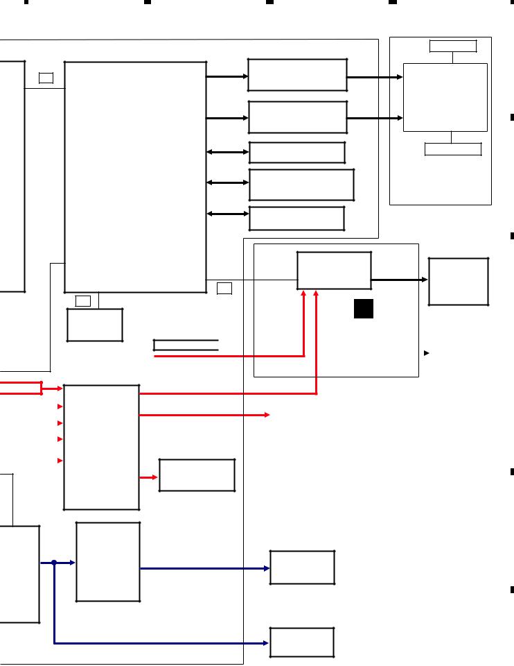
5
IIC
MPEG
U125
ZR36966H
IIS
Audio DAC
U105
CS4344
VBS)
VBS) |
|
|
|
Vedio SW |
|
||||
|
|
|
|
|
VBS) |
|
|
|
U112 |
|
|
|
||
|
|
|
|
|
(CVBS) |
|
|||
|
|
|
FMS6502 |
|
|
|
|
|
|
|
|
|
|
|
eo(CVBS) |
|
|
|
|
|
|
|
|
|
|
|
|
|
|
6 |
|
7 |
|
|
8 |
|
|
|
|
|
Pickup Unit |
|
|
|
|
|
A |
|
Axis motor driver IC |
|
|
CON501 |
|
|
U110 |
|
|
||
|
|
CON505 |
|
||
|
D6849 |
J111 |
|
||
|
Motor driver IC |
SB BD |
|||
|
|
|
|
|
|
|
U111 |
|
|
CON504 |
|
|
BA5954FP |
|
|
||
|
SDRAM |
U122 |
|
|
Spindle Motor |
|
|
M12L64164A |
|
|
|
|
Flash |
U127 |
|
|
B |
|
|
|
DVD Mechanism |
||
|
MX29LV160DB/MX29LV320E |
|
|||
|
|
module |
|||
|
|
|
|
||
|
EEPROM |
U119 |
|
|
|
|
|
S24C16 |
|
|
|
|
|
TFT IC |
|
|
|
J110 |
CON801 |
U804 |
|
CON802 |
TFT LCD |
TW8832 |
|
||||
IIC |
|
|
|
HSD070IDW1 |
|
|
|
|
|
||
|
|
|
|
|
C |
D
DVD-YUV |
|
|
|
TFT SMT UNIT |
|
|
|
|
||||
|
|
|
|
|
|
|
||||||
|
|
|
|
|
CON803 |
Touch |
|
|
|
|||
|
|
|
|
U806 |
|
|
|
|||||
|
|
|
|
|
|
TSC2046 |
|
|
Panel |
|
|
|
|
|
|
|
|
||||||||
|
|
|
|
|
|
|
|
|
|
|
|
|
|
|
|
|
|
|
|
|
|
|
|
|
|
|
CVBS |
|
|
|
|
|
|
|
|
|
|
|
|
|
|
J108 |
|
|
|
|
|
|
D |
||
|
|
Video out |
|
|
|
|
|
|||||
|
|
|
|
|
|
|
|
|
||||
|
|
|
|
|
|
|
|
|
|
|
|
|
Video Detect
U117
BA7071
udio |
Power AMP |
|
E |
|
|
||
cessor |
|
|
|
|
U121 |
CON102 |
Speaker (4ch) |
|
PAL007E |
|
|
|
|
|
|
U124 |
|
|
|
DA7419 |
|
|
|
|
|
J108 |
Lineout (4.1ch) |
|
|
|
|
|
|
|
F |
|
|
|
|
AVH-3500DVD/XEUC |
|
|
|
17 |
|
||
|
5 |
|
6 |
|
|
7 |
|
8 |
|
|
|
|
|
|
|
|
|
||||||

|
|
1 |
|
2 |
|
3 |
|
4 |
|
|
|
|
|
|
|||||
|
|
5. DIAGNOSIS |
|
|
|
|
|
|
|
|
|
5.1 OPERATIONAL FLOWCHART |
|
|
|
|
|
||
A |
Power ON |
|
|
|
|
|
|||
|
Battery = 12V |
|
||
|
|
B5V = 5V |
|
|
B |
|
if ACC on |
|
|
|
|
|
||
|
Acc = 12V |
|
||
|
|
AUTO POWER ON |
|
|
|
|
MAKE POWER_CTL=1 |
|
|
Radio Source |
T5V Power = 5V |
V5V Power = 5V |
||
|
|
|
||
C |
|
|
|
|
Tuner 9v= 9V |
TFT Power On |
Mechanism |
||
and |
TFT initialize |
|||
(Ture_ctl = 1) |
Ready |
|||
|
|
|||
Tuner initialize |
|
Starts |
Wait open key |
|
|
communication |
CMD |
||
|
with mpeg |
|
||
D |
|
|
|
|
|
Source keys |
|
||
|
|
operative |
|
|
Source ON
E
Entery select mode operative
Completes power-on operation.
(After that, proceed to each source operation)
F
18 |
|
|
|
AVH-3500DVD/XEUC |
|
|
|
|
|||
|
|
1 |
|
2 |
|
|
|
3 |
|
4 |
|
|
|
|
|
|
|
|
|
||||

|
5 |
|
|
|
6 |
|
|
7 |
|
|
|
|
|
|
|
|
|||||||||
|
5.2 ERROR CODE LIST |
|
|
|
|
|
|
|||||
|
|
|
|
|
|
|
||||||
|
|
Message |
Cause |
Action |
|
|||||||
|
|
|
|
|
|
|
|
|
|
|
||
|
|
|
|
|
|
|
Please wait, it may take several |
|
|
|
||
|
|
Format Reading |
Disc is being read. |
minutes for some disc or storage |
|
|
|
|||||
|
|
|
|
|
|
|
device. |
|
|
|
||
|
|
|
|
Disc is dirty. |
Clean disc with soft cloth. |
|
|
|
||||
|
|
No Disc |
Disc is upside down. |
Insert disc with label side up. |
|
|
|
|||||
|
|
Disc is not present in loading |
Insert disc. |
|
|
|
||||||
|
|
|
|
|
|
|
||||||
|
|
|
|
compartment. |
|
|
|
|||||
|
|
|
|
|
|
|
|
|
|
|||
|
|
|
|
|
|
|
|
|
||||
|
|
Bad Disc |
|
Disc is dirty. |
Clean disc with soft cloth. |
|
|
|
||||
|
|
|
|
|
|
|
|
|
|
|
|
|
|
|
|
Disc is upside down. |
Insert disc with label side up. |
|
|
|
|||||
|
|
|
|
|
|
|||||||
|
|
|
|
|
|
|
|
|
|
|
||
|
|
Unknown disc |
Disc format is not compatible |
Change another disc. |
|
|
|
|||||
|
|
with this unit. |
|
|
||||||||
|
|
|
|
|
|
|
|
|
|
|||
|
|
Region Error |
DVD is not compatible with |
Use discs with corresponding |
|
|
||||||
|
|
region code of unit. |
regional code. |
|
|
|
||||||
|
|
|
|
|
|
|||||||
|
|
Error |
Illegal mechanism operation. |
Press EJECT key for 5 seconds to |
|
|
||||||
|
|
reset loading mechanism. |
|
|
|
|||||||
|
|
|
|
|
|
|
|
|
||||
|
|
|
|
|
|
|
Check the speaker connection. If the |
|
|
|||
|
|
|
|
Unit fails to operate or speaker |
message fails to disappear even after |
|
|
|||||
|
|
AMP Error |
connection is incorrect; |
the engine is switched off/on, contact |
|
|
||||||
|
|
|
|
protective circuit is activated. |
your dealer or an authorized Pioneer |
|
|
|||||
|
|
|
|
|
|
|
Service Station for assistance. |
|
|
|||
AVH-3500DVD/XEUC
|
5 |
|
6 |
|
|
|
7 |
|
|
|
|
|
|
|
|||
|
|
|
|
|
|
8
A
B
C
D
E
F
8 19

|
1 |
|
2 |
|
3 |
|
4 |
|
|
|
|
|
|
5.3 CONNECTOR FUNCTION DESCRIPTION
A
B
C
ANTENNA BLACK
D
E
WHITE |
OUTPUTFRONTRED |
WHITE |
OUTPUTREARRED |
YELLOW |
BLUE |
UBWOOFERS OUTPUT YELLOW |
BRAKEPARKINGGREENLIGHT |
BLACK WIREDREMOTE INPUT YELLOW |
RED |
WHITE |
|
|
|
|
MONITOREARROUTPUT |
|
CAMERAREARVIEWIN |
|
VIDEOINPUT |
|
AUDIOINPUT |
POWER SUPPLY |
|
Hideaway TV tuner |
||||
10A |
15 13 11 9 |
7 |
5 |
3 |
1 |
|
16 14 12 10 8 |
6 |
4 |
2 |
|||
|
||||||
1 |
FR+ |
9 |
TEL MUTE |
2 |
RR+ |
10 |
NC |
3 |
FR- |
11 |
ILLUMI |
4 |
RR- |
12 |
P.CONT |
5 |
FL+ |
13 |
ACC |
6 |
RL+ |
14 |
REVERSE |
7 |
FL- |
15 |
B.UP |
8 |
RL- |
16 |
GND |
F
20 |
|
|
|
AVH-3500DVD/XEUC |
|
|
|
|
|||
|
|
1 |
|
2 |
|
|
|
3 |
|
4 |
|
|
|
|
|
|
|
|
|
||||
|
5 |
|
6 |
|
7 |
|
8 |
|
|
|
|
6. SERVICE MODE
6.1 SOFTWARE VERSION UP METHOD
How To Firmware Upgrade
Before Upgrade
There are 2 types of files. MPEG and MCU.
Do not copy both of files into USB memory at same time. Copy either MPEG or MCU at one time. And do not power off during upgrade.
Procedure
1.Copy "build.img" and "UPD_MPEG.VER" into an empty USB memory.
2.Power on the unit and insert the USB memory into front USB slot of the unit.
3.The display of the unit indicates "Mpeg", "Mcu" and "Cancel". Touch "Mpeg".
4.Wait for a while.
5.Remove USB memory when the unit resumes to normal screen
(or if the display indicates "Mpeg", "Mcu" and "Cancel", touch "Cancel" then remove USB).
6.Copy "upd_mcu.ver" and "update.img" into an empty USB memory.
7.Go to #3, 4, 5. (Touch "Mcu" for this time at #3).
A
B
C
6.2 SOFTWARE VERSION INFORMATION DISPLAY
How to confirm the version
1.Touch setting icon (shape of Gear) to get into System setting menu.
2.Touch the screen postion of left-bottom(blank space) for 5 times.
3.Display indicates the version menu, on which you will find the MPEG and Mcu software version info. sample photo
D
E
F
|
|
|
|
AVH-3500DVD/XEUC |
|
|
|
21 |
|
||
|
5 |
|
6 |
|
|
7 |
|
8 |
|
|
|
|
|
|
|
|
|
||||||

|
|
|
1 |
|
|
2 |
|
|
3 |
|
4 |
|
|
|
|
|
|
|
|
|
|||||||
|
7. DISASSEMBLY |
|
|
|
|
|
|
|
|
||||
A |
While the photograph shown is slightly different from this model in shape, the disassembly procedure is the same. |
|
|||||||||||
|
|
|
|
|
|
|
|
|
|
|
|
|
|
|
|
|
|
|
|
|
|
|
|
|
|||
|
|
Removing the Grille Assy (Fig.1) |
|
|
|
|
|
|
|
|
|||
|
1 |
Remove the two screws. |
|
1 |
|
|
1 |
|
|
||||
|
|
|
|
|
|
|
|
|
|
|
|||
|
|
|
|
|
|
|
|
|
|
||||
|
2 |
Remove the two screws and then remove |
4 |
|
|
4 |
|
|
|||||
|
|
|
|
|
|
|
|
||||||
|
|
|
the Cover. |
|
4 |
4 |
|
|
|||||
|
|
|
|
|
|
|
|
|
|||||
|
3 |
Disconnect the connector. |
|
|
|
|
|
|
|
|
|||
B
Grille Assy
4 Release the four latches and then remove the Grille Assy.
3
2 2
C |
Cover |
|
Fig.1
 Removing the Display Module Unit (1/2) (Fig.2)
1 Remove the three screws and then remove |
(Rear Side) |
|
1 |
||
the Display Module Unit. |
D
(Left Side) Display Module Unit
E |
1 |
(Right Side)
1
F
Fig.2
22 |
|
|
|
AVH-3500DVD/XEUC |
|
|
|
|
|||
|
|
1 |
|
2 |
|
|
|
3 |
|
4 |
|
|
|
|
|
|
|
|
|
||||

|
5 |
|
6 |
|
7 |
|
8 |
|
|
|
|
|
|
Removing the DVD Mechanism Module |
|
|
A |
||
and the Display Module Unit (2/2) (Fig.3) |
|
|
|
|
|
|
Remove the Sheet. |
1 |
3 |
1 |
|
|
Note: |
|
|
|
|
1 |
This sheet is not reusable. |
|
|
|
|
|
|
|
|
||
|
|
|
|
||
Remove the four screws. |
|
|
|
|
|
2 |
Disconnect the connector and then remove |
2 |
|
|
B |
|
|
|
|||
|
the DVD Mechanism Module. |
|
|
|
|
Sheet
3 Disconnect the connector and then remove the Display Module Unit.
1
1
DVD Mechanism
Module
Display Module Unit
C
Fig.3
 Removing the Cover (Fig.4)
1 |
Straighten the tab. |
Cover |
|
|
|
||||
1 |
|
|
||
|
2 |
|
|
|
2 |
2 |
|
||
Remove the two screws and then remove |
|
|||
|
|
|
||
|
the Cover. |
|
|
|
D
E
F
Fig.4
|
|
|
|
AVH-3500DVD/XEUC |
|
|
|
23 |
|
||
|
5 |
|
6 |
|
|
7 |
|
8 |
|
|
|
|
|
|
|
|
|
||||||
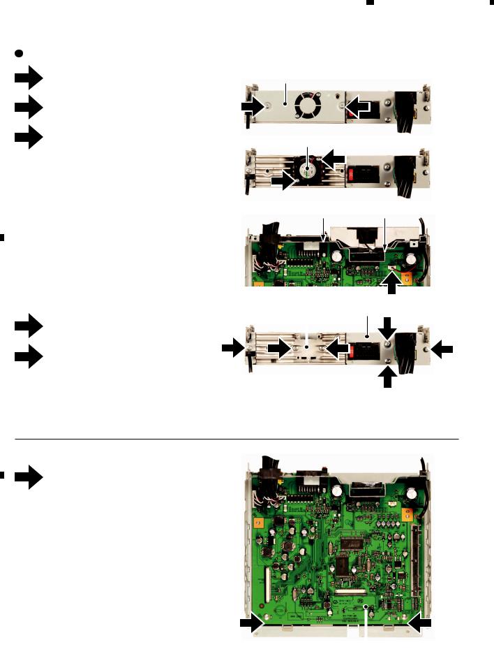
|
1 |
|
2 |
|
3 |
|
|
|
A |
Removing the Cover, Fan Motor, Heat Sink and the Holder (Fig.5) |
|
1 |
Remove the two screws and then remove |
|
|
|
the Cover. |
2 |
Remove the two screws. |
|
|
|
|
|
|
|
3 |
Disconnect the connector and then remove |
|
|
|
the Fan Motor. |
B
Attention at assembly:
Attach the Cable of Fan Motor to the latch on the Holder as shown in the right figure.
Cover
3
1
Fan Motor
2
2
Holder
C
|
|
|
|
Heat Sink |
||
4 |
Remove the two screws and then remove |
|
|
|
|
|
|
|
the Heat Sink. |
|
|
|
|
|
5 |
5 |
4 |
|
|
4 |
|
|
|||||
|
Remove the four screws and then remove |
|
|
|
|
|
|
|
|
|
|
||
|
|
|
|
|
||
the Holder.
D
4
1
latch
3
Holder
5
5
5
Fig.5
 Removing the MB PCB Assy (Fig.6)
1 Remove the two screws and then remove the MB PCB Assy.
E
|
|
|
|
|
|
1 |
|
|
1 |
|
|
||||
|
|
|
|
|
|
|
|
|
|
||||||
|
|
|
|
|
|
|
|
|
|
||||||
F |
|
|
|
|
|
|
|
|
|
|
|
|
|
||
|
|
|
|
|
|
|
MB PCB Assy |
|
|||||||
|
|
|
|
|
|
|
|
|
|
|
|||||
|
|
|
|
|
|
|
|
|
|
|
|
|
Fig.6 |
|
|
|
|
|
|
|
|
|
|
|
|
|
|
|
|
|
|
|
|
|
|
|
|
|
|
|
|
|
|
|
|
|
|
24 |
|
|
|
AVH-3500DVD/XEUC |
|
|
|
|
|
|
|
||||
|
|
|
1 |
|
2 |
|
|
|
3 |
|
|
|
4 |
|
|
|
|
|
|
|
|
|
|
|
|||||||

|
5 |
|
6 |
|
|
 Removing the Monitor Assy (Fig.7)
1 |
Remove the four screws and then remove |
|
the Cover (1). |
2 |
Disconnect the connector. |
3 |
Remove the two screws and then remove |
|
the two Guides(Right side, Left side). |
4 |
Pull out the Monitor Assy in the direction |
|
indicated by an arrow. |
|
7 |
|
8 |
|
|
|
|
A
|
Cover (1) |
|
|
1 |
|
1 |
|
1 |
2 |
|
|
|
|
||
|
|
||
|
|||
1 |
|
||
B
3 |
3 |
|
|
C
5
6
7
8
Remove the two screws.
Remove the four screws and then remove the Cover (2).
Remove the four screws.
Disconnect the connector and then remove the Monitor Assy.
4
Monitor Assy
D
5 5
7 |
8 |
|
7 |
|
||
|
|
|||||
|
|
|
|
|
||
7 |
|
|
|
|
E |
|
|
|
|
7 |
|
||
6 |
6 |
6 |
|
|
||
|
6 |
|
||||
|
|
|
|
|
|
|
|
|
|
|
Cover (2) |
|
|
|
Monitor Assy |
|
|
|||
|
|
|
||||
|
|
|
|
|
||
F
Fig.7
|
|
|
|
AVH-3500DVD/XEUC |
|
|
|
25 |
|
||
|
5 |
|
6 |
|
|
7 |
|
8 |
|
|
|
|
|
|
|
|
|
||||||

|
1 |
|
2 |
|
|
|
|
A |
Removing the TFT SMT Unit (Fig.8) |
|
|
|
|
|
1 |
Disconnect the two connectors. |
|
2 |
Remove the two screws and then remove |
|
|
the TFT SMT Unit. |
|
|
|
B
3 |
|
4 |
|
|
|
TFT SMT Unit
2 |
2 |
|
|
1
1
1
Fig.8
 Removing the Main PCB Unit and the SW PCB Unit (Fig.9)
C |
1 |
Remove the two screws. |
|
|
|
|
|
|
|
Cover |
|
|
|||
|
|
|
|
|
|
||
|
|
2 |
Remove the six screws and then remove |
1 |
|
|
1 |
|
|
|
|
|
|
||
|
|
|
the Cover. |
2 |
|
2 |
2 |
|
|
|
|
|
|||
|
|
3 |
|
|
|
||
|
|
Remove the five Gears. |
2 |
|
|
|
|
|
|
|
|
||||
|
|
|
(Pay attention not to miss the Gears because |
|
|
|
|
|
|
|
they are not secured.) |
2 |
|
|
2 |
D |
4 |
Remove the four solders. |
|
|
|
|
|
|
5 |
Remove the screw. |
3 |
||
|
|
|
|
|
||
|
|
|
|
3 |
|
|
|
|
6 |
Remove the Washer, Arm(1) and the Torsion |
|
|
|
|
|
|
|
|
||
|
|
7 |
Spring. |
|
|
|
|
|
Remove the Washer, Arm(2) and the Torsion |
|
|
|
|
|
|
|
Spring. |
|
|
|
E |
8 |
Remove the screw and then remove the |
SW PCB Unit |
|||
|
|
|
SW PCB Unit. |
|||
|
|
|
Arm(2) |
|
|
|
|
|
|
|
|
|
|
|
|
|
Attention of removing: |
|
|
|
|
|
|
As Main PCB Unit and SW PCB Unit are |
|
|
|
|
|
|
connected with FFC, Main PCB Unit and |
|
|
|
|
|
|
SW PCB Unit are removed at the same time. |
7 |
|
|
|
|
|
|
|
||
|
|
|
|
|
|
|
|
|
|
|
6 |
|
|
|
|
|
Arm(1) |
8 |
||
|
|
|
|
|
|
|
F |
|
|
|
|
|
|
3 |
3 |
3
Main PCB Unit
5
4
4
Fig.9
26 |
|
|
|
AVH-3500DVD/XEUC |
|
|
|
|
|||
|
|
1 |
|
2 |
|
|
|
3 |
|
4 |
|
|
|
|
|
|
|
|
|
||||
 Loading...