

Page 1

19554-3FR-06
PNOZ X10
4
D Betriebsanleitung
4
GB Operating instructions
4
F Manuel d'utilisation
Sicherheitsbestimmungen
• Das Gerät darf nur von Personen installiert
und in Betrieb genommen werden, die mit
dieser Betriebsanleitung und den geltenden Vorschriften über Arbeitssicherheit
und Unfallverhütung vertraut sind.
Beachten Sie die VDE- sowie die örtlichen
Vorschriften, insbesondere hinsichtlich
Schutzmaßnahmen.
• Beim Transport, bei der Lagerung und im
Betrieb die Bedingungen nach IEC 600682-6 einhalten (s. technische Daten).
• Durch Öffnen des Gehäuses oder eigenmächtige Umbauten erlischt jegliche Gewährleistung.
• Montieren Sie das Gerät in einen Schaltschrank; Staub und Feuchtigkeit können
sonst zu Beeinträchtigungen der Funktionen führen.
• Sorgen Sie an allen Ausgangskontakten
bei kapazitiven und induktiven Lasten für
eine ausreichende Schutzbeschaltung.
Bestimmungsgemäße Verwendung
Das Sicherheitsschaltgerät dient dem
sicherheitsgerichteten Unterbrechen eines
Sicherheitsstromkreises. Das Sicherheitsschaltgerät erfüllt Forderungen der
EN 60947-5-1, EN 60204-1 und VDE 0113-1
und darf eingesetzt werden in Anwendungen
mit
• Not-Halt-Tastern
• Schutztüren
Safety Regulations
• The unit may only be installed and
operated by personnel who are familiar
with both these instructions and the current
regulations for safety at work and accident
prevention. Follow CEN and local
regulations especially as regards
preventative measures.
• Transport, storage and operating conditions
should all conform to IEC 60068-2-6
(s. technical data).
• Any guarantee is void following opening of
the housing or unauthorised modifications.
• The unit should be panel mounted, otherwise dampness or dust could lead to
function impairment.
• Adequate protection must be provided on
all output contacts with capacitive and
inductive loads.
Authorised Applications
The safety relay provides a safety-related
interruption of a safety circuit. The safety
relay meets the requirements of EN 60947-51, EN 60204-1 and VDE 0113-1 and may be
used in applications with
• E-STOP pushbuttons
• Safety gates
Conseils préliminaires
• La mise en oeuvre de l’appareil doit être
effectuée par une personne spécialisée en
installations électriques, en tenant compte
des prescriptions des différentes normes
applicables (NF, EN, VDE...) notamment au
niveau des risques encourus en cas de
défaillance de l’équipement électrique.
• Respecter les exigences de la norme
IEC 60068-2-6 lors du transport, du
stockage et de l'utilisation de l'appareil.
• L’ouverture de l’appareil ou sa modification
annule automatiquement la garantie.
• L’appareil doit être monté dans une armoire; l’humidité et la poussière pouvant
entraîner des aléas de fonctionnement.
• Vérifiez que le pouvoir de coupure des
contacts de sortie est suffisant en cas de
circuits capacitifs ou inductifs.
Domaines d’utilisation
Le bloc logique de sécurité sert à interrompre
en toute sécurité un circuit de sécurité. Le
bloc logique de sécurité satisfait aux
exigences des normes EN 60947-5-1,
EN 60204-1 et VDE 0113-1 et peut être
utilisé dans des applications avec des
• poussoirs d'arrêt d'urgence
• protecteurs mobiles
Gerätebeschreibung
Das Sicherheitsschaltgerät PNOZ X10 ist in
einem P-93-Gehäuse untergebracht. Es
stehen verschiedene Varianten für den
Betrieb mit Wechselspannung und eine
Variante für den Betrieb mit Gleichspannung
zur Verfügung.
Merkmale:
• Relaisausgänge: sechs Sicherheitskontakte (Schließer) und vier Hilfskontakte
(Öffner), zwangsgeführt
• Anschlussmöglichkeit für Not-Halt-Taster,
Schutztürgrenztaster und Starttaster
• Netzanzeige
• Statusanzeige
• Rückführkreis zur Überwachung externer
Schütze
Das Schaltgerät erfüllt folgende Sicherheitsanforderungen:
• Schaltung ist redundant mit Selbstüberwachung aufgebaut
• Sicherheitseinrichtung bleibt auch bei
Ausfall eines Bauteils wirksam.
• Bei jedem Ein-Aus-Zyklus der Maschine
wird automatisch überprüft, ob die Relais
der Sicherheitseinrichtung richtig öffnen
und schließen.
• Der AC-Teil hat einen kurzschlussfesten
Netztransformator, der DC-Teil eine
elektronische Sicherung.
Description
The Safety Relay PNOZ X10 is enclosed in a
P-93 housing. There are different versions
available for AC operation and one for DC
operation.
Features:
• Relay outputs: six safety contacts (N/O)
and four auxiliary contacts (N/C), positiveguided.
• Connections for Emergency Stop Button,
Safety Gate Limit Switch and Reset
Button.
• Power indicator
• Status Indicators.
• Feedback Control Loop for monitoring of
external contactors/relays.
The relay complies with the following safety
requirements:
• The circuit is redundant with built-in selfmonitoring.
• The safety function remains effective in the
case of a component failure.
• The correct opening and closing of the
safety function relays is tested automatically in each on-off cycle.
• AC relays are fitted with a short-circuit
proof power transformer. DC relays have
an electronic fuse.
Description de l’appareil
Inséré dans un boîtier P93, le bloc logique de
sécurité PNOZ X10 est disponible en
différentes versions pour les tensions
d’alimentation alternatives et une version en
alimentation continue (24 V DC).
Autres particularités :
• Sorties disponibles : 6 contacts à fermeture de sécurité et 4 contacts à ouverture
pour signalisation
• Bornes de raccordement pour poussoirs
AU, détecteurs de position et poussoir de
validation
• LEDs de visualisation des canaux d’entrée
et de la tension d’alimentation
• Boucle de retour pour l’auto-contrôle des
contacteurs externes
Le relais PNOZ X10 répond aux exigences
suivantes :
• conception redondante avec autosurveillance
• sécurité garantie même en cas de
défaillance d’un composant
• test cyclique (ouverture/fermeture des
relais internes) à chaque cycle Marche/
Arrêt de la machine
• L'alimentation AC est équipé d'un
transformateur protégé contre les courtscircuits. L'alimentation DC dispose d'un
fusible électronique.
- 1 -
Page 2
Funktionsbeschreibung
Das Schaltgerät PNOZ X10 dient dem
sicherheitsgerichteten Unterbrechen eines
Sicherheitsstromkreises. Nach Anlegen der
Versorgungsspannung, Brücke zwischen
Y1-Y2 und S12 (S33)-S34 sowie geöffnetem
Eingangskreis geht Relais K3 in Wirkstellung.
•
Eingangskreis geschlossen (z. B. Not-HaltTaster nicht betätigt)
Relais K1 und K2 gehen über die Schließer K3.1 und K3.2 in Wirkstellung und
halten sich selbst über K1.1 bzw. K2.1. Die
Statusanzeigen leuchten. Durch Öffnen
der Kontakte K1.2 und K2.2 geht K3 nach
Ablauf der Rückfallverzögerung in
Ruhestellung. Die Sicherheitskontakte
(13-14/23-24/33-34/43-44/53-54/63-64)
sind geschlossen, die Hilfskontakte (71-72/
81-82/91-92/01-02) sind geöffnet.
•
Eingangskreis wird geöffnet (z. B. NotHalt-Taster betätigt)
K1 und K2 fallen in die Ruhestellung
zurück. Die Sicherheitskontakte (13-14/2324/33-34/43-44/53-54/63-64) werden
redundant geöffnet, die Hilfskontakte
(71-72/81-82/91-92/01-02) geschlossen.
Start mit Überwachung (Taster im Startkreis und Y1-S37 geschlossen)
Bei Betätigen des Starttasters zieht Relais K3
an und hält sich selbst. Erst nach Loslassen
des Starttasters ist das Gerät betriebsbereit.
Relais K3 fällt ab.
Function Description
The relay PNOZ X10 provides a safetyoriented interruption of a safety circuit. When
the operating voltage is supplied, Y1 - Y2
and S12 (S33) - S34 are bridged and the
input circuit is closed, relay K3 energises.
• Input circuit closed (e.g. Emergency Stop
Button not activated):
Relay K1 and K2 energise via the N/O
K3.1 and K3.2 and latch via K1.1/K2.1.
The status indicators illuminate. By
opening the contacts K1.1 and K2.2, K3
de-energises following the delay-on deenergisation. The safety contacts (13-14/
23-24/33-34/43-44/53-54/63-64) are
closed, the auxiliary contacts (71-72/81-82/
91-92/01-02) are opened.
• Input circuit opened (e.g. Emergency Stop
Button activated):
K1 and K2 de-energise. The safety
contacts (13-14/23-24/33-34/43-44/53-54/
63-64) are opened redundantly, the
auxiliary contacts (71-72/81-82/91-92/01-
02) are closed.
Reset with monitoring (Button in reset
circuit and Y1-S37 linked)
By pressing the reset button, relay K3
energises and retains itself. Only after
releasing the reset button is the unit ready for
operation. Relay K3 de-energises.
Description du fonctionnement
Le relais PNOZ X10 assure de façon sure,
l’ouverture d’un circuit de sécurité. A la mise
sous tension du relais (A1-A2), si Y1-Y2 et
S12 (S33)-S34 sont pontés et les canaux
d’entrée ouverts, le relais K3 colle.
•
Fermeture des canaux d’entrée
(par ex. AU non actionné) :
les relais K1 et K2 collent par l’intermédiaire
des contacts K3.1 et K3.2 et s’automaintiennent par K1.1 et K2.1. Les LEDs de
visualisation sont allumées. L’ouverture des
contacts K1.2 et K2.2 fait retomber le relais
K3. Les contacts de sortie de sécurité (1314/23-24/33-34/43-44/53-54 et 63-64) se
ferment, les contacts d’information 71-72/
81-82/91-92 et 01-02 s’ouvrent.
• Ouverture des canaux d’entrée (par ex.
action sur AU):
K1 et K2 retombent. Les contacts de sortie
(13-14/23-24/33-34/43-44/53-54/63-64)
s’ouvrent de façon redondante, les contacts
d’information (71-72/81-82/91-92/01-02) se
ferment.
Surveillance du poussoir de réarmement
(pontage des bornes S1-Y37)
Une action sur le poussoir de réarmement fait
monter le relais K3 qui s'auto-maintient. Le
PNOZ X10 n'est activé qu'au relâchement du
poussoir de réarmement. Le relais K3
retombe.
U
B
A2 (L-)A1 (L+)
F1
~
G1
S11 13 23 33 71
+
=
S33
Y3
S11 S21 Y2
S12S12 S22
K3.1 K3.2
K1.1
K1
K2.1
K2
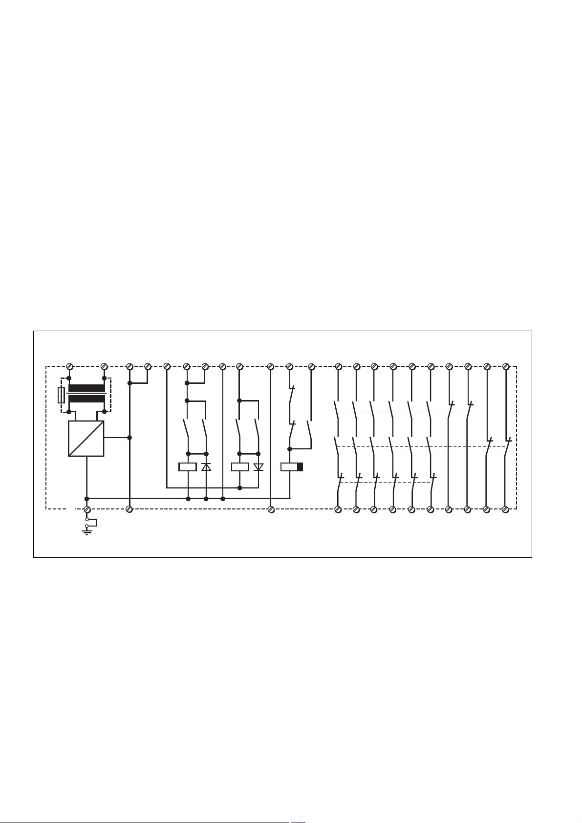
*
Fig. 1: Innenschaltbild/Internal Wiring Diagram/Schéma de principe
Betriebsarten:
• Einkanaliger Betrieb: Eingangsbeschaltung
nach VDE 0113 und EN 60204-1, keine
Redundanz im Eingangskreis, Erdschlüsse
im Tasterkreis werden erkannt.
• Zweikanaliger Betrieb: Redundanter Eingangskreis, Erdschlüsse im Tasterkreis
und Querschlüsse zwischen den Tasterkontakten werden erkannt.
• Automatischer Start: Gerät ist aktiv, sobald
Eingangskreis geschlossen.
• Manueller Start: Gerät ist erst dann aktiv,
wenn ein Starttaster betätigt wird.
• Manueller Start mit Überwachung: Gerät
ist erst aktiv, wenn der Starttaster betätigt
und wieder losgelassen wurde.
• Kontaktvervielfachung und -verstärkung
durch Anschluss von externen Schützen.
Operating Modes
• Single-channel operation: Input wiring
according to EN 60204-1, no redundancy in
the input circuit, earth faults are detected in
the emergency stop circuit.
• Two-channel operation: Redundancy in the
input circuit, earth faults in the emergency
stop circuit and shorts across the emergency stop pushbutton will be detected.
• Automatic reset: Unit is active as soon as
the input circuit is closed.
• Manual reset: Unit is only active when a
start button has been pressed.
• Manual reset with monitoring: Unit is only
activated, when the reset button ist pressed
and then released.
• Increase in the number of available contacts
by connection of external contactors/relays.
Y1
S34
K1.2
K2.2
K3
S37
K1
K3
K2
K3
14 24 34 72
4344535463
Modes de fonctionnement
• Commande par 1 canal: conforme aux
prescriptions de la EN 60204-1, pas de
redondance dans le circuit d’entrée, la mise
à la terre du circuit d’entrée est détectée.
• Commande par 2 canaux: circuit d’entrée
redondant, la mise à la terre et les courtscircuits entre les contacts sont détectés.
• Réarmement automatique : le relais est
activé dès la fermeture des canaux d’entrée.
• Réarmement manuel: le relais n’est activé
qu’après une impulsion sur un poussoir de
validation.
• Surveillance de circuit de réarmement : le
relais n'est activé qu'après le relâchement
du poussoir de validation.
• Augmentation du nombre de contacts ou du
pouvoir de coupure par l’utilisation de
contacteurs externes.
818291 01
64
92
02
- 2 -
Page 3

Montage
Das Sicherheitsschaltgerät muss in einen
Schaltschrank mit einer Schutzart von mind.
IP54 eingebaut werden. Zur Befestigung auf
einer Normschiene dient ein Rastelement auf
der Rückseite des Geräts.
Sichern Sie das Gerät bei Montage auf einer
senkrechten Tragschiene (35 mm) durch ein
Halteelement wie z. B. Endhalter oder
Endwinkel.
Installation
The safety relay must be panel mounted
(min. IP54). There is a notch on the rear of
the unit for DIN-Rail attachment.
If the unit is installed on a vertical mounting
rail (35 mm), ensure it is secured using a
fixing bracket such as end bracket.
Montage
Le relais doit être monté en armoire ayant un
indice de protection mini IP54. Sa face
arrière permet un montage sur rail DIN.
Immobilisez l'appareil monté sur un rail DIN
vertical (35 mm) à l'aide d'un élément de
maintien comme par ex. un support ou une
équerre terminale.
Inbetriebnahme
Beachten Sie bei der Inbetriebnahme:
• Nur die Ausgangskontakte 13-14/23-24/
33-34/43-44/53-54/63-64 sind Sicherheitskontakte. Ausgangskontakte 71-72/81-82/
91-92/01-02 sind Hilfskontakte (z. B. für
Anzeige).
• Vor die Ausgangskontakte eine
Sicherung (s. technische Daten)
schalten, um das Verschweißen der
Kontakte zu verhindern.
• Berechnung der max. Leitungslänge I
(Eingangskreis):
R
I
max
R
(Eingangskreis)
lmax
=
Rl / km
= max. Gesamtleitungswiderstand
lmax
Rl /km = Leitungswiderstand/km
• Da die Funktion Querschlusserkennung
nicht einfehlersicher ist, wird sie von Pilz
während der Endkontrolle geprüft. Eine
Überprüfung nach der Installation des
Geräts ist wie folgt möglich:
1. Gerät betriebsbereit (Ausgangskontakte
geschlossen)
2. Die Testklemmen S12-S22 zur
Querschlussprüfung kurzschließen.
3. Die Sicherung im Gerät muss auslösen
und die Ausgangskontakte öffnen. Leitungslängen in der Größenordnung der
Maximallänge können das Auslösen der
Sicherung um bis zu 2 Minuten verzögern.
4.
Sicherung wieder zurücksetzen: den
Kurzschluss entfernen und die Versorgungsspannung für ca. 1 Minute
ten.
• Bei AC-Geräten kann kein zusätzlicher
Verbraucher verwendet werden. Bei DCGeräten zusätzliche Verbraucher mit max.
250 mA.
• Leitungsmaterial aus Kupferdraht mit einer
Temperaturbeständigkeit von 60/75 °C
verwenden.
• Sorgen Sie beim Anschluss von magnetisch wirkenden, auf Reedkontakten
basierenden Näherungsschaltern dafür,
dass der max. Einschaltspitzenstrom (am
Eingangskreis) den Näherungsschalter
nicht überlastet.
• Angaben im Kapitel „Technische Daten“
unbedingt einhalten.
Ablauf:
• Versorgungsspannung an Klemmen A1 (+)
und A2 (-) anlegen.
- DC: Klemme A2 (-) mit geerdeter Seite
der Versorgungsspannung verbinden.
- AC: Betriebserdungsklemme mit
Schutzleitersystem verbinden.
• Eingangskreis
- Einkanalig: S12-Y3 und S21-S22
brücken. Öffnerkontakt von Auslöseelement an S12 und S11 anschließen.
- Zweikanalig ohne Querschluss-
erkennung: S21- S22 brücken; Öffnerkontakt von Auslöseelement an S11S12/S11-Y3 anschließen.
max
abschal-
Operation
Please note for operation:
• Only the output contacts 13-14/23-24/3334/43-44/53-54/63-64 are safety contacts.
Output contacts 71-72/81-82/91-92/01-02
are auxiliary contacts (e.g. for a display).
• To prevent contact welding, a fuse
should be connected before the output
contacts (see technical details).
• Calculate the max. Cable runs I
circuit)
R
I
max
R
circuit)
lmax
=
Rl / km
= Max. Total cable resistance (Input
lmax
Rl /km = Cable resistance/km
• As the function for detecting shorts across
the inputs is not failsafe, it is tested by Pilz
during the final control check. However, a
test is possible after installing the unit and
it can be carried out as follows:
1. Unit ready for operation (output contacts
closed)
2. Short circuit the test (connection)
terminals S12-S22 for detecting shorts
across the inputs.
3. The unit‘s fuse must be triggered and
the output contacts must open. Cable
lengths in the scale of the maximum length
can delay the fuse triggering for up to 2
minutes.
4. Reset the fuse: remove the short circuit
and switch off the operating voltage for
approx. 1 minute.
• When your external device (limit switch
etc.) has a current consumption, with DC
units this must not exceed 250 mA. With
AC units no load is permitted.
• Use copper wiring that will withstand
60/75 °C
• When connecting magnetically operated,
reed proximity switches, ensure that the
max. peak inrush current (on the input
circuit) does not overload the proximity
switch.
• Important details in the section "Technical
Data“ should be noted and adhered to.
To operate:
• Supply operating voltage to terminals
A1 (+) and A2 (-).
- DC: Connect terminal A2 (-) with the
earthed side of the operating voltage.
- AC: Connect the operating earth terminal
with the ground earth.
• Input circuit
- Single-channel: Bridge S12 - Y3 & S21 -
S22. Connect N/C contact from trigger
element (e.g. E-Stop) to S12 and S11.
- Two-channel without detection of shorts
across the contacts: Bridge S21 -S22.
Connect N/C contact from trigger element
(e.g. E-Stop) to S11 - S12/S11 - Y3
max
(Input
Mise en oeuvre
Remarques préliminaires :
• Seuls les contacts 13-14, 23-24, 33-34,
43-44, 53-54, 63-64 sont des contacts de
sécurité. Les contacts 71-72, 81-82, 9192, 01-02 sont des contacts d’information
(ex. voyant).
• Raccordez un fusible (voir les
caractéristiques techniques) avant les
contacts de sortie afin d’éliminer tout
risque de fusion.
• Calculer les longueurs de câblage max
I
(Circuits d’entrée):
max
R
I
max
R
(Circuits d’entrée)
Rl /km = résistivité de câblage/km
• La fonction de détection de court-circuit est
testé par Pilz lors du contrôle final. Un test
sur site est possible de la façon suivante :
1. Appareil en fonction (contacts de sortie
fermés)
2. Court-circuiter les bornes de
raccordement nécessaires au test S12-S22
3. Le fusible interne du relais doit
déclencher et les contacts de sortie
doivent s‘ouvrir. Le temps de réponse du
fuisible peut aller jusqu‘à 2 min. si les
longueurs de câblage sont proches des
valeurs maximales.
4. Réarmement du fusible : enlever le
court-circuit et couper l‘alimentation du
relais pendant au moins 1 min.
• Pour les relais AC, aucun autre utilisateur
ne peut être alimenté. Pour les relais en
DC, utilisateur suppl. possible jusqu’à 250
mA max.
• Utiliser uniquement des fils de cablâge en
cuivre 60/75 °C.
• Lors du raccordement de détecteurs de
proximité magnétiques, basés sur des
contacts Reed, veuillez vous assurer que
le courant de crête max. à la mise sous
tension (sur le circuit d'entrée) ne
surcharge pas les détecteurs de proximité.
• Respecter les données indiquées dans le
chap. „Caractéristiques techniques“.
Mise en oeuvre :
• Amener la tension d’alimentation sur A1
et A2
- DC : borne A2 à relier au „-“
- AC : relier la borne terre
• Circuits d’entrée
- Commande par 1 canal : câblage du
- Commande par 2 canaux sans détection
lmax
=
Rl / km
= résistivité de câblage totale max.
lmax
contact à ouverture entre S11 et S12,
pontage de S21-S22 et S12-Y3
de courts-circuits : câblage des contacts
à ouverture entre S11-S12/S11-Y3 ,
pontage de S21-S22
- 3 -
Page 4

- Zweikanalig mit Querschlusserkennung:
S11 S21
S12 Y2
S34
S22
Y3
S11
S12 Y1
S1
S3
Y1
S37
S11-Y3 brücken; Öffnerkontakt von
Auslöseelement an S11-S12/S21-S22
anschließen.
• Startkreis:
Einkanaliger Betrieb und zweikanaliger
Betrieb ohne Querschlusserkennung
(zweikanalig gegen +24 V geschaltet):
- Automatischer Start: S33-S34 brücken.
- Manueller Start: Taster zwischen S33-S34
- Manueller Start mit Überwachung: Taster
zwischen S33-S34, Y1-S37 brücken.
Zweikanaliger Betrieb mit Querschlusserkennung:
- Automatischer Start: S12-S34 brücken.
- Manueller Start: Taster zwischen S12-S34
- Manueller Start mit Überwachung: Taster
zwischen S12-S34, Y1-S37 brücken.
• Rückführkreis:
Brücke an Y1-Y2 oder externe Schütze
anschließen.
Die Sicherheitskontakte sind aktiviert (geschlossen) und die Hilfskontakte (71-72/81-82/
91-92/01-02) sind geöffnet. Die Statusanzeigen
von Kanal 1 und Kanal 2 leuchten. Das Gerät
ist betriebsbereit.
Wird der Eingangskreis geöffnet, öffnen die
Sicherheitskontakte 13-14/23-24/33-34/43-44/
53-54/63-64 und die Hilfskontakte 71-72/81-82/
91-92/01-02 schließen. Die Statusanzeige
erlischt.
Wieder aktivieren
• Eingangskreis schließen.
• Bei manuellem Start zusätzlich Taster
zwischen S12 (S33) und S34 betätigen, bei
manuellem Start mit Überwachung Taster
betätigen und wieder loslassen.
Die Statusanzeigen leuchten wieder, die
Sicherheitskontakte sind geschlossen.
- Two-channel with detection of shorts
across the contacts: Bridge S11 -Y3.
Connect N/C contact from trigger element
(e.g. E-Stop) to S11 - S12/S21 - S22.
• Reset circuit:
Singel-channel operation and dual-channel
operation without detection of shorts across
the contacts (dual-channel switched against
+24 V DC):
- Automatic reset: Bridge S33-S34
- Manual reset: Connect button to S33-S34
- Manual reset with monitoring: Connect
button to S33-S34, bridge Y1-S37.
Dual-channel operation with detection of
shorts across the contacts:
- Automatic reset: Bridge S12-S34
- Manual reset: Connect button to S12-S34
- Manual reset with monitoring: Connect
button to S12-S34, bridge Y1-S37.
• Feedback control loop:
Bridge Y1 - Y2 or connect external N/C
contacts in series from other devices .
The safety contacts are activated (closed)
and the auxiliary contacts (71-72/81-82/9192/01-02) are open. The status indicators
from channel 1 and channel 2 are
illuminated. The unit is ready for operation.
If the input circuit is opened, the safety
contacts 13-14/23-24/33-34/43-44/53-54/6364 open and the auxiliary contacts 71-72/8182/91-92/01-02 close. The status indicator
goes out.
Reactivation
• Close the input circuit.
• For manual reset, momentary closure of the
button between S12 (S33) and S34 must be
pressed; for manual reset with monitoring,
press the button and release again.
The status indicators light up again, the
safety contacts are closed.
- Commande par 2 canaux avec détection
de courts-circuits : câblage des contacts
à ouverture entre S11-S12/S21-S22 ,
pontage de S11-Y3
• Circuit de réarmement:
Commande mono-canal et en 2 canaux
sans détection de courts-circuits entre les
canaux (les 2 canaux reliés au +24 V):
- Réarmement automatique: pontage des
bornes S33-S34
- Réarmement manuel: câblage d’un
poussoir sur S33-S34
- Surveillance du circuit de réarmement:
câblage d'un poussoir sur S33-S34 et
pontage des bornes Y1-S37 .
Commande en 2 canaux avec détection de
courts-circuits:
- Réarmement automatique: pontage des
bornes S12-S34
- Réarmement manuel: câblage d’un
poussoir sur S12-S34
- Surveillance du circuit de réarmement:
câblage d'un poussoir sur S12-S34 et
pontage des bornes Y1-S37.
• Boucle de retour:
Pontage de Y1-Y2 ou branchement des
contacts externes
Les contacts de sortie se ferment et les
contacts d’info (71-72/81-82/91-92/01-02)
s’ouvrent. Les LEDs de visualisation des
canaux 1 et 2 sont allumées. L’appareil est
prêt à fonctionner.
Si le circuit d’entrée est ouvert, les contacts de
sortie 13-14/23-24/33-34/43-44/53-54/63-64
s’ouvrent et les contacts d’inform 71-72/81-82/
91-92/01-02 se ferment. Les LEDs s’éteignent.
Remise en route :
• fermer le(s) circuit(s) d’entrée
• en cas de réarmement manuel, appuyer
sur le poussoir de validation entre S12
(S33)-S34. En cas de surveillance du
circuit de réarmement, appuyer puis
relacher le poussoir de validation.
Les affichages d'état s'allument à nouveau.
Les contacts de sécurité sont fermées.
Anwendung
In Fig. 2 ... Fig. 10 sind Anschlussbeispiele für
Not-Halt-Beschaltung
Fig. 6: Gleichzeitigkeit: 150 ms
S11 S21 S33
Y3
S1
S12
S12
Fig. 2: Eingangskreis einkanalig/Singlechannel input circuit/Commande par 1 canal
S3
Y1
Y2
S34S22
Application
In Fig. 2 ... Fig. 10 are connection examples
for Emergency Stop.
Fig. 6: Simultaneity 150 ms by Safety Gate
Control
S11 S11
S1
S3
Y3
S12 Y2
Fig. 3: Eingangskreis zweikanalig ohne
Querschlusserkennung/Two-channel input
circuit; no short-circuit recognition/Commande
par 2 canaux sans détection des c. c.
S33 Y1
S34
S21
S22
Utilisation
Dans les figures 2 à 10 sont représentés les
différents cablages possibles du PNOZ X10
Fig. 6: Désynchronisme: 150 ms
Fig. 4: Eingangskreis zweikanalig, überwachter Start mit Querschlusserkennung/Twochannel input circuit, monitored reset with
short-circuit recognition/Commande par 2
canaux, surveillance du poussoir de
validation avec détection des c. c.
- 4 -
Page 5

S11
14
K4 K5
13
Y1 Y2
K4
K5
1L1
1L2
S12
S1
S21
S3
S22
S33 Y1
S34
Y2
Y3
S12
Fig. 5: Schutztürsteuerung einkanalig/Single
channel safety gate control/Surveillance de
protecteur, commande par 1 canal
S33
S34
S1
S2
S21
S22
Y1
Y2
S11
Y3
S11
S12
Fig. 6: Schutztürsteuerung zweikanalig,
automatischer Start/Two channel safety gate
control, automatic reset/Surveillance de
protecteur, commande par 2 canaux,
validation automatique
S12 (S33)
S34
Y1
S37
Fig. 7: Automatischer Start/Automatic reset/
Rearmement automatique
S12 (S33)
S3
Fig. 8: Manueller Start/Manual reset/
Rearmement manuel
S34
Y1
S37
Fig. 9: Manueller Start mit Überwachung/
Manual reset with monitoring/Surveillance de
circuit de réarmement
S1/S2: Not-Halt- bzw. Schutztürschalter/Emergency Stop Button,
Safety Gate Limit Switch/Poussoir AU, détecteurs de
position
S3: Starttaster/Reset button/Poussoir de réarmement
Fehler - Störungen
• Erdschluss
Die Versorgungsspannung bricht zusammen und die Sicherheitskontakte werden
über eine elektronische Sicherung
geöffnet. Nach Wegfall der Störungsursache und Abschalten der Versorgungsspannung für ca. 1 Minute ist das Gerät
wieder betriebsbereit.
• Fehlfunktionen der Kontakte: Bei verschweißten Kontakten ist nach Öffnen des
Eingangskreises keine neue Aktivierung
möglich.
• Nur eine oder keine Leuchtdiode leuchtet:
Externer Beschaltungsfehler oder interner
Faults/Disturbances
• Earth fault
Supply voltage fails and the safety
contacts are opened via an electronic fuse.
Once the cause of the fault has been
removed and operating voltage is switched
off, the unit will be ready for operation after
approximately 1 minute.
• Faulty contact functions: In the case of
welded contacts, no further activation is
possible following an opening of the input
circuit.
• Only one or no LED illuminates: An
external wiring fault or an internal fault is
present.
Fehler liegt vor.
S12 (S33)
S3
S34
Y1
S37
Fig. 10: Anschlussbeispiel für externe
Schütze/ Connection example for external
Contactors, relays/Branchement contacteurs
externes
betätigtes Element/Switch activated/élément actionné
Tür nicht geschlossen/Gate open/porte ouverte
Tür geschlossen/Gate closed/porte fermée
Erreurs-Défaillances
• Défaut de masse
La tension d’alimentation chute et les
contacts de sécurité sont ouverts par un
fusible électronique. Une fois la cause du
défaut éliminée et la tension d’alimentation
coupée, l’appareil est à nouveau prêt à
fonctionner après environ 1 minute.
• Défaut de fonctionnement des contacts
internes : en cas de soudage d’un contact
lors de l’ouverture du circuit d’entrée, un
nouvel réarmement est impossible.
• Seule une ou pas de LED est allumée :
erreur de câblage externe ou défaut
interne du boîtier
Abmessungen in mm (")/Dimensions in mm (")/Dimensions en mm (")
75 (2.95")
87 (3.42")
121 (4.76")
- 5 -
90 (3.54")
Page 6

Technische Daten
Technical details
Caractéristiques techniques
Elektrische Daten
Versorgungsspannung U
Spannungstoleranz U
Leistungsaufnahme bei U
B
B
B
Frequenzbereich
Restwelligkeit
Spannung und Strom an
Eingangskreis
Startkreis
Rückführkreis
Anzahl der Ausgangskontakte
Sicherheitskontakte (S)
Hilfskontakte (Ö)
Gebrauchskategorie nach
EN 60947-4-1
AC1: 240 V
AC1: 400 V
DC 1: 24 V
EN 60947-5-1
AC 15: 230 V
(DC13: 6 Schaltspiele/Min.): 24 V
Kontaktmaterial
Kontaktabsicherung extern
EN 60947-5-1 (IK = 1 kA)
Schmelzsicherung
Sicherungsautomat,
Charakteristik B/C
Max. Gesamtleitungswiderstand
R
Imax
Eingangskreise
einkanalig
zweikanalig ohne Querschluss-
erkennung
zweikanalig mit
Querschlusserkennung
Min. Eingangswiderstand im
Einschaltmoment
Sicherheitstechnische Kenndaten
der Sicherheitsausgänge
PL nach EN ISO 13849-1
Kategorie nach EN 954-1
SIL CL nach EN IEC 62061
PFH nach EN IEC 62061
SIL nach IEC 61511
PFD nach IEC 61511
tM in Jahren
Zeiten
Einschaltverzögerung
automatischer Start
automatischer Start nach Netz-Ein
manueller Start
überwachter Start
Rückfallverzögerung
bei Not-Halt
bei Netzausfall
Wiederbereitschaftszeit bei max.
Schaltfrequenz 1/s
nach Not-Halt
nach Netzausfall
Gleichzeitigkeit Kanal 1 und 2
Electrical data
Supply voltage U
Voltage tolerance U
Power consumption at U
B
B
B
Frequency Range
Residual ripple
Voltage and current at
input circuit
reset circuit
feedback loop
Number of output contacts
Safety contacts (S)
Auxilliary contacts N/C
Utilization category in accordance with
EN 60947-4-1
AC1: 240 V
AC1: 400 V
DC 1: 24 V
EN 60947-5-1
AC 15: 230 V
(DC13: 6 cycles/min): 24 V
Contact material
External contact fuse protection
EN 60947-5-1 (IK = 1 kA)
blow-out fuse
Circuit breaker,
characteristic B/C
Max. overall cable resistance
R
lmax
input circuit
single-channel
dual-channel without detection of
shorts across contacts
dual-channel with detection of
shorts across contacts
Min. input resistance in the starting
torque
Safety-related characteristics of
the safety outputs
PL in accordance with
EN ISO 13849-1
Category in accordance with
EN 954-1
SIL CL in accordance with
EN IEC 62061
PFH in accordance with
EN IEC 62061
SIL in accordance with IEC 61511
PFD in accordance with IEC 61511
tM in years
Times
Switch-on delay
Automatic reset
Automatic reset after Power-ON
Manual reset
Monitored manual reset
Delay-on de-energisation
at E-STOP
with power failure
Recovery time at max. switching
frequency 1/s
after E-STOP
after power failure
Simultaneity channel 1 and 2
Données électriques
Tension d’alimentation U
B
Plage de la tension d'alimentation U
Consommation pour U
B
Fréquence
Ondulation résiduelle
Tension et courant sur
circuit d’entrée
circuit de réarmement
boucle de retour
Nombre de contacts de sortie
Contacts de sécurité (F)
Contacts auxilliaires
Catégorie d’utilisation selon
EN 60947-4-1
AC1: 240 V
AC1: 400 V
DC 1: 24 V
EN 60947-5-1
AC 15: 230 V
(DC13: 6 manoeuvres/min) : 24 V
Matériau contact
Protection des contacts externe
EN 60947-5-1 (IK = 1 kA)
fusible
Disjoncteur,
caractéristique B/C
Résistance max. de l'ensemble du
câblage R
circuit d’entrée
lmax
commande par 1 canal
Commande par 2 canaux sans
détection des court-circuits
Commande par 2 canaux avec
détection des court-circuits
Résistance d'entrée min. au moment
de la mise en marche
Caractéristiques techniques de
sécurité des sorties de sécurité
PL selon EN ISO 13849-1
Catégorie selon EN 954-1
SIL CL selon EN IEC 62061
PFH selon EN IEC 62061
SIL selon IEC 61511
PFD selon IEC 61511
tM en années
Temporisations
Temps de réarmement
Réarmement automatique
Réarmement automatique après
mise sous tension
Réarmement manuel
Réarmement manuel auto-contrôlé
Temps de retombée
en cas d'arrêt d'urgence
en cas de coupure d'alimentation
Temps de remise en service pour une
fréquence de commutation max. de 1/s
après un arrêt d'urgence
après une coupure d'alimentation
Désynchronisme canal 1 et 2
AC: 24 V/42 V/110 - 120 V/
230 - 240 V, DC: 24 V
-15 ... +10 %
B
UB DC: 5,5 W
UB AC: 10,0 VA
AC: 50 ... 60 Hz
DC: 160%
24 V DC, 50 mA
24 V DC, 100 mA
24 V DC, 100 mA
6
4
I
: 0,01 A, I
min
P
: 2000 VA
max
I
: 0,01 A, I
min
P
: 2000 VA
max
I
: 0,01 A, I
min
P
: 200 W
max
I
: 5,0 A
max
I
: 7,0 A
max
max
max
max
: 8,0 A,
: 5,0 A,
: 8,0 A,
AgSnO2+ 0,2 µm Au
10 A link/quick acting/rapide
6 A träge/slow acting/
normal
24 V AC/DC, 6 A
45 Ohm
90 Ohm
15 Ohm
89 Ohm
PL e (Cat. 4)
Cat. 4
SIL CL 3
2,31E-09
SIL 3
2,03E-06
20
typ. 190 ms, max. 250 ms
typ. 200 ms, max. 300 ms
typ. 200 ms, max. 250 ms
typ. 165 ms, max. 220 ms
typ. 20 ms, max. 30 ms
typ. 170 ms, max. 250 ms
50 ms
300 ms
150 ms
- 6 -
Page 7

Min. Startimpulsdauer bei
überwachtem Start
Überbrückung bei Spannungseinbrüchen
Umweltdaten
EMV
Schwingungen nach EN 60068-2-6
Frequenz
Amplitude
Klimabeanspruchung
Luft- und Kriechstrecken nach
EN 60947-1
Verschmutzungsgrad
Überspannungskategorie
Bemessungsisolationsspannung
Bemessungsstoßspannungs-
festigkeit
Umgebungstemperatur
Lagertemperatur
Schutzart
Einbauraum (z. B. Schaltschrank)
Gehäuse
Klemmenbereich
Mechanische Daten
Gehäusematerial
Gehäuse
Front
Querschnitt des Außenleiters
(Schraubklemmen)
1 Leiter, flexibel
2 Leiter gleichen Querschnitts,
flexibel mit Aderendhülse, ohne
Kunststoffhülse
ohne Aderendhülse oder mit TWIN-
Aderendhülse
Anzugsdrehmoment für
Anschlussklemmen (Schrauben)
Einbaulage
Abmessungen H x B x T
Gewicht
Min. start pulse duration with a
monitored reset
Supply interruption before
de-energisation
Environmental data
EMC
Vibration to EN 60068-2-6
Frequency
Amplitude
Climate Suitability
Airgap Creepage in accordance
with EN 60947-1
Pollution degree
Overvoltage category
Rated insulation voltage
Rated impulse withstand voltage
Ambient temperature
Storage temperature
Protection type
Mounting (eg. cabinet)
Housing
Terminals
Mechanical data
Housing material
Housing
Front
Cable cross section (screw terminals)
1 core, flexible
2 core, same cross section flexible
with crimp connectors, without
insulating sleeve
without crimp connectors or with
TWIN crimp connectors
Torque setting for connection
terminal screw
Fitting position
Dimensions H x W x D
Weight
Durée minimale de l'impulsion pour
un réarmement auto-contrôlé
Tenue aux micro-coupures
Données sur l'environnement
CEM
Vibrations selon EN 60068-2-6
Fréquences
Amplitude
Conditions climatiques
Cheminement et claquage selon
EN 60947-1
Niveau d'encrassement
Catégorie de surtensions
Tension assignée d'isolement
Tension assignée de tenue aux
chocs
Température d’utilisation
Température de stockage
Indice de protection
Lieu d'implantation (ex. armoire)
Boîtier
Bornes
Données mécaniques
Matériau du boîtier
Boîtier
Face avant
Capacité de raccordement (borniers
à vis)
1 conducteur souple
2 conducteurs de même diamètre
souple avec embout, sans chapeau
plastique
souple sans embout ou avec
embout TWIN
Couple de serrage (bornier)
Position de montage
Dimensions H x P x L
Poids
50 ms
35 ms
EN 60947-5-1, EN 61000-6-2
10-55 Hz
0,35 mm
EN 60068-2-78
2
III
250 V
4 kV
-10 ... + 55 °C
-40 ... +85 °C
IP54
IP40
IP20
PPO UL 94 V0
ABS UL 94 V0
0,2 ... 4,0 mm2, 24 - 10 AWG
0,2 ... 2,5 mm2, 24 - 14 AWG
0,2 ... 2,5 mm2, 24 - 14 AWG
0,6 Nm
beliebig/any/indifférente
87 x 90 x 121 mm
540 g (UB DC)
720 g (UB AC)
Es gelten die 2009-04 aktuellen Ausgaben
der Normen.
The version of the standards current at
2009-04 shall apply.
Se référer à la version des normes en vigeur
au 2009-04.
Konventioneller thermischer Strom bei gleichzeitiger Belastung mehrerer Kontakte/Conventional thermal current while
loading several contacts/Courant thermique conventionnel en cas de charge sur plusieurs contacts (AC1, DC1)
Anzahl der Kontakte/number of contacts/nombre des contacts 6 54321
Ith (A) bei Versorgungsspannung AC/with operating voltage AC/
pour tension d’alimentation AC 4 4,4 4,9 5,6 7 8
Ith (A) bei Versorgungsspannung DC/with operating voltage DC/
pour tension d’alimentation DC 5 5,4 6,1 7 8 8
Um ein Versagen der Geräte zu verhindern,
an allen Ausgangskontakten für eine ausreichende Funkenlöschung sorgen. Bei
kapazitiven Lasten sind eventuell auftretende
Stromspitzen zu beachten. Bei DC-Schützen
Freilaufdioden zur Funkenlöschung einsetzen,
um die Lebendauer der Schütze zu erhöhen.
To prevent failure of the unit, all output
contacts should be fused adequately. With
capacative loads, possible current peaks are
to be avoided. With DC contactors/relays
use suitable spark suppression to ensure
extended life of the contactors/relays.
Prévoir un dispositif d’extinction d’arc sur les
contacts de sortie pour éviter un éventuel
disfonctionnement du relais.
Tenir compte des pointes d’intensité en cas
de charge capacitive. Equiper les
contacteurs DC de diodes de roue libre .
- 7 -
Page 8

N
b
t
i
b
t
(A)
Bestelldaten/Order reference/Caractéristiques
Typ/
Type/
Type
PNOZ X10
PNOZ X10
PNOZ X10
PNOZ X10
PNOZ X10
Merkmale/
Features/
Caractéristiques
24 V AC
42 V AC
110 - 120 V AC
230 - 240 V AC
24 V DC
Klemmen/
Terminals/
Borniers
Schraubklemmen/screw terminals/borniers à vis
Schraubklemmen/screw terminals/borniers à vis
Schraubklemmen/screw terminals/borniers à vis
Schraubklemmen/screw terminals/borniers à vis
Schraubklemmen/screw terminals/borniers à vis
Bestell-Nr./
Order no./
Référence
774 700
774 701
774 703
774 706
774 709
Lebensdauer der Ausgangsrelais/Service Life of Output relays/Durée de vie des relais de sortie
10
AC1: 230 V
DC1: 24 V
rom
s
1
e
r
e
Courant coupé (A)
enn
Nominal operating current (A)
0.1
10 100 1000 10000
DC13: 24 V
Schaltspielzahl x 10
Nombre de manvres x 10
AC15: 230 V
Cycles x 10
AC1: 400 V
3
3
3
EG-Konformitätserklärung:
Diese(s) Produkt(e) erfüllen die Anforderungen der Richtlinie 2006/42/EG über Maschinen des europäischen Parlaments und des
Rates.
Die vollständige EG-Konformitätserklärung
finden Sie im Internet unter www.pilz.com
Bevollmächtigter: Norbert Fröhlich,
Pilz GmbH & Co. KG, Felix-Wankel-Str. 2,
73760 Ostfildern, Deutschland
EC Declaration of Conformity:
This (these) product(s) comply with the
requirements of Directive 2006/42/EC of the
European Parliament and of the Council on
machinery.
The complete EC Declaration of Conformity
is available on the Internet at www.pilz.com
Authorised representative: Norbert Fröhlich,
Pilz GmbH & Co. KG, Felix-Wankel-Str. 2,
73760 Ostfildern, Germany
Déclaration de conformité CE :
Ce(s) produit(s) satisfait (satisfont) aux
exigences de la directive 2006/42/CE relative
aux machines du Parlement Européen et du
Conseil.
Vous trouverez la déclaration de conformité
CE complète sur notre site internet
www.pilz.com
Représentant : Norbert Fröhlich,
Pilz GmbH & Co. KG, Felix-Wankel-Str. 2,
73760 Ostfildern, Allemagne
Technischer Support
+49 711 3409-444 +49 711 3409-444
...
In vielen Ländern sind wir durch
unsere Tochtergesellschaften und
Handelspartner vertreten.
Nähere Informationen entnehmen
Sie bitte unserer Homepage oder
nehmen Sie Kontakt mit unserem
Stammhaus auf.
Technical support
... ...
In many countries we are
represented by our subsidiaries
and sales partners.
Please refer to our Homepage
for further details or contact our
headquarters.
Assistance technique
+49 711 3409-444
Nos filiales et partenaires
commerciaux nous représentent
dans plusieurs pays.
Pour plus de renseignements,
consultez notre site internet ou
contactez notre maison mère.
- 8 -
www
www.pilz.com
Pilz GmbH & Co. KG
Felix-Wankel-Straße 2
73760 Ostfildern, Germany
Telephone: +49 711 3409-0
Telefax: +49 711 3409-133
E-Mail: pilz.gmbh@pilz.de
Originalbetriebsanleitung/Original instructions/Notice originale
19554-3FR-06-2010-08 Printed in Germany
 Loading...