


VIDEO PROCESSOR
OWNER’S MANUAL
LAMP
PUMP
WHITE

Before Using This Device 
INTENDED USE:
This electro-medical device (Video Processor) is intended to be used for endoscopic diagnosis and treatment. Together, this Video Processor and PENTAX video endoscope may provide optical visualization of, and/or therapeutic access to, various body cavities, organs and canals. Do not use this device for any purpose other than that for which it has been designed.
This device should only be used by physicians who have thoroughly studied all the characteristics of this device and who are familiar with the proper techniques of endoscopy.
IMPORTANT:
This manual describes the recommended procedures for inspecting and preparing the EPK-i Video Processor prior to its use and the care and maintenance after its use. It does not describe how an actual procedure is to be performed, nor does it attempt to teach the beginner the proper technique or any medical aspects regarding the use of the equipment.
Failure to follow the instructions in this manual may result in damage to and/or malfunction of the equipment. Do not use this device for any other purpose than that for which it has been designed.
If you have any questions regarding any of the information in this manual or concerns pertaining to the safety and/ or use of this equipment, please contact your local PENTAX representative.
CAUTION:
Federal (USA) law restricts this device to sale by, or on the order of a physician or other appropriately licensed medical professional.
2

Contents
|
Before Using This Device ................................................................................................. |
2 |
1 |
Names and Functions of Parts |
7 |
|
Main Unit .......................................................................................................................... |
7 |
|
Operation Panel................................................................................................................ |
8 |
|
Rear Panel........................................................................................................................ |
9 |
|
Water Bottle (OS-H4) ..................................................................................................... |
10 |
2 |
Preparation |
11 |
|
System Configuration ..................................................................................................... |
11 |
|
Installation ...................................................................................................................... |
12 |
|
Connecting an Endoscope ............................................................................................. |
15 |
3 |
Pre-use Inspections |
17 |
|
Power and Lamp Inspection ........................................................................................... |
17 |
|
Automatic Brightness Control Inspection........................................................................ |
18 |
|
Scope Control Button Inspection .................................................................................... |
18 |
|
Exposure and Measurement Inspection ......................................................................... |
18 |
|
Color Tone Inspection .................................................................................................... |
19 |
|
Suction Inspection .......................................................................................................... |
19 |
|
Air/Water Supply Inspection ........................................................................................... |
20 |
4 |
Operating Procedure |
21 |
|
Turning On/Off the Processor......................................................................................... |
21 |
|
Monitor Screens ............................................................................................................. |
21 |
|
Operation Panel and Touch Panel Operations............................................................... |
22 |
|
Set Up Menu Operations ................................................................................................ |
26 |
|
Keyboard Operations...................................................................................................... |
35 |
|
Configuration Screen Operations ................................................................................... |
38 |
5 |
Maintenance and Storage |
43 |
|
After Use Care and Storage ........................................................................................... |
43 |
|
Care and Storage of the Water Bottle Set ...................................................................... |
44 |
|
Replacing the Lamp Cartridge........................................................................................ |
45 |
|
Replacing the Fuses....................................................................................................... |
47 |
|
Repair ............................................................................................................................. |
47 |
6 |
Troubleshooting |
48 |
7 |
Specifications |
50 |
8 |
Electromagnetic Compatibility |
51 |
3

1. SAFETY PRECAUTIONSIMPORTANT 
The following precautions should always be exercised with the use of all electro-medical equipment to ensure safety to all involved parties - user(s), patient(s), etc.
Please carefully read and follow this owner_s manual.
1-1. TRAINING
1.This equipment should only be used under the supervision of a trained physician in a medical facility. Do not use in other locations or for any other purposes than the intended application.
1-2. INSTALLATION
1.This equipment should NEVER be installed or used in areas where the unit could get wet or be exposed to any environmental conditions such as high temperature, humidity, direct sunlight, dust, salt, etc., which could adversely affect the equipment.
2.This equipment should NEVER be installed or used in the presence of flammable or explosive gases or chemicals.
3.This equipment should NEVER be installed, used or transported in an inclined position nor should it be subjected to impact or vibration.
4.For safety reasons, this equipment must be properly grounded. (This equipment should be connected to a three (3) prong hospital grade receptacle in U.S.A. or Canada.)
5.Ensure that all power requirements are met and conform to those specified on the rating plate located on the rear panel.
6.Do not block the air intake vent of this equipment.
7.Do not allow the power cord to become twisted, crushed or pulled taut.
8.When using an isolation transformer for any ancillary equipment, ensure the power requirements of the devices do not exceed the capacity of the isolation transformer. For further information, contact your local PENTAX distributor.
1-3. PRIOR TO USE
1.Confirm that this equipment functions properly and check the operation of all switches, indicators, etc.
2.To prevent electrical shock when used with endoscopes, this equipment is insulated (type BF electro-medical equipment). Do not allow it to be grounded to other electrical devices being used on the patient. Rubber gloves should always be worn to prevent grounding through user(s).
3.Confirm that other devices used in conjunction with this equipment function properly and that these other devices will not adversely affect the operation or safety of this equipment. If any component of the endoscopic system is not properly functioning, the procedure should not be performed.
4.Check and confirm that all cords or cables are connected correctly and securely.
5.The lamp life when used in this equipment is 400 hours. Prior to use, check the lamp life indicator on the operation panel to ensure the indicator is lit green. After 400 hours of use, the indicator turns red and the image quality will deteriorate.
4

1-4. DURING USE
1.To prevent electric shock, the endoscope and/or any other ancillary device should NEVER be applied directly to the heart.
2.Make sure that no contact is made between the patient and this equipment.
3.To avoid damage to the luminous display and flat membrane switches, do not press any keys with any sharp or pointed objects.
4.The light emitted by the Xenon lamp is extremely intense. Avoid looking directly at the light exiting the endoscope and/or this equipment.
5.To protect the users eyes and avoid risk of thermal injury during an endoscopic examination, use only the minimum amount of brightness required.
6.During clinical procedures, avoid unnecessary prolonged use which could compromise patient/user safety.
7.Continually monitor this equipment and the patient for any signs of irregularities.
8.In the event that some type of irregularity is noted to the patient or this equipment, take the appropriate action to ensure patient safety.
9.If the operation of any of the components of the endoscopic system fails during the procedure and the visualization of the procedure is lost or compromised, place the endoscope in the neutral position and slowly withdraw the endoscope.
10.This equipment should only be used according to the instruction and operating conditions described in this manual. Failure to do so could result in compromised safety, equipment malfunction or instrument damage.
1-5. AFTER USE
1.Refer to the operating instructions supplied with all the components of the endoscopic system to establish the right order in which components should be turned off. Some peripheral devices may have to be turned off first to avoid compromising their operation.
2.Wipe all surfaces clean with gauze slightly dampened with alcohol.
3.Be sure connector interfaces and ventilation ports are not allowed to become wet or splashed with liquids.
1-6. STORAGE
1.This equipment should NEVER be stored in areas where the unit could get wet or be exposed to any environmental conditions such as high temperature, humidity, direct sunlight, dust, salt, etc., which could adversely affect the equipment.
2.This equipment should NEVER be stored in the presence of flammable or explosive gases or chemicals.
3.This equipment should NEVER be stored or transported in an inclined position, nor should it be subjected to impact or vibration.
4.Cords, accessories, etc., should be cleaned and neatly stored.
5.This equipment should be maintained in a clean condition during storage and be ready for subsequent use.
1-7. SERVICE
1.Alterations/modifications to the equipment should NEVER be made. Repairs should only be performed by an authorized PENTAX service facility.
2.When replacing the lamp, use only the lamp recommended by PENTAX and follow all PENTAX instructions provided.
1-8. MAINTENANCE
1. Periodically this equipment and any applicable accessories should be inspected for operation and safety.
1-9. DISPOSAL
1.The equipment should be returned for disposal to PENTAX. Contact your local PENTAX representative or service facility.
5

POWER REQUIREMENTS
Check the standard power plug configurations that are used in your country. If the appropriate power cord is not included in your product, notify your local PENTAX distributor.
SYMBOLS ON MARKING
Alternating current
Type BF applied part (Safety degree specified by IEC 60601-1)
RSwitches the power on and off.
Attention, consult Owner_s Manual
Dangerous Voltage
Protective earth (ground)
Equipotentiality
CONVENTIONS
The following conventions have been established in the text of this manual to aid in the identification of potential hazards of operation;
 WARNING : Could result in death or serious injury.
 CAUTION
NOTE
:May result in minor or moderate injury or property-damage.
:May result in property-damage. Also, advises owner/operator about important information on the use of this equipment.
6

1Names and Functions of Parts
Main Unit
Bottle Connector
Insert the nozzle of a water bottle.
Ventilation Grid
Ventilation grid for the cooling fan.
Note
Install the processor in a location where the ventilation grid will not be blocked.
Lamp Cartridge Access Door
Open this door when you want to replace the lamp cartridge.
Power Switch R
Press this switch to turn the processor on or off.
Endoscope Electrical Connector |
1 |
Insert the electrical connector of a scope. |
Scope Locking Lever
Locking/unlocking lever for when you attach or remove a scope.
Operation Panel
IdOperation Panele (P.8)
LAMP
PUMP
WHITE
Touch Panel
Light Guide Attachment
Insert the light guide of a scope.
NOTE
Be sure to turn off the processor before you attach or remove the scope.
 CAUTION
The light guide and electrical connector of the scope and the pins may be hot immediately after use. Do not touch these parts. Hold a plastic part of the scope when, for example, removing the scope.
Names and Functions of Parts |
|
7 |
|
||
|
|
|

Operation Panel 
|
|
|
|
|
|
|
|
|
|
|
|
|
Measuring Method Button |
|
|
|
|
|
|
|
|
||||||||
|
|
|
|
|
|
|
|
|
|
|
|
|
Z |
|
|
|
|
|
|
|
|
|
|
|
|
|
|||
|
|
|
|
|
|
|
|
|
|
|
|
|
|
Use this button to change the |
|
|
|
|
|||||||||||
|
|
|
|
|
|
|
|
|
|
|
|
|
|
measuring method. |
|
|
|
|
|
|
|
|
|||||||
|
|
|
|
|
|
|
|
|
|
|
|
|
|
AVE: |
|
Measure based on |
|
|
|
|
|
|
|
|
|||||
|
|
|
|
|
|
Exposure Control Button |
|
|
|
|
the average |
|
|
|
|
|
|
|
|
||||||||||
1 |
|
|
|
|
|
|
|
|
|
brightness value for |
|
|
|
|
|
|
|
|
|||||||||||
|
|
|
|
|
Y |
|
|
|
PEAK: |
|
the whole screen. |
|
|
|
|
|
|
|
|
||||||||||
|
|
|
|
|
|
Use this button to change the |
|
Measure based on |
|
|
|
|
|
|
|
|
|||||||||||||
|
|
|
|
|
|
|
|
|
|
|
the maximum |
|
|
|
|
|
|
|
|
||||||||||
|
|
|
|
|
|
|
method of adjusting the screen |
|
|
|
|
|
|
|
|
|
|
|
|
||||||||||
|
|
|
|
|
|
|
|
|
|
|
brightness value for Lamp Life Indicator [LIFE] |
||||||||||||||||||
|
|
|
|
|
|
|
brightness. |
|
|
|
|
||||||||||||||||||
|
|
|
|
|
|
|
AUTO: |
Adjust the screen |
|
|
|
|
the screen. |
|
The lamp usage time is indicated by |
||||||||||||||
|
|
|
|
|
|
|
|
|
|
|
brightness |
IdMeasuring Method |
|
this indicator. |
|||||||||||||||
|
|
|
|
|
|
|
|
|
|
|
automatically. |
Buttone (P.24) |
|
Less than 300 hours: 3 green bars |
|||||||||||||||
|
|
|
|
|
|
|
MANUAL: Adjust the screen |
|
|
|
|
|
|
|
|
|
300 hours to 399 hours: 2 green |
||||||||||||
|
XLUM Button S |
|
|
|
|
brightness |
|
|
|
|
|
|
|
|
|
bars |
|
|
|
|
|||||||||
|
|
|
|
|
manually. |
|
|
|
|
|
|
|
|
|
400 hours or more: 1 red bar |
||||||||||||||
|
Use this button to maximize |
IdExposure Control Buttone |
|
|
|
|
|
|
|
|
|
If the time is 400 hours or more, 1 |
|||||||||||||||||
|
the light intensity of the |
(P.24) |
|
|
|
|
|
|
|
|
|
|
|
|
bar of the indicator lights red, and |
||||||||||||||
|
scope. |
|
|
|
|
|
|
|
|
|
|
|
|
|
|
|
|
the [Please replace the lamp] |
|||||||||||
|
|
|
|
|
|
|
|
|
|
|
|
|
|
|
|
|
|||||||||||||
|
|
|
|
|
|
|
|
|
|
|
|
|
|
|
|
|
message is displayed on the |
||||||||||||
|
IdXLUM On/Off Buttone |
|
|
|
|
|
|
|
|
|
|
|
|
|
|
|
|
||||||||||||
|
(P.24) |
|
|
|
|
|
|
|
|
|
|
|
|
|
|
|
|
|
|
|
monitor, replace the lamp cartridge. |
||||||||
|
|
|
|
|
|
|
|
|
|
|
|
|
|
|
|
|
|
|
|
||||||||||
|
|
|
|
|
|
|
|
|
|
|
|
|
|
|
|
|
|
|
|
IdReplacing the Lamp Cartridgee |
|||||||||
|
|
|
|
|
|
|
|
|
|
|
|
|
|
|
|
|
|
|
|
|
|
|
|||||||
|
|
|
|
|
|
|
|
|
|
|
|
|
|
|
|
|
|
|
|
|
|
|
(P.45) |
||||||
|
|
|
|
|
|
|
|
|
|
|
|
|
|
|
|
|
|
|
|
|
|
|
|
|
|
|
|
|
|
|
Brightness |
|
|
|
|
|
|
|
|
|
|
|
|
|
|
|
|
|
|
|
|
|
|
|
|
|
|
LAMP Switch J |
|
|
|
|
|
|
|
|
|
|
|
|
|
|
|
|
|
|
|
|
|
|
|
|
|
|
|
||||
|
|
|
|
|
|
|
|
|
|
|
|
|
|
|
|
|
|
|
|
|
|
|
|
|
Use this switch to turn the |
||||
|
|
|
|
|
|
|
|
|
|
|
|
|
|
|
|
|
|
|
|
|
|
|
|
||||||
|
Use UV to adjust |
|
|
|
|
|
|
|
|
|
|
|
|
|
|
|
|
|
|
|
|
|
|
|
|||||
|
|
|
|
|
|
|
|
|
|
|
|
|
|
|
|
|
|
|
|
|
|
|
|
lamp on or off. |
|||||
|
the level of |
|
|
|
|
|
|
|
|
|
|
|
|
|
|
|
|
|
|
|
|
|
|
|
IdLAMP Switche |
||||
|
|
|
|
|
|
|
|
|
|
|
|
|
|
|
|
|
|
|
|
|
|
|
|
||||||
|
brightness. |
|
|
|
|
|
|
|
|
|
|
|
|
|
|
|
LAMP |
|
|
(P.23) |
|||||||||
|
IdBrightness |
|
|
|
|
|
|
|
|
|
|
|
|
|
|
|
|
|
|||||||||||
|
|
|
|
|
|
|
|
|
|
|
|
|
|
|
|
|
|
|
|
|
|
|
|
||||||
|
Buttonse (P.25) |
|
|
|
|
|
|
|
|
|
|
|
|
|
|
|
PUMP |
|
|
|
|
PUMP Switch Q |
|||||||
|
|
|
|
|
|
|
|
|
|
|
|
|
|
|
|
|
|
|
|
||||||||||
|
|
|
|
|
|
|
|
|
|
|
|
|
|
|
|
|
|
|
|
|
|
|
|
|
|
||||
|
|
|
|
|
|
|
|
|
|
|
|
|
|
|
|
|
|
|
|
|
|
|
|
|
|
||||
|
|
|
|
|
|
|
|
|
|
|
|
|
|
|
|
|
|
|
|
|
|
|
|
|
|
||||
|
|
|
|
|
|
|
|
|
|
|
|
|
|
|
|
|
|
|
|
|
|
|
|
|
|
|
|
Use this switch to operate |
|
|
|
|
|
|
|
|
|
|
|
|
|
|
|
|
|
|
|
|
|
|
|
|
|
|
|
|
|
or stop the air/water |
|
|
|
|
|
|
|
|
|
|
|
|
|
|
|
|
|
|
|
|
|
|
|
|
|
|
|
|
|
pump. |
|
|
|
|
|
|
|
|
|
|
|
|
|
|
|
|
|
|
|
|
|
|
|
WHITE |
|
|
IdPUMP Switche |
||||
|
|
|
|
|
|
|
|
|
|
|
|
|
|
|
|
|
|
|
|
|
BALANCE |
|
|
||||||
|
|
|
|
|
|
|
|
|
|
|
|
|
|
|
|
|
|
|
|
|
|
|
(P.23) |
||||||
|
|
|
|
|
|
|
|
|
|
|
|
|
|
|
|
|
|
|
|
|
|
|
|
|
|
|
|
||
|
|
|
|
|
|
|
|
|
|
|
|
|
|
|
|
|
|
|
|
|
|
|
|
|
|
WHITE BALANCE |
|||
|
|
|
|
|
|
|
|
|
|
|
|
|
|
|
|
|
|
|
|
|
|
|
|
|
|
||||
|
|
|
|
|
|
|
|
|
|
|
|
|
|
|
|
|
|
|
|
|
|
|
|
|
|
||||
|
Color Balance |
|
|
|
Customize Button 1/2/3 |
|
Set up Button |
|
|
|
|
|
|||||||||||||||||
|
|
|
|
|
|
|
|
|
|
Switch N |
|||||||||||||||||||
|
Use UV to adjust the |
|
|
|
|
Use these buttons to set the |
Use this button |
|
|
|
|
|
|
Use this switch to adjust the |
|||||||||||||||
|
blue and red color tones. |
|
|
|
|
functions displayed on the |
to display the Set |
|
|
|
|
|
|
white balance. |
|||||||||||||||
|
IdColor Balance Buttonse |
|
|
|
|
buttons. |
|
|
|
up menu |
|
|
|
|
|
|
IdWHITE BALANCE |
||||||||||||
|
(P.25) |
|
|
|
|
You can assign the functions |
IdSet up |
|
|
|
|
|
|
Switche (P.23) |
|||||||||||||||
|
|
|
|
|
|
|
|
|
|
|
you use very frequently to |
|
|
|
Buttone (P.25) |
|
|
|
|
|
|
|
|
|
|||||
|
|
|
|
|
|
|
|
|
|
|
these three buttons. |
|
|
|
|
|
|
|
|
|
|
|
|
Air Flow |
|||||
|
|
|
|
|
|
|
|
|
|
|
IdCustomize Buttonse |
|
|
|
|
|
|
|
|
|
|
|
|
||||||
|
|
|
|
|
|
|
|
|
|
|
|
|
|
|
|
|
|
|
|
|
|
|
|||||||
|
|
|
|
|
|
|
|
|
|
|
|
|
|
|
|
|
|
|
|
|
|
|
|
Use UV to adjust |
|||||
|
|
|
|
|
|
|
|
|
|
|
(P.25) |
|
|
|
|
|
|
|
|
|
|
|
|
|
|||||
|
|
|
|
|
|
|
|
|
|
|
|
|
|
|
|
|
|
|
|
|
|
|
|
the volume of the pump. |
|||||
|
|
|
|
|
|
|
|
|
|
Touch Panel |
|
|
|
|
|
|
|
|
|
|
|
|
|
||||||
|
|
|
|
|
|
|
|
|
|
|
|
|
|
|
|
|
|
|
|
|
|
|
IdAir Flow Buttonse |
||||||
|
|
|
|
|
|
|
|
|
|
|
|
|
|
|
|
|
|
|
|
|
|
|
|||||||
|
|
|
|
|
|
|
|
|
|
|
This is a touch panel LCD display. |
|
|
|
|
|
(P.25) |
||||||||||||
|
|
|
|
|
|
|
|
|
|
|
Press buttons and menu items to |
|
|
|
|
|
|
|
|
|
|
|
|
|
|||||
configure settings. IdOperation Panel and Touch Panel Operationse (P.22)
NOTE
The lamp life is 400 hours. Check the LIFE indicator (lamp life indicator) on the touch panel before you use the processor. Replace the lamp cartridge if 1 red bar is displayed on the LIFE indicator.
IdReplacing the Lamp Cartridgee (P.45)
8Names and Functions of Parts
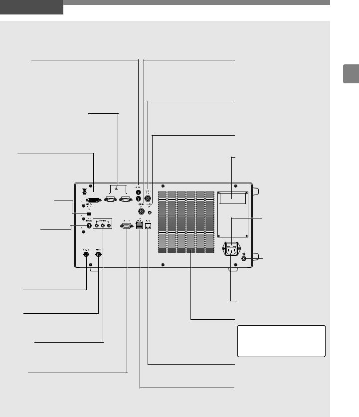
Rear Panel
Y/C OUT (Video/Printer Outputs)
These connectors (separated video outputs) are for outputting separate video signals (video signals separated into luminance signals and color signals) to send to a monitor or printer image processor.
RGB (Video/Printer Outputs)
These connectors are for outputting video signals (RGB color signals and synchronous signals) to send to a monitor or printer image processor.
DVI
This connector is for DVI or VGA.
SERIAL OUT1 DV
This connector is for outputting video signals
to send to DV equipment.
KEYBOARD
This connector is for connecting a keyboard.
You can connect either the supplied keyboard designed specifically for
use with the processor or a commercially available keyboard (US layout).
SA-P2
This connector is for connecting the SA-P2 water supply system.
FTSW
This connector is for connecting foot switches (OS-A61) for operating peripheral devices.
CONTROL
These connectors are for when you want to operate peripheral devices remotely.
RS232C
This connector (D-sub 9-pin connector) is for connecting an external output device. It is an RS232C compliant interface.
VIDEO IN |
|
(Composite Video Input) |
1 |
This connector (BNC connector) is |
for inputting composite video signals to display on the touch panel.
VIDEO OUT (Video Output)
This connector (BNC connector) is for outputting composite video signals to send to a monitor or image processor.
AUDIO IN (DV)
This connector is for inputting audio signals to send to DV equipment.
Rating Plate
This plate shows the processor rating specifications, acquired standards, etc.
Fuse Box
This fuse box contains two fuses.
Potential Equalization Terminal
This terminal is used
with a potential equalization busbar to equalize the potential of other equipment connected to the processor.
Power Input Socket
Connect the AC power cord.
Ventilation
Note
Install the processor in a location where the ventilation grid will not be blocked.
RJ45
This connector is exclusively for communication.
SERIAL OUT3/4
These connectors are for outputting the digital data of still images.
Names and Functions of Parts |
|
9 |
|
||
|
|
|

Water Bottle (OS-H4)
1
Water Bottle Nozzle 


Insert this into the processor.
Cap
Attach this so that no air leaks out.
Bottle
This bottle is for sterile water.
A/W (Air/Water Supply) and DRAIN (Drain) Switch Lever
Use this to switch between air/water supply and drain. Align the switch to the A/W position before use.
Bottle Tube
This is for sucking water from inside the bottle.
Air/Water Supply Tube
The inside of the tube is split into two for air and water supply.
Air/Water Supply Plug
Connect this to the air/ water supply connector of the scope.
10 Names and Functions of Parts

2Preparation
System Configuration 
The following shows examples of system configurations for using the processor.
K-series and i-series Endoscopes |
Display Devices |
2
|
|
LCD Monitor |
|
|
CRT Monitor |
|||
|
|
|
|
|
|
|
|
|
|
|
|
|
|
|
|
|
|
|
|
|
|
|
|
|
|
|
|
|
|
|
|
|
|
|
|
|
|
|
|
|
|
|
|
|
Recording Devices
EPK-i Processor
(This Processor)
Cart
VTR |
Magneto |
|
|
|
|
|
|
|
|
|
|
|
|
|
|
|
|
|
||
|
|
|
|
|
|
|
|
|
|
|
|
|
|
|
|
|
||||
|
|
|
|
|
|
|
|
|
|
|
|
|
|
|
|
|
||||
|
Optical Disk |
|
|
|
|
|
|
|
|
|
|
|
|
|
|
|
|
|
|
|
|
|
|
|
|
|
|
|
|
|
|
|
|
|
|
|
|
|
|
||
|
Recorder |
|
|
|
|
|
|
|
|
|
|
|
|
|
|
|
|
|
|
|
Isolation
Transformer
DVD Recorder |
Printer |
|
|
Input Devices |
|
USB Flash Memory |
Keyboard |
Foot Switches |
Preparation 11

Installation 
Installing the Processor in a Cart
Install the processor and peripheral devices while referring to the installation examples in dSystem Configuratione (P.11). Install the processor and peripheral devices in a cart. Make sure the cart is on a stable and level surface.
 CAUTION
zDo not install the processor in any of the following locations.
-Where the processor is likely to be exposed to water.
-Where flammable or explosive gas is present.
-In hot and humid locations.
2- Where the processor will be exposed to direct sunlight.
z Install the processor in a location where the ventilation grids will not be blocked.
zInstall the processor in a location where dust will not enter inside. Wipe off any dust on the processor. Excessive amounts of dust accumulating inside the unit may cause the processor to malfunction, emit smoke, or catch fire.
Connecting an Isolation Transformer
Connect the processor and peripheral devices to an isolation transformer. To reduce the possibility of an electric shock, be sure to supply power to the processor and peripheral devices from the SAT-1300 isolation transformer specified by PENTAX or another medical isolation transformer.

 Processor
AC Power Cord
Peripheral Device 


Isolation Transformer 

1Connect the power cord of the isolation transformer to a three-prong power outlet that meets the power rating indicated on the rating plate.
2Use the AC power cord to connect the power input socket on the rear panel of the processor to the isolation transformer.
j Make sure the processor is turned off beforehand.
3Connect the peripheral devices to the isolation transformer.
jMake sure the peripheral devices are turned off prior to installation.
jFor details on a peripheral device, refer to the instruction manual for the peripheral device.
 CAUTION
zDo not connect any electrical devices other than the processor and peripheral devices of the processor to the isolation transformer.
zMake sure the voltage, current, and power consumption of the processor and peripheral devices do not exceed the maximum ratings indicated on the isolation transformer.
z Be sure to securely connect the power cord of the isolation transformer to a three-prong power outlet.
12 Preparation
Connecting Peripheral Devices
Connect peripheral devices to the processor. Make sure the processor and peripheral devices are turned off beforehand.
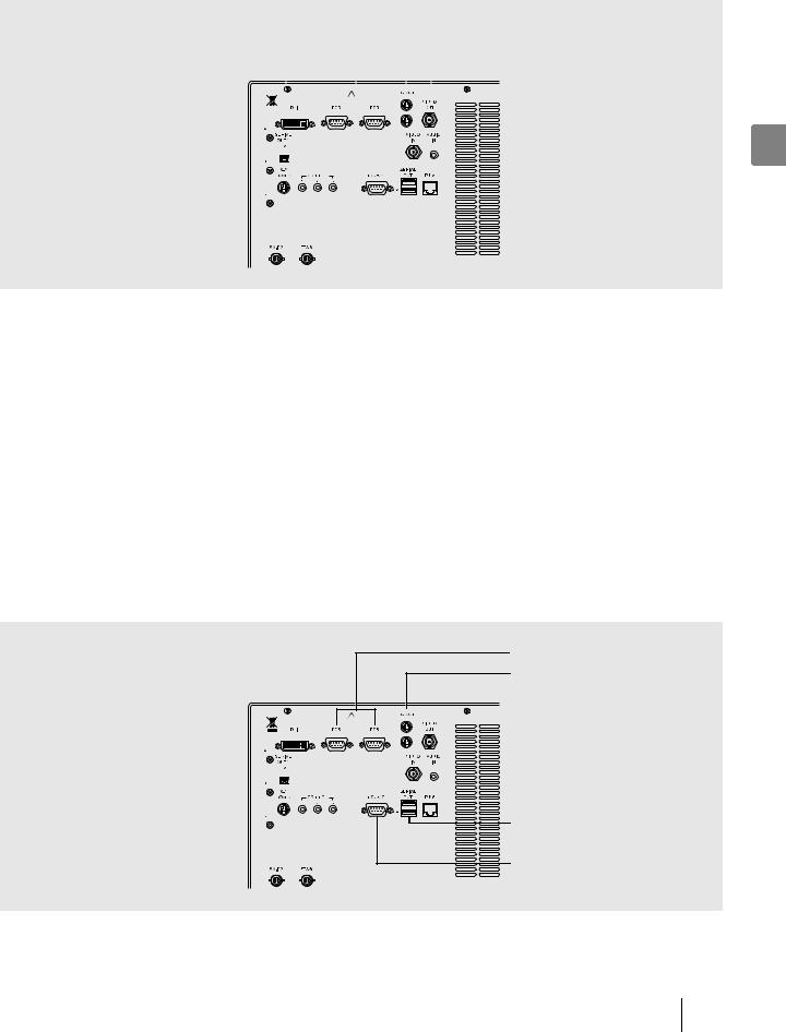
Connecting a Monitor
Connect a monitor to the processor. For details, refer to the instruction manual for the monitor.
DVI (DVI/VGA Monitors) |
|
|
|
|
|
|
|
|
|
|
|
|
RGB (Video/Printer Outputs) |
|
|
|
|
|
|
|
|
|
|
|
|
||
|
|
|
|
|
|
|
|
|
|
|
|
|
Y/C OUT (Video/Printer Outputs) |
|
|
|
|
|
|
|
|
|
|
|
|
|
VIDEO OUT (Video Output) |
|
|
|
|
|
|
|
|
|
|
|
|
|
|
|
|
|
|
|
|
|
|
|
|
|
|
|
|
|
|
|
|
|
|
|
|
|
|
|
|
|
|
|
|
|
|
|
|
|
|
|
|
|
|
|
|
|
|
|
|
|
|
|
|
|
|
|
|
|
|
|
|
|
|
|
|
|
|
|
|
|
|
|
|
|
|
|
|
|
|
|
|
|
|
|
|
|
|
2
Connecting a monitor with a DVI or VGA input
Use a DVI cable to connect the DVI connector to a DVI input of the monitor or a VGA cable to connect a VGA connector to a VGA input of the monitor.
I[Set up] J [Initial] J [Selection of the DVI or VGA] (P.28)
Connecting a monitor with a composite video input
Use a BNC video cable (OS-A17) to connect the VIDEO OUT (video output) connector to a composite video input of the monitor.
Connecting a monitor with an RGB video input (BNC)
Use an RGB cable (OS-A25) to connect an RGB (video/printer output) connector to an RGB video input (BNC) of the monitor.
Connecting a monitor with a 4-pin mini-DIN connector
Use a Y/C cable (OS-A24) to connect a Y/C OUT (video/printer output) connector to a 4-pin mini-DIN connector of the monitor.
Connecting a Printer
Connect a printer to the processor. For details, refer to the instruction manual for the printer.
Connecting a printer recommended by PENTAX enables you to match the colors of printouts to those of images on the monitor.
RGB (Video/Printer Outputs)
Y/C OUT (Video/Printer Outputs)
SERIAL OUT |
(USB Printer Output) |
RS232C
Using RGB output method
Use an RGB cable (OS-A25) to connect an RGB (video/printer output) connector to the connector of the printer.
Preparation 13
Using Y/C output method
Use a Y/C cable (OS-A24) to connect the Y/C OUT (video/printer output) connector to the connector of the printer.
Connecting a video printer (Sony UP-50 series) with an RS-232C input
Use an RS-232C cable to connect the RS232C connector to the connector of the printer.
I[Set up] J [Initial] J [RS232C Connection] (P.28) [Set up] J [Initial] J [Printer setting] (P.28)
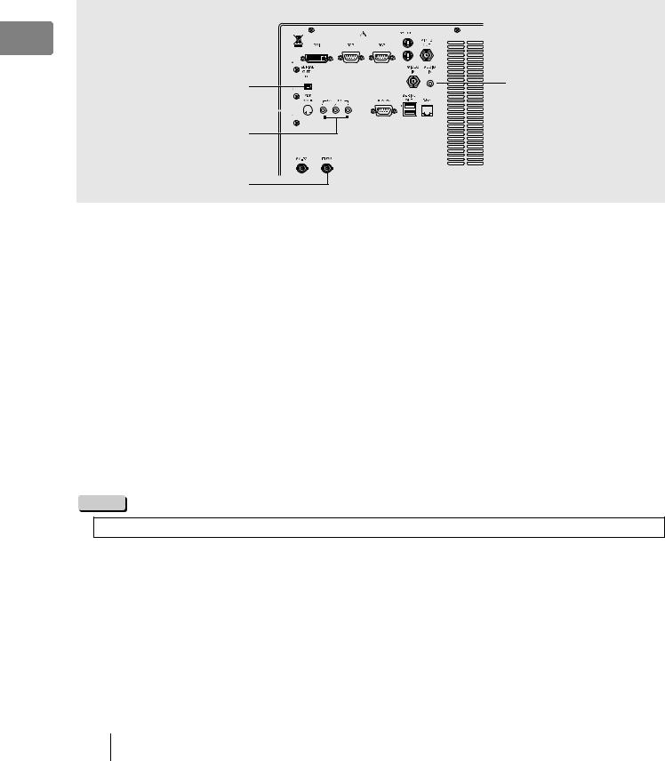
Connecting a Keyboard, Foot Switches, and Remote Controller
For details, refer to the corresponding instruction manuals.
2
SERIAL OUT1 DV |
AUDIO IN |
KEYBOARD 

CONTROL
FTSW
Connecting a keyboard
Connect a keyboard (OS-A70 or commercially available keyboard (US layout) to the KEYBOARD connector.
Connecting foot switches
Connect foot switches (OS-A61) to the FTSW connector.
Connecting a remote controller
When you want to use a peripheral device that includes support for remote (trigger) input, use a control cable (OS-A58) to connect the CONTROL connectors to the remote connectors of the peripheral device. For details on a peripheral device, refer to the instruction manual for the peripheral device.
Connecting to a video signal input of DV equipment
Connect the SERIAL OUT1 DV connector to a video signal input of DV equipment.
If you want to record video with audio, connect a microphone to the AUDIO IN connector. Use a microphone (with the following specifications) recommended by PENTAX.
Type: Stereo mini plug (three pins) Support for plug-in power
Audio characteristics: k40 to k50 dB
NOTE
When you want to use a commercially available keyboard, use a keyboard with a US layout.
14 Preparation
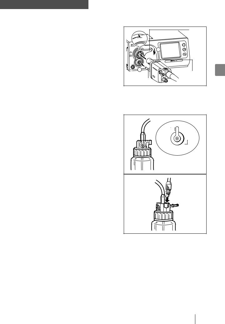
Connecting an Endoscope 
Connect a scope to the processor. Connect the water bottle and suction unit to the scope. For details on the scope, refer to the instruction manual for the scope.
1Align the scope locking lever of the processor to the OPEN position.
2Insert the electrical connector and light guide of the scope into the corresponding scope electrical connector 1 and light guide attachment of the processor and move the scope locking lever in the direction of 2 until it clicks into the LOCK position.
|
Scope |
|
Locking |
|
Lever |
|
2 |
1 |
2 |
|
Electrical |
Light Guide |
Connector |
|
3Pour sterile water into the water bottle until the bottle is about two thirds full and then securely tighten the cap.
4Insert the water bottle nozzle into the bottle connector of the processor.
5Align the A/W and DRAIN switch lever of the water bottle to the A/W (air/water supply) position.
A / W
DRAIN
j Insert the air/water supply plug into the holder.
Preparation 15

6Insert the air/water supply plug of the water bottle into the air/water supply connector of the scope.
Air/Water Supply Connector |
Air/Water Supply Plug |
27 Attach the suction tube of the suction unit to the suction nipple of the scope.
 CAUTION
z Be sure to use sterile water for the water bottle, and replace the water everyday.
z Be careful not to turn the water bottle upside down, or squeeze it. Doing so may result in water flowing out of the bottle. z Make sure the scope is inserted slowly and correctly.
z Do not hold the scope locking lever when you move the processor.
16 Preparation

3Pre-use Inspections
Be sure to perform the following inspections before you use the processor. If you discover any abnormality, stop using the processor immediately and contact our service personnel.
Check the following before you begin the inspections.
jThe processor is turned off.
jThe processor is installed in a stable and level location.
jThe water bottle is prepared appropriately and connected properly.
jThe scope is connected properly.
jThe keyboard is connected properly.
 WARNING
Be sure to supply power to the processor and peripheral devices from the SAT-1300 isolation transformer specified by PENTAX or another medical isolation transformer.
3
Power and Lamp Inspection
1Turn on the monitor and peripheral devices.
2Press R to turn on the processor and make sure the R LED lights green.
jThe touch panel lights after approximately 1 minute.
jMake sure two or three bars of the LIFE indicator (lamp life indicator) on the touch panel are lit green.
jIf pressing R does not turn on the processor, check the fuses. IdReplacing the Fusese (P.47)
 CAUTION
The lamp life is 400 hours. Check the LIFE indicator (lamp life indicator) on the touch panel before you use the processor. Replace the lamp cartridge if one bar of the LIFE indicator lights red and the [Please replace the lamp] message appears on the monitor.
IdReplacing the Lamp Cartridgee (P.45)
3Press J.
4Make sure the processor main lamp and J LED light and the distal end of the scope emits light.
 WARNING
Do not look directly at light emitted from the distal end of the scope.
NOTE
If lamp fails to ignite, do not attempt to perform an endoscopic examination, contact your PENTAX service facility.
Pre-use Inspections |
|
17 |
|
||
|
|
|
 Loading...