


Cat. No. I527-E1-04
USER’S MANUAL
SYSDRIVE 3G3MV
Multi-function Compact Inverter

Thank you for choosing this SYSDRIVE 3G3MV-series product. Proper use and handling of the product will ensure proper product performance, will lengthen product life, and may prevent possible accidents.
Please read this manual thoroughly and handle and operate the product with care.
1.To ensure safe and proper use of the OMRON Inverters, please read this USER’S MANUAL (Cat. No. I527-E1) to gain sufficient knowledge of the devices, safety information, and precautions before actual use.
2.The products are illustrated without covers and shieldings for closer look in this USER’S MANUAL. For actual use of the products, make sure to use the covers and shieldings as specified.
3.This USER’S MANUAL and other related user’s manuals are to be delivered to the actual end users of the products.
4.Please keep this manual close at hand for future reference.
5.If the product has been left unused for a long time, please inquire at our sales representative.
NOTICE
1.This manual describes the functions of the product and relations with other products. You should assume that anything not described in this manual is not possible.
2.Although care has been given in documenting the product, please contact your OMRON representative if you have any suggestions on improving this manual.
3.The product contains potentially dangerous parts under the cover. Do not attempt to open the cover under any circumstances. Doing so may result in injury or death and may damage the product. Never attempt to repair or disassemble the product.
4.We recommend that you add the following precautions to any instruction manuals you prepare for the system into which the product is being installed.
S Precautions on the dangers of high-voltage equipment.
S Precautions on touching the terminals of the product even after power has been turned off. (These terminals are live even with the power turned off.)
5.Specifications and functions may be changed without notice in order to improve product performance.
Items to Check Before Unpacking
Check the following items before removing the product from the package:
SHas the correct product been delivered (i.e., the correct model number and specifications)?
SHas the product been damaged in shipping?
SAre any screws or bolts loose?
USER’S MANUAL
SYSDRIVE 3G3MVSERIES
Multi-function Compact Inverter
Notice:
OMRON products are manufactured for use according to proper procedures by a qualified operator and only for the purposes described in this manual.
The following conventions are used to indicate and classify precautions in this manual. Always heed the information provided with them. Failure to heed precautions can result in injury to people or damage to property.
! DANGER Indicates an imminently hazardous situation which, if not avoided, will result in death or serious injury. Additionally, there may be severe property damage.
! WARNING Indicates a potentially hazardous situation which, if not avoided, could result in death or serious injury. Additionally, there may be severe property damage.
! Caution Indicates a potentially hazardous situation which, if not avoided, may result in minor or moderate injury, or property damage.
OMRON Product References
All OMRON products are capitalized in this manual. The word “Unit” is also capitalized when it refers to an OMRON product, regardless of whether or not it appears in the proper name of the product.
The abbreviation “Ch,” which appears in some displays and on some OMRON products, often means “word” and is abbreviated “Wd” in documentation in this sense.
The abbreviation “PLC” means Programmable Controller.
Visual Aids
The following headings appear in the left column of the manual to help you locate different types of information.
Note Indicates information of particular interest for efficient and convenient operation of the product.
OMRON, 1999
All rights reserved. No part of this publication may be reproduced, stored in a retrieval system, or transmitted, in any form, or by any means, mechanical, electronic, photocopying, recording, or otherwise, without the prior written permission of OMRON.
No patent liability is assumed with respect to the use of the information contained herein. Moreover, because OMRON is constantly striving to improve its high-quality products, the information contained in this manual is subject to change without notice. Every precaution has been taken in the preparation of this manual. Nevertheless, OMRON assumes no responsibility for errors or omissions. Neither is any liability assumed for damages resulting from the use of the information contained in this publication.

General Precautions
Observe the following precautions when using the SYSDRIVE Inverters and peripheral devices.
This manual may include illustrations of the product with protective covers removed in order to describe the components of the product in detail. Make sure that these protective covers are on the product before use.
Consult your OMRON representative when using the product after a long period of storage.
!WARNING Do not touch the inside of the Inverter. Doing so may result in electrical shock.
!WARNING Operation, maintenance, or inspection must be performed after turning OFF the
power supply, confirming that the CHARGE indicator (or status indicators) are OFF, and after waiting for the time specified on the front cover. Not doing so may result in electrical shock.
! WARNING Do not damage, pull on, apply stress to, place heavy objects on, or pinch the cables. Doing so may result in electrical shock.
! WARNING Do not touch the rotating parts of the motor under operation. Doing so may result in injury.
!WARNING Do not modify the product. Doing so may result in injury or damage to the product.
!Caution Do not store, install, or operate the product in the following places. Doing so may
result in electrical shock, fire or damage to the product.
SLocations subject to direct sunlight.
SLocations subject to temperatures or humidity outside the range specified in the specifications.
SLocations subject to condensation as the result of severe changes in temperature.
SLocations subject to corrosive or flammable gases.
SLocations subject to exposure to combustibles.
SLocations subject to dust (especially iron dust) or salts.
SLocations subject to exposure to water, oil, or chemicals.
SLocations subject to shock or vibration.
!Caution Do not touch the Inverter radiator, regenerative resistor, or Servomotor while the
power is being supplied or soon after the power is turned OFF. Doing so may result in a skin burn due to the hot surface.
! Caution Do not conduct a dielectric strength test on any part of the Inverter. Doing so may result in damage to the product or malfunction.
! Caution Take appropriate and sufficient countermeasures when installing systems in the following locations. Not doing so may result in equipment damage.
SLocations subject to static electricity or other forms of noise.
SLocations subject to strong electromagnetic fields and magnetic fields.
SLocations subject to possible exposure to radioactivity.
SLocations close to power supplies.

Transportation Precautions
! Caution Do not hold by front cover or panel , instead, hold by the radiation fin (heat sink) while transporting the product. Doing so may result in injury.
! Caution Do not pull on the cables. Doing so may result in damage to the product or malfunction.
! Caution Use the eye-bolts only for transporting the Inverter. Using them for transporting the machinery may result in injury or malfunction.
Installation Precautions
! WARNING Provide an appropriate stopping device on the machine side to secure safety. (A holding brake is not a stopping device for securing safety.) Not doing so may result in injury.
! WARNING Provide an external emergency stopping device that allows an instantaneous stop of operation and power interruption. Not doing so may result in injury.
! Caution Be sure to install the product in the correct direction and provide specified clearances between the Inverter and control panel or with other devices. Not doing so may result in fire or malfunction.
! Caution Do not allow foreign objects to enter inside the product. Doing so may result in fire or malfunction.
! Caution Do not apply any strong impact. Doing so may result in damage to the product or malfunction.
Wiring Precautions
! WARNING Wiring must be performed only after confirming that the power supply has been turned OFF. Not doing so may result in electrical shock.
! WARNING Wiring must be performed by authorized personnel. Not doing so may result in electrical shock or fire.
! WARNING Be sure to confirm operation only after wiring the emergency stop circuit. Not doing so may result in injury.
! WARNING Always connect the ground terminals to a ground of 100 Ω or less for the 200-V AC class, or 10 Ω or less for the 400-V AC class. Not connecting to a proper ground may result in electrical shock.

! Caution Install external breakers and take other safety measures against short-circuiting in external wiring. Not doing so may result in fire.
! Caution Confirm that the rated input voltage of the Inverter is the same as the AC power supply voltage. An incorrect power supply may result in fire, injury, or malfunction.
! Caution Connect the Braking Resistor and Braking Resistor Unit as specified in the manual. Not doing so may result in fire.
! Caution Be sure to wire correctly and securely. Not doing so may result in injury or damage to the product.
! Caution Be sure to firmly tighten the screws on the terminal block. Not doing so may result in fire, injury, or damage to the product.
! Caution Do not connect an AC power to the U, V, or W output. Doing so may result in damage to the product or malfunction.
! Caution The motor may start operation if input terminal S2 is turned ON with the default parameter settings. Wire terminals with NC contacts (e.g., 3-wire sequences) only after setting the multi-function input parameters.
Operation and Adjustment Precautions
! WARNING Turn ON the input power supply only after mounting the front cover, terminal covers, bottom cover, Operator, and optional items. Not doing so may result in electrical shock.
! WARNING Do not remove the front cover, terminal covers, bottom cover, Operator, or optional items while the power is being supplied. Not doing so may result in electrical shock or damage to the product.
! WARNING Do not operate the Operator or switches with wet hands. Doing so may result in electrical shock.
!WARNING Do not touch the inside of the Inverter. Doing so may result in electrical shock.
!WARNING Do not come close to the machine when using the error retry function because the
machine may abruptly start when stopped by an alarm. Doing so may result in injury.
! WARNING Do not come close to the machine immediately after resetting momentary power interruption to avoid an unexpected restart (if operation is set to be continued in the processing selection function after momentary power interruption is reset). Doing so may result in injury.

! WARNING Provide a separate emergency stop switch because the STOP Key on the Operator is valid only when function settings are performed. Not doing so may result in injury.
! WARNING Be sure confirm that the RUN signal is turned OFF before turning ON the power supply, resetting the alarm, or switching the LOCAL/REMOTE selector. Doing so while the RUN signal is turned ON may result in injury.
! Caution Be sure to confirm permissible ranges of motors and machines before operation because the Inverter speed can be easily changed from low to high. Not doing so may result in damage to the product.
!Caution Provide a separate holding brake when necessary. Not doing so may result in injury.
!Caution Do not perform a signal check during operation. Doing so may result in injury or dam-
age to the product.
! Caution Do not carelessly change settings. Doing so may result in injury or damage to the product.
Maintenance and Inspection Precautions
!WARNING Do not touch the Inverter terminals while the power is being supplied.
!WARNING Maintenance or inspection must be performed only after turning OFF the power
supply, confirming that the CHARGE indicator (or status indicators) is turned OFF, and after waiting for the time specified on the front cover. Not doing so may result in electrical shock.
! WARNING Maintenance, inspection, or parts replacement must be performed by authorized personnel. Not doing so may result in electrical shock or injury.
! WARNING Do not attempt to take the Unit apart or repair. Doing either of these may result in electrical shock or injury.
! Caution Carefully handle the Inverter because it uses semiconductor elements. Careless handling may result in malfunction.
! Caution Do not change wiring, disconnect connectors, the Operator, or optional items, or replace fans while power is being supplied. Doing so may result in injury, damage to the product, or malfunction.
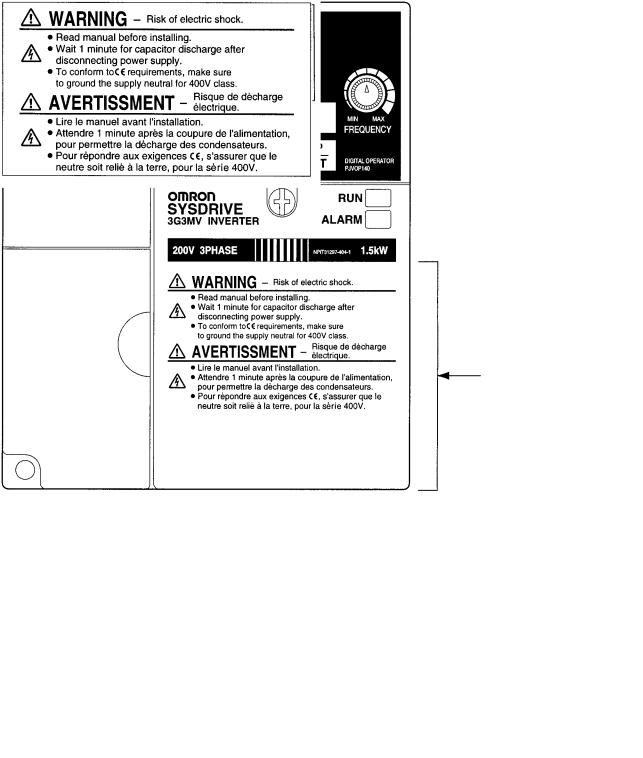
Warning Labels
Warning labels are pasted on the product as shown in the following illustration. Be sure to follow the instructions given there.
H Warning Labels
Warning label
H Contents of Warning
Checking Before Unpacking
H Checking the Product
On delivery, always check that the delivered product is the SYSDRIVE 3G3MV Inverter that you ordered.
Should you find any problems with the product, immediately contact your nearest local sales representative.
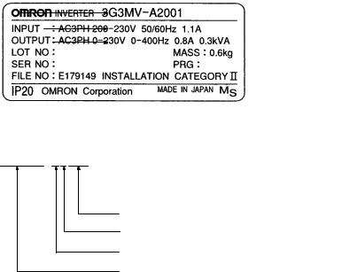
D Checking the Nameplate
Inverter model
Input specifications
Output specifications
D Checking the Model
3G3MV-A4007
Maximum applicable motor capacity
Voltage class
Installation type
Series name: 3G3MV Series
Maximum Applicable Motor Capacity
001 |
0.1 |
(0.1) kW |
|
|
|
002 |
0.25/0.37 (0.2) kW |
|
|
|
|
004 |
0.55 (0.4) kW |
|
|
|
|
007 |
1.1 |
(0.75) kW |
|
|
|
015 |
1.5 |
(1.5) kW |
|
|
|
022 |
2.2 |
(2.2) kW |
|
|
|
037 |
3.7 |
(3.7) kW |
|
|
|
055 |
5.5 |
(5.5) kW |
|
|
|
075 |
7.5 |
(7.5) kW |
Note The figures in parentheses indicate capacities for motors used in Japan.
Voltage Class
2 |
Three-phase 200-V AC input (200-V class) |
|
|
B |
Single-phase 200-V AC input (200-V class) |
|
|
4 |
Three-phase 400-V AC input (400-V class) |
Installation Type
A |
Panel-mounting (IP10 min.) or closed wall-mounting models |
|
|
C |
Closed wall-mounting models |
|
(NEMA1 type for North America) |
Note A-type models with 5.5-KW and 7.5-KW capacity also have NEMA1 enclosure ratings.
D Checking for Damage
Check the overall appearance and check for damage or scratches resulting from transportation.
H Checking the Accessories
Note that this manual is the only accessory provided with the 3G3MV. Set screws and other necessary parts must be provided by the user.

Read and Understand this Manual
Please read and understand this manual before using the product. Please consult your OMRON representative if you have any questions or comments.
Warranty and Limitations of Liability
WARRANTY
OMRON’s exclusive warranty is that the products are free from defects in materials and workmanship for a period of one year (or other period if specified) from date of sale by OMRON.
OMRON MAKES NO WARRANTY OR REPRESENTATION, EXPRESS OR IMPLIED, REGARDING NON-INFRINGEMENT, MERCHANTABILITY, OR FITNESS FOR PARTICULAR PURPOSE OF THE PRODUCTS. ANY BUYER OR USER ACKNOWLEDGES THAT THE BUYER OR USER ALONE HAS DETERMINED THAT THE PRODUCTS WILL SUITABLY MEET THE REQUIREMENTS OF THEIR INTENDED USE. OMRON DISCLAIMS ALL OTHER WARRANTIES, EXPRESS OR IMPLIED.
LIMITATIONS OF LIABILITY
OMRON SHALL NOT BE RESPONSIBLE FOR SPECIAL, INDIRECT, OR CONSEQUENTIAL DAMAGES, LOSS OF PROFITS OR COMMERCIAL LOSS IN ANY WAY CONNECTED WITH THE PRODUCTS, WHETHER SUCH CLAIM IS BASED ON CONTRACT, WARRANTY, NEGLIGENCE, OR STRICT LIABILITY.
In no event shall the responsibility of OMRON for any act exceed the individual price of the product on which liability is asserted.
IN NO EVENT SHALL OMRON BE RESPONSIBLE FOR WARRANTY, REPAIR, OR OTHER CLAIMS REGARDING THE PRODUCTS UNLESS OMRON’S ANALYSIS CONFIRMS THAT THE PRODUCTS WERE PROPERLY HANDLED, STORED, INSTALLED, AND MAINTAINED AND NOT SUBJECT TO CONTAMINATION, ABUSE, MISUSE, OR INAPPROPRIATE MODIFICATION OR REPAIR.

Application Considerations
SUITABILITY FOR USE
OMRON shall not be responsible for conformity with any standards, codes, or regulations that apply to the combination of products in the customer’s application or use of the products.
At the customer’s request, OMRON will provide applicable third party certification documents identifying ratings and limitations of use that apply to the products. This information by itself is not sufficient for a complete determination of the suitability of the products in combination with the end product, machine, system, or other application or use.
The following are some examples of applications for which particular attention must be given. This is not intended to be an exhaustive list of all possible uses of the products, nor is it intended to imply that the uses listed may be suitable for the products:
•Outdoor use, uses involving potential chemical contamination or electrical interference, or conditions or uses not described in this manual.
•Nuclear energy control systems, combustion systems, railroad systems, aviation systems, medical equipment, amusement machines, vehicles, safety equipment, and installations subject to separate industry or government regulations.
•Systems, machines, and equipment that could present a risk to life or property.
Please know and observe all prohibitions of use applicable to the products.
NEVER USE THE PRODUCTS FOR AN APPLICATION INVOLVING SERIOUS RISK TO LIFE OR PROPERTY WITHOUT ENSURING THAT THE SYSTEM AS A WHOLE HAS BEEN DESIGNED TO ADDRESS THE RISKS, AND THAT THE OMRON PRODUCTS ARE PROPERLY RATED AND INSTALLED FOR THE INTENDED USE WITHIN THE OVERALL EQUIPMENT OR SYSTEM.
PROGRAMMABLE PRODUCTS
OMRON shall not be responsible for the user’s programming of a programmable product, or any consequence thereof.

Disclaimers
CHANGE IN SPECIFICATIONS
Product specifications and accessories may be changed at any time based on improvements and other reasons.
It is our practice to change model numbers when published ratings or features are changed, or when significant construction changes are made. However, some specifications of the products may be changed without any notice. When in doubt, special model numbers may be assigned to fix or establish key specifications for your application on your request. Please consult with your OMRON representative at any time to confirm actual specifications of purchased products.
DIMENSIONS AND WEIGHTS
Dimensions and weights are nominal and are not to be used for manufacturing purposes, even when tolerances are shown.
PERFORMANCE DATA
Performance data given in this manual is provided as a guide for the user in determining suitability and does not constitute a warranty. It may represent the result of OMRON’s test conditions, and the users must correlate it to actual application requirements. Actual performance is subject to the OMRON Warranty and Limitations of Liability.
ERRORS AND OMISSIONS
The information in this manual has been carefully checked and is believed to be accurate; however, no responsibility is assumed for clerical, typographical, or proofreading errors, or omissions.
About this Manual
This manual is divided into the chapters described in the following table. Information is organized by application area to enable you to use the manual more efficiently.
Chapter |
Contents |
|
|
Chapter 1 Overview |
Describes features and nomenclature. |
|
|
Chapter 2 Design |
Provides dimensions, installation methods, wiring methods, peripheral |
|
device design information, and peripheral device selection information. |
|
|
Chapter 3 Preparing for Operation |
Describes nomenclature and Digital Operator procedures for operating |
and Monitoring |
and monitoring Inverters. Data copying and other functions are |
|
described. |
|
|
Chapter 4 Test Run |
Describes the method for controlling a motor through the frequency |
|
adjuster on the front of the Inverter. This can be used for trial |
|
operation of the system. |
|
|
Chapter 5 Basic Operation |
Describes basic Inverter control functions for users not familiar with |
|
Inverters. The functions that must be understood to drive a motor with |
|
an Inverter are described. |
|
|
Chapter 6 Advanced Operation |
Describes all of the functions provided by the Inverter. These functions |
|
will enable more advanced applications, and includes functions that |
|
will improve motor control through the Inverter, such as |
|
responsiveness (torque characteristics), increasing speed accuracy, |
|
PID control, overtorque detection, and other functions. |
|
|
Chapter 7 Communications |
Describes the general-purpose RS-422/RS-485 communications |
|
functions provided by the Inverter, including connection methods and |
|
sample programming for SYSMAC Programmable Controllers. |
|
|
Chapter 8 Maintenance Operations |
Provides maintenance, inspection, and troubleshooting information. |
|
|
Chapter 9 Specifications |
Provides Inverter specifications, as well as the specifications and |
|
dimensions of peripheral devices. |
Chapter 10 List of Parameters |
Lists basic information on Inverter parameters as a reference for users |
|
already familiar with Inverter operation. Parameters are listed in order |
|
with the page numbers of further information for easy reference. |
|
|
Chapter 11 Using the Inverter for a |
Describes information on using the Inverter for a motor. |
Motor |
|

Table of Contents
Chapter 1. Overview . . . . . . . . . . . . . . . . . . . . . . . . . . . . . . . . . . . . . . . . 1-1
1-1 Functions . . . . . . . . . . . . . . . . . . . . . . . . . . . . . . . . . . . . . . . . . . . . . . . . . . . . . . . . . . . . . . . . . . 1-2
1-2 Nomenclature . . . . . . . . . . . . . . . . . . . . . . . . . . . . . . . . . . . . . . . . . . . . . . . . . . . . . . . . . . . . . . . 1-5
1-3 New Features . . . . . . . . . . . . . . . . . . . . . . . . . . . . . . . . . . . . . . . . . . . . . . . . . . . . . . . . . . . . . . . 1-8
Chapter 2. Design . . . . . . . . . . . . . . . . . . . . . . . . . . . . . . . . . . . . . . . . . . 2-1
2-1 Installation . . . . . . . . . . . . . . . . . . . . . . . . . . . . . . . . . . . . . . . . . . . . . . . . . . . . . . . . . . . . . . . . . 2-2 2-1-1 Dimensions . . . . . . . . . . . . . . . . . . . . . . . . . . . . . . . . . . . . . . . . . . . . . . . . . . . . . . . . . . 2-2 2-1-2 Installation Conditions . . . . . . . . . . . . . . . . . . . . . . . . . . . . . . . . . . . . . . . . . . . . . . . . . 2-6 2-1-3 Removing and Mounting the Covers . . . . . . . . . . . . . . . . . . . . . . . . . . . . . . . . . . . . . . 2-8 2-2 Wiring . . . . . . . . . . . . . . . . . . . . . . . . . . . . . . . . . . . . . . . . . . . . . . . . . . . . . . . . . . . . . . . . . . . . 2-11 2-2-1 Terminal Block . . . . . . . . . . . . . . . . . . . . . . . . . . . . . . . . . . . . . . . . . . . . . . . . . . . . . . . 2-12 2-2-2 Standard Connections . . . . . . . . . . . . . . . . . . . . . . . . . . . . . . . . . . . . . . . . . . . . . . . . . . 2-20 2-2-3 Wiring around the Main Circuit . . . . . . . . . . . . . . . . . . . . . . . . . . . . . . . . . . . . . . . . . . 2-21 2-2-4 Wiring Control Circuit Terminals . . . . . . . . . . . . . . . . . . . . . . . . . . . . . . . . . . . . . . . . . 2-34 2-2-5 Conforming to EC Directives . . . . . . . . . . . . . . . . . . . . . . . . . . . . . . . . . . . . . . . . . . . . 2-36
Chapter 3. Preparing for Operation and Monitoring . . . . . . . . . . . . . 3-1
3-1 |
Nomenclature . . . . . . . . . . . . . . . . . . . . . . . . . . . . . . . . . . . . . . . . . . . . . . . . . . . . . . . . . . . . . . . |
3-2 |
|
|
3-1-1 Names of Parts and their Functions . . . . . . . . . . . . . . . . . . . . . . . . . . . . . . . . . . . . . . . |
3-2 |
|
|
3-1-2 |
Outline of Operation . . . . . . . . . . . . . . . . . . . . . . . . . . . . . . . . . . . . . . . . . . . . . . . . . . . |
3-4 |
3-2 |
Parameter Copy and Verify Function . . . . . . . . . . . . . . . . . . . . . . . . . . . . . . . . . . . . . . . . . . . . |
3-10 |
|
|
3-2-1 Parameter for Copying and Verifying Set Values . . . . . . . . . . . . . . . . . . . . . . . . . . . . . |
3-10 |
|
|
3-2-2 |
Parameter Copying Procedure . . . . . . . . . . . . . . . . . . . . . . . . . . . . . . . . . . . . . . . . . . . |
3-11 |
|
3-2-3 |
Parameter Read-prohibit Selection (Prohibiting Data Written to the EEPROM of |
|
|
|
the Digital Operator) . . . . . . . . . . . . . . . . . . . . . . . . . . . . . . . . . . . . . . . . . . . . . . . . . . . |
3-17 |
|
3-2-4 |
Parameter Copy or Verify Errors . . . . . . . . . . . . . . . . . . . . . . . . . . . . . . . . . . . . . . . . . |
3-18 |
|
|
||
Chapter 4. Test Run . . . . . . . . . . . . . . . . . . . . . . . . . . . . . . . . . . . . . . . . |
4-1 |
||
|
|
|
|
4-1 Procedure for Test Run . . . . . . . . . . . . . . . . . . . . . . . . . . . . . . . . . . . . . . . . . . . . . . . . . . . . . . . 4-3 4-2 Operation Example . . . . . . . . . . . . . . . . . . . . . . . . . . . . . . . . . . . . . . . . . . . . . . . . . . . . . . . . . . 4-5
Chapter 5. Basic Operation . . . . . . . . . . . . . . . . . . . . . . . . . . . . . . . . . . 5-1
5-1 Initial Settings . . . . . . . . . . . . . . . . . . . . . . . . . . . . . . . . . . . . . . . . . . . . . . . . . . . . . . . . . . . . . . 5-2 5-1-1 Setting the Parameter Write-prohibit Selection/Parameter Initialization (n001) . . . . 5-2 5-1-2 Setting the Control Mode (n002) . . . . . . . . . . . . . . . . . . . . . . . . . . . . . . . . . . . . . . . . . 5-3 5-2 Operation in Vector Control . . . . . . . . . . . . . . . . . . . . . . . . . . . . . . . . . . . . . . . . . . . . . . . . . . . 5-5
5-3 Operation in V/f Control . . . . . . . . . . . . . . . . . . . . . . . . . . . . . . . . . . . . . . . . . . . . . . . . . . . . . . 5-7 5-3-1 Setting the Rated Motor Current (n036) . . . . . . . . . . . . . . . . . . . . . . . . . . . . . . . . . . . . 5-7 5-3-2 Setting the V/f Patterns (n011 to n017) . . . . . . . . . . . . . . . . . . . . . . . . . . . . . . . . . . . . 5-7 5-4 Setting the Local/Remote Mode . . . . . . . . . . . . . . . . . . . . . . . . . . . . . . . . . . . . . . . . . . . . . . . . 5-9
5-5 Selecting the Operation Command . . . . . . . . . . . . . . . . . . . . . . . . . . . . . . . . . . . . . . . . . . . . . . 5-10 5-6 Setting the Frequency Reference . . . . . . . . . . . . . . . . . . . . . . . . . . . . . . . . . . . . . . . . . . . . . . . . 5-11 5-6-1 Selecting the Frequency Reference . . . . . . . . . . . . . . . . . . . . . . . . . . . . . . . . . . . . . . . 5-11 5-6-2 Upper and Lower Frequency Reference Limits . . . . . . . . . . . . . . . . . . . . . . . . . . . . . . 5-12 5-6-3 Frequency Referencing by Analog Input . . . . . . . . . . . . . . . . . . . . . . . . . . . . . . . . . . . 5-13 5-6-4 Setting Frequency References through Key Sequences . . . . . . . . . . . . . . . . . . . . . . . . 5-18 5-6-5 Setting Frequency References by Pulse Train Input . . . . . . . . . . . . . . . . . . . . . . . . . . 5-23

Table of Contents
5-7 Setting the Acceleration/Deceleration Time . . . . . . . . . . . . . . . . . . . . . . . . . . . . . . . . . . . . . . . 5-25 5-8 Selecting the Reverse Rotation-prohibit . . . . . . . . . . . . . . . . . . . . . . . . . . . . . . . . . . . . . . . . . . 5-28 5-9 Selecting the Stopping Method . . . . . . . . . . . . . . . . . . . . . . . . . . . . . . . . . . . . . . . . . . . . . . . . . 5-29 5-10 Multi-function I/O . . . . . . . . . . . . . . . . . . . . . . . . . . . . . . . . . . . . . . . . . . . . . . . . . . . . . . . . . . . 5-30 5-10-1 Multi-function Input . . . . . . . . . . . . . . . . . . . . . . . . . . . . . . . . . . . . . . . . . . . . . . . . . . . 5-30 5-10-2 Multi-function Output . . . . . . . . . . . . . . . . . . . . . . . . . . . . . . . . . . . . . . . . . . . . . . . . . . 5-36 5-11 Multi-function Analog Output and Pulse Monitor Output . . . . . . . . . . . . . . . . . . . . . . . . . . . . 5-38 5-11-1 Setting the Multi-function Analog Output (n065 through n067) . . . . . . . . . . . . . . . . . 5-38 5-11-2 Setting the Pulse Monitor Output (n065 and n150) . . . . . . . . . . . . . . . . . . . . . . . . . . . 5-39
. . . . . . . . . . . . . . . . . . . . . . . . . . . . . .Chapter 6. Advanced Operation |
6-1 |
||
|
|
||
6-1 Precise Vector Control Settings and Adjustments . . . . . . . . . . . . . . . . . . . . . . . . . . . . . . . . . . . |
6-2 |
||
|
6-1-1 |
Precise Vector Control Settings . . . . . . . . . . . . . . . . . . . . . . . . . . . . . . . . . . . . . . . . . . |
6-2 |
|
6-1-2 |
Adjusting Output Torque in Vector Control . . . . . . . . . . . . . . . . . . . . . . . . . . . . . . . . . |
6-3 |
6-2 |
Energy-saving Control . . . . . . . . . . . . . . . . . . . . . . . . . . . . . . . . . . . . . . . . . . . . . . . . . . . . . . . . |
6-5 |
|
|
6-2-1 |
Energy-saving Control Operation . . . . . . . . . . . . . . . . . . . . . . . . . . . . . . . . . . . . . . . . . |
6-5 |
|
6-2-2 |
Performing Energy-saving Settings . . . . . . . . . . . . . . . . . . . . . . . . . . . . . . . . . . . . . . . |
6-6 |
6-3 |
PID Control . . . . . . . . . . . . . . . . . . . . . . . . . . . . . . . . . . . . . . . . . . . . . . . . . . . . . . . . . . . . . . . . |
6-11 |
|
|
6-3-1 |
PID Control Applications . . . . . . . . . . . . . . . . . . . . . . . . . . . . . . . . . . . . . . . . . . . . . . . |
6-11 |
|
6-3-2 |
PID Control Operation . . . . . . . . . . . . . . . . . . . . . . . . . . . . . . . . . . . . . . . . . . . . . . . . . |
6-12 |
|
6-3-3 Types of PID Control . . . . . . . . . . . . . . . . . . . . . . . . . . . . . . . . . . . . . . . . . . . . . . . . . . |
6-12 |
|
|
6-3-4 Block Diagram of PID Control . . . . . . . . . . . . . . . . . . . . . . . . . . . . . . . . . . . . . . . . . . . |
6-14 |
|
|
6-3-5 Input Selection of PID Control Target Value and Detection Value . . . . . . . . . . . . . . . |
6-15 |
|
|
6-3-6 |
PID Control Settings . . . . . . . . . . . . . . . . . . . . . . . . . . . . . . . . . . . . . . . . . . . . . . . . . . . |
6-16 |
|
6-3-7 |
PID Adjustments . . . . . . . . . . . . . . . . . . . . . . . . . . . . . . . . . . . . . . . . . . . . . . . . . . . . . . |
6-19 |
|
6-3-8 |
PID Fine Tuning . . . . . . . . . . . . . . . . . . . . . . . . . . . . . . . . . . . . . . . . . . . . . . . . . . . . . . |
6-21 |
6-4 Setting the Carrier Frequency . . . . . . . . . . . . . . . . . . . . . . . . . . . . . . . . . . . . . . . . . . . . . . . . . . |
6-23 |
||
6-5 DC Injection Braking Function . . . . . . . . . . . . . . . . . . . . . . . . . . . . . . . . . . . . . . . . . . . . . . . . . |
6-26 |
||
6-6 |
Stall Prevention Function . . . . . . . . . . . . . . . . . . . . . . . . . . . . . . . . . . . . . . . . . . . . . . . . . . . . . |
6-27 |
|
6-7 |
Overtorque/Undertorque Detection Function . . . . . . . . . . . . . . . . . . . . . . . . . . . . . . . . . . . . . . |
6-31 |
|
6-8 |
Torque Compensation Function . . . . . . . . . . . . . . . . . . . . . . . . . . . . . . . . . . . . . . . . . . . . . . . . . |
6-35 |
|
6-9 |
Slip Compensation Function . . . . . . . . . . . . . . . . . . . . . . . . . . . . . . . . . . . . . . . . . . . . . . . . . . . |
6-37 |
|
6-10 Other Functions . . . . . . . . . . . . . . . . . . . . . . . . . . . . . . . . . . . . . . . . . . . . . . . . . . . . . . . . . . . . . |
6-39 |
||
|
6-10-1 Digital Operator Disconnection Error Detection . . . . . . . . . . . . . . . . . . . . . . . . . . . . . |
6-39 |
|
|
6-10-2 Motor Protection Functions (n037 and n038) . . . . . . . . . . . . . . . . . . . . . . . . . . . . . . . . |
6-39 |
|
|
6-10-3 Cooling Fan Operation Function (n039) . . . . . . . . . . . . . . . . . . . . . . . . . . . . . . . . . . . |
6-40 |
|
|
6-10-4 Momentary Power Interruption Compensation (n081) . . . . . . . . . . . . . . . . . . . . . . . . |
6-40 |
|
|
6-10-5 Fault Retry (n082) . . . . . . . . . . . . . . . . . . . . . . . . . . . . . . . . . . . . . . . . . . . . . . . . . . . . . |
6-41 |
|
|
6-10-6 Frequency Jump Function (n083 to n086) . . . . . . . . . . . . . . . . . . . . . . . . . . . . . . . . . . |
6-42 |
|
|
6-10-7 Accumulated Operating Time (n087, n088) . . . . . . . . . . . . . . . . . . . . . . . . . . . . . . . . . |
6-43 |
|
|
6-10-8 Frequency Detection . . . . . . . . . . . . . . . . . . . . . . . . . . . . . . . . . . . . . . . . . . . . . . . . . . . |
6-44 |
|
|
6-10-9 UP/DOWN Command Frequency Memory (n100) . . . . . . . . . . . . . . . . . . . . . . . . . . . |
6-45 |
|
|
6-10-10 Input Open-phase Detection (n166, n167) . . . . . . . . . . . . . . . . . . . . . . . . . . . . . . . . . |
6-47 |
|
|
6-10-11 Output Open-phase Detection (n168, n169) . . . . . . . . . . . . . . . . . . . . . . . . . . . . . . . . |
6-47 |
|
|
6-10-12 Fault Log (n178) . . . . . . . . . . . . . . . . . . . . . . . . . . . . . . . . . . . . . . . . . . . . . . . . . . . . . |
6-48 |
|

Table of Contents
Chapter 7. Communications . . . . . . . . . . . . . . . . . . . . . . . . . . . . . . . . . . 7-1
7-1 Inverter Settings . . . . . . . . . . . . . . . . . . . . . . . . . . . . . . . . . . . . . . . . . . . . . . . . . . . . . . . . . . . . . 7-2 7-1-1 Setting the Communications Conditions . . . . . . . . . . . . . . . . . . . . . . . . . . . . . . . . . . . 7-2 7-1-2 RUN Command Selection (n003) . . . . . . . . . . . . . . . . . . . . . . . . . . . . . . . . . . . . . . . . . 7-5 7-1-3 Frequency Reference Input Selection (n004) . . . . . . . . . . . . . . . . . . . . . . . . . . . . . . . . 7-6 7-1-4 Setting the Multi-function Inputs (n050 to n056) . . . . . . . . . . . . . . . . . . . . . . . . . . . . 7-6
7-2 Message Communications Basic Format . . . . . . . . . . . . . . . . . . . . . . . . . . . . . . . . . . . . . . . . . 7-8 7-3 DSR Message and Response . . . . . . . . . . . . . . . . . . . . . . . . . . . . . . . . . . . . . . . . . . . . . . . . . . . 7-11 7-3-1 Data Read (Function Code: 03 Hex) . . . . . . . . . . . . . . . . . . . . . . . . . . . . . . . . . . . . . . 7-11 7-3-2 Data Write/Broadcast Data Write (Function Code: 10 Hex) . . . . . . . . . . . . . . . . . . . . 7-13 7-3-3 Loop-back Test (Function Code: 08 Hex) . . . . . . . . . . . . . . . . . . . . . . . . . . . . . . . . . . 7-16 7-4 Enter Command . . . . . . . . . . . . . . . . . . . . . . . . . . . . . . . . . . . . . . . . . . . . . . . . . . . . . . . . . . . . . 7-18
7-5 Setting the Communications Data . . . . . . . . . . . . . . . . . . . . . . . . . . . . . . . . . . . . . . . . . . . . . . . 7-19 7-6 Register Number Allocations in Detail . . . . . . . . . . . . . . . . . . . . . . . . . . . . . . . . . . . . . . . . . . . 7-21 7-6-1 I/O Function . . . . . . . . . . . . . . . . . . . . . . . . . . . . . . . . . . . . . . . . . . . . . . . . . . . . . . . . . 7-21 7-6-2 Monitor Functions . . . . . . . . . . . . . . . . . . . . . . . . . . . . . . . . . . . . . . . . . . . . . . . . . . . . . 7-22 7-7 Communications Error Codes . . . . . . . . . . . . . . . . . . . . . . . . . . . . . . . . . . . . . . . . . . . . . . . . . . 7-27
7-8 Self-diagnostic Test . . . . . . . . . . . . . . . . . . . . . . . . . . . . . . . . . . . . . . . . . . . . . . . . . . . . . . . . . . 7-29 7-9 Communications with Programmable Controller . . . . . . . . . . . . . . . . . . . . . . . . . . . . . . . . . . . 7-30 7-9-1 Available Programmable Controllers and Peripheral Devices . . . . . . . . . . . . . . . . . . . 7-30 7-9-2 Wiring the Communications Line . . . . . . . . . . . . . . . . . . . . . . . . . . . . . . . . . . . . . . . . 7-33 7-9-3 Outline of Protocol Macro Function . . . . . . . . . . . . . . . . . . . . . . . . . . . . . . . . . . . . . . . 7-34 7-9-4 Creating a Project File . . . . . . . . . . . . . . . . . . . . . . . . . . . . . . . . . . . . . . . . . . . . . . . . . 7-38 7-9-5 Ladder Program . . . . . . . . . . . . . . . . . . . . . . . . . . . . . . . . . . . . . . . . . . . . . . . . . . . . . . 7-47 7-9-6 Communications Response Time . . . . . . . . . . . . . . . . . . . . . . . . . . . . . . . . . . . . . . . . . 7-51
Chapter 8. Maintenance Operations . . . . . . . . . . . . . . . . . . . . . . . . . . . 8-1
8-1 |
Protective and Diagnostic Functions . . . . . . . . . . . . . . . . . . . . . . . . . . . . . . . . . . . . . . . . . . . |
. . 8-2 |
|
|
8-1-1 |
Fault Detection (Fatal Errors) . . . . . . . . . . . . . . . . . . . . . . . . . . . . . . . . . . . . . . . . . . |
. . 8-2 |
|
8-1-2 |
Warning Detection (Nonfatal Errors) . . . . . . . . . . . . . . . . . . . . . . . . . . . . . . . . . . . . |
. . 8-10 |
8-2 |
Troubleshooting . . . . . . . . . . . . . . . . . . . . . . . . . . . . . . . . . . . . . . . . . . . . . . . . . . . . . . . . . . . |
. . 8-14 |
|
|
8-2-1 |
Parameters Fail Set . . . . . . . . . . . . . . . . . . . . . . . . . . . . . . . . . . . . . . . . . . . . . . . . . . |
. . 8-14 |
|
8-2-2 |
Motor Fails to Operate . . . . . . . . . . . . . . . . . . . . . . . . . . . . . . . . . . . . . . . . . . . . . . . |
. . 8-14 |
|
8-2-3 |
Motor Rotates in the Wrong Direction . . . . . . . . . . . . . . . . . . . . . . . . . . . . . . . . . . . |
. . 8-16 |
|
8-2-4 |
Motor Outputs No Torque or Acceleration is Slow . . . . . . . . . . . . . . . . . . . . . . . . . |
. . 8-16 |
|
8-2-5 |
Speed Accuracy of the Inverter Rotating at High Speed in Vector Control is Low |
. . 8-17 |
|
8-2-6 |
Motor Deceleration Rate is Low . . . . . . . . . . . . . . . . . . . . . . . . . . . . . . . . . . . . . . . |
. . 8-17 |
|
8-2-7 |
Vertical-axis Load Drops when Brakes are Applied . . . . . . . . . . . . . . . . . . . . . . . . |
. . 8-17 |
|
8-2-8 |
Motor Burns . . . . . . . . . . . . . . . . . . . . . . . . . . . . . . . . . . . . . . . . . . . . . . . . . . . . . . . |
. . 8-18 |
|
8-2-9 |
Controller or AM Radio Receives Noise when Inverter is Started . . . . . . . . . . . . . |
. . 8-18 |
|
8-2-10 Ground Fault Interrupter is Actuated when Inverter is Started . . . . . . . . . . . . . . . . |
. . 8-18 |
|
|
8-2-11 |
Mechanical Vibration . . . . . . . . . . . . . . . . . . . . . . . . . . . . . . . . . . . . . . . . . . . . . . . . |
. . 8-19 |
|
8-2-12 Stable PID Control is Not Possible or Control Fails . . . . . . . . . . . . . . . . . . . . . . . . |
. . 8-19 |
|
|
8-2-13 Inverter Vibration in Energy-saving Control . . . . . . . . . . . . . . . . . . . . . . . . . . . . . . |
. . 8-20 |
|
|
8-2-14 Motor Rotates after Output of Inverter is Turned OFF . . . . . . . . . . . . . . . . . . . . . . |
. . 8-20 |
|
|
8-2-15 Detects OV (Over voltage) and Stalls when Motor Starts . . . . . . . . . . . . . . . . . . . . |
. . 8-20 |
|
|
8-2-16 Output Frequency Does Not Reach Frequency Reference . . . . . . . . . . . . . . . . . . . . |
. . 8-21 |
|
|
8-2-17 Inverter Does Not Run Because EF |
|
|
|
|
(Simultaneous Inputs of Forward and Reverse Commands) is Detected, |
|
|
|
Or Motor Rotates Momentarily When Control Device Power is Turned OFF . . . . |
. . 8-21 |
8-3 |
Maintenance and Inspection . . . . . . . . . . . . . . . . . . . . . . . . . . . . . . . . . . . . . . . . . . . . . . . . . |
. . 8-22 |
|

Table of Contents
Chapter 9. Specifications . . . . . . . . . . . . . . . . . . . . . . . . . . . . . . . . . . . . 9-1
9-1 Inverter Specifications . . . . . . . . . . . . . . . . . . . . . . . . . . . . . . . . . . . . . . . . . . . . . . . . . . . . . . . . 9-2 9-2 Option Specifications . . . . . . . . . . . . . . . . . . . . . . . . . . . . . . . . . . . . . . . . . . . . . . . . . . . . . . . . 9-7 9-2-1 List of Options . . . . . . . . . . . . . . . . . . . . . . . . . . . . . . . . . . . . . . . . . . . . . . . . . . . . . . . 9-7 9-2-2 DeviceNet Communications Unit . . . . . . . . . . . . . . . . . . . . . . . . . . . . . . . . . . . . . . . . . 9-9 9-2-3 Fan Unit . . . . . . . . . . . . . . . . . . . . . . . . . . . . . . . . . . . . . . . . . . . . . . . . . . . . . . . . . . . . 9-10 9-2-4 Scaling Meter . . . . . . . . . . . . . . . . . . . . . . . . . . . . . . . . . . . . . . . . . . . . . . . . . . . . . . . . 9-11 9-2-5 Braking Resistor . . . . . . . . . . . . . . . . . . . . . . . . . . . . . . . . . . . . . . . . . . . . . . . . . . . . . . 9-12 9-2-6 Braking Resistor Unit . . . . . . . . . . . . . . . . . . . . . . . . . . . . . . . . . . . . . . . . . . . . . . . . . . 9-14 9-2-7 DC Reactor . . . . . . . . . . . . . . . . . . . . . . . . . . . . . . . . . . . . . . . . . . . . . . . . . . . . . . . . . . 9-15 9-2-8 DIN Track Mounting Bracket . . . . . . . . . . . . . . . . . . . . . . . . . . . . . . . . . . . . . . . . . . . . 9-16 9-2-9 Digital Operators . . . . . . . . . . . . . . . . . . . . . . . . . . . . . . . . . . . . . . . . . . . . . . . . . . . . . . 9-17 9-2-10 AC Reactor . . . . . . . . . . . . . . . . . . . . . . . . . . . . . . . . . . . . . . . . . . . . . . . . . . . . . . . . . . 9-20 9-2-11 EMC-compatible Noise Filter . . . . . . . . . . . . . . . . . . . . . . . . . . . . . . . . . . . . . . . . . . . 9-22 9-2-12 Simple Input Noise Filter and Input Noise Filter . . . . . . . . . . . . . . . . . . . . . . . . . . . . . 9-30 9-2-13 Output Noise Filter . . . . . . . . . . . . . . . . . . . . . . . . . . . . . . . . . . . . . . . . . . . . . . . . . . . . 9-32
. . . . . . . . . . . . . . . . . . . . . . . . . . . . . .Chapter 10. List of Parameters |
10-1 |
|
|
|
|
Chapter 11. Using the Inverter for a Motor . . . . . . . . . . . . . . . . . . . . |
. 11-1 |
|
|
Revision History . . . . . . . . . . . . . . . . . . . . . . . . . . . . . . . . . |
R-1 |


 1
1


Chapter 1
 Overview
1-1 Functions
1-2 Nomenclature
1-3 New Features
Overview |
Chapter 1 |
|
|
|
|
1-1 Functions
The multi-function compact SYSDRIVE 3G3MV-Series Inverter is the first compact Inverter to feature open-loop vector control.
The 3G3MV Inverter meets EC Directives and UL/cUL standard requirements for worldwide use.
Furthermore, the 3G3MV-Series Inverter incorporates a variety of convenient control, network, and I/O functions that are versatile and easy-to-use.
H SYSDRIVE 3G3MV Inverter Models
•The following 200-V-class (threeand single-phase 200-V AC types) and 400-V-class (three-phase 400-V AC type) 3G3MV models are available.
Rated voltage |
Enclosure rating |
|
Maximum applied |
Model |
|
|
|
motor capacity |
|
|
|
|
|
|
3-phase 200 V AC |
Panel-mounting models |
0.1 (0.1) kW |
3G3MV-A2001 |
|
|
(conform to IP20) |
|
|
|
|
0.25 (0.2) kW |
3G3MV-A2002 |
||
|
|
|||
|
|
|
|
|
|
|
0.55 (0.4) kW |
3G3MV-A2004 |
|
|
|
|
|
|
|
|
1.1 |
(0.75) kW |
3G3MV-A2007 |
|
|
|
|
|
|
|
1.5 |
(1.5) kW |
3G3MV-A2015 |
|
|
|
|
|
|
|
2.2 |
(2.2) kW |
3G3MV-A2022 |
|
|
|
|
|
|
|
3.7 |
(3.7) kW |
3G3MV-A2037 |
|
|
|
|
|
|
Closed wall-mounting |
5.5 (5.5) kW |
3G3MV-A2055 |
|
|
models (conform to |
|
|
|
|
7.5 |
(7.5) kW |
3G3MV-A2075 |
|
|
NEMA1 and IP20) |
|||
|
|
|
|
|
|
|
|
|
|
Single-phase 200 V AC |
Panel-mounting models |
0.1 (0.1) kW |
3G3MV-AB001 |
|
|
(conform to IP20) |
|
|
|
|
0.25 (0.2) kW |
3G3MV-AB002 |
||
|
|
|||
|
|
|
|
|
|
|
0.55 (0.4) kW |
3G3MV-AB004 |
|
|
|
|
|
|
|
|
1.1 |
(0.75) kW |
3G3MV-AB007 |
|
|
|
|
|
|
|
1.5 |
(1.5) kW |
3G3MV-AB015 |
|
|
|
|
|
|
|
2.2 |
(2.2) kW |
3G3MV-AB022 |
|
|
|
|
|
|
|
3.7 |
(3.7) kW |
3G3MV-AB037 |
|
|
|
|
|
3-phase 400 V AC |
Panel-mounting models |
0.37 (0.2) kW |
3G3MV-A4002 |
|
|
(conform to IP20) |
|
|
|
|
0.55 (0.4) kW |
3G3MV-A4004 |
||
|
|
|||
|
|
|
|
|
|
|
1.1 |
(0.75) kW |
3G3MV-A4007 |
|
|
|
|
|
|
|
1.5 |
(1.5) kW |
3G3MV-A4015 |
|
|
|
|
|
|
|
2.2 |
(2.2) kW |
3G3MV-A4022 |
|
|
|
|
|
|
|
3.7 |
(3.7) kW |
3G3MV-A4037 |
|
|
|
|
|
|
Closed wall-mounting |
5.5 (5.5) kW |
3G3MV-A4055 |
|
|
models (conform to |
|
|
|
|
7.5 |
(7.5) kW |
3G3MV-A4075 |
|
|
NEMA1 and IP20) |
|||
|
|
|
|
|
Note The figures in parentheses indicate capacities for motors used in Japan.
1-2
Overview |
Chapter 1 |
|
|
|
|
H Powerful Torque Ideal for a Variety of Applications
The 3G3MV is OMRON’s first compact Inverter incorporating an open-loop vector control function, which ensures a torque output that is 150% of the rated motor torque at an output frequency of 1 Hz.
Ensures a more powerful revolution at low frequencies than any conventional inverter. Furthermore, the 3G3MV Inverter suppresses the revolution fluctuation caused by the load.
Incorporates a fully automatic torque boost function that drives the motor powerfully in V/f control.
Incorporates a high-speed current limit function, thus suppressing overcurrent caused by high torque and ensuring smooth operation of the motor.
H Convenient Easy-to-use Functions
•The FREQUENCY adjuster of the Digital Operator allows easy operation. The default setting is for operation according to the FREQUENCY adjuster setting.
•The Digital Operator has a parameter copy function ensuring easy parameter control.
•Ease of maintenance is ensured. The cooling fan is easily replaceable. The life of the cooling fan can be prolonged by turning ON the cooling fan only when the Inverter is in operation.
•Incorporates a control transistor. Therefore, the Inverter will provide powerful control by just connecting a braking resistor.
•Incorporates an inrush current preventive circuit that prevents contact weld at the input power supply block.
H International Standards (EC Directives and UL/cUL Standards)
The 3G3MV Inverter meets the EC Directives and UL/cUL standard requirements for worldwide use.
|
Classification |
Applicable standard |
|
|
|
|
|
EC Directives |
|
EMC directive |
EN61800-3 |
|
|
|
|
|
|
Low-voltage directive |
EN50178 |
|
|
|
|
UL/cUL |
|
|
UL508C |
H Compatible with DeviceNet and RS-422/485
•Supports RS-422 and RS-485 communications conforming to the MODBUS Communications Protocol, thus making it possible to easily construct networks with the use of the Protocol Macro or ASCII Unit mounted on an OMRON SYSMAC PLC. The MODBUS Communications Protocol is a trademark of AEG Schneider Automation.
•Connects to the 3G3MV-PDRT2 DeviceNet Communications Unit. A remote I/O function for DeviceNet communications Unit is available to the 3G3MV Inverter, which ensures ease of communications just like standard I/O communications.
Furthermore, DeviceNet communications conform to the DeviceNet communications protocol for open networks, thus allowing construction of multi-vendor networks in which other companies’ devices can coexist.
Note 1. MODBUS communications and DeviceNet communications cannot be performed simultaneously. It is necessary to select the type of communications required.
Note 2. Only DeviceNet Communications Units manufactured after January 1st, 2000 can be connected to 5.5-kW and 7.5-kW Inverters. Earlier products are not compatible with these Inverters.
1-3
Overview |
Chapter 1 |
|
|
|
|
H Handles a Variety of I/O Signals
Handles a variety of I/O signals over a wide application range as described below.
•Analog voltage input: 0 to 10 V
•Analog current input: 4 to 20 or 0 to 20 mA
• Pulse train input: 0.1 to 33.0 kHz set with parameter
• Multi-function analog output or pulse train output is selectable as monitor output
H Suppression of Harmonics
Connects to DC reactors, thus suppressing harmonics more effectively than conventional AC reactors.
Further improvement in the suppression of harmonics is possible with the combined use of the DC and AC reactors.
1-4

Overview |
Chapter 1 |
|
|
|
|
1-2 Nomenclature
H Panel
Front panel mounting screw
Terminal cover
Four mounting holes
Digital Operator
RUN indicator ALARM display
Front cover
Bottom cover
Note None of the following 200-V models have a terminal cover or mounting holes. Instead, the front cover is used as a terminal cover and two U-shaped cutouts are provided in place of the mounting holes.
3G3MV-A2001 (0.1 kW), 3G3MV-A2002 (0.2 kW), 3G3MV-A2004 (0.4 kW), and 3G3MV-A2007 (0.75 kW)
3G3MV-AB001 (0.1 kW), 3G3MV-AB002 (0.2 kW), and 3G3MV-AB004 (0.4 kW)
1-5
Overview |
Chapter 1 |
|
|
|
|
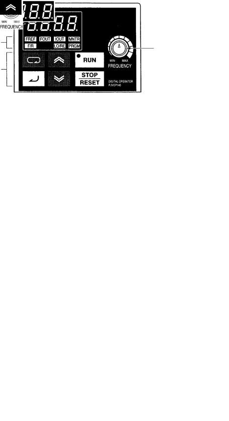
H Digital Operator
Data display
Simplified-LED
indicators |
FREQUENCY |
|
adjuster |
||
|
||
Operation keys |
|
Appearance |
Name |
Function |
|
|
|
|
Data display |
Displays relevant data items, such as frequency reference, |
|
|
output frequency, and parameter set values. |
|
|
|
|
FREQUENCY adjuster |
Sets the frequency reference within a range between 0 Hz |
|
|
and the maximum frequency. |
|
|
|
|
FREF indicator |
The frequency reference can be monitored or set while this |
|
|
indicator is lit. |
|
FOUT indicator |
The output frequency of the Inverter can be monitored |
|
|
while this indicator is lit. |
|
IOUT indicator |
The output current of the Inverter can be monitored while |
|
|
this indicator is lit. |
|
|
|
|
MNTR indicator |
The values set in U01 through U18 are monitored while |
|
|
this indicator is lit. |
|
F/R indicator |
The direction of rotation can be selected while this |
|
|
indicator is lit when operating the Inverter with the RUN |
|
|
Key. |
|
|
|
|
LO/RE indicator |
The operation of the Inverter through the Digital Operator |
|
|
or according to the set parameters is selectable while this |
|
|
indicator is lit. |
|
|
Note This status of this indicator can be only monitored |
|
|
while the Inverter is in operation. Any RUN command |
|
|
input is ignored while this indicator is lit. |
|
PRGM indicator |
The parameters in n001 through n179 can be set or |
|
|
monitored while this indicator is lit. |
|
|
Note While the Inverter is in operation, the parameters can |
|
|
be only monitored and only some parameters can be |
|
|
changed. Any RUN command input is ignored while |
|
|
this indicator is lit. |
|
|
|
|
Mode Key |
Switches the simplified-LED (setting and monitor) item |
|
|
indicators in sequence. |
|
|
Parameter being set will be canceled if this key is pressed |
|
|
before entering the setting. |
|
|
|
|
Increment Key |
Increases multi-function monitor numbers, parameter |
|
|
numbers, and parameter set values. |
|
|
|
1-6

Overview |
|
Chapter 1 |
|
|
|
|
|
Appearance |
Name |
Function |
|
|
|
|
|
|
Decrement Key |
Decreases multi-function monitor numbers, parameter |
|
|
|
numbers, and parameter set values. |
|
|
|
|
|
|
Enter Key |
Enters multi-function monitor numbers, parameter |
|
|
|
numbers, and internal data values after they are set or |
|
|
|
changed. |
|
|
|
|
|
|
RUN Key |
Starts the Inverter running when the 3G3MV is in operation |
|
|
|
with the Digital Operator. |
|
|
|
|
|
|
STOP/RESET Key |
Stops the Inverter unless parameter n007 is set to disable |
|
|
|
the STOP Key. Functions as a Reset Key when an Inverter |
|
|
|
error occurs. (See note.) |
|
Note For safety reasons, the reset will not work while a RUN command (forward or reverse) is in effect. Wait until the RUN command is OFF before resetting the Inverter.
1-7

Overview |
Chapter 1 |
|
|
|
|
1-3 New Features
New features have been added to 3G3MV-Series models with 5.5-kW and 7.5-kW capacities (i.e., the 3G3MV-A2055/A2075/ A4055/A4075). These features are outlined below and explained in detail in Chapter 6.
H New Features for 3G3MV-A2055/A2075/A4055/A4075 Only
D Enclosure Rating: Closed Wall-mounting Conforming to IP20/NEMA1
The 5.5-kW and 7.5-kW Inverters have closed wall-mounting specifications that conform to IP20/NEMA1, so they can operate in an ambient temperature range of –10 to 40°C.
Note To operate this Inverter within an ambient temperature range of –10 to 50°C, remove the top and bottom covers to convert it to a panel-mounting model (IP00).
D Default Settings Changed for V/f Patterns (Parameters: n011 to n017)
For 5.5-kW and 7.5-kW Inverters, two of the default settings have been changed. The default settings for the middle output frequency voltage (VC) (n015) and the minimum output frequency voltage (VMIN (n017) have both been changed to 10 V for 200-V-class models and to 20 V for 400-V-class models.
DInverter Overheating Warning Input (Parameters: n050 to n056; Fault Display: oH3)
An Inverter overheating warning input has been added as a new function that can be set for multi-func- tion inputs 1 to 7 (n050 to n056). When this warning is input, an oH3 fault (nonfatal error) will be displayed. This input can be used for functions such as thermal contact connections for peripheral overheating detection.
D Frequency Reference Loss Detection (Parameter: n064)
When the frequency is referenced using analog frequency reference inputs (0 to 10 V/4 to 20 mA/0 to 20 mA), this function detects sudden changes in analog inputs as errors (disconnection, short circuit, breakdown, etc.) and outputs the frequency reference loss output that is set in multi-function outputs 1 to 3 (n057 to n059). After the change is detected, operation continues at 80% of the frequency reference prior to the change.
D Accumulated Operating Time (Monitor: U-13; Parameters: n087, n088)
This function calculates and stores in memory the Inverter’s accumulated power-ON time or RUN time. Use it for checking and determining the maintenance schedule.
D Speed Search Adjustment (Parameters: n101, n102)
A function has been added for adjusting the speed search. (The speed search is a function for detecting and smoothly controlling the speed of a free running motor.) The speed search operating time and search level can be adjusted.
DInput Open-phase Detection
(Parameters: n166, n167; Fault Display: PF)
This function detects the Inverter’s input power supply open phase. Open phases are detected through main circuit voltage fluctuations, so this function can also be used for detecting abnormal voltage fluctuations in the input power supply voltage.
1-8
Overview |
Chapter 1 |
|
|
|
|
DOutput Open-phase Detection (Parameters: n168, n169; Fault Display: LF)
This function detects open phases between the Inverter output and the motor.
D Ground Fault Detection (Fault Display: GF)
This function detects ground faults between the Inverter output and the motor.
D Load Short-circuit Detection (Fault Display: SC)
Prior to an Inverter output, this function detects whether the output is short-circuited. If short-circuiting occurs during an output, it detects an overcurrent (oC).
H New Features for All 3G3MV Models
D Communications Error Monitor (Monitor: U-15)
This function displays communications errors that occur during serial communications (RS-422/RS-485). The errors that are displayed have the same content as the general serial communications error at register number 003D Hex.
DPulse Train Frequency Reference Input Filter Constant (Parameter: n076)
This function sets the primary lag digital filter for pulse train frequency reference inputs.
D Multi-function Analog Inputs (Parameters: n077 to n079)
A function has been added to enable setting the Digital Operator’s multi-function analog voltage (current) inputs. It can set auxiliary analog inputs such as auxiliary frequency references and frequency reference bias or gain.
Note If multi-function analog inputs are set for use with PID control, no other multi-function analog input functions can be set or they will overlap.
HNew Features for 3G3MV Series (Software Version 0028 (3.7 kW or Less) or Higher)
DOperation Continuation Timer Added to the Momentary Power Interruption Compensation Parameter (n081)
Parameter n081 can be set so that operation will not restart after a power interruption until the RUN signal is ON for the time specified for the parameter (5 to 100 x 0.1 s). If the parameter is set to 2 (Inverter restarts when power is restored), operation will recover for all Inverters at the same time, meaning the power supply capacity must be sufficient for the maximum current. By setting timers to between 0.5 and 10.0 s, differences can be created in the Inverter recovery time to prevent tripping the power supply breaker, which could happen if all Inverters recovered at the same time.
DEnter Command (Saving Parameters to EEPROM) Operation Selection (n170) To Enable the Enter Command at Any Time
Previously, operation had to be stopped to use the Enter command to saved changes made to parameters during operation using DeviceNet or RS-422/485 communications. This sometimes caused saving parameters to be forgotten when a system could not be stopped immediately after changing parameters, causing the need to reset the parameters again when they were lost at the next power interruption or system shutdown. The new parameter n170 can be set to 1 to enable using the Enter command to write parameters to EEPROM even during operation.
1-9


 2
2


Chapter 2
 Design
2-1 Installation
2-2 Wiring
Design |
Chapter 2 |
|
|
|
|
2-1 Installation
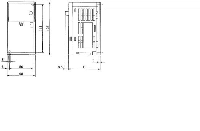
2-1-1 Dimensions
D3G3MV-A2001 to 3G3MV-A2007 (0.1 to 0.75 kW) 3-phase 200-V AC Input 3G3MV-AB001 to 3G3MV-AB004 (0.1 to 0.4 kW) Single-phase 200-V AC Input
Rated voltage |
Model 3G3MV- |
|
Dimensions (mm) |
|
Weight (kg) |
|
|
|
|
|
D |
|
t |
|
|
|
|
|
|
|
|
|
|
3-phase 200 V AC |
A2001 |
76 |
|
3 |
|
Approx. 0.6 |
|
|
|
|
|
|
|
|
|
|
A2002 |
76 |
|
3 |
|
Approx. 0.6 |
|
|
|
|
|
|
|
|
|
|
A2004 |
108 |
|
5 |
|
Approx. 0.9 |
|
|
|
|
|
|
|
|
|
|
A2007 |
128 |
|
5 |
|
Approx. 1.1 |
|
|
|
|
|
|
|
|
|
Single-phase 200 V AC |
AB001 |
76 |
|
3 |
|
Approx. 0.6 |
|
|
|
|
|
|
|
|
|
|
AB002 |
76 |
|
3 |
|
Approx. 0.7 |
|
|
|
|
|
|
|
|
|
|
AB004 |
131 |
|
5 |
|
Approx. 1.0 |
|
2-2
 Loading...