


Simple, Compact Inverters
 3G3JVSeries
Note: Do not use this document to operate the Unit.
OMRON Corporation |
Regional Headquarters |
FA Systems Division H.Q. |
OMRON EUROPE B.V. |
66 Matsumoto |
Wegalaan 67-69, NL-2132 JD Hoofddorp |
Mishima-city, Shizuoka 411-8511 |
The Netherlands |
Japan |
Tel:(31)2356-81-300/Fax:(31)2356-81-388 |
Tel:(81)55-977-9181 |
OMRON ELECTRONICS LLC |
Fax:(81)55-977-9045 |
1 East Commerce Drive, Schaumburg, IL 60173 U.S.A. |
|
Tel:(1)847-843-7900/Fax:(1)847-843-8568 |
|
OMRON IDM Controls |
|
9510 North Houston, Tx. 77088 U.S.A. |
|
Tel: (1)800-395-4106/Fax: (1)713-849-4666 |
|
OMRON ASIA PACIFIC PTE. LTD. |
|
83 Clemenceau Avenue, #11-01, UE Square, |
|
Singapore 239920 |
|
Tel:(65)6835-3011/Fax:(65)6835-2711 |
Authorized Distributor:
Note: Specifications subject to change without notice. |
Cat.No.I905-E1-05 |
|
Printed in Japan |
|
0204-1M |

There has been a great demand for inverters that provide easier motor speed control. OMRON's simple, compact 3G3JV Series meets the demand.
The 3G3JV Inverters provide versatile functions and ensure powerful performance. The front panel of the 3G3JV Inverter has a frequency adjuster that makes it possible to start the motor and easily control the motor speed.
The 3G3JV Inverters are easy to mount and operate and support a wide range of applications for efficient motor control.
Actual
Size
Three-phase 100 W at 200 V 68 x 128 x 78.5 mm (W x H x D)
The frequency adjuster on the front panel makes it possible to easily adjust the speed of the motor.
The Inverter can be operated immediately after the power is turned ON.
The 3G3JV Inverter performs versatile speed control, such as multi-step speed control up to a maximum of nine steps, acceleration and deceleration (UP/DOWN) control, and jog operations. Furthermore, the 3G3JV Inverter provides a variety of useful functions, including slip compensation, overtorque detection, and speed search functions.
The cooling fan can be easily mounted or dismounted. The cooling fan can also be turned on only when the 3G3JV Inverter is in operation, prolonging the life of the fan.
The 3G3JV Inverters are compact and space-saving to mount easily into a panel.
C o n t e n t s
Features |
2 |
Applications |
4 |
Nomenclature |
6 |
Using Digital Operator |
8 |
List of Parameters |
11 |
Function of Each Parameter |
14 |
Specifications |
22 |
Dimensions |
27 |
Standard Connections |
28 |
Protective and Diagnostic Functions |
29 |
Options |
34 |
Inverter Models |
47 |
This catalog provides information for the selection of models, but does not provide operational precautions. For information on the operation of the 3G3JV Inverters and operational precautions, be sure to read the operation manual.
The 3G3JV Inverter incorporates main circuit terminals arranged in two rows on the top and bottom of the housing, making it possible to
mount the 3G3JV Inverter like a contactor. The optional DIN Track Mounting Bracket makes it possible to easily mount a 3G3JV Inverter to a DIN track.
The 3G3JV Inverter supports a variety of I/O, such as analog inputs between 0 and 10V, 4 to 20 mA, or 0 to 20 mA, multifunction I/O, and analog monitor outputs. Multi-function inputs can set to either PNP or NPN, providing flexibility in input signals.
Standard models meet CE and UL/cUL standards.
C
2 |
3 |

Conventionalti l Systemst
 Relay contact welding occurs, which may put the system and operators in danger. Furthermore, the life of the system is comparatively short.
 The system employs a gearbox for
speed control, the designing and Breaker adjustment of which require time and
labor.
|
To ensure the safety of the system, the |
|
|
|
||||
|
|
|
|
|||||
|
system needs peripheral safety |
|
Open-phase |
|
|
|
||
|
devices, the wiring of which requires |
detection |
|
|
|
|||
|
time and labor. |
|
|
|
|
|
|
|
|
The motor always rotates at top speed, |
|
|
|
||||
|
|
|
|
|||||
|
|
|
|
|||||
|
consuming a high amount of power. |
|
|
|
|
|
||
|
A strong shock is produced when the |
|
|
|
|
|
||
|
|
|
|
|
|
|||
|
|
|
|
|
|
|||
|
motor is driven, which may cause |
|
|
|
|
|
|
|
|
loads to shift, deteriorate the quality of |
|
|
|
|
|
||
|
products, or put the system and |
|
|
|
|
|
|
|
|
operators in danger. |
|
Contactor |
|
|
|
||
|
Three-phase |
|
|
|
|
|
|
|
|
inductive |
|
|
|
|
|
|
|
|
motor |
|
|
|
|
|
|
|
|
|
|
|
|
|
Current leakage |
|
|
|
Gear box |
Starter |
detection |
|
||||
|
|
|
|
|||||
|
|
|
|
|
|
|
|
|
|
|
|
|
|
|
|
|
|
|
|
|
|
|
|
|
|
|
3G3JV InverterI t Solutionsl ti
 A 3G3JV Inverter has no mechanical relay contacts
long-life system  A 3G3JV Inverter speed control, control for up
and deceleration and jog operations
 A 3G3JV Inverter protective
speed current protection, and
 A 3G3JV Inverter flexible speeds range of the
power consumption  A 3G3JV Inverter soft-stop functions, from shifting quality, while system.
Three-phase inductive motor
Breaker
3G3JV Inverter
Conventionalti l Systemst |
|
|
|
3G3JV InverterI t Solutionsl ti |
|
|
|
A |
|
|
|
A 3G3JV |
|
|
|
|
|
|
||
|
|
|
|
|
||
|
the |
|
|
|
soft-stop |
|
|
load |
|
|
|
from shifting |
|
|
|
|
|
|
product quality |
|
|
|
|
|
|
of the system |
|
|
The |
|
|
|
The 3G3JV |
|
|
|
|
|
|
||
|
|
|
|
|
||
|
|
|
|
|
a maximum |
|
|
motor |
Breaker |
|
|
and ensure |
|
|
used |
|
|
torque in the |
Breaker |
|
|
|
|
|
|||
|
|
|
|
|
|
|
|
The |
|
|
|
A three-phase |
|
|
|
|
|
|
||
|
|
|
|
|
fluctuation |
|
|
|
|
|
|
|
|
|
by |
|
|
|
phase motor, |
|
|
The |
|
|
|
operation of |
|
|
|
|
|
|
||
|
limited |
|
|
|
A 3G3JV |
|
|
|
|
|
|
contact outputs |
|
|
|
|
|
|
controller, such |
|
|
|
|
|
|
Controller. |
3G3JV |
|
|
|
|
|
A wide range |
|
|
|
|
|
|
||
|
|
|
|
|
Inverter |
|
|
|
|
|
|
|
|
|
|
|
|
|
Three-phase |
|
|
|
|
|
|
inductive motor |
|
|
Gear box |
Speed controller |
|
|
|
|
|
|
|
|
|
|
|
A 3G3JV Inverter provides soft-start and soft-stop functions to prevent loads from shifting. Furthermore, a 3G3JV Inverter performs flexible speed control of the conveyor up to nine steps.
A 3G3JV Inverter provides optimum control of fan speed according to the room temperature. The 3G3JV Inverter has no mechanical relay contacts, ensuring the safety and reliability of the system compared with the ON/OFF control of contactors. Optimum control of fan speed also saves energy.
A 3G3JV Inverter performs flexible speed control of a compact agitator or separator.
A 3G3JV Inverter provides multi-step speed control to open and close an electric shutter safely and efficiently. The shutter opens quickly at a high speed, but closes at a medium-range speed while the system checks the safety of the operation and decelerates to low speed before it is fully closed to prevent people from being caught by the shutter.
4 |
5 |
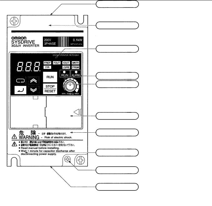
Nomenclature

 Panel
Panel
Top protection cover:
Remove this cover when wiring the upper terminal block.
Upper terminal block:
A terminal block on the input side of the main circuit.
Digital Operator:
Used to set parameters, perform various monitoring, and start and stop the Inverter.
ALARM indicator:
RUN indicator:
Displays the operating status of the Inverter.
Alarm (Red): Lights when an error occurs. Flashes when a warning occurs.
RUN (Green): Flashes when no RUN command is input during normal status. Lights when a RUN command is input during normal status.
Optional cover:
Remove this cover when setting the input method selector.
Front cover:
Remove this cover when wiring the upper or lower terminal block.
Front cover mounting screw:
A screw for fixing the front cover.
Lower terminal blocks:
A terminal block on the output side of the main circuit and a terminal block for the control circuit.
Bottom protection cover:
Remove this cover when wiring the lower terminal blocks.
6
Nomenclature

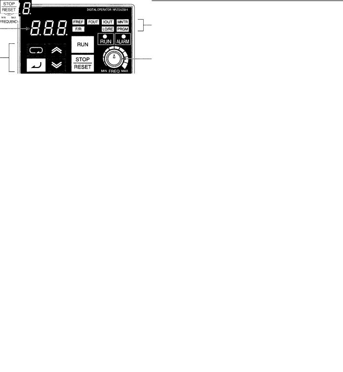
 Digital Operator
Data display |
Indicators |
(Setting/Monitor item |
|
|
indicators) |
Keys |
FREQ adjuster |
Appearance |
Name |
Function |
|
|
|
|
Data display |
Displays relevant data items, such as frequency reference, output frequency, |
|
|
and parameter set values. |
|
|
|
|
Frequency adjuster |
Sets the frequency reference within a range between 0 Hz and the maximum |
|
|
frequency. |
|
|
|
|
Frequency reference |
The frequency reference can be monitored or set while this indicator is lit. |
|
indicator |
|
|
|
|
|
Output frequency |
The output frequency of the Inverter can be monitored while this indicator is |
|
indicator |
lit. |
|
|
|
|
Output current |
The output current of the Inverter can be monitored while this indicator is lit. |
|
indicator |
|
|
|
|
|
Multi-function |
The values set in U01 through U10 are monitored while this indicator is lit. |
|
monitor indicator |
|
|
|
|
|
Forward/Reverse |
The direction of rotation can be selected while this indicator is lit when |
|
selection indicator |
operating the Inverter with the RUN Key. |
|
|
|
|
Local/Remote |
The operation of the Inverter through the Digital Operator or according to the |
|
selection indicator |
set parameters is selectable while this indicator is lit. (See note 1.) |
|
|
|
|
Parameter setting |
The parameters in n01 through n79 can be set or monitored while this |
|
indicator |
indicator is lit. (See note 2.) |
|
|
|
|
Mode Key |
Switches the setting and monitor item indicators in sequence. |
|
|
Parameter being set will be canceled if this key is pressed before entering |
|
|
the setting. |
|
|
|
|
Increment Key |
Increases multi-function monitor numbers, parameter numbers, and |
|
|
parameter set values. |
|
|
|
|
Decrement Key |
Decreases multi-function monitor numbers, parameter numbers, and |
|
|
parameter set values. |
|
|
|
|
Enter Key |
Enters multi-function monitor numbers, parameter numbers, and internal |
|
|
data values after they are set or changed. |
|
|
|
|
RUN Key |
Starts the Inverter running when the 3G3JV is in operation with the Digital |
|
|
Operator. |
|
|
|
|
STOP/RESET Key |
Stops the Inverter unless parameter n06 is set to disable the STOP Key. |
|
|
Used to reset the Inverter when an error occurs. (See note 3.) |
|
|
|
Note: 1. The status of the local/remote selection indicator can be only monitored while the Inverter is in operation. Any RUN command input is ignored while this indicator is lit.
2.While the Inverter is in operation, the parameters can be only monitored and only some parameters can be changed. Any RUN command input is ignored while the parameter setting indicator is lit.
3.For safety reasons, the reset function cannot be used while an operation instruction (forward/reverse) is being input. Turn the operation instruction OFF before using this function.
7

Using Digital Operator

 Selecting Indicators
Power ON
represents a lit indicator.
Frequency |
Output |
Output current |
|
reference |
frequency |
||
|
Parameter |
Local/Remote |
Direction of |
Multi-function |
settings |
selection |
rotation |
monitor |
Parameter n01 |
Remote mode |
Forward |
Frequency reference |
Parameter n02 |
Local mode |
Reverse |
Output frequency |
Other parameters |
Other monitor items |
Note: If the power is turned OFF with the FOUT or IOUT indicator lit, the same indicator will light when the power is turned ON again. In other cases, the FREF indicator will light when the power is turned ON.

 Example of Frequency Reference Settings
Flashing
Key sequence |
Indicator |
Display example |
|
Explanation |
|
|
|
|
|
|
|
|
Power ON |
|
|
|
|
Note |
If the FREF indicator has not been lit, press the Mode |
|
|
|
|
Key repeatedly until the FREF indicator is lit. |
|
|
|
|
|
|
|
|
Use the Increment or Decrement Key to set the frequency |
|
|
|
|
reference. |
|
|
|
|
The data display will flash while the frequency reference is |
|
|
|
|
set. (see note 1) |
|
|
|
|
|
|
|
|
|
Press the Enter Key so that the set value will be entered and |
|
|
|
|
the data display will be lit. (see note 1) |
|
Note: The Enter Key need not be pressed when performing the setting for n08. The frequency reference will change when the set value is changed with the Increment or Decrement Key while the data display is continuously lit.
8

Using Digital Operator

 Example of Multi-function Display
|
Frequency |
DC bus |
Monitor |
|
|
reference |
voltage |
data |
|
|
|
|
|
Complete |
|
|
|
|
|
Key sequence |
Indicator |
|
Display |
Explanation |
|
|
|
|
|
|
|
|
|
Power ON |
|
|
|
|
|
|
|
|
|
Press the Mode Key repeatedly until the MNTR indicator is |
|
|
|
|
lit. |
|
|
|
|
U01 will be displayed. |
|
|
|
|
|
|
|
|
|
Use the Increment or Decrement Key to select the monitor |
|
|
|
|
item to be displayed. |
|
|
|
|
|
|
|
|
|
Press the Enter Key so that the data of the selected monitor |
|
|
|
|
item will be displayed. |
|
|
|
|
|
|
|
|
|
The monitor number display will appear again by pressing |
|
|
|
|
the Mode Key. |
Status Monitor
Item |
Display |
Display |
|
Function |
|
|
|
unit |
|
|
|
|
|
|
|
||
U01 |
Frequency reference |
Hz |
Monitors the frequency reference. (Same as FREF) |
||
|
|
|
|
||
U02 |
Output frequency |
Hz |
Monitors the output frequency. (Same as FOUT) |
||
|
|
|
|
||
U03 |
Output current |
A |
Monitors the output current. (Same as IOUT) |
||
|
|
|
|
||
U04 |
Output voltage |
V |
Monitors the internal output voltage reference value of the Inverter. |
||
|
|
|
|
||
U05 |
DC bus voltage |
V |
Monitors the DC voltage of the internal main circuit of the Inverter. |
||
|
|
|
|
|
|
U06 |
Input terminal status |
--- |
Shows the ON/OFF status of inputs. |
|
|
|
|
|
|
: Input ON |
: No input |
|
|
|
|
Terminal S1: Forward/Stop |
|
|
|
|
|
Terminal S2: Multi-function input 1 (S2) |
|
|
|
|
|
Terminal S3: Multi-function input 2 (S3) |
|
|
|
|
Not |
Terminal S4: Multi-function input 3 (S4) |
|
|
|
|
Terminal S5: Multi-function input 4 (S5) |
||
|
|
|
used |
|
|
U07 |
Output terminal |
--- |
Shows the ON/OFF status of outputs. |
|
|
|
status |
|
|
|
|
|
|
|
|
: Closed |
: Open |
|
|
|
Not |
Terminal MA: Multi-function contact |
|
|
|
|
used |
output |
|
|
|
|
|
|
|
U09 |
Error log (most |
--- |
Displays the latest error. |
|
|
|
recent one) |
|
|
|
|
|
|
|
Error |
|
|
|
|
|
|
|
|
U10 |
Software No. |
--- |
OMRON use only. |
|
|
9
Using Digital Operator

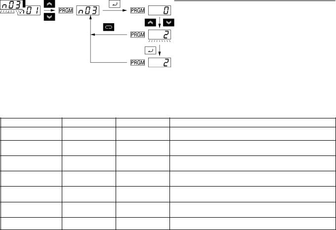
 Example of Parameter Settings
The following example shows how to set 2 to enable the frequency reference control terminal for 0- to 10-V input in parameter n03 (Frequency Reference Selection).
Enable the frequency reference Cancels set control terminal for 0- to 10-V input. data.
Complete
In approximately 1 s.
Key sequence |
Indicator |
Display example |
Explanation |
Power ON
Press the Mode Key repeatedly until the PRGM indicator is lit.
Use the Increment or Decrement Key to set the parameter number.
Press the Enter Key.
The data of the selected parameter number will be displayed.
Use the Increment or Decrement Key to set the data. At that time the display will flash.
Press the Enter Key so that the set value will be entered and the data display will be lit. (see note 1)
In approximately 1 s. |
The parameter number will be displayed. |
Note: 1. To cancel the set value, press the Mode Key instead. The parameter number will be displayed.
2.There are parameters that cannot be changed while the Inverter is in operation. Refer to the list of parameters. When attempting to change such parameters, the data display will not change by pressing the Increment or Decrement Key.
10

List of Parameters

 List of Parameters
Param- |
Name |
Description |
Setting |
Unit of |
Default |
Changes |
Refer- |
|
eter |
|
|
range |
setting |
setting |
during op- |
ence |
|
No. |
|
|
|
(see note 2) |
|
eration |
page |
|
|
|
|
|
|
|
|
|
|
n01 |
Parameter |
Used to prohibit parameters to be written, sets |
0, 1, 6, 8, 9 |
1 |
1 |
No |
14 |
|
|
write-prohibit selection/ |
parameters, or change the monitor range of |
|
|
|
|
|
|
|
parameter initialization |
parameters. |
|
|
|
|
|
|
|
|
Used to initialize parameters to default values. |
|
|
|
|
|
|
|
|
|
|
|
|
|
|
|
n02 |
Operation mode selec- |
Used to select the input method for the RUN and STOP |
0, 1 |
1 |
0 |
No |
14 |
|
|
tion |
commands in remote mode. |
|
|
|
|
|
|
|
|
|
|
|
|
|
|
|
n03 |
Frequency reference |
Used to set the input method for the frequency refer- |
0 to 4 |
1 |
0 |
No |
14 |
|
|
selection |
ence in remote mode. |
|
|
|
|
|
|
|
|
|
|
|
|
|
|
|
n04 |
Interruption mode selec- |
Used to set the stopping method for use when the |
0, 1 |
1 |
0 |
No |
14 |
|
|
tion |
STOP command is input. |
|
|
|
|
|
|
|
|
|
|
|
|
|
|
|
n05 |
Reverse rotation-prohibit |
Used to select the operation with the reverse command |
0, 1 |
1 |
0 |
No |
14 |
|
|
selection |
input. |
|
|
|
|
|
|
|
|
|
|
|
|
|
|
|
n06 |
STOP/RESET Key func- |
Used to select the stop method in remote mode with |
0, 1 |
1 |
0 |
No |
14 |
|
|
tion selection |
n02 for operation mode selection set to 1. |
|
|
|
|
|
|
|
|
|
|
|
|
|
|
|
n07 |
Frequency selection in |
Used to set the input method for the frequency refer- |
0, 1 |
1 |
0 |
No |
14 |
|
|
local mode |
ence in local mode. |
|
|
|
|
|
|
|
|
|
|
|
|
|
|
|
n08 |
Key sequential |
Used to enable the Enter Key for setting the frequency |
0, 1 |
1 |
0 |
No |
14 |
|
|
frequency setting |
reference with the Increment and Decrement Keys. |
|
|
|
|
|
|
|
|
|
|
|
|
|
|
|
n09 |
Maximum frequency |
Used to set the V/f pattern as the basic characteristic of |
50.0 to 400 |
0.1 Hz |
60.0 |
No |
14 |
|
|
(FMAX) |
the Inverter with output voltage per frequency set. |
|
|
|
|
|
|
|
|
Note Set the parameters so that the following condition |
|
|
|
|
|
|
n10 |
Maximum voltage |
1 to 255 |
1 V |
200 (see |
No |
14 |
||
|
(VMAX) |
will be satisfied. |
(see note 1) |
|
note 1) |
|
|
|
|
|
n14 x n12 < n11 x n09 |
|
|
|
|
|
|
n11 |
Maximum voltage fre- |
0.2 to 400 |
0.1 Hz |
60.0 |
No |
14 |
||
Note The value set in n13 will be ignored if parameters |
||||||||
|
quency (FA) |
|
|
|
|
|
||
|
|
n14 and n12 are the same in value. |
|
|
|
|
|
|
n12 |
Middle output |
0.1 to 399 |
0.1 Hz |
1.5 |
No |
14 |
||
|
||||||||
|
frequency (FB) |
|
|
|
|
|
|
|
|
|
|
|
|
|
|
|
|
n13 |
Middle output |
|
1 to 255 |
1 V |
12 (see |
No |
14 |
|
|
frequency voltage (VC) |
|
(see note 1) |
|
note 1) |
|
|
|
|
|
|
|
|
|
|
|
|
n14 |
Minimum output |
|
0.1 to 10.0 |
0.1 Hz |
1.5 |
No |
14 |
|
|
frequency (FMIN) |
|
|
|
|
|
|
|
|
|
|
|
|
|
|
|
|
n15 |
Minimum output |
|
1 to 50 |
1 V |
12 (see |
No |
14 |
|
|
frequency voltage |
|
(see note 1) |
|
note 1) |
|
|
|
|
(VMIN) |
|
|
|
|
|
|
|
|
|
|
|
|
|
|
|
|
n16 |
Acceleration time 1 |
Acceleration time: The time required to go from 0% to |
0.0 to 999 |
0.1 s |
10.0 |
Yes |
15 |
|
|
|
100% of the maximum frequency. |
|
|
|
|
|
|
|
|
Deceleration time: The time required to go from 100% |
|
|
|
|
|
|
n17 |
Deceleration time 1 |
|
|
10.0 |
Yes |
15 |
||
|
|
to 0% of the maximum frequency. |
|
|
|
|
|
|
|
|
Note The actual acceleration or deceleration time is ob- |
|
|
|
|
|
|
n18 |
Acceleration time 2 |
|
|
10.0 |
Yes |
15 |
||
tained from the following formula. |
|
|
||||||
|
|
|
|
|
|
|
||
|
|
Acceleration/Deceleration time = (Acceleration/De- |
|
|
|
|
|
|
n19 |
Deceleration time 2 |
celeration time set value) × (Frequency reference |
|
|
10.0 |
Yes |
15 |
|
|
|
value) ÷ (Max. frequency) |
|
|
|
|
|
|
|
|
|
|
|
|
|
|
|
n20 |
S-shape acceleration/de- |
Used to set S-shape acceleration/deceleration charac- |
0 to 3 |
1 |
0 |
No |
15 |
|
|
celeration characteristic |
teristics. |
|
|
|
|
|
|
|
|
|
|
|
|
|
|
|
n21 |
Frequency reference 1 |
Used to set internal frequency references. |
0.0 to max. |
0.1 Hz |
6.0 |
No |
15 |
|
|
|
Note Frequency reference 1 is enabled in remote mode |
frequency |
|
|
|
|
|
n22 |
Frequency reference 2 |
|
0.0 |
No |
15 |
|||
|
|
|||||||
|
|
with n03 for frequency reference selection set to 1. |
|
|
|
|
|
|
n23 |
Frequency reference 3 |
|
|
0.0 |
No |
15 |
||
Note These frequency references are selected with mul- |
|
|
||||||
|
|
|
|
|
|
|
||
n24 |
Frequency reference 4 |
|
|
0.0 |
No |
15 |
||
ti-step speed references (multi-function input). See |
|
|
||||||
|
|
|
|
|
|
|
||
n25 |
Frequency reference 5 |
the reference pages for the relationship between |
|
|
0.0 |
No |
15 |
|
n26 |
Frequency reference 6 |
multi-step speed references and frequency refer- |
|
|
0.0 |
No |
15 |
|
ences. |
|
|
||||||
|
|
|
|
|
|
|
||
n27 |
Frequency reference 7 |
|
|
0.0 |
No |
15 |
||
|
|
|
||||||
|
|
|
|
|
|
|
|
|
n28 |
Frequency reference 8 |
|
|
|
0.0 |
No |
15 |
|
|
|
|
|
|
|
|
|
|
n29 |
Inching frequency com- |
Used to set the inching frequency command. |
|
|
6.0 |
No |
15 |
|
|
mand |
|
|
|
|
|
|
Note: 1. With 400-class Inverters, the default settings and maximum values setting ranges for n10, n13, and n15 are double those given in the table.
2. Values longer than 3 digits are rounded up to the next unit multiple.
11

List of Parameters
Param- |
Name |
|
Description |
Setting |
Unit of |
Default |
Changes |
Reference |
|
eter |
|
|
|
range |
setting |
setting |
during op- |
page |
|
No. |
|
|
|
|
(see note) |
|
eration |
|
|
|
|
|
|
|
|
|
|
||
n30 |
Frequency reference |
Used to set the upper and lower frequency reference |
0 to 110 |
1% |
100 |
No |
16 |
||
|
upper limit |
limits in percentage based on the maximum frequency |
|
|
|
|
|
||
|
|
as 100%. |
|
|
|
|
|
||
n31 |
Frequency reference |
0 to 110 |
1% |
0 |
No |
16 |
|||
|
|
||||||||
|
lower limit |
|
|
|
|
|
|
|
|
|
|
|
|
|
|
|
|
||
n32 |
Rated motor current |
Used to set the rated motor current for motor overload |
0.0 to 120% |
0.1 A |
Varies |
No |
16 |
||
|
|
detection (OL1) based on the rated motor current. |
of rated out- |
|
with the |
|
|
||
|
|
Note Motor overload detection (OL1) is disabled by set- |
put current |
|
capacity. |
|
|
||
|
|
ting the parameter to 0.0. |
|
|
|
|
|
||
|
|
|
|
|
|
|
|
||
n33 |
Motor protection |
Used to set the motor overload detection (OL1) for the |
0 to 2 |
1 |
0 |
No |
16 |
||
|
characteristics |
electronic thermal characteristics of the motor. |
|
|
|
|
|
||
|
|
|
|
|
|
|
|
||
n34 |
Motor protective |
Used to set the electric thermal characteristics of the |
1 to 60 |
1 min |
8 |
No |
16 |
||
|
time setting |
motor to be connected in 1-minute increments. |
|
|
|
|
|
||
|
|
|
|
|
|
|
|
||
n35 |
Cooling fan opera- |
Used to operate the Cooling Fan of the Inverter while |
0, 1 |
1 |
0 |
No |
16 |
||
|
tion function |
the Inverter is turned on or only while the Inverter is in |
|
|
|
|
|
||
|
|
operation. |
|
|
|
|
|
||
|
|
|
|
|
|
|
|
||
n36 |
Multi-function input 1 |
Used to select the functions of multi-function input ter- |
2 to 22 |
1 |
2 |
No |
16 |
||
|
(Input terminal S2) |
minals S2 through S5. |
|
|
|
|
|
||
|
|
|
|
|
|
|
|
|
|
n37 |
Multi-function input 2 |
|
|
0 to 22 |
1 |
5 |
No |
16 |
|
|
(Input terminal S3) |
|
|
|
|
|
|
|
|
|
|
|
|
|
|
|
|
|
|
n38 |
Multi-function input 3 |
|
|
2 to 22 |
1 |
3 |
No |
16 |
|
|
(Input terminal S4) |
|
|
|
|
|
|
|
|
|
|
|
|
|
|
|
|
|
|
n39 |
Multi-function input 4 |
|
|
2 to 34 |
1 |
6 |
No |
16 |
|
|
(Input terminal S5) |
|
|
|
|
|
|
|
|
|
|
|
|
|
|
|
|
||
n40 |
Multi-function output |
Used to select the functions of multi-function output |
0 to 7, 10 to |
1 |
1 |
No |
17 |
||
|
(MA/MB and MC |
terminals. |
17 |
|
|
|
|
||
|
output terminals) |
|
|
|
|
|
|
|
|
|
|
|
|
|
|
|
|
||
n41 |
Frequency reference |
Used to the input characteristics of analog frequency |
0 to 255 |
1% |
100 |
Yes |
17 |
||
|
gain |
references. |
|
|
|
|
|
||
|
|
|
|
|
|
|
|
|
|
n42 |
Frequency reference |
|
|
–99 to 99 |
1% |
0 |
Yes |
17 |
|
|
bias |
|
|
|
|
|
|
|
|
|
|
|
|
|
|
|
|
||
n43 |
Analog frequency |
Used to set the digital filter with a first-order lag for ana- |
0.00 to 2.00 |
0.01 s |
0.10 |
No |
17 |
||
|
reference filter time |
log frequency references to be input. |
|
|
|
|
|
||
|
|
|
|
|
|
|
|
||
n44 |
Analog monitor |
Used to set the output frequency or current as a moni- |
0, 1 |
1 |
0 |
No |
17 |
||
|
output |
tored item. |
|
|
|
|
|
||
|
|
|
|
|
|
|
|
||
n45 |
Analog monitor |
Used to set the output characteristics of analog monitor |
0.00 to 2.00 |
0.01 |
1.00 |
Yes |
17 |
||
|
output gain |
output. |
|
|
|
|
|
|
|
|
|
|
|
|
|
|
|
||
n46 |
Carrier frequency |
Used to set the carrier frequency. |
1 to 4, 7 to |
1 |
Varies |
No |
18 |
||
|
selection |
|
|
9 |
|
with the |
|
|
|
|
|
|
|
|
|
capacity. |
|
|
|
|
|
|
|
|
|
|
|
||
n47 |
Momentary power |
Used to specify the processing that is performed when |
0 to 2 |
1 |
0 |
No |
18 |
||
|
interruption com- |
a momentary power interruption occurs. |
|
|
|
|
|
||
|
pensation |
|
|
|
|
|
|
|
|
|
|
|
|
|
|
|
|
||
n48 |
Fault retry |
Used to set the number of times the Inverter is reset |
0 to 10 |
1 |
0 |
No |
18 |
||
|
|
and restarted automatically in the case the Inverter has |
|
|
|
|
|
||
|
|
an overvoltage fault, overcurrent fault, or ground fault. |
|
|
|
|
|
||
|
|
|
|
|
|
|
|
||
n49 |
Jump frequency 1 |
Used to set the frequency jump function. |
0.0 to 400 |
0.1 Hz |
0.0 |
No |
18 |
||
|
|
|
|
|
|
|
|
|
|
n50 |
Jump frequency 2 |
Note |
These values must satisfy the following condi- |
0.0 to 400 |
0.1 Hz |
0.0 |
No |
18 |
|
|
|
|
|
|
|
|
|||
n51 |
Jump width |
|
tion: n49 y n50 |
0.0 to 400 |
0.1 Hz |
0.0 |
No |
18 |
|
|
|
|
|
|
|
|
|
||
n52 |
DC control current |
Used to impose DC on the induction motor for braking |
0 to 100 |
1% |
50 |
No |
18 |
||
|
|
control. |
|
|
|
|
|
|
|
n53 |
Interruption DC |
|
0.0 to 25.5 |
0.1 s |
0.5 |
No |
18 |
||
|
|
||||||||
|
control time |
|
|
|
|
|
|
|
|
|
|
|
|
|
|
|
|
|
|
n54 |
Startup DC control |
|
|
0.0 to 25.5 |
0.1 s |
0.0 |
No |
18 |
|
|
time |
|
|
|
|
|
|
|
|
|
|
|
|
|
|
|
|
||
n55 |
Stall prevention |
Used to select a function to change the deceleration |
0, 1 |
1 |
0 |
No |
18 |
||
|
during deceleration |
time of the motor automatically so that there will be no |
|
|
|
|
|
||
|
|
overvoltage imposed on the motor during deceleration. |
|
|
|
|
|
||
|
|
|
|
|
|
|
|
||
n56 |
Stall prevention level |
Used to select a function to stop the acceleration of the |
30 to 200 |
1% |
170 |
No |
19 |
||
|
during acceleration |
motor automatically for stall prevention during |
|
|
|
|
|
||
|
|
acceleration. |
|
|
|
|
|
||
|
|
|
|
|
|
|
|
||
n57 |
Stall prevention level |
Used to select a function to reduce the output |
30 to 200 |
1% |
160 |
No |
19 |
||
|
during operation |
frequency of the Inverter automatically for stall |
|
|
|
|
|
||
|
|
prevention during operation. |
|
|
|
|
|
||
|
|
|
|
|
|
|
|
||
n58 |
Frequency detection |
Used to set the frequency to be detected. |
0.0 to 400 |
0.1 Hz |
0.0 |
No |
19 |
||
|
level |
|
|
|
|
|
|
|
|
Note: Values longer than 3 digits are rounded up to the next unit multiple.
12
List of Parameters
Param- |
Name |
|
Description |
Setting |
Unit of |
Default |
Changes |
Reference |
eter |
|
|
|
range |
setting |
setting |
during op- |
page |
No. |
|
|
|
|
(see note) |
|
eration |
|
|
|
|
|
|
|
|
|
|
n59 |
Overtorque |
Used to enable or disable overtorque detection and |
0 to 4 |
1 |
0 |
No |
19 |
|
|
detection function |
select the processing method after overtorque |
|
|
|
|
|
|
|
selection |
detection. |
|
|
|
|
|
|
|
|
|
|
|
|
|
|
|
n60 |
Overtorque |
Used to set overtorque detection level. |
30 to 200 |
1% |
160 |
No |
19 |
|
|
detection level |
|
|
|
|
|
|
|
|
|
|
|
|
|
|
|
|
n61 |
Overtorque |
Used to set the detection time of overtorque. |
0.1 to 10.0 |
0.1 s |
0.1 |
No |
19 |
|
|
detection time |
|
|
|
|
|
|
|
|
|
|
|
|
|
|
|
|
n62 |
UP/DOWN |
Used to store the adjusted frequency reference with the |
0, 1 |
1 |
0 |
No |
20 |
|
|
command frequency |
UP/DOWN function. |
|
|
|
|
|
|
|
memory |
|
|
|
|
|
|
|
|
|
|
|
|
|
|
|
|
n63 |
Torque |
Used to set the gain of the torque compensation |
0.0 to 2.5 |
0.1 |
1.0 |
Yes |
21 |
|
|
compensation gain |
function. |
|
|
|
|
|
|
|
|
|
|
|
|
|
|
|
n64 |
Motor rated slip |
Used to set the rated slip value of the motor in use. |
0.0 to 20.0 |
0.1 Hz |
Varies |
Yes |
21 |
|
|
|
|
|
|
|
with the |
|
|
|
|
|
|
|
|
capacity. |
|
|
|
|
|
|
|
|
|
|
|
n65 |
Motor no-load |
Used to set the no-load current of the motor in use |
0 to 99 |
1% |
Varies |
No |
21 |
|
|
current |
based on the rated motor current as 100%. |
|
|
with the |
|
|
|
|
|
|
|
|
|
capacity. |
|
|
|
|
|
|
|
|
|
|
|
n66 |
Slip compensation |
Used to set the gain of the slip compensation function. |
0.0 to 2.5 |
0.1 |
0.0 |
Yes |
21 |
|
|
gain |
|
|
|
|
|
|
|
|
|
|
|
|
|
|
|
|
n67 |
Slip compensation |
Used for the response speed of the slip compensation |
0.0 to 25.5 |
0.1 s |
2.0 |
No |
21 |
|
|
time constant |
function. |
|
|
|
|
|
|
|
|
|
|
|
|
|
|
|
n68 to |
OMRON’s control |
Do not change the set value. |
--- |
--- |
--- |
--- |
--- |
|
n74 |
reference use |
|
|
|
|
|
|
|
|
|
|
|
|
|
|
|
|
n75 |
Low-speed carrier |
Used to select a function to reduce the carrier |
0.1 |
1 |
0 |
No |
--- |
|
|
frequency reduction |
frequency when Inverter is at low speed. |
|
|
|
|
|
|
|
selection |
|
|
|
|
|
|
|
|
|
|
|
|
|
|
|
|
n76 |
OMRON’s control |
Do not change the set value. |
--- |
--- |
--- |
--- |
--- |
|
|
reference use |
|
|
|
|
|
|
|
n77 |
|
|
|
|
|
|
|
|
|
|
|
|
|
|
|
|
|
|
|
|
|
|
|
|
|
|
n78 |
Error log |
Used to display the latest error recorded. |
--- |
--- |
--- |
--- |
--- |
|
|
|
|
Display |
|
|
|
|
|
|
|
Note |
“– – –” will be displayed if no error has been re- |
|
|
|
|
|
|
|
|
corded. |
|
|
|
|
|
|
|
Note |
This parameter is monitored only. |
|
|
|
|
|
|
|
|
|
|
|
|
|
|
n79 |
Software number |
Used to display the software number of the Inverter for |
--- |
--- |
--- |
--- |
--- |
|
|
|
OMRON’s control reference use. |
|
|
|
|
|
|
|
|
Note This parameter is monitored only. |
|
|
|
|
|
|
|
|
|
|
|
|
|
|
|
Note: Values longer than 3 digits are rounded up to the next unit multiple.
13
Function of Each Parameter
Note: The shaded values indicate default settings.
Parameter Write-prohibit Selection/Parameter
Initialization (n01)
This parameter makes it possible to write-prohibit parameters, change the parameter set or displayed range, or initialize all parameters to default values.
Value |
Description |
|
|
0 |
Only n01 can be displayed and set. The n02 through n79 |
|
parameters can be displayed only. |
|
|
1 |
The n01 through n79 parameters can be displayed and set. |
6 |
Only the error log memory is cleared. |
|
|
8 |
Enables the initialization of all parameters in 2-wire sequence so |
|
that the parameters will return to default values. |
|
|
9 |
Enables the initialization of all parameters in 3-wire sequence. |
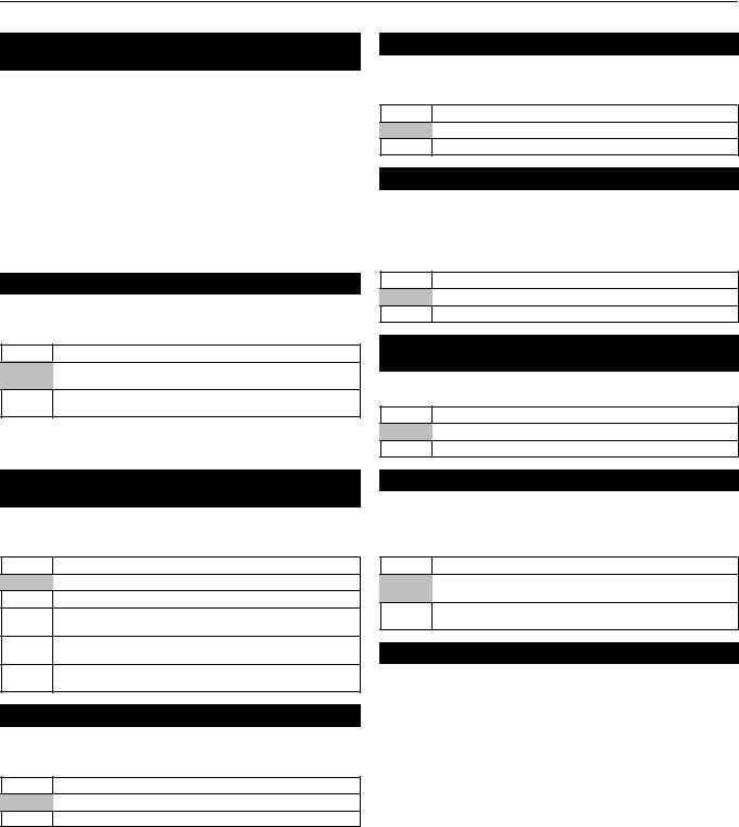
Operation Mode Selection (n02)
Select the method of operation mode input to start or stop the Inverter in remote mode.
Value |
Description |
0The RUN and STOP/RESET Keys of the Digital Operator are enabled.
1Multi-function input in 2- or 3-wire sequence through the control circuit terminals is enabled.
Note: In local mode, RUN commands can be entered using the Digital Operator only.
Frequency Reference Selection (n03)
(Remote Mode)
Select the method for inputting the frequency reference to the Inverter in remote mode.
Value |
Description |
0The FREQ adjuster of the Digital Operator is enabled.
1Frequency reference 1 (n21) is enabled.
2The frequency reference control terminal (for 0- to 10-V input) is enabled.
3The frequency reference control terminal (for 4- to 20-mA current input) is enabled.
4The frequency reference control terminal (for 0- to 20-mA current input) is enabled.
Interruption Mode Selection (n04)
Select the stopping method to be used when the STOP command is input.
Value |
Description |
0Frequency deceleration stop (Decelerates to stop in preset time.)
1Free running (Output shut OFF by STOP command.)
Reverse Rotation-prohibit Selection (n05)
Select the operation to be performed when the reverse rotation command is input.
Value |
Description |
0Reverse rotation possible (command accepted)
1Reverse rotation prohibited (command not accepted)
STOP/RESET Key Function Selection (n06)
When parameter n02 is set to 1, set whether or not to use the STOP/RESET Key of the Digital Operator to stop the Inverter in remote mode. The STOP/RESET Key is always enabled in local mode regardless of the setting in n02.
Value |
Description |
0The STOP/RESET Key of the Digital Operator is enabled.
1The STOP/RESET Key of the Digital Operator is disabled.
Frequency Reference Selection (n07)
(Local Mode)
Select the input method of frequency references in local mode.
Value |
Description |
0The FREQ adjuster of the Digital Operator is enabled.
1Key sequences on the Digital Operator are enabled.
Key Sequential Frequency Setting (n08)
Select whether to enable the Enter Key when setting the frequency reference with the Increment and Decrement Keys on the Digital Operator.
Value |
Description |
0The Enter Key is enabled. (The setting is made valid by pressing the Enter Key.)
1The Enter Key is disabled. (The setting is directly treated as a frequency reference without the Enter Key being pressed.)
V/f Pattern Settings (n09 to n15)
Set the V/f pattern as the basic characteristic of the Inverter with output voltage per frequency set.
Value |
Name |
Setting |
Unit of |
Default |
|
|
range |
setting |
settings |
|
|
|
|
|
n09 |
Maximum Frequency |
50.0 to 400 |
0.1 Hz |
60.0 |
|
(FMAX) |
|
|
|
|
|
|
|
|
n10 |
Maximum Voltage (VMAX) |
1 to 255 |
1 V |
200 |
|
|
|
|
|
n11 |
Maximum Voltage |
0.2 to 400 |
0.1 Hz |
60.0 |
|
Frequency (FA) |
|
|
|
|
|
|
|
|
n12 |
Middle Output Frequency |
0.1 to 399 |
0.1 Hz |
1.5 |
|
(FB) |
|
|
|
|
|
|
|
|
n13 |
Middle Output Frequency |
1 to 255 |
1 V |
12 |
|
Voltage (VC) |
|
|
|
|
|
|
|
|
n14 |
Minimum Output |
0.1 to 10.0 |
0.1 Hz |
1.5 |
|
Frequency (FMIN) |
|
|
|
|
|
|
|
|
n15 |
Minimum Output |
1 to 50 |
1 V |
12 |
|
Frequency Voltage (VMIN) |
|
|
|
14

Function of Each Parameter
Note: For n09, n11, and n12, the unit of setting is as follows: Values will be set in 0.1-Hz increments if the frequency is less than 100 Hz and 1-Hz increments if the frequency is 100 Hz or greater.
Output voltage (V)
n10
n13
n15
Frequency
(Hz)
Note: 1. Set the parameters so that the following condition will be satisfied.
n14 x n12 < n11 x n09
2.The value set in n13 will be ignored if parameters n14 and n12 are the same in value.
Acceleration/Deceleration Time Settings (n16 to n19)
The acceleration time is the time required to go from 0% to 100% of the maximum frequency and the deceleration time is the time required to go from 100% to 0% of the maximum frequency. The actual acceleration or deceleration time is obtained from the following formula.
Acceleration/Deceleration time =
(Acceleration/Deceleration time set value) × (Frequency reference value) ÷ (Max. frequency)
Value |
Name |
Setting |
Unit of |
Default |
|
|
range |
setting |
set- |
|
|
|
|
tings |
|
|
|
|
|
n16 |
Acceleration time 1 |
0.0 to 999 |
0.1 s |
10.0 |
|
|
|
|
|
n17 |
Deceleration Time 1 |
|
|
10.0 |
|
|
|
|
|
n18 |
Acceleration time 2 |
|
|
10.0 |
|
|
|
|
|
n19 |
Deceleration Time 2 |
|
|
10.0 |
|
|
|
|
|
S-shape Acceleration/Deceleration Characteristic (n20)
Any one of three S-shape acceleration/deceleration times (0.2, 0.5, and 1.0 s) is selectable.
Value |
Description |
|
|
0 |
No S-shape acceleration/deceleration characteristic |
|
(Trapezoidal acceleration/deceleration) |
1 |
S-shape acceleration/deceleration characteristic time is 0.2 s |
|
|
2 |
S-shape acceleration/deceleration characteristic time is 0.5 s |
|
|
3 |
S-shape acceleration/deceleration characteristic time is 1.0 s |
Note: When the S-shape acceleration/deceleration characteristic time is set, the acceleration and deceleration times will be lengthened according to the S-shape at the beginning and end of acceleration/deceleration.
Setting the Frequency References 1 to 8 and the Inching Frequency Command (n21 to n28 and n29)
Set internal frequency references.
Value |
Name |
Setting |
Unit of |
Default |
|
|
|
range |
setting |
set- |
|
|
|
|
|
tings |
|
|
|
|
|
|
|
n21 |
Frequency reference 1 |
0.0 to max. |
0.1 Hz |
6.0 |
|
|
|
frequency |
(see note |
|
|
n22 |
Frequency reference 2 |
0.0 |
|||
|
1) |
||||
|
|
|
|
||
n23 |
Frequency reference 3 |
|
0.0 |
||
|
|
||||
|
|
|
|
|
|
n24 |
Frequency reference 4 |
|
|
0.0 |
|
|
|
|
|
|
|
n25 |
Frequency reference 5 |
|
|
0.0 |
|
|
|
|
|
|
|
n26 |
Frequency reference 6 |
|
|
0.0 |
|
|
|
|
|
|
|
n27 |
Frequency reference 7 |
|
|
0.0 |
|
|
|
|
|
|
|
n28 |
Frequency reference 8 |
|
|
0.0 |
|
|
|
|
|
|
|
n29 |
Inching frequency com- |
|
|
6.0 |
|
|
mand |
|
|
|
Note: 1. Values will be set in 0.1-Hz increments if the frequency is less than 100 Hz and 1-Hz increments if the frequency is 100 Hz or over.
2.Frequency reference 1 is enabled with n03 for frequency reference selection set to 1. (Remote mode)
3.Frequency references 1 to 8 are enabled by setting multistep speed references 1, 2, and 3 in n36 to n39 for multi-func- tion input. Refer to the following table for the relationship between multi-step speed references 1 to 3 and frequency references 1 to 8.
Frequency |
Multi-step speed |
Multi-step speed |
Multi-step speed |
reference |
reference 1 |
reference 2 |
reference 3 |
|
|
|
|
Frequency |
OFF |
OFF |
OFF |
reference 1 |
|
|
|
|
|
|
|
Frequency |
ON |
OFF |
OFF |
reference 2 |
|
|
|
|
|
|
|
Frequency |
OFF |
ON |
OFF |
reference 3 |
|
|
|
|
|
|
|
Frequency |
ON |
ON |
OFF |
reference 4 |
|
|
|
|
|
|
|
Frequency |
OFF |
OFF |
ON |
reference 5 |
|
|
|
|
|
|
|
Frequency |
ON |
OFF |
ON |
reference 6 |
|
|
|
|
|
|
|
Frequency |
OFF |
ON |
ON |
reference 7 |
|
|
|
|
|
|
|
Frequency |
ON |
ON |
ON |
reference 8 |
|
|
|
Note: 1. “ON” and “OFF” represent “input ON” and “input OFF,” respectively.
2.Inching frequency commands take precedence over multistep speed references.
15
Function of Each Parameter
Frequency Reference Upper and Lower Limit
Settings (n30 and n31)
Set the upper and lower frequency reference limits in percentage based on the maximum frequency as 100%.
Value |
Name |
Setting |
Unit of |
Default |
|
|
range |
setting |
settings |
|
|
|
|
|
n30 |
Frequency Reference |
0 to 110 |
1% |
100 |
|
Upper Limit |
|
|
|
|
|
|
|
|
n31 |
Frequency Reference |
0 to 110 |
1% |
0 |
|
Lower Limit |
|
|
|
Note: If n31 is set to a value less than the minimum output frequency (FMIN) (n14), the Inverter will have no output when a frequency reference less than the minimum output frequency input is ON.
Rated Motor Current Setting (n32)
Set the rated motor current as the reference value for motor overload detection (OL1).
Note: 1. Setting 0.0 disables the motor overload detection (OL1) function.
2.The rated motor current value is factory-set for each Inverter according to the maximum applicable motor capacity.
Value |
Name |
Setting range |
Unit of |
Default |
|
|
|
setting |
settings |
|
|
|
|
|
n32 |
Rated Motor Current |
0.0% to 120% (A) of |
0.1 A |
Varies with |
|
|
rated output current |
|
the capac- |
|
|
of Inverter |
|
ity. |
Motor Protection Characteristic Selection (n33)
Set the motor overload detection (OL1) for the electronic thermal characteristics of the motor.
Value |
Description |
0Protection characteristics for general-purpose induction motors
1Protection characteristics for Inverter-dedicated motors
2No protection
Note: When connecting multiple motors to one Inverter, set 2 (equivalent to n32 = 0.0). In addition, take overload prevention measures by mounting a thermal relay in each motor, for example.
Motor Protective Time Setting (n34)
Set the electronic thermal characteristics of the motor to be connected in 1-minute increments.
Value |
Name |
Setting |
Unit of |
Default |
|
|
range |
setting |
settings |
|
|
|
|
|
n34 |
Motor Protective Time |
1 to 60 |
1 min |
8 |
|
Setting |
|
|
|
Note: 1. The default setting does not need any changes in normal operation.
2.To set the parameter according to the characteristics of the motor, confirm the thermal time constant with the motor manufacturer and set the parameter with some margin. In other words, set the value a little shorter than the thermal time constant.
3.To detect motor overloading more quickly, reduce the set value, provided that it does not cause any application problems.
Cooling Fan Operation Function Selection (n35)
This parameter is used to operate the cooling fan of the Inverter while the Inverter is turned on or only while the Inverter is in operation.
Value |
Description |
0The fan rotates only while the RUN command is input and for 1 minute after the Inverter stops operating.
1The fan rotates while the Inverter is turned ON.
Note: 1. This parameter is available only if the Inverter incorporates a cooling fan.
2.If the operation frequency of the Inverter is low, the life of the fan can be prolonged by setting the parameter to 0.
Multi-function Input Selection (n36 to n39)
Select the functions of multi-function input terminals S2 to S5.
Value |
Name |
Setting |
Unit of |
Default |
|
|
range |
setting |
settings |
|
|
|
|
|
n36 |
Multi-function Input 1 |
2 to 8, 10 to |
1 |
2 |
|
(S2) |
22 |
|
|
|
|
|
|
|
n37 |
Multi-function Input 2 |
0, 2 to 8, 10 |
1 |
5 |
|
(S3) |
to 22 |
|
|
|
|
|
|
|
n38 |
Multi-function Input 3 |
2 to 8, 10 to |
1 |
3 |
|
(S4) |
22 |
|
|
|
|
|
|
|
n39 |
Multi-function Input 4 |
2 to 8, 10 to |
1 |
6 |
|
(S5) |
22, 34 |
|
|
Value |
Function |
|
Description |
|
|
|
|
0 |
Forward/Reverse |
3-wire sequence (to be set in n37 only) |
|
|
rotation command |
This setting overrides the n36 setting. |
|
|
|
||
|
|
S1: |
RUN input (RUN when ON) |
|
|
S2: |
STOP input |
|
|
|
(STOP when OFF) |
|
|
S3: |
Forward/Reverse rotation |
|
|
|
command |
|
|
|
(ON: Reverse) |
|
|
|
|
2 |
Reverse/Stop |
Reverse rotation command (2-wire |
|
|
|
sequence) (ON: Reverse) |
|
|
|
|
|
3 |
External fault (NO) |
ON: External fault |
|
|
|
|
|
4 |
External fault (NC) |
OFF: External fault |
|
|
|
|
|
5 |
Fault reset |
ON: Fault reset |
|
|
|
Note |
Disabled while RUN command is |
|
|
|
input |
|
|
|
|
6 |
Multi-step speed |
Signals to select frequency references 1 to |
|
|
reference 1 |
8. |
|
|
|
|
|
7 |
Multi-step speed |
|
|
|
reference 2 |
|
|
|
|
|
|
8 |
Multi-step speed |
|
|
|
reference 3 |
|
|
|
|
|
|
10 |
Inching frequency |
ON: Inching frequency command |
|
|
command |
|
|
|
|
|
|
11 |
Acceleration/Decel- |
ON: Acceleration/deceleration time 2 |
|
|
eration time selec- |
|
|
|
tion |
|
|
|
|
|
|
12 |
External base block |
ON: Output shut OFF (while motor coasting |
|
|
command (NO) |
to a stop and “bb” flashing) |
|
|
|
|
|
13 |
External base block |
OFF: Output shut OFF (with motor free |
|
|
command (NC) |
running and “bb” flashing) |
|
|
|
|
|
14 |
Search command |
ON: Speed search (Searching starts from |
|
|
(Searching starts |
n09) |
|
|
from maximum fre- |
|
|
|
quency) |
|
|
|
|
|
|
16
Function of Each Parameter
Value |
Function |
|
Description |
|
|
|
|
||
15 |
Search command |
ON: Speed search (Searching starts from |
||
|
(Searching starts |
the frequency specified by n03.) |
||
|
from preset frequen- |
|
|
|
|
cy) |
|
|
|
|
|
|
||
16 |
Acceleration/Decel- |
ON: Acceleration/Deceleration is on hold |
||
|
eration-prohibit com- |
|
|
|
|
mand |
|
|
|
|
|
|
||
17 |
Local or remote |
ON: Local mode (operated with the Digital |
||
|
selection |
Operator) |
|
|
|
|
|
||
19 |
Emergency stop |
The Inverter stops according to the setting in |
||
|
fault (NO) |
n04 for interruption mode selection when the |
||
|
|
emergency stop input turns ON. |
||
|
|
Note |
NO: Emergency stop with the con- |
|
20 |
Emergency stop |
|||
|
tact closed. |
|||
|
alarm (NO) |
|
||
|
|
NC: Emergency stop with the con- |
||
|
|
|
||
|
|
|
tact opened. |
|
21 |
Emergency stop |
Note |
Fault: Fault output is ON and reset |
|
|
fault (NC) |
|||
|
|
with RESET input. Alarm output is |
||
|
|
|
||
|
|
|
ON (no reset required). |
|
22 |
Emergency stop |
Note |
“STP” is displayed (lit with fault in- |
|
|
alarm (NC) |
|
put ON and flashes with alarm in- |
|
|
|
|
||
|
|
|
put ON) |
|
|
|
|
||
34 |
Up or down com- |
Up or down command (set in n39 only) |
||
|
mand |
This setting overrides the n38 setting. |
||
|
|
|||
|
|
S4: Up command |
||
|
|
S5: Down command |
||
|
|
|
|
|
Multi-function Output Selection (n40)
Select the functions of multi-function output terminals.
Value |
Name |
|
|
|
Setting |
|
Unit of |
|
Default |
|
|
|
|
|
|
|
range |
|
setting |
|
set- |
|
|
|
|
|
|
|
|
|
|
tings |
|
|
|
|
|
|
|
|
|
|
|
n40 |
Multi-function Output (MA/ |
|
0 to 7, 10 to |
|
1 |
|
1 |
|||
|
|
MB and MC) |
|
|
|
17 |
|
|
|
|
|
|
|
|
|
|
|
|
|||
Value |
|
Function |
|
|
|
Description |
|
|||
|
|
|
|
|
|
|
||||
0 |
|
Fault output |
ON: Fault output |
|
|
|
||||
|
|
|
|
|
|
|
||||
1 |
|
Operation in |
ON: Operation in progress |
|
|
|
||||
|
|
progress |
|
|
|
|
|
|
|
|
|
|
|
|
|
|
|
||||
2 |
|
Frequency |
ON: Frequency detection |
|
|
|
||||
|
|
detection |
|
|
|
|
|
|
|
|
|
|
|
|
|
|
|
|
|
||
3 |
|
Idling |
ON: Idling |
|
|
|
|
|
||
|
|
|
|
|||||||
4 |
|
Frequency |
ON: Output frequency y frequency detection |
|||||||
|
|
detection 1 |
level (n58) |
|
|
|
|
|
||
|
|
|
|
|||||||
5 |
|
Frequency |
ON: Output frequency x frequency detection |
|||||||
|
|
detection 2 |
level (n58) |
|
|
|
|
|
||
|
|
|
|
|
||||||
6 |
|
Overtorque |
Output if any of the following parameter |
|
||||||
|
|
being monitored |
conditions is satisfied. |
|
|
|
||||
|
|
(NO-contact |
• |
Overtorque detection function selection (n59) |
||||||
|
|
output) |
||||||||
|
|
• |
|
|
|
|
|
|
|
|
|
|
|
Overtorque detection level (n60) |
|
||||||
7 |
|
Overtorque |
• |
Overtorque detection time (n61) |
|
|||||
|
|
being monitored |
Note |
NO contact: ON with overtorque be- |
||||||
|
|
(NC-contact |
||||||||
|
|
|
|
|
ing detected; NC contact: OFF with |
|||||
|
|
output) |
|
|
|
|||||
|
|
|
|
|
|
overtorque being detected |
|
|||
|
|
|
|
|
|
|
|
|
|
|
8 |
|
(Not used) |
--- |
|
|
|
|
|
|
|
|
|
|
|
|
|
|
|
|
|
|
9 |
|
|
|
|
|
|
|
|
|
|
|
|
|
|
|||||||
10 |
|
Alarm output |
ON: Alarm being detected (Nonfatal error) |
|||||||
|
|
|
|
|
|
|
||||
11 |
|
Base block in |
ON: Base block in progress |
|
|
|
||||
|
|
progress |
|
|
|
|
|
|
|
|
|
|
|
|
|
|
|
||||
12 |
|
RUN mode |
ON: Local mode |
|
|
|
||||
|
|
|
|
|
||||||
13 |
|
Inverter ready |
ON: Inverter ready to operate |
|
||||||
|
|
|
|
|
|
|
||||
14 |
|
Fault retry |
ON: Fault retry |
|
|
|
||||
|
|
|
|
|
|
|
|
|||
Value |
|
Function |
|
|
|
Description |
|
|||
15 |
UV in progress |
ON: Undervoltage being monitored (main circuit |
|
|
undervoltage UV or UV1 detected) |
|
|
|
16 |
Rotating in |
ON: Rotating in reverse direction |
|
reverse |
|
|
direction |
|
|
|
|
17 |
Speed search |
ON: Speed search in progress |
|
in progress |
|
Note: Use “operation in progress” or “frequency detection 1/2” for the timing of the external brake.
Gain and Bias Settings (n41 and n42)
Set the input characteristics of analog frequency references in n41 (for the frequency reference gain) and n42 (for the frequency reference bias).
Set the frequency of maximum analog input (10 V or 20 mA) in n41 as percentage based on the maximum frequency as 100%.
Set the frequency of minimum analog input (0 V, 0 mA, or 4 mA) in n42 as percentage based on the maximum frequency as 100%.
Value |
Name |
Setting |
Unit of |
Default |
|
|
range |
setting |
settings |
|
|
|
|
|
n41 |
Frequency Reference |
0 to 255 |
1% |
100 |
|
Gain |
|
|
|
|
|
|
|
|
n42 |
Frequency Reference |
–99 to 99 |
1% |
0 |
|
Bias |
|
|
|
Analog Frequency Reference Filter Time Setting (n43)
The digital filter with a first-order lag can be set for analog frequency references to be input.
Value |
Name |
Setting |
Unit of |
Default |
|
|
range |
setting |
settings |
|
|
|
|
|
n43 |
Analog Frequency Refer- |
0.00 to 2.00 |
0.01 s |
0.10 |
|
ence Filter Time |
|
|
|
Analog Monitor Output Setting (n44)
Set a monitored item for analog monitor output.
Value |
Description |
0Output frequency (Reference: 10 V at max. frequency)
1Output current (Reference: 10 V with rated output current)
Note: The values in parentheses are applicable when n45 is set to 1.00.
Analog Monitor Output Gain Setting (n45)
Set the output characteristics of analog monitor output.
Value |
Name |
Setting |
Unit of |
Default |
|
|
range |
setting |
settings |
|
|
|
|
|
n45 |
Analog Monitor Output |
0.00 to 2.00 |
0.01 |
1.00 |
|
Gain |
|
|
|
17
 Loading...