


Service Manual for L1 and L2
Nokia Lumia 920
RM-820, RM-821
Key features
zWindows Phone 8
z1.5 GHz dual-core processor (Qualcomm Snapdragon S4)
z32 GB internal flash memory
zEGSM, WCDMA HSPA and 4G LTE
zNear Field Communication (NFC) technology
zWireless charging (Qi standard)
Version 1.0
Check the repair policy before performing any mechanical repair on Service Level 1&2!
Exploded view |
Disassembly steps |
Disassembly video |
|
More |
More |
More |
Assembly steps |
Assembly video |
|
Solder components |
More |
More |
Service devices |
Product controls and interfaces Service concept |
More |
More |
More |
Phone reset
More
©2012 Nokia | Nokia Internal Use only | All Rights Reserved.

Service Manual Level 1 and 2
Nokia Lumia 920
RM-820, RM-821
Version 1.0
Exploded view
DISPLAY MODULE ASSEMBLY
(I0003 - I0005)
|
A-COVER |
WINDOW ASSEMBLY |
|
I0003 |
|
|
I0005 |
|
|
|
|
|
|
DISPLAY |
|
|
I0004 |
|
|
|
|
SIM DOOR |
|
|
I0001 |
|
|
SCREW TORX+ SIZE 4 |
SCREW TORX+ SIZE 5 |
|
M1.4 x 3.0 |
|
|
M2.5 X 9.7 |
|
|
I0016 |
|
|
I0002 |
|
|
CAMERA |
|
|
|
|
|
I0019 |
CAMERA |
|
|
|
|
CAMERA BOOT |
CONNECTOR SUPPORT |
2 |
I0018 |
I0020 |
LIGHT SWAP PACKAGE |
|
|
(I0006 - I0008) |
|
|
|
LIGHT SWAP PWB |
MAIN FLEX |
|
I0006 |
|
|
I0007 |
|
|
|
3CHASSIS ASSEMBLY
(I0023 - I0026)
* Will be part of the A3 CHASSIS ASSEMBLY
EJECTING ARM CUSHION I0023
EARPIECE
I0021
USB CONNECTOR SUPPORT
I0011 TYPE LABEL
I0008
TYPE LABEL SUPPORT I0017 SCREW TORX+
SIZE 2 MG1.2 x 2.6 I0015 CONNECTOR HOLDING TAPE I0010
BATTERY CONNECTOR FIXING TAPE I0009
6 |
AV FLEX ASSEMBLY |
||
(I0040 - I0042) |
|
||
2ND MICROPHONE |
|||
|
|
I0041 |
|
|
AV JACK |
||
|
|
I0042 |
|
|
AV FRAME |
||
|
|
I0040 |
|
|
USB FLEX SUPPORT |
||
* Will be part of the |
I0038 |
||
I0037 MAIN ANTENNA |
|||
|
HEAT SPREADER |
||
* Will be part of the |
I0028 |
||
A4 UNIBODY ASSEMBLY |
|||
|
AV DECO ADHESIVE |
||
|
|
I0031 |
|
|
VOLUME KEY |
||
|
|
I0029 |
|
|
LED FLASH |
||
|
|
I0032 |
|
|
CAMERA DECO |
||
v1.0 |
|||
|
I0033 |
||
|
|
|
|
IHF SPEAKER
I0024
SPEAKER GASKET
I0025
CHASSIS
I0026
EARPIECE GASKET
I0022
BATTERY SUPPORT
I0013
BATTERY HOLDER
I0012
SCREW TORX+
SIZE 4 M1.4 X 3.0
I0016
ANTENNA COAX CABLE
I0027
BATTERY BP-4GW
I0014
|
USB ASSEMBLY |
5 |
|
|
(I0035 - I0036) |
||
|
MICRO USB CONNECTOR |
|
|
|
I0035 |
|
|
|
MICROPHONE |
|
|
|
I0036 |
|
|
|
MAIN ANTENNA |
|
|
|
I0037 |
|
|
|
WPC RX MODULE |
|
|
|
I0039 |
|
4 |
|
UNIBODY ASSEMBLY |
||
|
(I0028 - I0034) |
||
|
CAPTURE KEY |
|
|
|
I0030 |
|
|
|
CAMERA WINDOW |
|
|
|
I0034 |
|
|
Only available |
Not reuseable |
Repair/swap |
|
as assembly |
after removal |
only in level 3 |
|
©2012 Nokia | Nokia Internal Use only | All Rights Reserved.
Service Manual Level 1 and 2
Nokia Lumia 920
RM-820, RM-821
Version 1.0
Disassembly steps
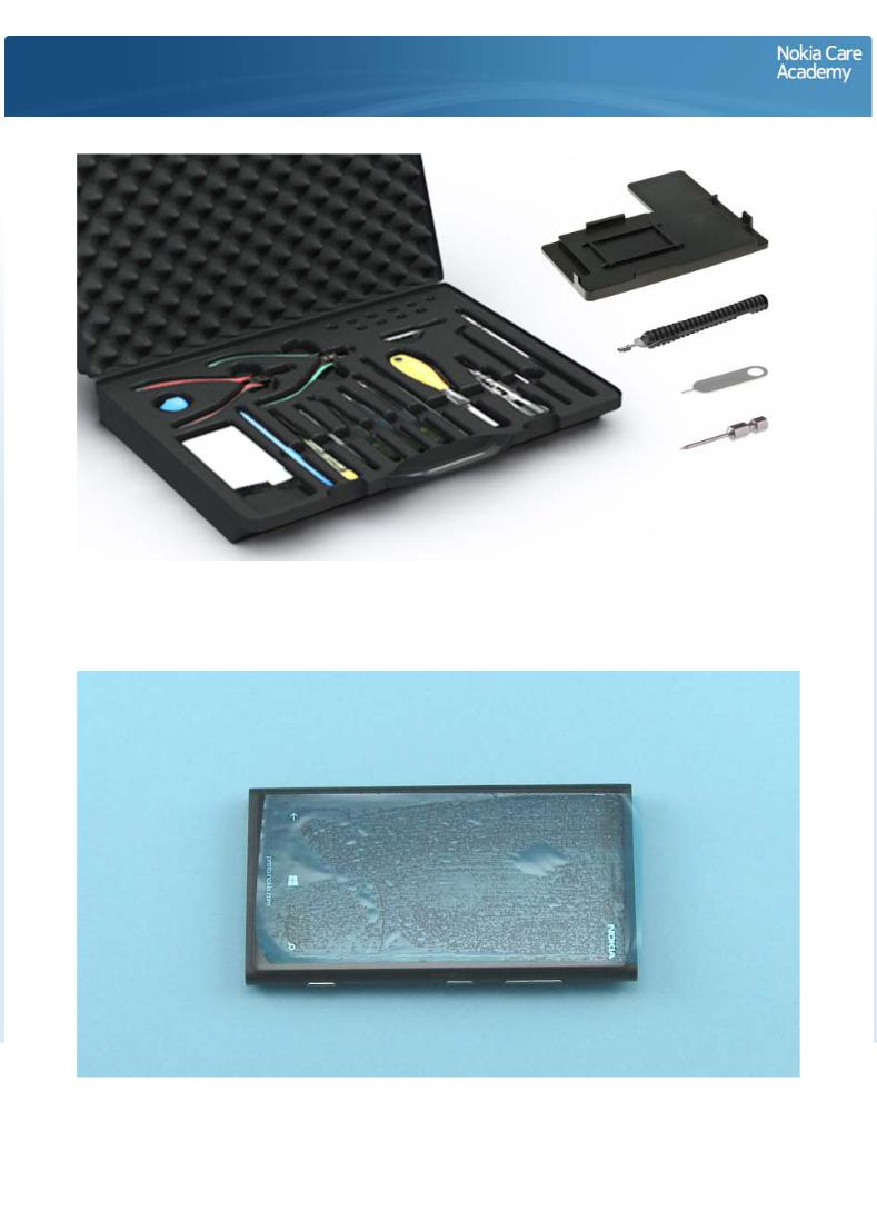
For disassembling you need the Nokia Standard Tool kit version 2. You will also need the SIM door key, the RF connector disassembly/assembly tool SS-231, the SS-299 screwdriver and the Care chassis assembly jig SS-289.
Protect the TOUCH SCREEN with protective film.
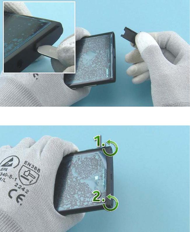
Release the SIM DOOR with the SIM door key and remove it.
Unscrew the two TORX+ size 5 screws from the bottom of the device in the order shown.
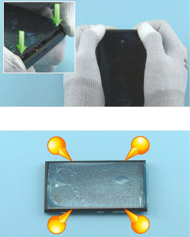
Push from the bottom corners of the UNIBODY ASSEMBLY so that the DISPLAY MODULE ASSEMBLY comes out of the UNIBODY ASSEMBLY.
There are differecies in material tightness between color variants. If the UNIBODY ASSEMBLY sides are hard to remove with fingers, use SRT-6 to release the sides to avoid scratches in the UNIBODY ASSEMBLY.
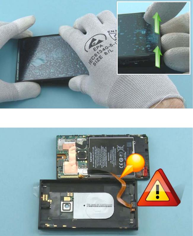
Lift the DISPLAY MODULE ASSEMBLY out of the UNIBODY ASSEMBLY bottom end first.
Turn the DISPLAY MODULE ASSEMBLY so that the ENGINE BOARD side is facing up and place it next to the UNIBODY ASSEMBLY. Be careful not to bend the USB flex.
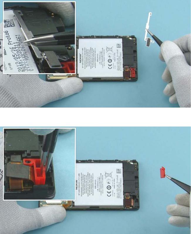
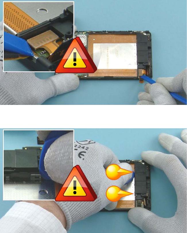
Remove the BATTERY CONNECTOR FIXING TAPE with tweezers. Do not use it again. Discard it.
If the device has the CONNECTOR HOLDING TAPE assembled, remove it with tweezers. Do not use it again. Discard it.
Open the BATTERY connector with the SRT-6. Be careful not to damage the connector or any components nearby.
Release the USB CONNECTOR SUPPORT from the left side with the sharp end of the SS-93.
Remove the USB CONNECTOR SUPPORT by lifting it up with tweezers. Be careful not to insert the tweezers under the connectors located beneath the USB CONNECTOR SUPPORT. The USB CONNECTOR SUPPORT is not reusable. Discard it.
Open the USB flex connector with the SRT-6. Be careful not to damage the connector or any components nearby.
The UNIBODY ASSEMBLY can now be removed.
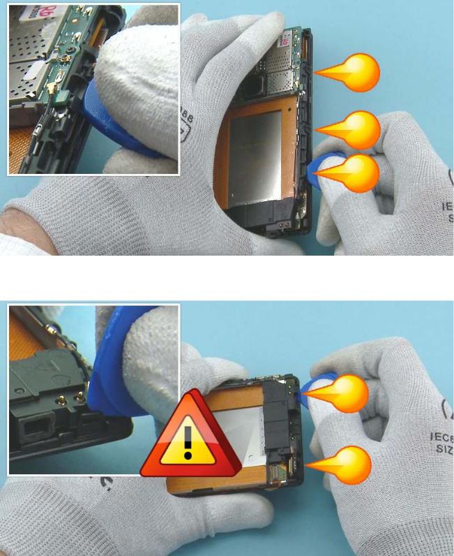
Open the side key connector with the SRT-6. Be careful not to damage the connector or any components nearby.
Unscrew the TORX+ size 4 screw. Do not use it again. Discard it.
Release the BATTERY HOLDER with the SS-93.
Remove the BATTERY HOLDER with tweezers.
Remove the BATTERY SUPPORT with tweezers.
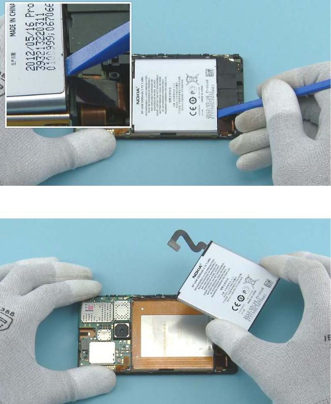
Lift up the BATTERY from the bottom end with the SS-93.
Remove the BATTERY.
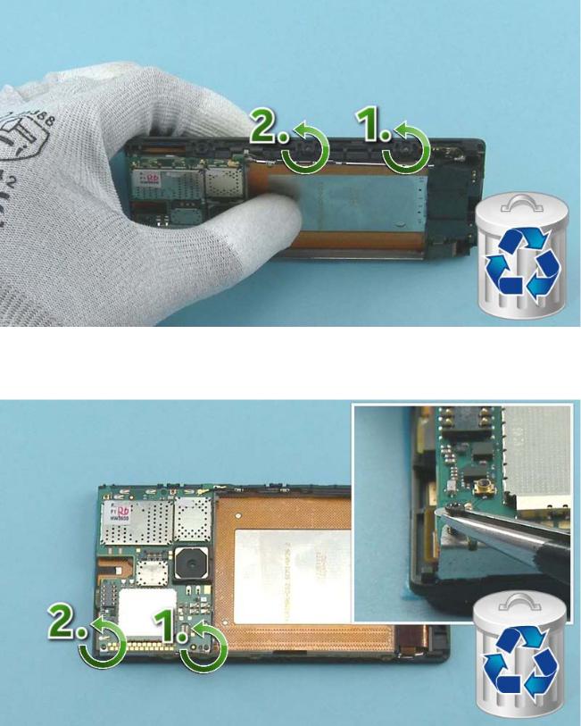
Unscrew the two TORX+ size 4 screws on the shown side of the CHASSIS in the order shown. Do not use them again. Discard them.
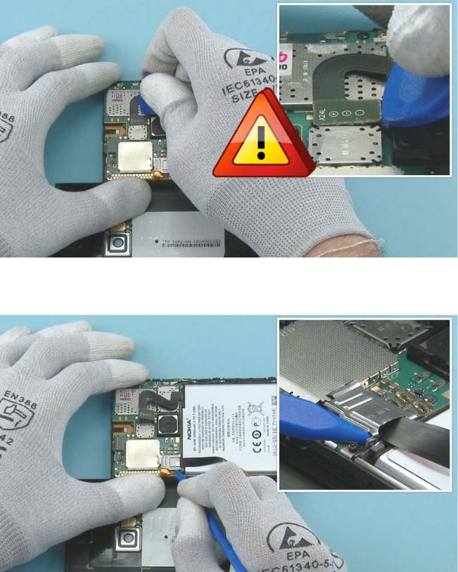
Unscrew the two TORX+ size 2 screws with the SS-299 screwdriver in the order shown. Use tweezers to remove the screw to avoid bending the springs on the ENGINE BOARD. Do not use the screws again. Discard them.
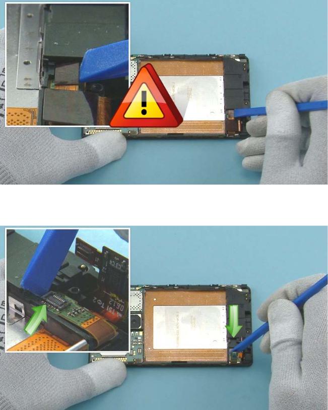
Open the touch connector with the SS-93. Be careful not to damage the connector or any components nearby.
Slide the touch connector out of the CHASSIS as shown with the SS-93.
Open the DISPLAY connector with the SS-93. Be careful not to damage the connector or any components nearby.
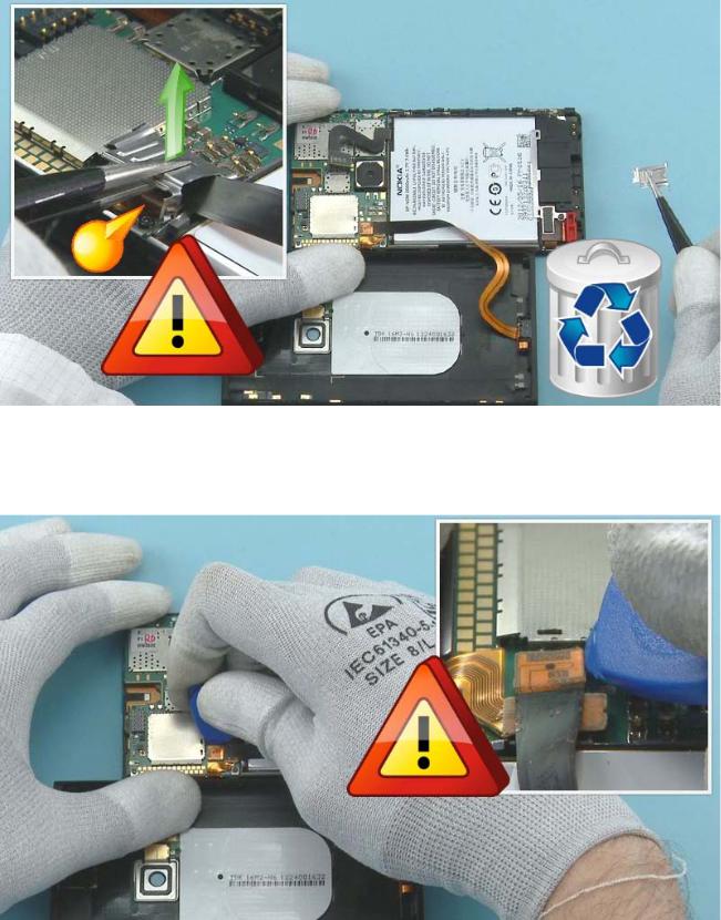
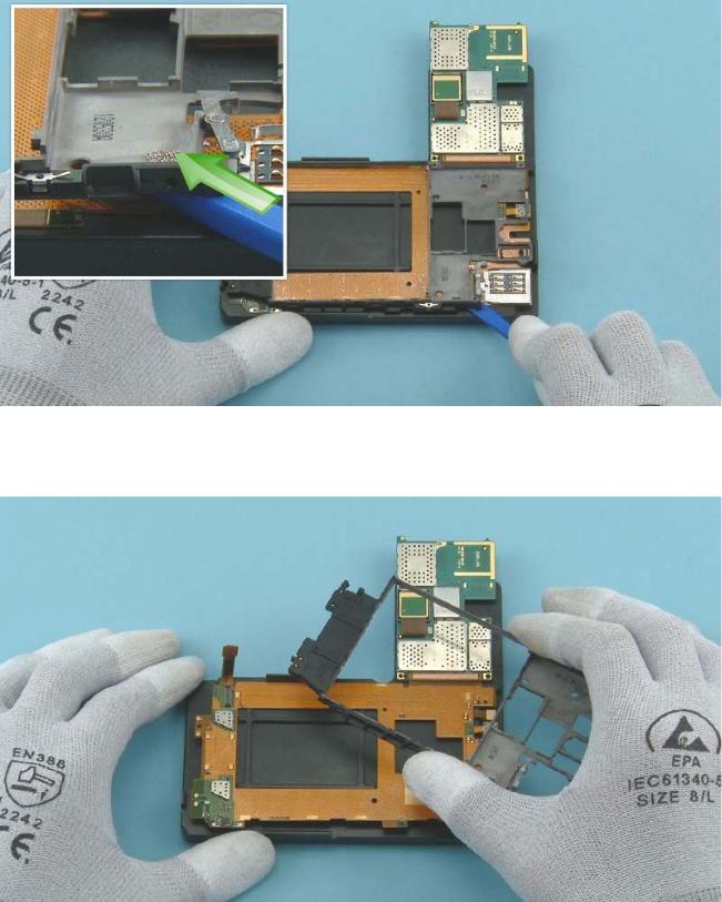
To release the CHASSIS first open the two clips at the bottom of the battery compartment with the SRT- 6. Be careful not to bend the clips too much.
Then release the clips from the shown side of the CHASSIS starting from the top.
Then open the two clips at the bottom end starting from the shown side. Be careful not to break the clips.

Lift up the CHASSIS including the ENGINE BOARD from the shown side.
Remove the CHASSIS including the ENGINE BOARD.
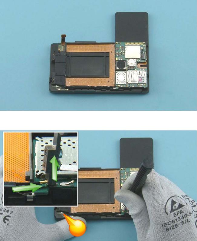
Place the CHASSIS including the ENGINE BOARD on the Care chassis assembly jig.
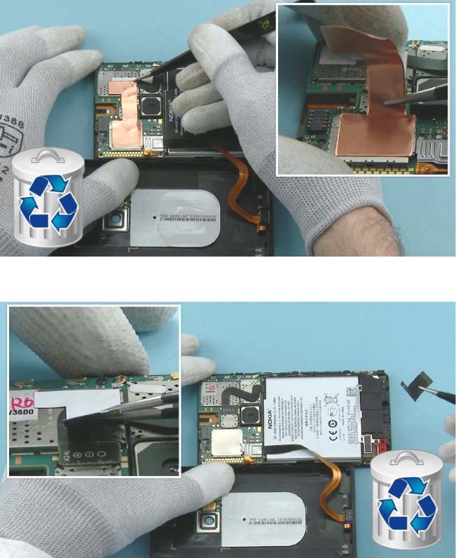
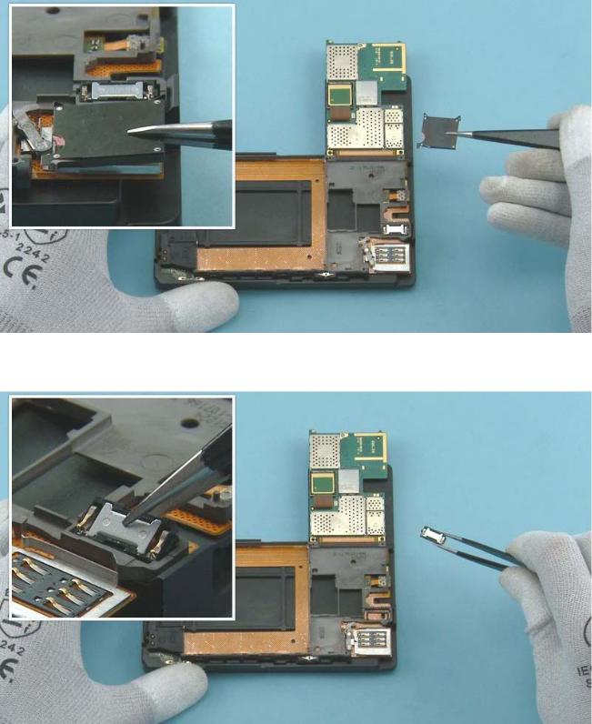
Open the ANTENNA COAX CABLE connector from the main ENGINE BOARD side with the SS-231. Lock the SS-231 to the top of the connector as shown and lift it up carefully. Keep the other end of the ANTENNA COAX CABLE connected.
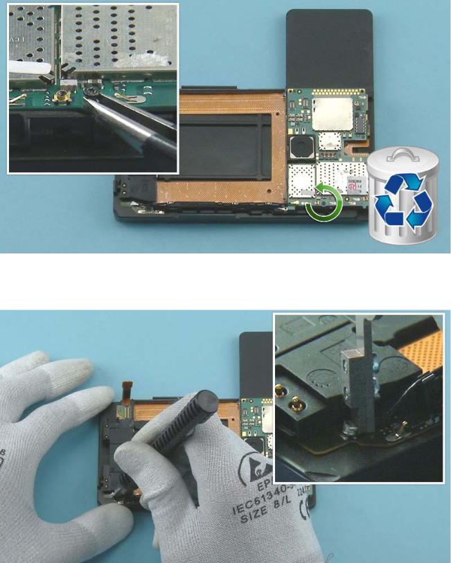
Unscrew the TORX+ size 2 screw with the SS-299 screwdriver. Use tweezers to remove the screw to avoid bending the springs on the ENGINE BOARD. Do not use the screw again. Discard it.
Open the ANTENNA COAX CABLE connector from the bottom end with the SS-231.
Remove the ANTENNA COAX CABLE by lifting it from the metal sheets with tweezers.
Turn over the ENGINE BOARD as shown.
Remove the TYPE LABEL SUPPORT with tweezers.
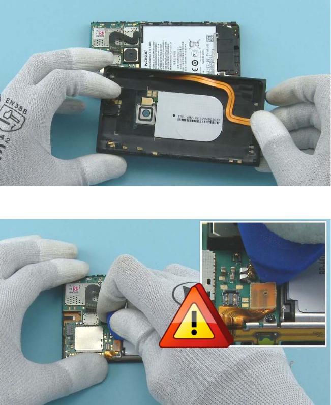
Remove the EARPIECE with tweezers.
Release the adhesive holding the CHASSIS and the MAIN FLEX together by sliding the SS-93 under the CHASSIS.
Remove the CHASSIS.
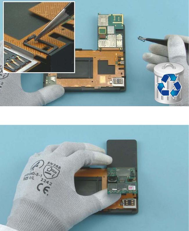
Remove the EARPIECE GASKET with tweezers. Do not use it again. Discard it.
Turn the ENGINE BOARD over and hold it as shown.

Gently PUSH the CAMERA through the CAMERA BOOT with the SS-93.
Turn over the ENGINE BOARD and open the CAMERA connector with the SS-93. Be careful not to damage the connector or any components nearby.
 Loading...