


G241W A

Alcatel-Lucent 7368 ISAM ONT 1-1
Edition 01
I-240W-S I-241W-S I-241W-U Product Guide
1 — G-241W-A unit data sheet
1.1 G-241W-A part numbers and identification 1-2
1.2 G-241W-A general description 1-3
1.3 G-241W-A software and installation feature support 1-4
1.4 G-241W-A interfaces and interface capacity 1-4
1.5 G-241W-A LEDs 1-6
1.6 G-241W-A detailed specifications 1-8
1.7 G-241W-A GEM ports and T-CONTs 1-9
1.8 G-241W-A performance monitoring statistics 1-9
1.9 G-241W-A functional blocks 1-11
1.10 G-241W-A standards compliance 1-14
1.11 G-241W-A special considerations 1-14

1 — G-241W-A unit data sheet
1-2 Alcatel-Lucent 7368 ISAM ONT
Edition 01
I-240W-S I-241W-S I-241W-U Product Guide
1.1 G-241W-A part numbers and identification
Table 1-1 provides part numbers and identification information for G-241W-A
indoor ONTs.
Table 1-1 G-241W-A indoor ONT part numbers and identification
The G-241W-A ONT uses a fiber storage tray that can be ordered separately. The
part number for the fiber tray is 3FE 71441 AA.
Table 1-2 lists ONT to UPS or power adapter support mapping, including the
specifications and standards tested to.
Mnemonic Ordering kit
part number
Provisioning
part number
Description CLEI CPR ECI/
Bar
code
G-241W-A 3FE 56867 AA
customer-
specific
3FE 56977 AA Package D 2 POTS ports, 4 Gig-E
10/100/1000 Base-T interfaces, 1 RF
video connector, and 1 Wi-Fi radio
on/off switch. Includes ac/dc power
cord with European (EU) variant plug.
———
3FE 56867 BA 3FE 56977 BA Package D 2 POTS ports, 4 Gig-E
10/100/1000 Base-T interfaces, 1 RF
video connector, and 1 Wi-Fi radio
on/off switch. Includes ac/dc power
cord with European (EU) variant plug.
———
3FE 56867 BB
customer-
specific
Package D 2 POTS ports, 4 Gig-E
10/100/1000 Base-T interfaces, 1 RF
video connector, and 1 Wi-Fi radio
on/off switch. Includes ac/dc power
cord with European (EU) variant plug.
———
3FE 56867 CA Package D 2 POTS ports, 4 Gig-E
10/100/1000 Base-T interfaces, 1 RF
video connector, and 1 Wi-Fi radio
on/off switch. Includes ac/dc power
cord with United Kingdom (UK) variant
plug.
———
3FE 56867 DA Package D 2 POTS ports, 4 Gig-E
10/100/1000 Base-T interfaces, 1 RF
video connector, and 1 Wi-Fi radio
on/off switch. Includes ac/dc power
cord with United States (US) variant
plug.
———
3FE 56867 DB Package D 2 POTS ports, 4 Gig-E
10/100/1000 Base-T interfaces, 1 RF
video connector, and 1 Wi-Fi radio
on/off switch. Includes ac/dc power
cord with United States (US) variant
plug.
Also includes POTS LED and Molex port
———

1 — G-241W-A unit data sheet
Alcatel-Lucent 7368 ISAM ONT 1-3
Edition 01
I-240W-S I-241W-S I-241W-U Product Guide
Table 1-2 ONT to UPS or power adapter compatibility support
1.2 G-241W-A general description
G-241W-A indoor ONTs provide the subscriber interface for the network by
terminating the PON interface and converting it to user interfaces that directly
connect to subscriber devices. The ONT is compatible with all existing subscriber
equipment, including analog phones with both tone and rotary dial capabilities,
cordless phones, modems, fax machines, and caller ID boxes (Type I, Type II, and
Type III).
G-241W-A indoor ONTs provide the following functions:
• four configurable 10/100/1000BASE-T Ethernet interfaces using RJ-45 ports
• two POTS interfaces using RJ-11 ports
• single mode fiber (SC/APC connector)
• one coaxial RF video connector
• two USB ports
• detachable 3dB/5dB antenna
• IEEE 802.11 b/g/n Wi-Fi interface to enable wireless access
• adjustable Wi-Fi power
• fully G.984 series GPON standard compliant
• G984.5 standard compliant
• compliance with FCC part 15 Class B, CE
• VPN pass-through for PPTP, L2TP, and IPsec
• mapping VLAN to each Ethernet port
• Layer 2 bridging
• NAT/NAPT/port forwarding/DMZ
• IGMP v2/v3
• IPv4 and IPv6
• QoS: CoS or DSCP
• RSSI support
• manual addition of DDNS server
Power/UPS model Power UPS and cabling part
number information
Customer category or
country compliance tested
for
Notes
G-241W-A GPON indoor ONTs
CyberPower
CSN27U12V3
Grounded
(1) 12 V/27 W UPS part number:
3MV00213AA (DC power cord
included)
(2) AC power cord, 1AB38334xxxx:
• 0007 — Australia, New Zealand
• 0008 — Europe
• 0009 — United Kingdom,
Ireland
• 0010 — ANSI
Common European Union
countries
ANSI municipality United
States and Canada
Battery not included.
Compliant battery models:
• BB Battery BP7.2-12
• GS Battery PE 12V7.2
(ANSI GS Battery ALU
part number
1AF17581AC)

1 — G-241W-A unit data sheet
1-4 Alcatel-Lucent 7368 ISAM ONT
Edition 01
I-240W-S I-241W-S I-241W-U Product Guide
TR-069 support for reading optical parameters
The ONT supports the reading of optical parameters via TR-069:
• laser bias current
• voltage
• temperature
• received signal levels
• lower thresholds
These are the same optical parameters supported in the GUI. For more information,
see the chapter “Configure a G-241W-A indoor ONT”.
1.3 G-241W-A software and installation feature support
For information on installing or replacing a G-241W-A, see:
• Install a G-241W-A indoor ONT
• Replace a G-241W-A indoor ONT
For information on the following topics, see the 7368 ISAM ONT Product Overview
Guide:
• ONT and MDU general descriptions of features and functions
• Ethernet interface specifications
• POTS interface specifications
• RF video interface specifications for video overlay
• RSSI specifications
• Wi-Fi specifications
• ONT optical budget
• SLID entry via Ethernet port
• Web-based ONT configuration
1.4 G-241W-A interfaces and interface capacity
Table 1-3 describes the supported interfaces and interface capacity for G-241W-A
indoor ONTs.
Table 1-3 G-241W-A indoor ONT interface connection capacity
ONT type
and model
Maximum capacity
POTS 10/
100
BASE-
T
10/
100/
1000
BASE-
T
RF
video
(CATV)
MoCA VDSL2 E1/T1 Local
craft
GPON
SC/
APC
HPNA USB
G-241W-A
(1)
2—41 ————1—2
1 — G-241W-A unit data sheet
Alcatel-Lucent 7368 ISAM ONT 1-5
Edition 01
I-240W-S I-241W-S I-241W-U Product Guide
Note
(1)
G-241W-A ONTs provide Wi-Fi service without a physical connection.
G-241W-A connections and components
G-241W-A indoor ONTs are intended for indoor deployment and can be installed
vertically, horizontally, or attached to a wall.
Other features of these indoor ONTs include
• an ON/OFF power switch for manual shut down
• a reset button
• an external multi-directional antennae
• Wi-Fi service that is enabled and disabled by Web GUI or TR-064/TR-069
• a Wi-Fi Protected Setup button
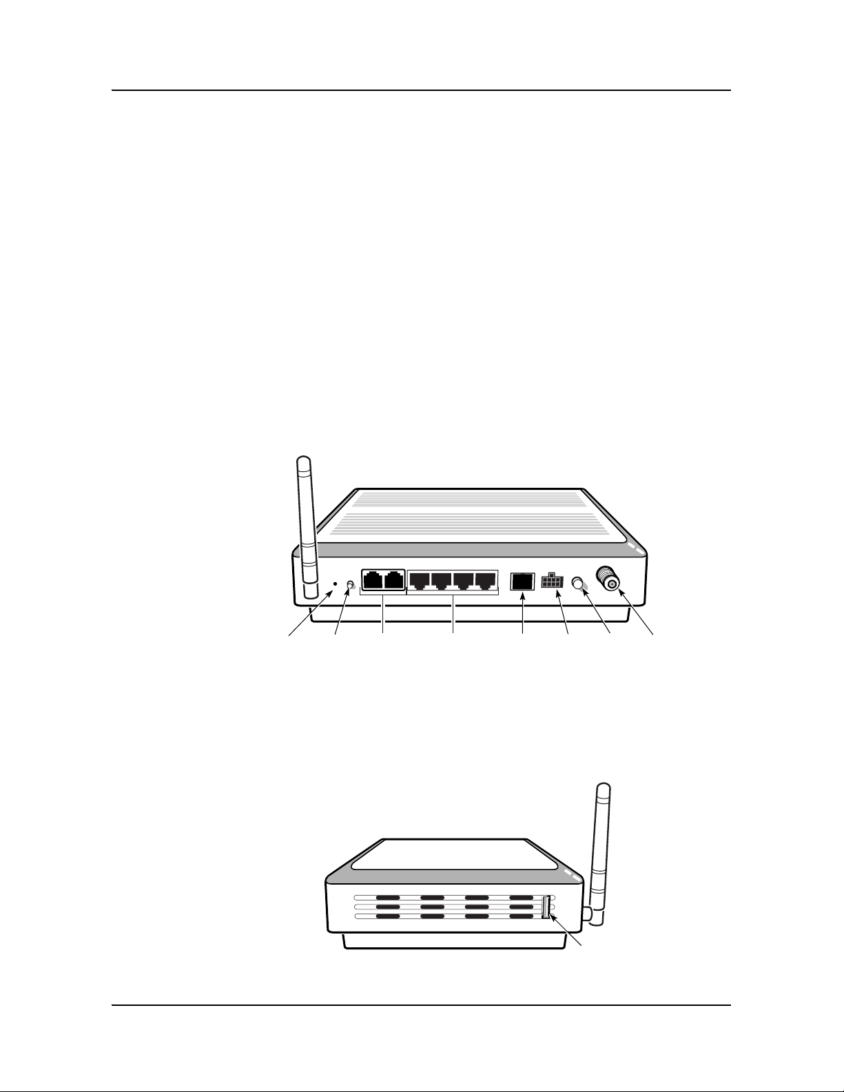
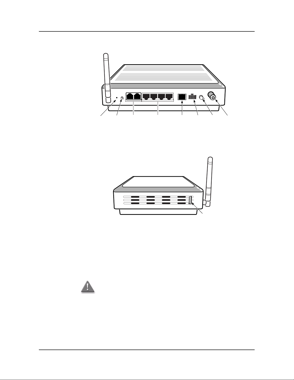
Figure 1-1 shows the physical connections for G-241W-A indoor ONTs.
Figure 1-1 G-241W-A indoor ONT physical connections
Figure 1-2 shows the location of the USB ports on the G-241W-A indoor ONTs.
Figure 1-2 G-241W-A indoor ONT physical connections (USB host ports)
Wi-Fi
Protected
Service button
Reset
button
POTS
ports
(RJ-11)
Ethernet
ports
(RJ-45)
Fiber
optic
connector
Powe r
connector
Powe r
on/off
switch
F-type
coaxial
connector
22788
USB port
22788

1 — G-241W-A unit data sheet
1-6 Alcatel-Lucent 7368 ISAM ONT
Edition 01
I-240W-S I-241W-S I-241W-U Product Guide
Table 1-4 describes the physical connections for G-241W-A indoor ONTs.
Table 1-4 G-241W-A indoor ONT physical connections
Note
(1)
The primary path for the earth ground for these ONTs is provided by the 12V Return signal in the
power connector.
1.5 G-241W-A LEDs
Figure 1-3 shows the G-241W-A indoor ONT LEDs.
Connection
(1)
Description
Ethernet ports This connection is provided through Ethernet RJ-45 cables. Up to four
10/100/1000 Base-T Ethernet interfaces are supported.The Ethernet
ports can support both data and in-band video services on all four
interfaces.
POTS This connection is provided through RJ-11 ports. Up to two POTS
connections are supported.The POTS ports support voice services.
WPS button The Wi-Fi Protected Setup switch is labeled WPS. This button enables
and disables the WPS mode.
RF video coaxial This connection is provided through a F-Type coaxial connector.
Power This connection is provided through the power connector. A power
cable fitted with a Molex connector is used to make the connection.
Fiber optic This connection is provided through a GPON SC/APC fiber optic
connector.
USB ports This connection is provided by two USB host ports, compliant to USB
2.0.
Cables with A-type connectors are used to connect to the USB ports.
1 — G-241W-A unit data sheet
Alcatel-Lucent 7368 ISAM ONT 1-7
Edition 01
I-240W-S I-241W-S I-241W-U Product Guide
Figure 1-3 G-241W-A indoor ONT LEDs
Table 1-5 provides LED descriptions for G-241W-A indoor ONTs.
Table 1-5 G-241W-A indoor ONT LEDs
POWER
LINK
AUTH
LAN1
LAN2
LAN3
LAN4
TEL1
TEL2
VoIP
WPS
WLAN
USB
INTERNET
POWER
LINK
AUTH
LAN1
LAN2
LAN3
LAN4
TEL1
TEL2
VoIP
WPS
WLAN
USB
INTERNET
24510
Indicator LED color and
behavior
LED behavior description
Power Green solid
Red solid
Off
Power on
Light failed on startup (for example corrupt flash), or self test failed on startup,
or self test failed during regular operation or when executed over OMCI
The LED is red by default until the software is running properly and turns it green
Power off
Link Green solid
Off
GPON link between ONT and OLT is operating normally
GPON link is down or no link connected
Auth Green solid
Green flashing
Off
ONT is authorized
In process of ranging or synchronizing on OMCI
ONT is not authorized
(1 of 2)

1 — G-241W-A unit data sheet
1-8 Alcatel-Lucent 7368 ISAM ONT
Edition 01
I-240W-S I-241W-S I-241W-U Product Guide
1.6 G-241W-A detailed specifications
Table 1-6 lists the physical specifications for G-241W-A indoor ONTs.
Table 1-6 G-241W-A indoor ONT physical specifications
Table 1-7 lists the power consumption specifications for G-241W-A indoor ONTs.
LAN 1 to 4 Green solid
Green flashing
Off
Ethernet is linked
LAN activity is present (in either direction)
ONT power off or Ethernet not connected
TEL 1 to 2 Green solid
Green flashing
Off
Off hook
Call in or talking
On hook
VOIP Green solid
Off
VOIP service is OK
VOIP service is not OK
WPS Green solid
Green flashing
Off
Wireless LAN link is up
Wireless LAN link activity
Wireless LAN link down or no link connected
WLAN Green solid
Green flashing
Off
Wireless enabled
Traffic on wireless interface
Wireless is down or no link connected
USB Green solid
Green flashing
Off
At least one USB device is connected
Traffic activity on at least on USB device
No USB device connected
INTERNET Green solid
Green flashing
Off
HSI WAN is connected: a) the device has an IP address assigned from IPCP, DHCP,
or static, and no traffic has been detected; b) the session is dropped due to idle
timeout but the PON link is still present.
PPPoE or DHCP connection in progress
HSI WAN is not connected: a) there is no physical interface connection; b) the
device is in bridged mode without an assigned IP address; c) the session has been
dropped for reasons other than idle timeout.
VIDEO Green
Red
-6 to 0 dBm
Less than -6 dBm
Indicator LED color and
behavior
LED behavior description
(2 of 2)
Description Specification With fiber tray
Length 8.9 in. (22.5 cm) 8.9 in. (22.5 cm)
Width 6.5 in. (16.6 cm) 6.5 in. (16.6 cm)
Height 1.65 in. (4.2 cm) 2.0 in. (5.2 cm)
Weight including [within ± 0.5 lb
(0.23 kg)]
1.12 lb (510 g) 1.3 lb (590 g)

1 — G-241W-A unit data sheet
Alcatel-Lucent 7368 ISAM ONT 1-9
Edition 01
I-240W-S I-241W-S I-241W-U Product Guide
Table 1-7 G-241W-A indoor ONT power consumption specifications
Table 1-8 lists the environmental specifications for G-241W-A indoor ONTs.
Table 1-8 G-241W-A indoor ONT environmental specifications
1.7 G-241W-A GEM ports and T-CONTs
Table 1-9 lists the maximum number of supported T-CONTs and GEM ports.
Table 1-9 G-241W-A indoor ONT capacity for GEM ports and T-CONTs
1.8 G-241W-A performance monitoring statistics
The following section identifies the supported performance monitoring statistics for
G-241W-A ONTs. A check mark indicates the statistic is supported on that ONT. An
empty cell indicates the statistic is not supported. A cell without a check mark
indicates that the counter is not applicable to that type of ONT. The following tables
are categorized by supported alarm types:
• Table 1-10 provides statistics for ONTENET type counters
• Table 1-11 provides statistics for ONTL2UNI type counters
Mnemonic Maximum power
(Not to exceed)
Condition Minimum power Condition
G-241W-A 18 W 2 POTS off-hook, 4 Gig-E, 1 RF
video, Wi-Fi operational
6 W 2 POTS on-hook, other
interfaces/services not
provisioned
Mounting method Temperature range and humidity Altitude
Desk or wall
mounted
Operating:
32°F to 113°F (0°C to 45°C) ambient
temperature
10% to 90% relative humidity, non-condensing
Contact your Alcatel-Lucent technical support
representative for more information
Storage:
68°F to 149°F (20°C to 65°C)
ONT or MDU Maximum Notes
GEM ports per indoor or
outdoor ONT
128 128 are present: 127 are available, 1 is
reserved for OMCI
T-CONTs per indoor or outdoor
ONT
8—
1 — G-241W-A unit data sheet
1-10 Alcatel-Lucent 7368 ISAM ONT
Edition 01
I-240W-S I-241W-S I-241W-U Product Guide
• Table 1-12 provides statistics for PONONTTC, PONONTMCTC,
PONONTTCHSI, PONONTTCCES, PONONTTCFLOW, and
PONONTTCVOIP type counters
• Table 1-13 provides statistics for PONONTTC aggregate type counters
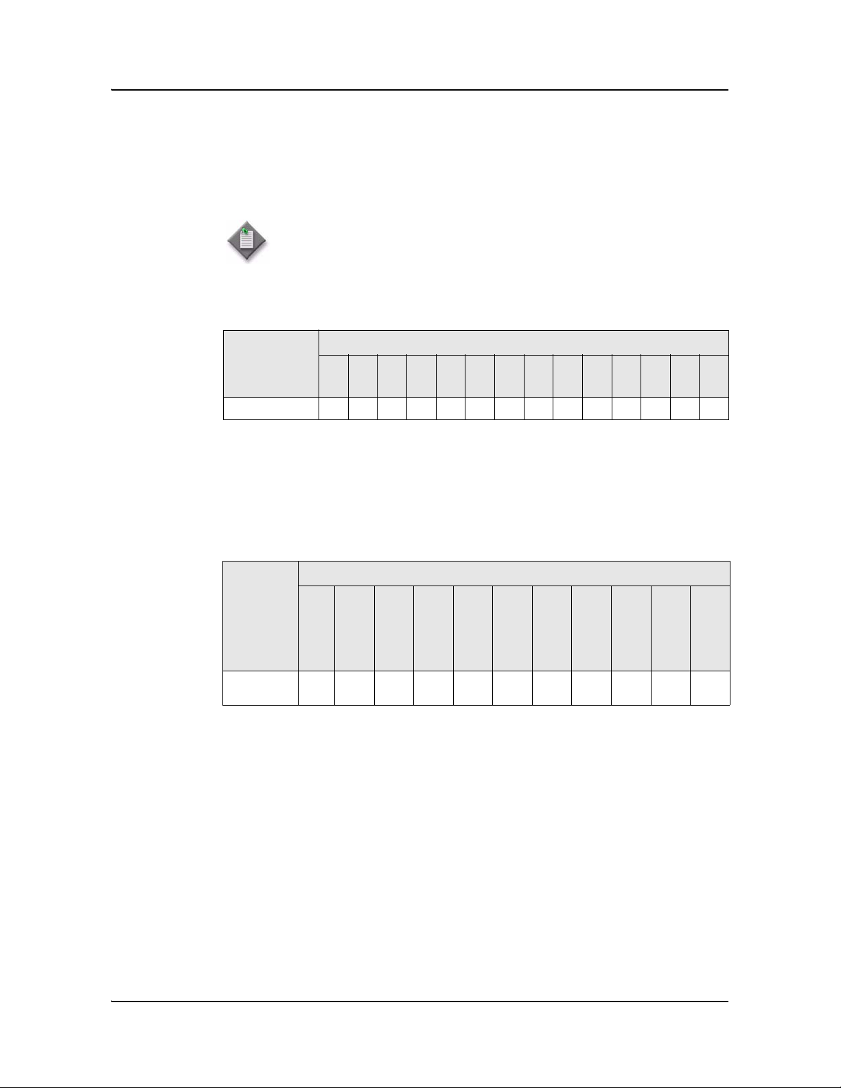
Table 1-10 G-241W-A ONT ONTENET performance monitoring statistics
Note
(1)
A 5 second polling window limitation exists on the ONT, therefore the margin of error for each
15-min window is 5 seconds
Table 1-11 G-241W-A ONT ONTL2UNI performance monitoring statistics
Note
(1)
A 5 second polling window limitation exists on the ONT, therefore the margin of error for each
15-min window is 5 seconds
Note — If you have trouble accessing G-241W-A ONTs performance
monitoring statistics using TL1, please contact your Alcatel-Lucent
support representative for more information about how to access and
retrieve performance monitoring type counters.
ONT ONTENET statistics
FCSE
EC
LC
RBO
SCF
MCF
DT
IMTE
CSE
AE
IMRE
FTL
TBO
SQE
G-241W-A
(1)
✓✓✓✓✓✓✓✓✓✓✓✓✓✓
ONT ONTL2UNI statistics
FRAMES
BYTES
MCFRAMES
DSDRPDFRMS
USDRPDFRMS
USFRAMES
DSFRAMES
USBYTES
DSBYTES
USMCFRAMES
DSMCFRAMES
G-241W-A
(1)
✓✓✓✓✓✓
1 — G-241W-A unit data sheet
Alcatel-Lucent 7368 ISAM ONT 1-11
Edition 01
I-240W-S I-241W-S I-241W-U Product Guide
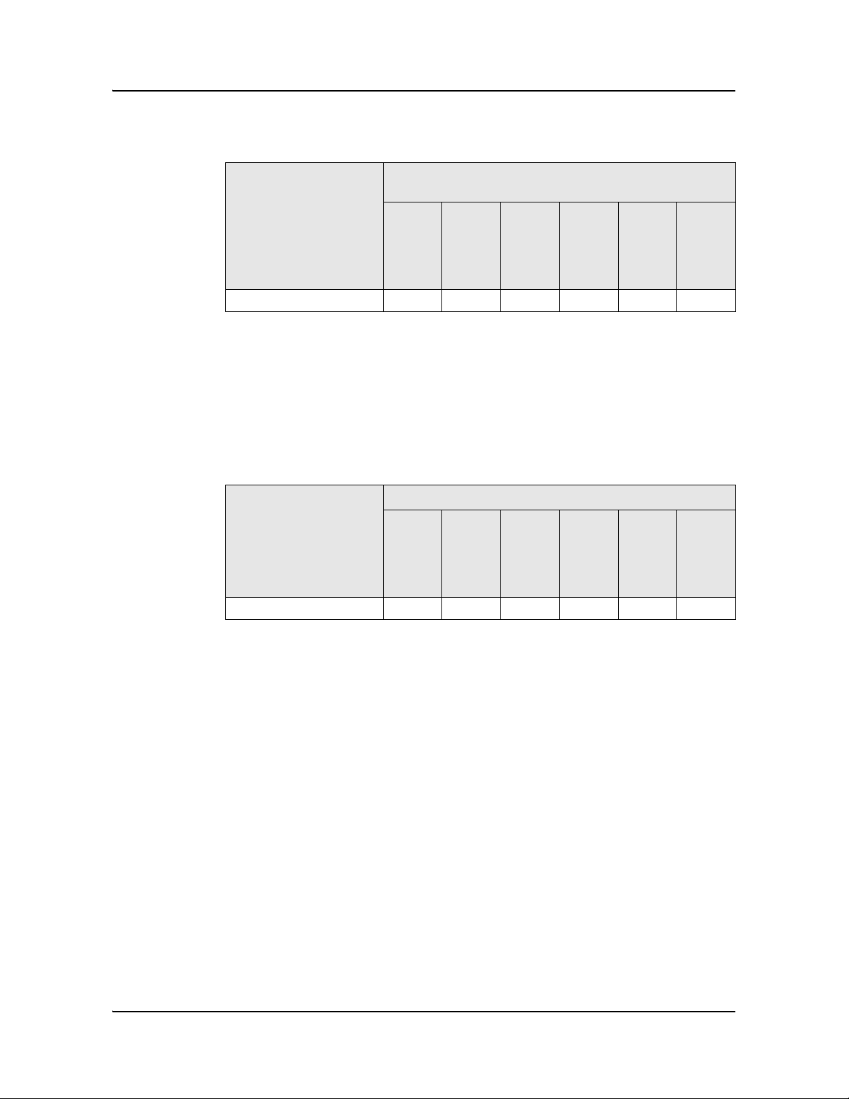
Table 1-12 G-241W-A ONT PONONTTC, PONONTMCTC, PONONTTCHSI, PONONTTCCES,
PONONTTCFLOW, PONONTTCVOIP performance monitoring statistics
Notes
(1)
A 5 second polling window limitation exists on the ONT, therefore the margin of error for each
15-min window is 5 seconds
(2)
TC layer OAM performance monitoring is not supported on the OLT R04.00.10 therefore LOSTFRAGS
and TXFRAG counters are not supported on indoor ONTs.
(3)
The LOSTFRAGS statistic is supported in the downstream direction only.
Table 1-13 G-241W-A ONT PONONTTC aggregate performance monitoring statistics
Notes
(1)
The lost GEM fragment counter supports downstream direction only. Upstream direction is not
supported.
(2)
A 5 second polling window limitation exists on the ONT, therefore the margin of error for each
15-min window is 5 seconds
1.9 G-241W-A functional blocks
Table 1-14 describes the supported interfaces for G-241W-A indoor ONTs.
ONT PONONTTC, PONONTMCTC, PONONTTCHSI, PONONTTCCES,
PONONTTCFLOW, PONONTTCVOIP statistics
TXBLOCKS
TXFRAGS
RXBLOCKS
RXFRAGS
LOSTFRAGS
BADGEMHDRS
G-241W-A
(1)
(2)
(3)
✓✓✓✓✓✓
ONT PONONTTC (aggregate) statistics
TXBLOCKS
TXFRAGS
RXBLOCKS
RXFRAGS
LOSTFRAGS
(1)
BADGEMHDRS
G-241W-A
(2)
✓✓✓✓✓✓
1 — G-241W-A unit data sheet
1-12 Alcatel-Lucent 7368 ISAM ONT
Edition 01
I-240W-S I-241W-S I-241W-U Product Guide
Table 1-14 G-241W-A indoor ONT interfaces
G-241W-A indoor ONTs are single-residence ONTs that support Wireless (Wi-Fi)
service. Wi-Fi service on these ONTs are compliant with the IEEE 802.11 standard
and enabled or disabled using a radio on/off switch.
In addition to the Wi-Fi service, these ONTs transmit Ethernet packets to four RJ-45
Ethernet ports, and voice traffic to two RJ-11 POTS ports. These ONTs have two
USB ports also.
The ONTs also support RF video traffic on one F-type coaxial connector. The ONTs
feature fiber optic and power connectors.
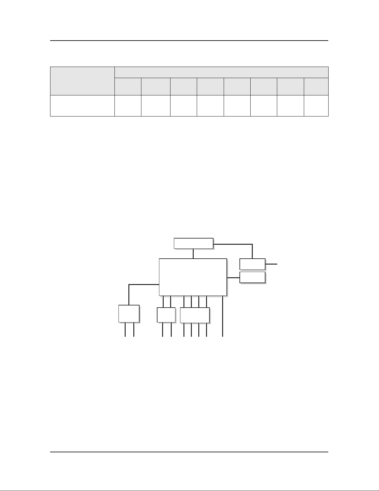
Figure 1-4 shows functional blocks for G-241W-A indoor ONTs.
Figure 1-4 Single-residence Wi-Fi ONT with Gigabit Ethernet and POTS and with RF video
ONT SoC technology serves as the main hardware block for these ONTs; see
Figure 1-5.
ONT category
description
Interface capacity
POTS
ports
Ethernet
ports
VDSL2 MoCA RF
Video
HPNA Wi-Fi USB
Single-residence Wi-Fi
ONTs with Gig-E ONTs,
POTS, with RF video
24——1—11
Internal
USB host
PWR
F-type connector
4xRJ452xRJ11
22570
Triplexer
GE PHY
switch
RF or
HPNA filter
RESET
GPON
SOC
POTS
2xUSB
External
USB
Host
1 — G-241W-A unit data sheet
Alcatel-Lucent 7368 ISAM ONT 1-13
Edition 01
I-240W-S I-241W-S I-241W-U Product Guide
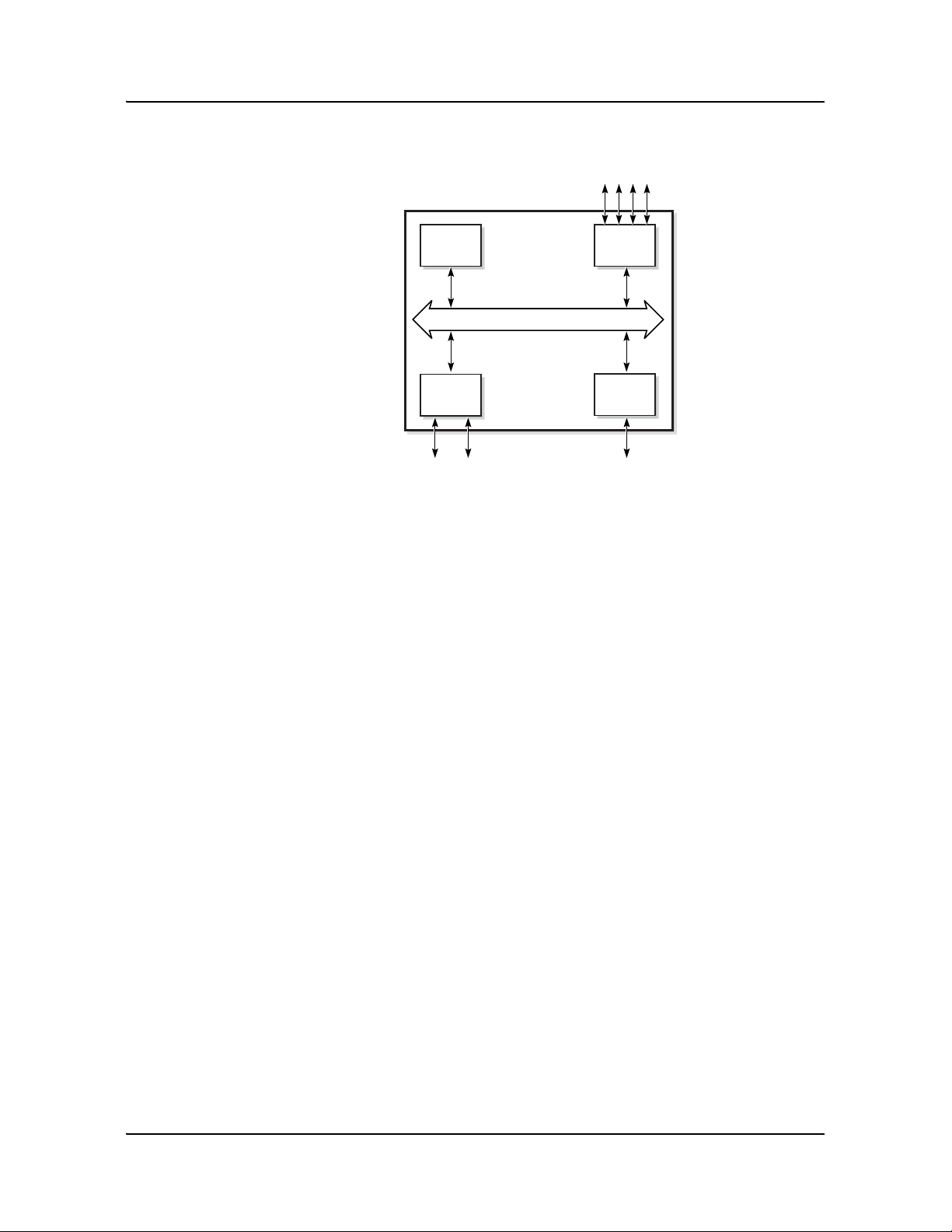
Figure 1-5 G-241W-A ONT hardware block
ONT SoC technology consists of five key elements:
• GPON MAC
The Gigabit Passive Optical Network Media Access Control (GPON MAC)
element on the SoC terminates the GPON interface using an optical diplexer. This
interface supports GPON as described in G.984.3 (GPON TC Layer) ITU
specification.
• Ethernet MAC
The SoC provides up to four GE MACs.
• DSP interface
The Digital Signal Processor (DSP) provides voice processing for 2 POTS lines
with the 3-way calling. The DSP has a dedicated 64 kbyte instruction cache and
shares a 32 kbyte data cache with the Control Processor.
• Control Processor
The Control Processor features an integral memory management unit that
supports a dedicated 64 kbyte instruction cache and shares a single 32 kbyte data
cache with the DSP. The Control Processor and DSP also include a single channel
Data Management Application (DMA) controller with a 4 kbyte read ahead
low-latency Dynamic Random Access Memory (DRAM) access port. The
processors typically run at 400 MHz.
• Switch matrix
The Switch matrix provides an integrated data channel between the four GE
MACs, the GPON MAC, the DSP, the control processor, and the other integrated
elements such as flash memory, DRAM, and the local bus controller.
These ONTs can also interact with additional hardware components to support
functionality not provided by the SoC technology.
Control
processor
Ethernet
MACs
Ethernet ports GPON
POTS ports
DSP
GPON
MAC
SoC
19421
SoC Bridge

1 — G-241W-A unit data sheet
1-14 Alcatel-Lucent 7368 ISAM ONT
Edition 01
I-240W-S I-241W-S I-241W-U Product Guide
1.10 G-241W-A standards compliance
G-241W-A indoor ONTs are compliant with the following standards:
• 802.11b support for maximum transmit power (EIRP) equal to or greater than 200
mW (23.01 dBm)
• 802.11g support for maximum transmit power (EIRP) equal to or greater than 100
mW (20 dBm)
• 802.11n support for wireless LAN interface
• G.711a/u, G-729 CODEC
• G.984 support GPON interface (framing)
• G.984.2 support for Amd1, class B+
• G984.5 support for optical and other transport network infrastructures
• Wi-FI: WEP/WPA/WPA2, WPA-PSK/WPA2-PSK
1.11 G-241W-A special considerations
G-241W-A are package D ONTs.
G-241W-A indoor ONT considerations and limitations
Table 1-15 lists the considerations and limitations for Package D G-241W-A ONTs.
Table 1-15 G-241W-A ONT considerations and limitations
Upgrade considerations and limitations
Existing ONTs that use 7342 ISAM FTTU releases older than R04.06.xx and
R04.07.xx must be upgraded to use R04.00.10 software while assigned to a PON ID
value smaller than 64. For this purpose, if split ratios larger than 1:64 are being
deployed, you may choose to set aside the first PON ID as a staging point.
Considerations and limitations
The ONT pads packets to 104 as SoC limitation
Due to a Layer 3 packet processing limitation, the ONT can handle up to 220Mb/s (@ up to 72 bytes
for Ethernet Frame sizes. Rates that exceed 220Mb/s with Ethernet frame sizes of less than 72 bytes
will result in dropped frames at the ONT.
The uplink port of the SoC chipset is limited to 1 Gb/s
Some parameters are system level, not line level; for example, enable_caller_id, digitmap.
Most parameters can be configured in either OMCIv2 or XML.The OMCIv2 configuration values
generally take precedence over the XML ones.
Specifically, when voice parameters are configured using OMCIv2, attempting to overwrite the
configuration using XML will have no effect.
The release timer, rls-timer, needs to be configured in OMCIv2, because when it is not, the default
OLT value will be applied, not the XML value.

1 — G-241W-A unit data sheet
Alcatel-Lucent 7368 ISAM ONT 1-15
Edition 01
I-240W-S I-241W-S I-241W-U Product Guide
G-241W-A indoor ONTs support voice, video, and data services. These ONTs,
which feature Wi-Fi technology, can also function as a residential gateway with layer
2 and layer 3 processing capabilities.
G-241W-A ONT supported modes
The G-241W-A ONT supports one of two modes at any given time. The supported
modes are
• ONT
• Residential gateway
For more information, see G-241W-A ONT supported features in the Configure a
G-241W-A indoor ONT chapter.

1 — G-241W-A unit data sheet
1-16 Alcatel-Lucent 7368 ISAM ONT
Edition 01
I-240W-S I-241W-S I-241W-U Product Guide

Alcatel-Lucent 7368 ISAM ONT 2-1
Edition 01
I-240W-S I-241W-S I-241W-U Product Guide
2 — Install a G-241W-A indoor ONT
2.1 Purpose 2-2
2.2 General 2-2
2.3 Prerequisites 2-2
2.4 Recommended tools 2-2
2.5 Safety information 2-3
2.6 Procedure 2-4

2 — Install a G-241W-A indoor ONT
2-2 Alcatel-Lucent 7368 ISAM ONT
Edition 01
I-240W-S I-241W-S I-241W-U Product Guide
2.1 Purpose
This chapter provides the steps to install a G-241W-A indoor ONT.
2.2 General
The steps listed in this chapter describe mounting and cabling for G-241W-A indoor
ONTs.
2.3 Prerequisites
You need the following items before beginning the installation:
• all required cables
2.4 Recommended tools
You need the following tools for the installation:
• #2 Phillips screwdriver
• 1/4 in. (6 mm) flat blade screwdriver
• wire strippers
• fiber optic splicing tools
• RJ-45 cable plug crimp tool
• voltmeter or multimeter
• optical power meter
• drill and drill bits
• cable ties
• paper clip

2 — Install a G-241W-A indoor ONT
Alcatel-Lucent 7368 ISAM ONT 2-3
Edition 01
I-240W-S I-241W-S I-241W-U Product Guide
2.5 Safety information
Read the following safety information before installing the unit.
Danger 1 — Hazardous electrical voltages and currents can cause
serious physical harm or death. Always use insulated tools and follow
proper safety precautions when connecting or disconnecting power
circuits.
Danger 2 — Make sure all sources of power are turned off and have
no live voltages present on feed lines or terminals. Use a voltmeter to
measure for voltage before proceeding.
Danger 3 — Always contact the local utility company before
connecting the enclosure to the utilities.
Warning — This equipment is ESD sensitive. Proper ESD
protections should be used when removing the fiber access cover of
the indoor ONT.
Caution — Keep indoor ONTs out of direct sunlight. Prolonged
exposure to direct sunlight can damage the unit.
Note 1 — Observe the local and national laws and regulations that
may be applicable to this installation.
Note 2 — Observe the following:
• The indoor ONT should be installed in accordance with the
applicable requirements of the NEC or CEC. Local authorities and
practices take precedent when there is conflict between the local
standard and the NEC or CEC.
• The indoor ONT must be installed by qualified service personnel.
• Indoor ONTs must be installed with cables that are suitably rated
and listed for indoor use.
• See the detailed specifications in the G-241W-A unit data sheet for
the temperature ranges for these ONTs.
2 — Install a G-241W-A indoor ONT
2-4 Alcatel-Lucent 7368 ISAM ONT
Edition 01
I-240W-S I-241W-S I-241W-U Product Guide
2.6 Procedure
Use this procedure to install a G-241W-A indoor ONT.
1 Place the indoor ONT unit:
a On the flat surface, such as a desk.
i Wrap the excess optic cable inside the fiber storage tray.
ii Attach the fiber storage tray to the ONT.
iii Place the ONT on the flat surface, horizontally resting on its four feet.
b On a wall.
i Determine whether to mount the G-241W-A indoor ONT in either the
vertical or horizontal position. If possible, mount the ONT on a wall
stud.
ii Mark the wall with the location of the mounting holes shown in
Figures 2-1 and 2-2. These holes should be the same distance apart as
the distance between the centers of the keyholes on the ONT. Use the
one of the two available fiber storage trays as a wall mounting template
to indicate the location of the mounting holes on the wall.
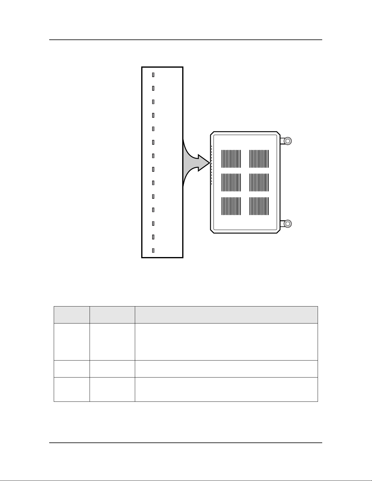
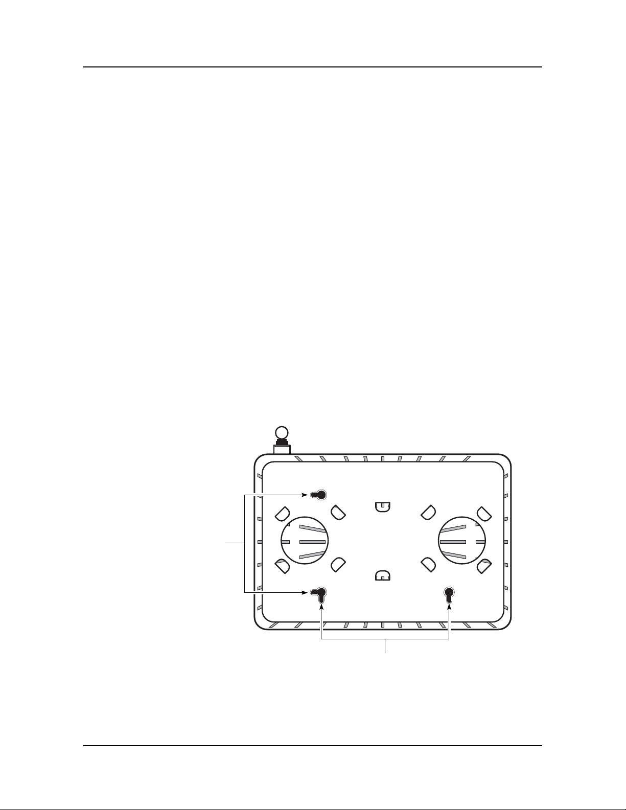
Figure 2-1 Wall mounting keyholes of the G-241W-A indoor ONT with fiber stor age tray
attached
22441
Vertical
mounting
keyholes
Horizontal mounting keyholes
2 — Install a G-241W-A indoor ONT
Alcatel-Lucent 7368 ISAM ONT 2-5
Edition 01
I-240W-S I-241W-S I-241W-U Product Guide
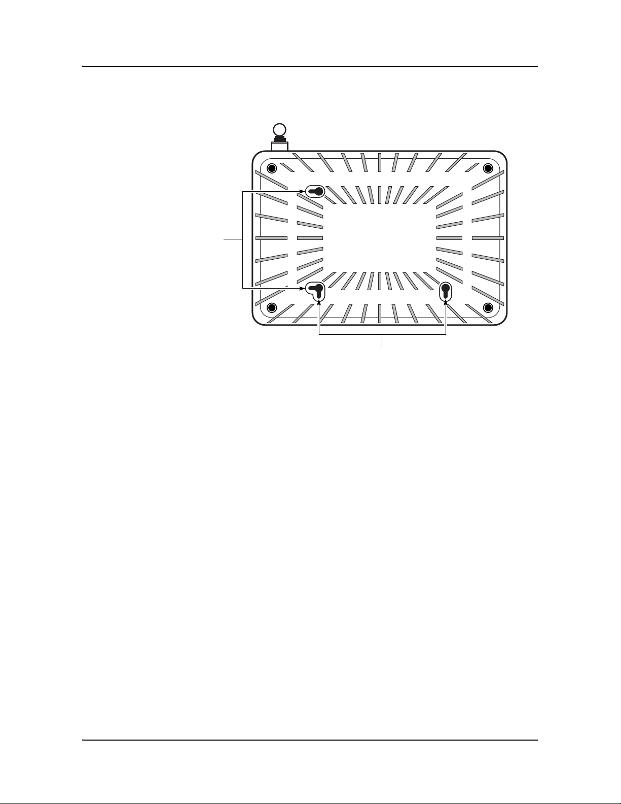
Figure 2-2 Wall mounting keyholes of the G-241W-A indoor ONT without fiber storage
tray attached
iii Attach the fiber storage tray to the wall by drilling the holes in the wall
where the tray will be mounted and then drive the mounting screws into
the holes.
Do not drive the mounting screws into the wall completely. Leave
approximately 1/8 in. (6 mm) between the screw head and the wall
surface.
iv Wrap the optic cable around the spools in the fiber storage tray.
v Attach the fiber storage tray to the wall by placing the screw heads of
the mounting screws into the wall mounting holes, either vertical or
horizontal, on the tray.
vi Slide the ONT enclosure over the fiber storage tray at a forty-five
degree angle and seat the ONT securely on the tray.
Aligning features molded into the fiber storage tray and ONT enclosure
interlock allowing the ONT to seat on the tray.
2 Review the connection locations as shown in Figures 2-3 and 2-4.
22443
Vertical
mounting
keyholes
Horizontal mounting keyholes
2 — Install a G-241W-A indoor ONT
2-6 Alcatel-Lucent 7368 ISAM ONT
Edition 01
I-240W-S I-241W-S I-241W-U Product Guide
Figure 2-3 G-241W-A indoor ONT connections
Figure 2-4 G-241W-A indoor ONT connections (USB host port)
3 Connect the Ethernet cables directly to the RJ-45 ports. See Figure 2-3 for the
location of the RJ-45 ports.
4 Connect the POTS cables directly to the RJ-11 ports. See Figure 2-3 for the
location of the RJ-11 ports.
5 If used, connect the coaxial cable to the F-type connector. See Figure 2-3 for the
location of the F-type connector.
Danger — A shock hazard exists when working with the coaxial cable
for the RF video connection. Wear protective gloves and take all
necessary precautions to ensure personal safety.
Wi-Fi
Protected
Service button
Reset
button
POTS
ports
(RJ-11)
Ethernet
ports
(RJ-45)
Fiber
optic
connector
Powe r
connector
Powe r
on/off
switch
F-type
coaxial
connector
22788
USB port
22788

2 — Install a G-241W-A indoor ONT
Alcatel-Lucent 7368 ISAM ONT 2-7
Edition 01
I-240W-S I-241W-S I-241W-U Product Guide
6 Connect the SC/APC fiber optic cable directly to the ONT. See Figure 2-3 for
location of the fiber optic c onnector.
7 Install the power supply according to manufacturer specifications.
8 Con nect the power cable with an 8-pin Molex connector to the power supply.
9 Con nect the power cable with an 8-pin Molex connector to the ONT unit; see
Figure 2-5 for the Molex pin alignment.
Note 1 — Observe the following:
• To comply with FCC standards, use either RG-6 or RG-59 coaxial
cable. Also, proper attenuation must be inserted at the coaxial
output to guarantee that at the end of any coaxial drop, every video
signal is below 15.5 dBmV and audio signals are below 2.55 dBmV
(per channel).
• You may need to install the 75-ohm coaxial F connector on the video
cable.
Note 2 — Observe the following when connecting the F-type coaxial
connector to the coaxial connector on the ONT:
• Fully tighten the F-type connector on the cable by hand before using
a wrench to complete tightening (up to a maximum of an additional
1/8 turn). If using a torque wrench (as is recommended) to tighten
the connector, the torque setting should be between a minimum of
20 in-lbs and a maximum of 40 in-lbs. The connector should be tight
enough when the task is complete that it can not be unscrewed by
hand.
Danger — Fiber cables transmit invisible laser light. To avoid eye
damage or blindness, never look directly into fibers, connectors, or
adapters.
Warning — Be careful to maintain a bend radius of no less than 1.5 in.
(3.8 cm) when connecting the fiber optic cable. Too small of a bend
radius in the cable can result in damage to the optic fiber.
Note — Fiber cable preparation varies depending on the type and size
of the inside or outside plant fiber cable being spliced to the SC/APC
fiber optic pigtail cable.
Warning — To avoid the possibility of damage to the pins on the power
cable connector, carefully align the pins on the connector on the cable
with the pin holes in the power connector on the ONT before making the
connection.

2 — Install a G-241W-A indoor ONT
2-8 Alcatel-Lucent 7368 ISAM ONT
Edition 01
I-240W-S I-241W-S I-241W-U Product Guide
Figure 2-5 Molex 8-pin connector
10 Power up the ONT unit by using the on/off power switch; see Figure 2-3 for the
location of the power switch.
11 If used, enable the Wi-Fi service, as described in Configure a G-241W-A indoor
ONT.
12 Verify the ONT LEDs, voltage status, and optical signal levels; see the 7368
Hardware and Cabling Installation Guide.
13 Activate and test the services; see the 7368 Hardware and Cabling Installation
Guide.
14 If used, configure the SLID; see the 7368 ISAM ONT Configuration, Management,
and Troubleshooting Guide for more information.
15 If necessary, reset the ONT.
i Access the Rest button. See Figure 2-3 for the location of the Reset button.
ii Insert the end of a straightened paper clip or other narrow object into the
hole in the Reset button to reset the ONT.
16 STOP. This procedure is complete.
Note — Observe the following:
• Only Pins 1, 2, and 7 in the Molex connector pin arrangement shown
in Figure 2-5 are used with G-241W-A indoor ONTs.
Pin 2 Pin 8
Pin 1 Pin 3 Pin 7
20179

Alcatel-Lucent 7368 ISAM ONT 3-1
Edition 01
I-240W-S I-241W-S I-241W-U Product Guide
3 — Replace a G-241W-A indoor ONT
3.1 Purpose 3-2
3.2 General 3-2
3.3 Prerequisites 3-2
3.4 Recommended tools 3-2
3.5 Safety information 3-3
3.6 Procedure 3-4
 Loading...