


Service Manual for L1 and L2
Nokia Asha 501
Nokia Asha 501 Dual SIM
RM-899, RM-900 (Single SIM)
RM-902 (Dual SIM)
Key features
zTotally new Asha Platform OS
zFastlane with Swipe Motion
zSocial and always connected
z3.0" QVGA display
zCapacitive touch panel
Version 1.0
Check the repair policy before performing any mechanical repair on Service Level 1&2!
Exploded view |
Disassembly steps |
Assembly hints |
More |
More |
More |
Service devices |
Product controls and interfaces |
Solder components |
More |
More |
More |
Service concept
More
©2013 Nokia | Nokia Internal Use only | All Rights Reserved.

Service Manual Level 1 and 2 |
Exploded view |
||
Nokia Asha 501, Nokia Asha 501 Dual SIM |
|||
RM-899 RM-900 (Single SIM), RM-902 (Dual SIM) |
|
||
Version 1.0 |
|
|
|
1 |
A-COVER AND TOUCH ASSEMBLY |
|
|
(I0001 - I0003) |
|
||
|
|
|
TOUCH PANEL |
|
|
A-COVER |
I0002 |
|
|
I0001 |
|
|
|
EARPIECE |
|
|
|
I0003 |
|
|
|
|
|
|
|
|
BACK KEY |
|
|
|
I0004 |
|
|
DISPLAY |
|
|
|
I0013 |
|
2 |
LIGHT SWAP PACKAGE |
|
|
(I0005 - I0012) |
FEM SHIELDING LID |
||
|
|||
BB SHIELDING LID |
I0009 |
||
|
|
|
|
|
|
I0008 |
LCD CONDUCTIVE ADHESIVE |
|
|
TOUCH IC GASKET |
|
|
|
I0011 |
|
|
|
I0006 |
|
|
|
|
|
|
|
LIGHT SWAP PWB |
TYPE LABEL |
|
|
I0007 |
|
|
|
I0012 |
|
|
|
|
|
|
|
CAMERA |
WLAN SHIELDING LID |
|
|
I0010 |
|
|
|
I0005 |
|
|
|
|
|
|
|
D-COVER ASSEMBLY |
IHF SPEAKER |
|
3(I0014 - I0018) |
I0014 |
|
|
|
||
 D-COVER I0018
DC JACK I0017
B-COVER
I0022
SPEAKER GASKET I0015
SPEAKER MESH I0016
ANTENNA MODULE I0019
RELEASE BUTTON I0020
SCREW TORX+ SIZE 6 RF 1.6 x 5.0 I0021
v1.0 |
|
|
|
|
|
Only available |
Not reuseable |
Repair/swap |
|
|
|
|
|
|
as assembly |
after removal |
only in level 3 |
|
|
|
|
|
|
|
|
|
©2013 Nokia | Nokia Internal Use only | All Rights Reserved.
Service Manual Level 1 and 2
Nokia Asha 501, Nokia Asha 501 Dual SIM
RM-899 RM-900 (Single SIM), RM-902 (Dual SIM) Version 1.0
Disassembly steps
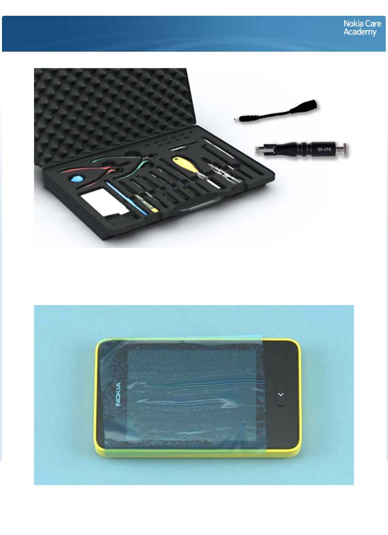
1) For disassembling you need the Nokia Standard toolkit version 2. You will also need a DC plug and the camera removal tool SS-276.
Disassembly instructions are made with dual SIM variant.
2) Protect the A-COVER with protective film.
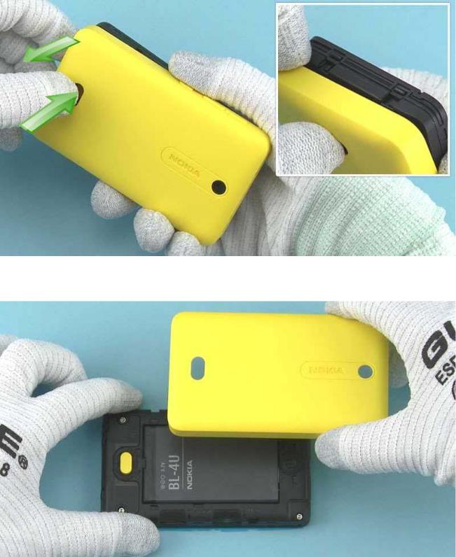
3) To detach the B-COVER press the RELEASE BUTTON and then pull the B-COVER with fingers.
4) Remove the B-COVER.

5) Use the finger notch to pull out and remove the battery.
6) Unscrew the four Torx+ size 6 screws in the order shown. Do not use them again.

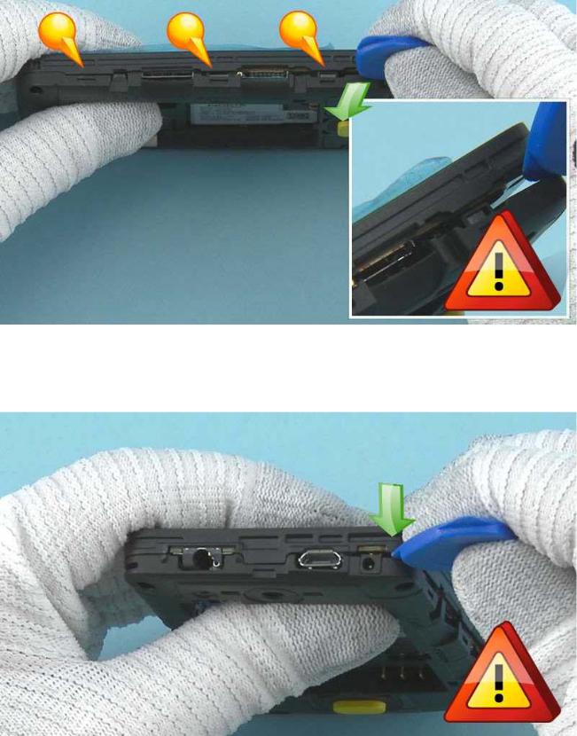
7) Start releasing the A-COVER from the bottom end of the device. Insert the SRT-6 between the A- COVER and D-COVER and release the two clips holding the A-COVER.
NOTE: SRT-6 must be inserted vertically to avoid damages in covers.
8) Continue to release the A-COVER by inserting the SRT-6 into the gap between the A-COVER and D- COVER on the memory card side of the device.
NOTE: SRT-6 must be inserted vertically to avoid damages in covers.
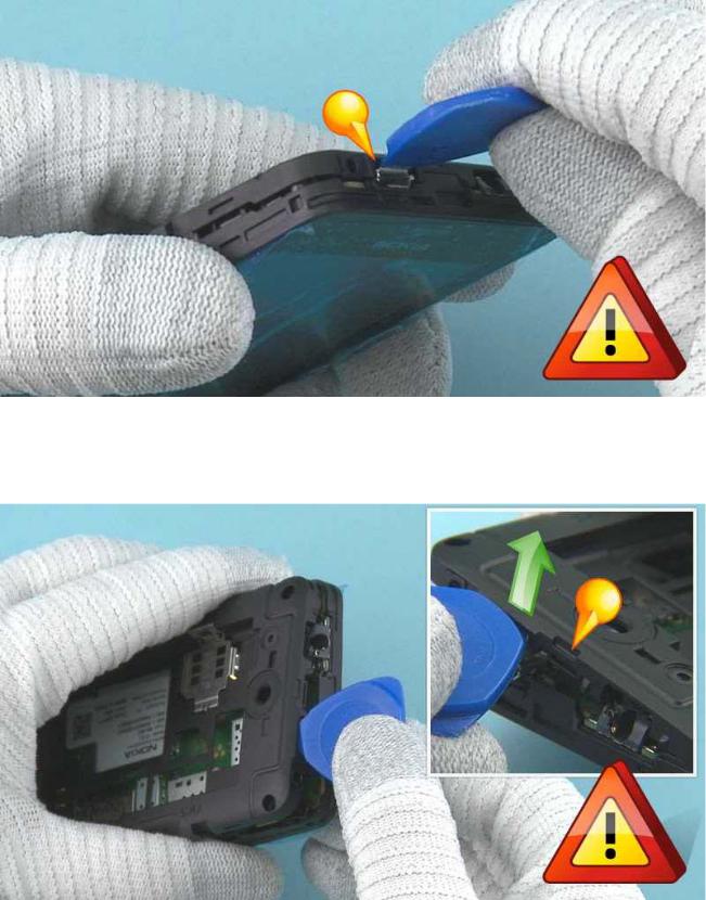
9) Pull the D-cover to direction shown to release the shown clips. Pay attention not to damage the A-COVER.
10) Release the top corner using the SRT-6 in the same way.
NOTE: SRT-6 must be inserted vertically to avoid damages in covers.
11) To release the top end insert the SRT-6 into to the gap between USB and D-COVER. Be careful not to damage the USB connector.
12) Lift the D-COVER upwards to release the clip next to the USB. Pay attention not to damage the covers or the USB connector.
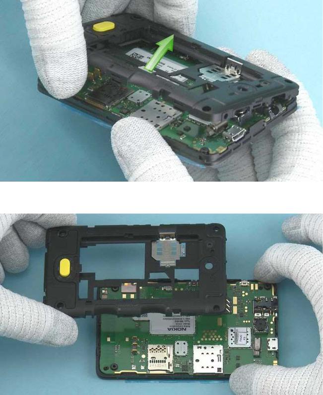
13) Lift the D-COVER as shown.
14) Remove the D-COVER.
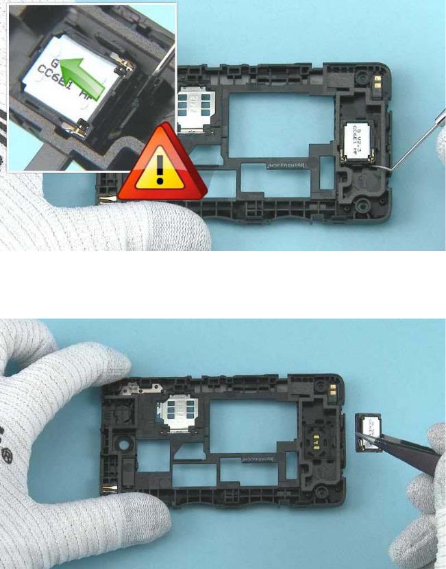
15) Use the dental tool to lever out the IHF SPEAKER.
Be careful not to injure yourself with the sharp end of the dental tool.
16) Use tweezers to remove the IHF SPEAKER.
17) Use the dental tool to detach the SPEAKER GASKET.
18) Use tweezers to remove the SPEAKER GASKET. Do not use it again. Discard it.
 Loading...