


Service Manual for L1 and L2
Nokia Lumia 510
RM-889 RM-898
Key features
zWindows Phone 7.5 / 7.8 OS
zLarge 4" display
z5 Megapixel camera
z800 MHz Snapdragon processor
z256 MB RAM, 4GB internal storage + SkyDrive
Check the repair policy before performing any mechanical repair on Service Level 1&2!
Version 1.0
Exploded view |
Disassembly steps |
Disassembly video |
More |
More |
More |
Assembly hints |
Assembly video |
Solder components |
More |
More |
More |
Service devices |
Product controls and interfaces |
Service concept |
More |
More |
More |
Phone reset
More
©2012 Nokia | Nokia Internal Use only | All Rights Reserved.

Service Manual Level 1 and 2
Nokia Lumia 510
RM-889 RM-898
Version 1.0
Exploded view
TOUCH PANEL ASSEMBLY
(I0001, I0002)
TOUCH PANEL
I0002 TP/LCM SPONGE
I0001
LIGHT GUIDE DISPLAY I0004
I0003
2 A-COVER ASSEMBLY
(I0005, I0006)
A-COVER
I0006
POWER KEY
I0010
EARPIECE
I0007
3 |
LIGHT SWAP PACKAGE |
(I0011-I0023) |
|
|
MYLAR USB |
|
I0023 |
PROXIMITY SENSOR RUBBER |
|
|
I0016 |
|
MYLAR RECEIVER |
|
I0022 |
|
LIGHT SWAP PWB |
|
I0011 |
|
TP CONNECTOR RUBBER |
|
I0018 |
|
TYPE LABEL |
|
I0014 |
4 |
CAMERA |
I0024 |
|
D-COVER ASSEMBLY |
|
(I0026-I0029) |
|
GPS ANTENNA |
|
|
I0028 |
|
D-COVER |
|
I0029 |
SCREW TORX+ SIZE 5
I0030
TOUCH PANEL ADHESIVE I0005
CAMERA KEY
I0009
VOLUME KEY
I0008
MIC RUBBER
I0015
SEARCH KEY LED SPONGE I0020
BACK & HOME KEY LED SPONGE I0019
SPEAKER SEALING SPONGE I0021
LCD CONNECTOR RUBBER I0017
RF SHIELD I0012
BASEBAND SHIELD
I0013
IHF SPEAKER
I0025
SPEAKER MESH
I0026
MAIN ANTENNA
I0027
BATTERY COVER
I0031
v1.0 |
Only available |
Not reuseable |
Repair/swap |
|
as assembly |
after removal |
only in level 3 |
||
|
||||
|
|
|
|
©2012 Nokia | Nokia Internal Use only | All Rights Reserved.
Service Manual Level 1 and 2
Nokia Lumia 510
RM-889 RM-898
Version 1.0
Disassembly steps
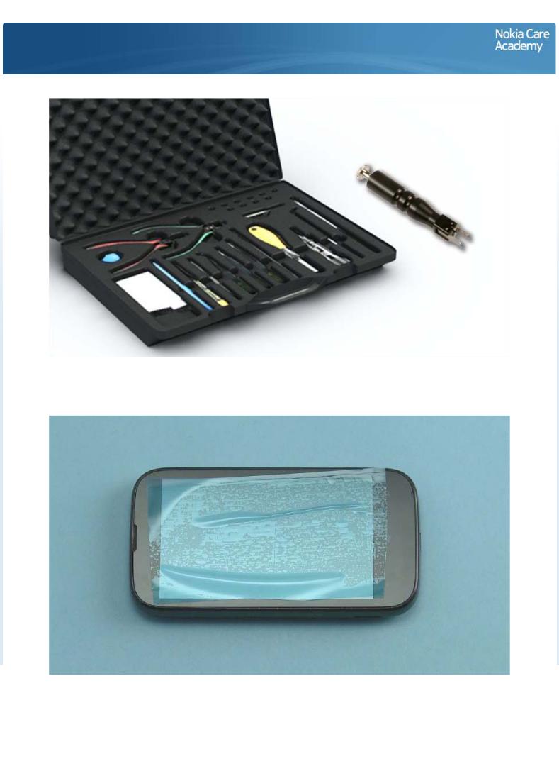
For disassembling you need the Nokia Standard toolkit version 2. You will also need the camera removal tool SS-287.
Protect the TOUCH SCREEN with protective film.
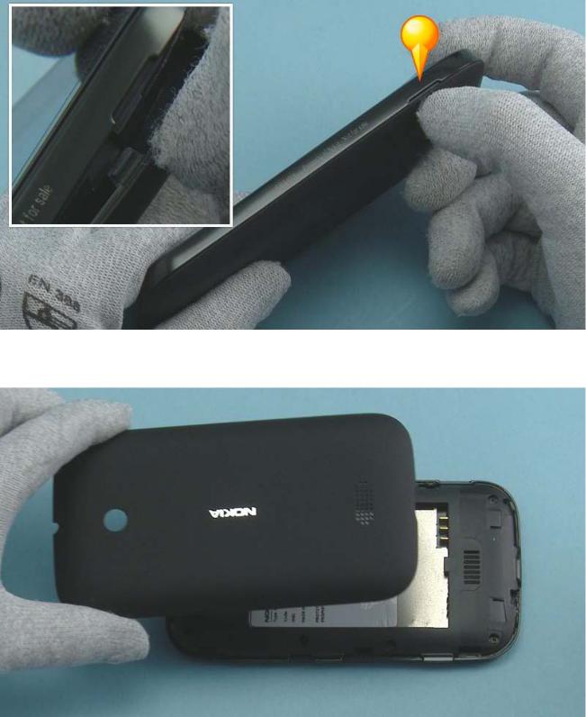
Use the finger groove to release the BATTERY COVER.
Remove the BATTERY COVER. If there is a battery inside, remove it also.
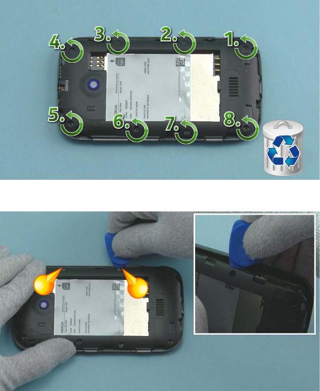
Unscrew the eight TORX+ size 5 screws in the order shown. Do not use the screws again. Discard them.
Use the srt-6 to release these two snaps.

Release also these two snaps on the the other side of the device.
Lift up the D-COVER ASSEMBLY bottom end first.
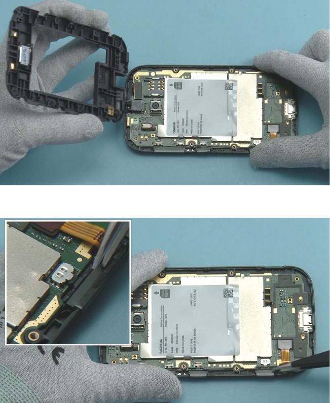
Remove the D-COVER.
Use tweezers to remove the CAMERA KEY.
Remove the POWER KEY.
Remove also the VOLUME KEY.
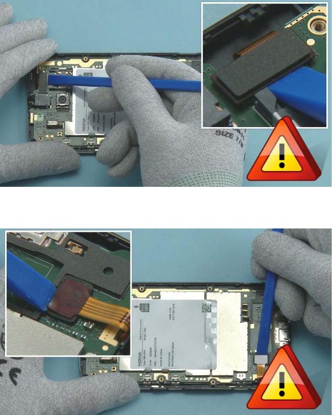
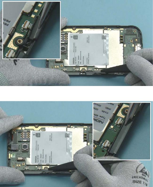
Disconnect the touch connector with the SS-93. Be careful not to damage the rubber around the connector or any components nearby.
Disconnect the DISPLAY connector with the SS-93. Be careful not to damage the rubber around the connector or any components nearby.
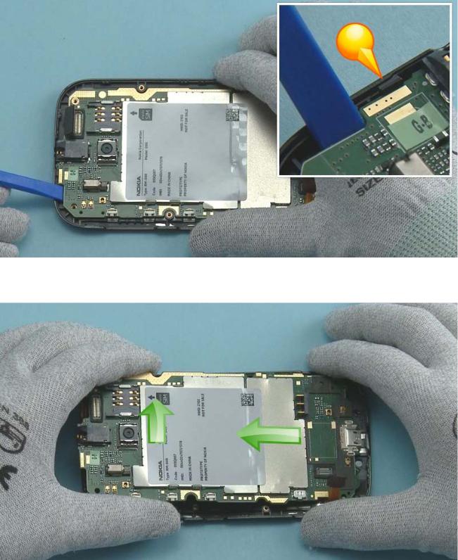
Release the clip holding the ENGINE BOARD with the SS-93.
Lift up The ENGINE BOARD as shown.
Carefully release the EARPIECE with the dental tool. Be careful not to injure yourself with the sharp end of the dental tool.
Remove the EARPIECE. Do not use it agin. Discard it.
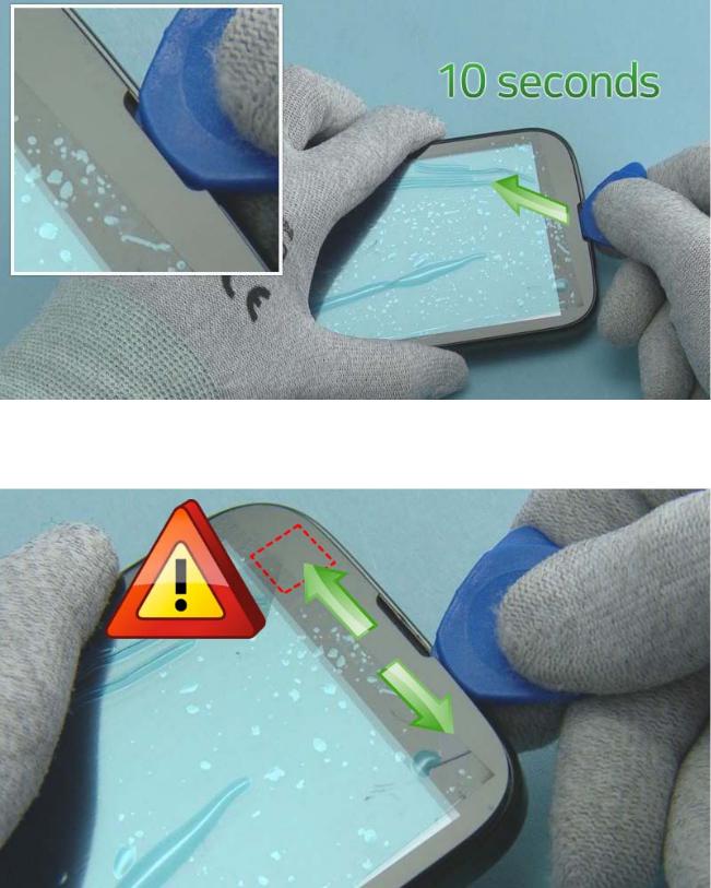
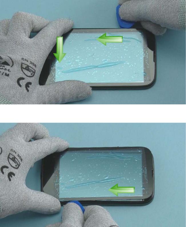
Insert the SRT-6 into the earpiece hole. Carefully lift up the TOUCH PANEL for 10 seconds to loosen the adhesive.
Continue detaching the TOUCH PANEL by sliding the SRT-6 to the right. Then slide the SRT-6 to the left. Be careful not to damage the flex underneath.
Continue by releasing the TOUCH PANEL side and the bottom end with the SRT-6.
Release also the other side with the SRT-6.
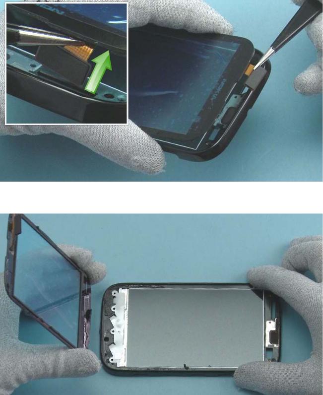
Use tweezers to pull the connector flex through the A-COVER hole.
Separate the A-COVER and the TOUCH PANEL.
 Loading...