


CR 1200
CR 1100, CR 1200, CR 1400
Instructions For Use
Instrucciones de uso
2/09
FORM NO. 56041797
Printed in USA
A-English
B-Español
Obsolete Nilfi sk MODELS 56304009, 56304010, 56304011, 56304012, 56304013, 56304014,
56304015, 56304016, 56304017
Active Nilfi sk MODELS 56306059, 56306060, 56306061, 56306062, 56306063, 56306064,
56307236(HT), 56307238(HT)
All model numbers starting with “56306” and “56307” are manufactured with the 2007
certifi ed engine.

FORM NO. 56041797 - CR 1100, 1200, 1400 - A-3
ENGLISH / A-3
TABLE OF CONTENTS
Page
Introduction ...................................................................................A-4
Parts and Service ...........................................................................A-4
Nameplate ......................................................................................A-4
Uncrating the Machine .................................................................... A-4
Cautions and Warnings ..................................................................A-5
Consignes de prudence et de sécurité ...........................................A-6
General Information ........................................................................A-7
Know Your Machine / Operator’s Compartment .............A-8 – A-11
Preparing the Machine for Use
Pre-Operational Checklist ............................................................. A-12
Main Broom ..................................................................................A-12
Scrub Brushes ...................................................................A-12 – A-13
Filling the Solution Tank ................................................................ A-14
Fuel ...............................................................................................A-14
Detergent (EDS™) System ................................................A-16 - A-17
Operating the Machine
Before Starting the Machine ......................................................... A-18
Starting the Diesel Engine ............................................................ A-18
Starting the Gasoline Engine ........................................................A-18
Starting the Propane Engine ........................................................A-18
Sweeping ......................................................................................A-19
Emptying the Hopper ....................................................................A-19
Scrubbing .....................................................................................A-20
Emptying the Recovery Tank ........................................................A-21
After Using the Machine
After Use ....................................................................................... A-21
Shutting Down the Diesel and Gasoline Engines ......................... A-21
Shutting Down the Propane Engine .............................................A-21
Hydraulic Oil .................................................................................A-21
Maintenance Schedule ...............................................................A-22
Main Broom Maintenance ............................................................. A-23
Side Broom Maintenance .............................................................A-24
Squeegee Maintenance ................................................................ A-25
Hopper Dust Control Filter ............................................................ A-26
Engine Oil ..................................................................................... A-26
Engine Coolant ............................................................................. A-27
Engine Air Filter ............................................................................A-27
Circuit Breaker Location ...............................................................A-27
Troubleshooting .................................................................A-28 – A-29
Technical Specifi cations ....................................................A-30 – A-31

A-4 - FORM NO. 56041797 - CR 1100, 1200, 1400
A-4 / ENGLISH
INTRODUCTION
This manual will help you get the most from your Nilfi sk
™
Sweeper / Scrubber. Read it thoroughly before operating the machine. References
to “right” and “left” in this manual mean right or left as seen from the driver’s seat.
Note: Bold numbers in parentheses indicate an item illustrated on pages A-8 – 11.
P ARTS AND SERVICE
Repairs, when required, should be performed by your Authorized Nilfi sk Service Center, who employs factory trained service personnel, and
maintains an inventory of Nilfi sk original replacement parts and accessories.
Call the NILFISK INDUSTRIAL DEALER named below for repairs or service. Please specify the Model and Serial Number when discussing
your machine.
(Dealer, affi x service sticker here.)
NAMEPLATE
The Model Number and Serial Number of your machine are shown on the Nameplate, located on the wall of the operator’s compartment.
This information is needed when ordering repair parts for the machine. Use the space below to note the Model Number and Serial Number of
your machine for future reference.
MODEL ________________________________________________
SERIAL NUMBER ________________________________________
Note: Reference the separately supplied engine manufacture’s maintenance and operator manual for more detailed engine specifi cation and
service data.
UN-CRATING
Upon delivery, carefully inspect the shipping crate and the machine for damage. If damage is evident, save all parts of the shipping crate so
that they can be inspected by the trucking company that delivered the machine. Contact the trucking company immediately to fi le a freight
damage claim.
1 After removing the crate, remove the wooden blocks next to the wheels.
2 Check the engine oil and coolant levels.
3 Check the hydraulic oil level.
4 Read the instructions in the Preparing the Machine For Use section of this manual, then fi ll the fuel tank.
6 Place a ramp next to the front end of the pallet.
7 Read the instructions in the Operating Controls and Operating the Machine sections of this manual and start the engine. Slowly drive
the machine forward down the ramp to the fl oor. Keep your foot lightly on the brake pedal until the machine is off the pallet.
CAUTION!
Use extreme CAUTION when operating this machine. Be certain that you are thoroughly familiar with all operating instructions
before using this machine. If you have any questions, contact your supervisor or your local Nilfi sk Industrial Dealer.
If the machine malfunctions, do not try to correct the problem unless your supervisor directs you to do so. Have a qualifi ed
company mechanic or an authorized Nilfi sk Dealer service person make any necessary corrections to the equipment.
Use extreme care when working on this machine. Loose clothing, long hair, and jewelry can get caught in moving parts. Turn
the Key Ignition Switch OFF and remove the key before servicing the machine. Use good common sense, practice good safety
habits and pay attention to the yellow decals on this machine.
Drive the machine slowly on inclines. Use the Brake Pedal (FF) to control machine speed while descending inclines. DO NOT
turn the machine on an incline; drive straight up or down.
The maximum rated incline for sweeping and scrubbing is 6°. The maximum rated incline during transport is 8°.

FORM NO. 56041797 - CR 1100, 1200, 1400 - A-5
ENGLISH / A-5
CAUTIONS AND WARNINGS
SYMBOLS
Nilfi sk uses the symbols below to signal potentially dangerous conditions. Always read this information carefully and take the
necessary steps to protect personnel and property.
DANGER!
Is used to warn of immediate hazards that will cause severe personal injury or death.
WARNING!
Is used to call attention to a situation that could cause severe personal injury.
CAUTION!
Is used to call attention to a situation that could cause minor personal injury or damage to the machine or other property.
Read all instructions before using.
GENERAL SAFETY INSTRUCTIONS
Specifi c Cautions and Warnings are included to warn you of potential danger of machine damage or bodily harm.
DANGER!
* This machine emits exhaust gases (carbon monoxide) that can cause serious injury or death, always provide adequate
ventilation when using machine.
WARNING!
* This machine shall be used only by properly trained and authorized persons.
* While on ramps or inclines, avoid sudden stops when loaded. Avoid abrupt sharp turns. Use low speed down hills. Clean
only while ascending (driving up) the ramp.
* To avoid hydraulic oil injection or injury always wear appropriate clothing and eye protection when working with or near
hydraulic system.
* Turn the key switch off (O) and disconnect the batteries before servicing electrical components.
* Never work under a machine without safety blocks or stands to support the machine.
* Do not dispense fl ammable cleaning agents, operate the machine on or near these agents, or operate in areas where
fl ammable liquids exist.
* Do not clean this machine with a pressure washer.
CAUTION!
* This machine is not approved for use on public paths or roads.
* This machine is not suitable for picking up hazardous dust.
* Use care when using scarifi er discs and grinding stones. Nilfi sk will not be held responsible for any damage to fl oor surfaces
caused by scarifi ers or grinding stones.
* When operating this machine, ensure that third parties, particularly children, are not endangered.
* Before performing any service function, carefully read all instructions pertaining to that function.
* Do not leave the machine unattended without fi rst turning the key switch off (O), removing the key and applying the parking
brake.
* Turn the key switch off (O) before changing the brushes, and before opening any access panels.
* Take precautions to prevent hair, jewelry, or loose clothing from becoming caught in moving parts.
* Use caution when moving this machine in below freezing temperature conditions. Any water in the solution or recovery tanks
or in the hose lines could freeze.
* Before use, all doors and hoods should be properly latched.
SAVE THESE INSTRUCTIONS

A-6 - FORM NO. 56041797 - CR 1100, 1200, 1400
A-6 / ENGLISH
CONSIGNES DE PRUDENCE ET DE SECURITE
SYMBOLES
Nilfi sk utilise les symboles reproduits ci-dessous pour attirer l’attention de l’opérateur sur des situations potentiellement dangereuses. Il est
donc conseillé de lire attentivement ces indications et de prendre les mesures adéquates en vue de protéger le personnel et le matériel.
DANGER !
Ce symbole est utilisé pour mettre l’opérateur en garde contre les risques immédiats pouvant provoquer des dommages corporels graves,
voire entraîner la mort.
ATTENTION !
Ce symbole est utilisé pour attirer l’attention sur une situation susceptible d’entraîner des dommages corporels graves.
PRUDENCE !
Ce symbole est utilisé pour attirer l’attention de l’opérateur sur une situation qui pourrait entraîner des dommages corporels minimes ou des
dommages à la machine ou à d’autres équipements.
Lire toutes les instructions avant d’utiliser l’appareil.
CONSIGNES GENERALES DE SECURITE
Les consignes spécifi ques de prudence et de sécurité mentionnées ici ont pour but de vous informer de la survenance de tout risque de
dommages matériels ou corporels.
DANGER !
* Les gaz d’échappement (monoxyde de carbone) évacués par la machine peuvent entraîner de graves dommages corporels, voire la
mort. Veillez donc toujours à bénéfi cier d’une ventilation suffi sante lorsque vous utilisez la machine.
ATTENTION !
* Cette machine ne pourra être utilisée que par du personnel parfaitement entraîné et dûment autorisé.
* Evitez les arrêts subits lorsque la machine est chargée et se trouve sur des rampes ou des plans inclinés. Evitez les virages serrés.
Adoptez une vitesse réduite lorsque la machine est en descente. Ne nettoyez que lorsque la machine monte la pente.
* Lorsque vous utilisez le système hydraulique ou travaillez à proximité de celui-ci, veillez à porter une tenue appropriée et des lunettes
de protection afi n d’éviter tout risque de blessures ou toute projection d’huile.
* Positionnez la clé de contact sur off (O) et déconnectez les batteries avant de procéder à l’entretien des composants électriques.
* Ne travaillez jamais sous une machine sans y avoir placé, au préalable, des blocs de sécurité ou des étais destinés à soutenir la
machine
* Ne déversez pas d’agents nettoyants infl ammables, ne faites pas fonctionner la machine à proximité de ces agents ou d’autres liquides
infl ammables.
* Ne nettoyez pas cette machine avec un nettoyeur à pression.
PRUDENCE !
* Cette machine n’est pas conçue pour une utilisation sur les chemins ou voies publiques.
* Cette machine n’est pas conçue pour le ramassage des poussières dangereuses.
* Faites extrêmement attention lorsque vous utilisez des disques de scarifi cateur et des meules. Nilfi sk ne pourra, en aucun cas, être tenu
pour responsable des dommages occasionnés à vos sols par ce type d’équipement.
* Lors de l’utilisation de cette machine, assurez-vous que des tiers, et notamment des enfants, ne courent pas le moindre risque.
* Avant de procéder à toute opération d’entretien, veuillez lire attentivement toutes les instructions qui s’y rapportent.
* Ne laissez pas la machine sans surveillance sans avoir, au préalable, coupé le contact, enlevé la clé de contact (O) et tiré le frein à
main.
* Positionnez la clé de contact sur off (O) avant de remplacer les brosses ou d’ouvrir tout panneau d’accès.
* Prenez toutes les mesures nécessaires pour éviter que les cheveux, les bijoux ou les vêtements amples ne soient entraînés dans les
parties mobiles de la machine.
* Faites attention lorsque vous déplacez cette machine dans un endroit où la température peut descendre sous 0°. Car l’eau contenue
dans la solution, dans les réservoirs de récupération ou dans les conduites risquerait de geler.
* Avant utilisation, toutes les portes et capots doivent être correctement fermés.
CONSERVEZ SOIGNEUSEMENT CES INSTRUCTIONS
FORM NO. 56041797 - CR 1100, 1200, 1400 - A-7
ENGLISH / A-7
KK
HOPPER SAFETY SUPPORT
WARNING!
Make sure the Hopper Safety Support (KK) is in place whenever
attempting to do any maintenance work under or near the raised
hopper. The Hopper Safety Support (KK) holds the hopper in the
raised position to allow work to be performed under the hopper.
NEVER rely on the machine’s hydraulic components to safely
support the hopper.
JACKING THE MACHINE
CAUTION!
Never work under a machine without safety stands or blocks to support the machine.
• When jacking the machine, do so at designated locations (Do Not jack on the hopper) - see jacking locations (44)
TRANSPORTING THE MACHINE
CAUTION!
Before transporting the machine on an open truck or trailer, make sure that . . .
• All access doors are latched securely.
• The machine is tied down securely - see tie-down locations (6).
• The machine parking brake is set.
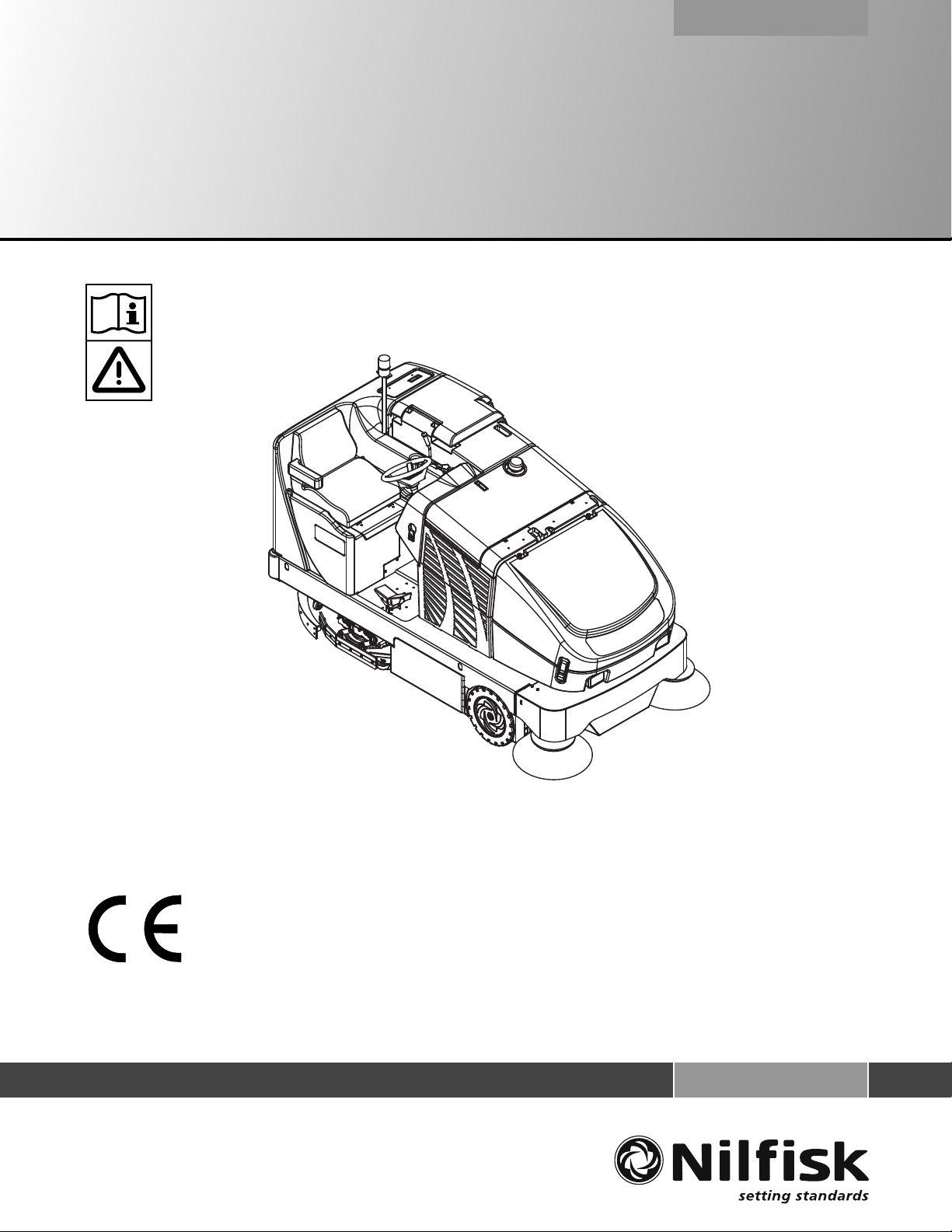
TOWING OR PUSHING A DISABLED MACHINE
CAUTION!
The machine’s drive propelling pump is manufactured with an adjustable tow valve. This valve prevents damage to the hydraulic
system when the machine is being towed/pushed short distances without use of the engine.
To access the valve, open the Engine Compartment Door (22) and lift off the Right Engine Compartment Access Panel (37). Locate the
valve as shown on the underside of the hydrostatic pump by reaching under the radiator. Turn the valve 90 degrees; this disengages the
hydrostatic lock between the motor and pump.
The hydrostatic pump can be damaged if the machine is towed with the valve in the normal working position (A). Reference the illustration
below for the normal working setting (A) and the free wheeling towing setting (B). Note: If the tow valve is left in free wheeling (B) position
the hydrostatic pump can’t drive the machine FWD or REV. No damage will result, just re-set valve to the normal working setting (A). Tow
or push machine no faster than a normal walking pace (2-3 miles per hour) and for short distances only. If the machine is to be moved long
distances the rear drive wheel needs to be raised off the fl oor and placed on a suitable transport dolly.
BOTTOM VIEW OF HYDROSTATIC PUMP

A-8 - FORM NO. 56041797 - CR 1100, 1200, 1400
A-8 / ENGLISH
KNOW YOUR MACHINE
As you read this manual, you will occasionally run across a bold number or letter in parentheses - example: (2). These numbers refer to
an item shown on these pages unless otherwise noted. Refer back to these pages whenever necessary to pinpoint the location of an item
mentioned in the text. NOTE: Refer to the service manual for detailed explanations of each item illustrated on the next 4 pages.
1 Operator’s Seat
2 Strobe Light (optional)
3 Solution Tank Fill
4 Gasoline Tank Cap
5 Fuel Tank
6 Tie Down Locations
7 Recovery Tank Drain Hose
8 Engine Air Filter
9 Left Engine Compartment Access Panel
10 Main Broom Left Access Door
11 Battery
12 Hopper Lid Prop Rod
13 Front Wheel
14 Left Side Broom
15 Hopper Lid Latch
16 Headlights
17 Right Side Broom
18 Hopper Cover
19 Dust Control Filter
20 Dust Control Shaker Assembly

FORM NO. 56041797 - CR 1100, 1200, 1400 - A-9
ENGLISH / A-9
KNOW YOUR MACHINE (CONTINUED)
21 Shaker Assembly Latch
22 Engine Compartment Door
23 Coolant Recovery Tank
24 Steering Wheel
25 Squeegee Handle
26 Squeegee Tool Assembly
27 Tail Light
28 Exhaust Tail Pipe
29 Fuel Tank Compartment Door
30 Recovery Tank Lid
31 Recovery Tank “Tip-Out” Grip
32 Engine Air Filter Hood
33 Radiator Cap
34 Oil Cooler “Tip-Out” Latches
35 Hydraulic “Charge” Oil Filter
36 Hydraulic Reservoir / In Tank Return Oil Filter
37 Right Engine Compartment Access Panel
38 Main Broom Right Access Door
39 Access Door Latch
40 Skirt Assembly
41 Inline Solution Filter
42 Solution Tank Drain Hose
43 Rear Roller Bumper
44 Jacking Location
45 Engine Oil Dipstick
46 Air Filter Service Indicator
47 Fuel Filter (Gas Models)
48 Recovery Tank Latch
49 Hydraulic Reservoir Access Panel
50 Water Level Gauge
51 Operator Seat Adjustment Lever
A-10 - FORM NO. 56041797 - CR 1100, 1200, 1400
A-10 / ENGLISH
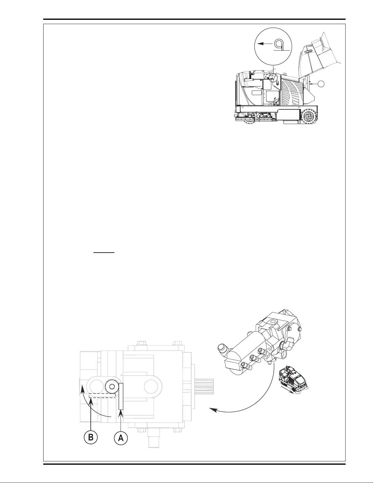
OPERATOR’S COMPARTMENT
A Low Fuel Indicator (LP)
B Horn Switch
* Horn ON Indicator
C Engine Service Indicator (triggered by ECU)
D Headlight Switch
* Headlight ON Indicator
E Glow Plug Indicator (Diesel / Release key after indicator
turns OFF)
F Hydraulic Filter Plugged Indicator
G Engine Speed Switch
* Engine Speed Switch Indicator
H Scrub Pressure Decrease Switch
* Scrub Pressure Decrease Indicator
I Scrub Pressure Increase Switch
* Scrub Pressure Increase Indicator
J Scrub Pressure Display
K Solution Switch
* Solution System Indicator
L Solution Tank Empty Indicator
M Recovery Tank Full Indicator
N Side Broom DOWN/ON Switch
* Side Broom ON Indicator
O Main Broom ON Indicator
FORM NO. 56041797 - CR 1100, 1200, 1400 - A-11
ENGLISH / A-11
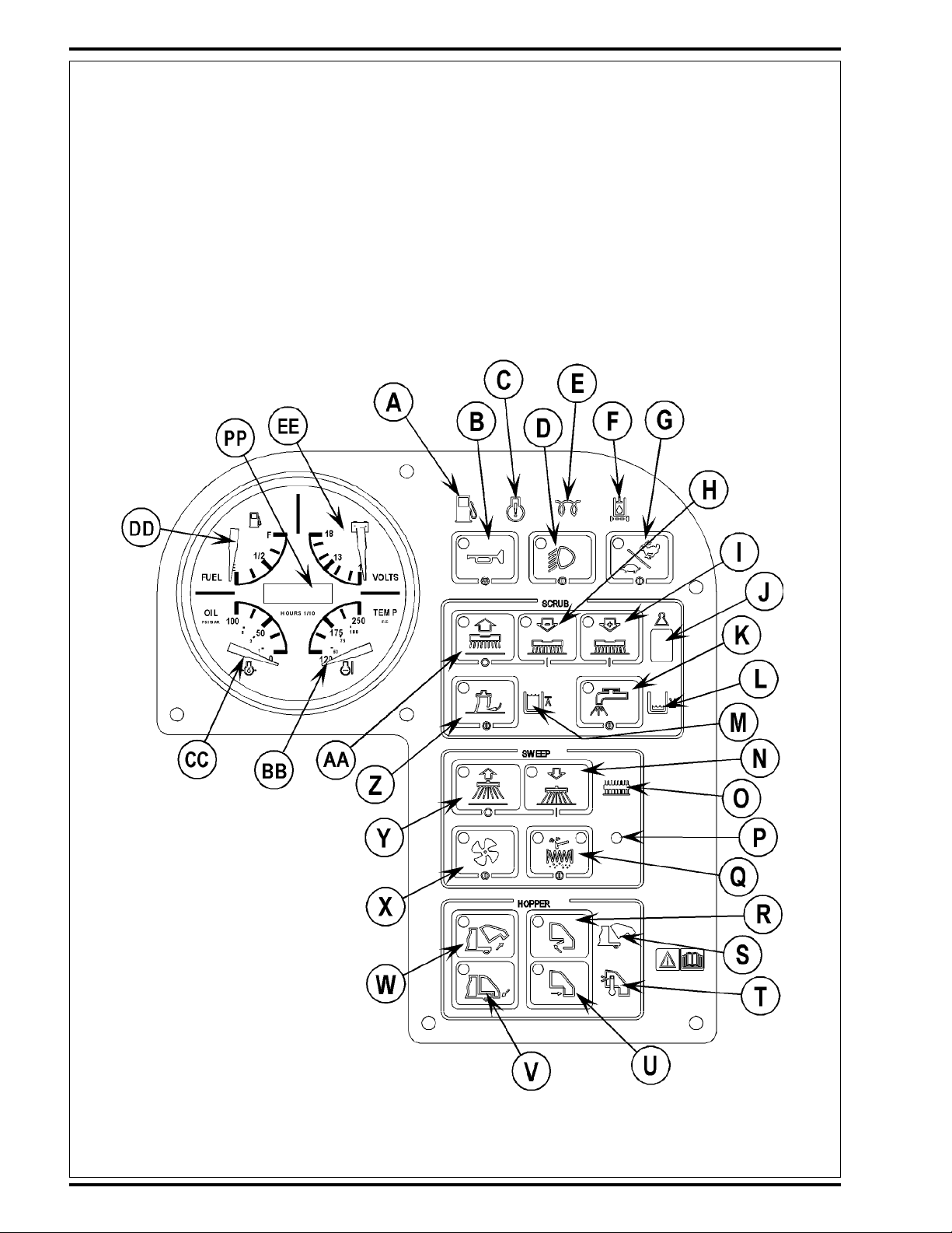
OPERATOR’S COMPARTMENT (CONTINUED)
P Light Sensor
Q Shaker Switch
* Shaker Indicator (left)
* Dust Filter Plugged Indicator (right)
R Open Dump Door Switch
* Open Dump Door Indicator
S Hopper Open Indicator
T Hopper Overtemp Indicator
U Close Dump Door Switch
* Close Dump Door Indicator
V Lower Hopper Switch
* Lower Hopper Indicator
W Raise Hopper Switch
* Raise Hopper Indicator
X Dust Control Switch
* Dust Control ON Indicator
Y Side Broom UP/OFF Switch
* Side Broom OFF Indicator
Z Vacuum System Switch
* Vacuum System Indicator
AA Scrub System OFF Switch
* Scrub System OFF Indicator
BB Coolant Temperature Gauge
CC Oil Pressure Gauge
DD Fuel Gauge (Gas / Diesel)
EE Voltmeter
FF Brake Pedal
GG Parking Brake Latch
HH Solution Flow Control Lever
II Main Broom Raise/Lower (ON/OFF) Lever
JJ Main Broom Adjust Knob
KK Hopper Safety Support Lever
LL Control Panel
MM Ignition Switch
NN Tilt Wheel Lever
OO Drive Pedal
PP Hour meter
QQ Main Broom Overload Indicator Light

A-12 - FORM NO. 56041797 - CR 1100, 1200, 1400
A-12 / ENGLISH
FIGURE 1
PRE-OPERATIONAL CHECKLIST
Before Each Use:
* Inspect the machine for damage, oil or coolant leaks.
* Squeeze the rubber dust cup on the Engine Air Filter (8) to release built-up dust.
* Check the engine coolant level (23).
* Check the engine oil level (45).
* Check the hydraulic oil level (36).
* Check the Fuel Gauge (DD) on the gasoline, and diesel models.
* Check the Fuel Gauge located on the LP tank (5) for propane model.
* Check the Air Filter Service Indicator (46).
In the Driver’s Seat:
* Be sure that you understand the operating controls and their functions.
* Adjust the seat to allow easy reach of all controls.
* Insert the Master Key and turn the Ignition Key Switch (MM) to the ON position. Check for proper operation of the Horn (B), Hour Meter
(PP) and Headlights (D). Turn the Ignition Key Switch (MM) OFF.
* Check the Parking Brake Latch (GG). The latch must hold its (locked parked) setting fi rmly with out easily being released.
(Report all defects immediately to service personnel).
Plan Your Cleaning in Advance:
* Arrange long runs with a minimum of stopping or starting.
* Allow 6 inches of broom path overlap to ensure complete coverage.
* Avoid making sharp turns, bumping into posts, or scraping the side of the machine.
MAIN BROOM
Several different main brooms are available for this machine. Contact your Nilfi sk dealer if you need help selecting the best broom for the
surface and litter that you will be sweeping. Note: Reference broom maintenance for installation steps.
SCRUB BRUSHES
1 Remove side skirt assemblies for easier access. NOTE: Loosen large black knob at the front of each skirt mounting bracket, slide the
skirt assembly forward and lift straight UP and off scrub deck.
2 See Figure 1. Make sure that the Lug Locking Latch is in the Unlatched Position (A).
3 Slide the scrub brush under the Brush Mounting Plate (B) and lift it so that the lugs (C) on the brush block pass through the holes in the
plate.
4 Rotate the brush into the Installed Position (D) according to rotation directions shown in fi gure 2 and then rotate the locking latch back
into the Latched Position (E).
TOP VIEW OF BRUSH MOUNTING PLATE

FORM NO. 56041797 - CR 1100, 1200, 1400 - A-13
ENGLISH / A-13
FIGURE 2
TOP VIEW OF SCRUB DECKS SHOWING DIRECTION TO ROTATE
BRUSHES WHILE INSTALLING FOR EACH BRUSH MOTOR
CR 1100, 1200
CR 1400

A-14 - FORM NO. 56041797 - CR 1100, 1200, 1400
A-14 / ENGLISH
FILLING THE SOLUTION TANK
The solution tank fi ll (3) is located at the left rear corner of the machine and has
a 75 gallon (284 liter) capacity. Fill the tank with the proper dilution of cleaning
chemical mixed with water according to the manufacturer’s recommendations.
If using a powdered chemical, mix it with water in a bucket before putting it into
the machine’s solution tank. NOTE: DO NOT fi ll the tank past the Maximum
Level on the Water Level Gauge (50). NOTE: EDS machines can either be used
conventionally with detergent mixed in the tank or the EDS detergent dispensing
system can be used. When using the EDS detergent dispensing do not mix
detergent in the tank, plain water should be used.
CAUTION!
Use only low-sudsing, non-fl ammable, non-caustic cleaning chemicals
intended for machine application.
FUEL
WARNING!
• ALWAYS STOP THE ENGINE BEFORE FILLING THE FUEL TANK.
• DO NOT SMOKE WHILE FILLING THE FUEL TANK.
• FILL THE FUEL TANK IN A WELL-VENTILATED AREA.
• DO NOT FILL THE FUEL TANK NEAR SPARKS OR OPEN FLAME.
• USE ONLY THE FUEL SPECIFIED ON THE FUEL TANK DECAL.
On machines with diesel and gasoline engines, a decal near the fi ller neck (4) shows the proper fuel to use in the machine. Before removing
the cap from the tank, wipe all dust and dirt from the cap and from the top of the tank to keep the fuel as clean as possible.
On machines with propane engines, a decal near the tank gives specifi c information about the proper type of tank to be used on the machine.
DIESEL ENGINE
Fill the tank with Number 2 Diesel Fuel if the machine will be used in an area where the temperature is 30° Fahrenheit (0° Celsius) or higher.
Use Number 1 Diesel Fuel if the machine will be used in an area where the temperature is below 30° Fahrenheit (0° Celsius).
NOTE: If the diesel machine runs out of fuel completely, the fuel system must be bled before the engine can be re-started. To avoid this
situation, fi ll the fuel tank when the fuel gauge indicates 1/4 tank. Fuel tank capacity is 11 gallons (42 liters).
GASOLINE ENGINE
FILL THE TANK WITH UNLEADED 87 OCTANE REGULAR GASOLINE. FUEL TANK CAPACITY IS 11 GALLONS (42 LITERS).
Note: Reference the separately supplied engine manufacture’s maintenance and operator manual for more detailed engine specifi cation and
service data.
PROPANE ENGINE
Mount a standard 33 lb. liquid withdrawal propane tank on the machine, connect the fuel hose and open the shutoff valve on the tank. Wear
gloves when connecting or disconnecting the fuel hose. Shut the propane tank service valve OFF when the machine is not in use.

FORM NO. 56041797 - CR 1100, 1200, 1400 - A-15
ENGLISH / A-15

A-16 - FORM NO. 56041797 - CR 1100, 1200, 1400
A-16 / ENGLISH
DETERGENT SYSTEM PREPARATION AND USE (EDS MODELS ONLY)
Fill the detergent cartridge with a maximum of 2.2 gallons (8.32 Liters) of detergent. SERVICE NOTE: Remove the detergent cartridge from the detergent box prior to fi lling to
avoid spilling detergent on the machine.
It is recommended that a separate cartridge be used for each detergent you plan to use. The detergent cartridges have a white decal on them so you can write the detergent
name on each cartridge to avoid mixing them up. The detergent cartridge has a Magnetic Slider (A) on one end that should be set to the proper dilution ratio according to the
dilution instructions on the manufacturer’s bottle. Slide the Magnet Slider (A) to the appropriate location on Detergent Dilution Ratio Decal (B). When installing a new cartridge,
remove the Cap (C) and place the cartridge in the detergent box. Install the Dry Break Cap (D) as shown.
The system should be purged of previous detergent when switching to a different detergent. SERVICE NOTE: Move machine over fl oor drain before purging because a small
amount of detergent will be dispensed in the process.
To Purge When Changing Chemicals:
1 Disconnect and remove the detergent cartridge.
2 Turn the Key Switch (MM) ON and press the Detergent ON/OFF Switch (RR) for at least 2 seconds. NOTE: Once activated the purge process takes about 10 seconds.
See illustration on next page for Detergent System indicators. Normally one purge cycle is adequate to purge the system.
To Purge Weekly:
1 Disconnect and remove the detergent cartridge. Install and connect a Cartridge fi lled with clean water
2 Turn the Key Switch (MM) ON and press the Detergent ON/OFF Switch (RR) for at least 2 seconds. NOTE: Once activated the purge process takes about 10 seconds.
See illustration on next page for Detergent System indicators. Normally one purge cycle is adequate to purge the system.
The Detergent Box (E) has a Detergent Level Viewing Slot (F) for keeping track of how much detergent is remaining in the cartridge. When the detergent level is nearing the
bottom of this slot it is time to refi ll or replace the cartridge.
General Use:
The detergent (EDS) system is enabled when the Key Switch (MM) is turned on and reverts to the last state (Chem On or Chem Off) it was in prior to the last power down.
The current Solution Flow Rate (VV) and the last used Detergent Ratio (WW) (if in “Chem On” state) are displayed. The Status LED (YY) indicates the status of the system as
follows:
GREEN: Solution not low and chemical pump ON (pumping solution and chemical)
BLINKING GREEN: Purge has been activated
LED OFF: Solution fl ow position = 0 or solution solenoid is OFF
ORANGE: Solution ON and Chemical OFF (pumping solution only)
BLINKING RED: Solution low and chemical pump ON (pumping solution only)
No detergent is dispensed until the scrub system is activated and the Drive Pedal (OO) pushed forward. The detergent ratio can be varied by subsequently pressing the
Detergent Increment and Decrement Switches (SS & TT). The detergent fl ow rate increases or decreases with the solution fl ow rate but the detergent ratio remains the same
unless changed. During scrubbing, the detergent system can be turned off at any time by pressing the Detergent ON/OFF Switch (RR) to allow scrubbing with water only. On
EDS models the solution fl ow rate (40%-100%) is electronically controlled and is displayed (VV) on the EDS display panel as shown below.
SERVICE NOTE: Follow the “To Purge Weekly” instructions above if the machine is going to be stored for an extended period of time or if you plan to discontinue use of the
detergent (EDS) system. The Display Panel (UU) will display an Error Code “E1” (XX) in the lower left corner if the magnetic slider circuit board (ZZ) becomes disconnected or
malfunctions.

FORM NO. 56041797 - CR 1100, 1200, 1400 - A-17
ENGLISH / A-17
DETERGENT SYSTEM PREPARATION AND USE (EDS MODELS ONLY)

A-18 - FORM NO. 56041797 - CR 1100, 1200, 1400
A-18 / ENGLISH
OPERATING THE MACHINE
The CR 1100-1400™ is a rider-type automatic fl oor sweeping and scrubbing machine. It is designed to sweep up debris, lay down cleaning
solution, scrub the fl oor, and vacuum dry all in one pass. The sweeping and scrubbing operations can also be performed separately.
The controls on the CR 1100-1400 were designed with one touch operation in mind. For single pass scrubbing the user can simply depress
one switch and all scrub functions on the machine will be ready to go. For sweeping, the operator can simply lower the main broom and all
sweeping functions will be ready to go.
Note: Bold numbers in parentheses indicate an item illustrated on pages 6-9.
BEFORE STARTING THE MACHINE
1 Be sure you understand all machine controls and their functions.
2 Plan your cleaning route. Arrange long, straight passes with as few turns as possible.
3 Check the Brake Pedal (FF). The pedal should be fi rm.
If the pedal is “spongy” or fades under pressure, DO NOT DRIVE THE MACHINE. Report all defects immediately to service personnel.
STARTING THE DIESEL ENGINE
1 Turn the Key Switch (MM) counter-clockwise to the “Pre-Heat” position and hold it there until the Glow Plug Indicator (E) turns OFF.
Once the indicator turns OFF the engine can be started. Skip this step if the engine has been running and is already warm.
2 Turn the Key Ignition Switch (MM) clockwise to the START position and release it as soon as the engine starts. If the engine does not
start after cranking for 15 seconds, release the key, wait for 1 minute and try steps 1-3 again.
3 Let the engine run at “IDLE” speed for 5 minutes before using the machine.
4 Push the Engine Speed Switch (G) to switch to “FULL THROTTLE” and move the machine around for 2 or 3 minutes at a slow speed to
warm up the hydraulic system.
STARTING THE GASOLINE ENGINE
1 Turn the Ignition Key Switch (MM) clockwise to the START position and release it as soon as the engine starts. If the engine does not
start after cranking for 15 seconds, release the key, wait for 1 minute, then try again.
2 Let the engine run at “IDLE” speed for 5 minutes before using the machine.
3 Push the Engine Speed Switch (G) to switch to “FULL THROTTLE” and move the machine around for 2 or 3 minutes at a slow speed to
warm up the hydraulic system.
STARTING THE PROPANE ENGINE
1 Open the service valve on the LP fuel tank (5).
2 Turn the Ignition Key Switch (MM) clockwise to the START position and release it as soon as the engine starts. If the engine does not
start after cranking for 15 seconds, release the key, wait for 1 minute, then try again.
3 Let the engine run at “IDLE” speed for 5 minutes before using the machine.
4 Push the Engine Speed Switch (G) to switch to “FULL THROTTLE” and move the machine around for 2 or 3 minutes at a slow speed to
warm up the hydraulic system.
ALWAYS operate the machine with the Engine Speed Switch at full throttle. Use the Drive Pedal (OO) not the Engine Speed Switch
(G) to control the speed of the machine. The speed of the machine will increase as the pedal is pushed closer to the fl oor. Do not press the
Drive Pedal (OO) until the engine has started.
IMPORTANT NOTE: During normal operation the engine will continue to run for a short period of time (1-3 seconds) after turning the key
OFF until all fuel is dispelled from fuel system.

FORM NO. 56041797 - CR 1100, 1200, 1400 - A-19
ENGLISH / A-19
SWEEPING
Follow the instructions in preparing the machine for use section of this manual.
1 While seated on the machine, adjust the seat and steering wheel to a comfortable operating position using the adjustment controls (51)
and (NN).
2 Release the Parking Brake (GG). To transport the machine to the work area, apply even pressure with your foot on the front of the Drive
Pedal (OO) to go forward or the rear of the pedal for reverse. Vary the pressure on the foot pedal to obtain the desired speed.
3 Push the Lower Hopper Switch (V) to make sure the hopper is seated properly.
4 Move the Main Broom Lever (II) to the SWEEP (middle notch) position to lower and enable the main broom. NOTE: The dump door
opens automatically when the main broom (II) is lowered and closes when the broom is raised.
Use the FULL FLOAT (last notch forward) position only when sweeping extremely rough or uneven fl oors. Use at other times will only
increase broom wear.
5 When sweeping dry fl oors, push the Dust Control Switch (X) to turn ON the dust control system.
When sweeping fl oors with puddles, push the Dust Control Switch (X) to turn OFF the dust control system before the machine enters a
puddle. Turn the dust control system back ON when the machine is back on completely dry fl oor.
When sweeping wet fl oors, keep the Dust Control Switch (X) OFF at all times.
6 Lower the Side Broom(s) (N) when sweeping along walls or curbs. Raise the Side Broom(s) (Y) when sweeping in open areas. Push
and hold the Side Broom ON/DOWN Switch (N) to lower and start the side broom motor(s). NOTE: Hold the switch until the side
broom(s) have lowered to the desired level. Side broom sweeping pattern is adjusted by pushing switches (N & Y) until the desired
amount of down pressure is achieved. NOTE: If the side broom(s) were not raised and turned OFF after last use, they will automatically
lower and turn ON when the main broom is lowered and starts.
7 Drive the machine straight forward at a quick walking speed. Drive the machine slower when sweeping large amounts of dust or debris
or when safe operation dictates slower speeds. Overlap passes 6 inches (15 cm).
8 If dust comes out of the broom housing while sweeping, the Dust Control Filter (19) may be clogged. Push the Shaker Switch (Q) to
clean the dust control fi lter. The dust control system (X) will automatically turn OFF while the shaker is running and turn ON after the
shaker turns OFF (the shaker runs for 20 seconds).
9 Check behind the machine occasionally to make sure that the machine is picking up debris. Dirt left behind in the path of the machine
usually indicates that the machine is moving too fast, the broom needs to be adjusted, or the hopper is full.
EMPTYING THE HOPPER
1 Push the Shaker Switch (Q) to remove excess dirt from the dust control fi lter. SERVICE NOTE: For best shaker performance always
run the shaker with the hopper fully down.
2 Drive the machine close to a large trash receptacle and hold the Raise Hopper Switch (W) until the hopper is all the way up. NOTE:
The dump door automatically closes when switch (W) is pushed. You regain control of the dump door as soon as the hopper begins to
raise so you can dump at any height if necessary.
3 Move the machine forward until the hopper is over the receptacle, then press the Open Dump Door Switch (R) to open the dump door
and empty the hopper.
4 Check the back of the hopper and the front of the broom housing. Use a broom, if necessary, to remove litter from these areas. The
back of the hopper must seal tightly against the front of the broom housing for proper operation.
5 Back the machine away from the receptacle until the hopper will clear it, and then lower the hopper (V). NOTE: The dump door will
automatically open when sweep function is resumed.

A-20 - FORM NO. 56041797 - CR 1100, 1200, 1400
A-20 / ENGLISH
SCRUBBING
Follow the instructions in preparing the machine for use section of this manual.
1 While seated on the machine, adjust the seat and steering wheel to a comfortable operating position using the adjustment controls (51)
and (NN).
2 Release the Parking Brake (GG). To transport the machine to the work area, apply even pressure with your foot on the front of the Drive
Pedal (OO) to go forward or the rear of the pedal for reverse. Vary the pressure on the foot pedal to obtain the desired speed.
3 Adjust the Solution Flow Control Lever (HH) to about 1/4 to 1/3 open (40%-100% on EDS) position. The adjustment can be changed to
allow variable solution fl ow for different types of fl oors to be scrubbed. Example: A rough or absorbent fl oor surface, such as unfi nished
concrete will require more solution than a smooth fi nished fl oor .
4 Press the Solution Switch (K) and hold for 5 seconds. This is done to pre-wet the fl oor. Note: This will help prevent scarring of the fl oor
surface when starting to scrub with dry brushes.
5 Press the Scrub Pressure Decrease Switch (H) or the Scrub Pressure Increase Switch (I) to activate the scrub system.
6 When the Scrub Pressure Decrease Switch (H) or the Scrub Pressure Increase Switch (I) are selected, the brushes and squeegee are
automatically lowered to the fl oor. The machine’s scrub brush rotation, solution system fl ow, detergent fl ow (EDS only) and vacuum
starts when the Drive Pedal (OO) is activated. Note: When operating the machine in reverse, only the brushes will rotate, the solution
and detergent (EDS only) is automatically shut off and the squeegee raises.
7 Begin scrubbing by driving the machine forward in a straight line at a normal walking speed and overlap each path by 2-3 inches (50-75
mm). Adjust the machine speed and solution fl ow according to the condition of the fl oor.
CAUTION!
To avoid damaging the fl oor, keep the machine moving while the brushes are turning.
8 When scrubbing, check behind the machine occasionally to see that all of the waste water is being picked up. If there is water trailing
the machine, you may be dispensing too much solution, the recovery tank may be full, or the squeegee tool may require adjustment.
9 For extremely dirty fl oors, a one-pass scrubbing operation may not be satisfactory and a “double-scrub” operation may be required. This
operation is the same as a one-pass scrubbing except on the fi rst pass the squeegee is in the up position (press the Vacuum Switch (Z)
to raise the squeegee). This allows the cleaning solution to remain on the fl oor to work longer. The fi nal pass is made over the same
area, with the squeegee lowered to pick up the accumulated solution.
10 The recovery tank has an automatic vacuum shut-off to prevent solution from entering the vacuum system when the recovery tank is full.
When the vacuum shut-off is activated, the control system will shut down the vacuum system. The Recovery Tank FULL Indicator (M) will
light. When the vacuum shut-off is activated, the recovery tank must be emptied.
11 When the operator wants to stop scrubbing or the recovery tank is full, press the Scrub System OFF Switch (AA) once. This will
automatically stop the scrub brushes, solution fl ow, detergent fl ow(EDS only) and the scrub deck will raise UP. NOTE: the vacuum/
squeegee system will not be turned off when the switch is only pressed once. This is to allow any remaining water to be picked up
without turning the vacuum back on. Press the switch a second time and the squeegee will raise and the vacuum will stop after a 10
second delay.
12 Drive the machine to a designated waste water “DISPOSAL SITE” and empty the recovery tank. To empty, pull the Drain Hose (7) from
its storage area and then remove the plug (hold the end of the hose above the water level in the tank to avoid sudden, uncontrolled fl ow
of waste water). Refi ll the solution tank and continue scrubbing.
SERVICE NOTE: Refer to the service manual for detailed functional descriptions of all controls and optional programmability.

FORM NO. 56041797 - CR 1100, 1200, 1400 - A-21
ENGLISH / A-21
EMPTYING THE RECOVERY TANK
1 Drive the machine to a designated waste water “DISPOSAL SITE”.
2 To empty, pull the Drain Hose (7) from its storage area, then remove the plug (hold the end of the hose above the water level in the tank
to avoid sudden, uncontrolled fl ow of waste water).
3 Flush the tank and drain hose with clean water.
4 Put the plug back into the hose and return the hose to its storage area.
SERVICE NOTE: The recovery tank can be tipped out to the side for cleaning after emptying. Release the Latch (48) at the front of the tank
next to the engine air fi lter (8) and then pull out on the tank with grip (31) until the tank reaches the end of its tether. Remove the recovery
tank lid for easier cleaning.
AFTER USE
1 Raise the squeegee, the scrub brushes, and the brooms.
2 Shake the dust control fi lter and empty the hopper.
3 Drain and fl ush the recovery tank.
4 Flush the vacuum hose and squeegee by opening the recovery tank lid and running water down the pickup tube on the right side of the
tank. SERVICE NOTE: Tip the recovery tank out and check the squeegee hose elbow below the tank to make sure it has fl ushed out
completely.
5 Remove and clean the squeegee tool.
6 Remove and clean the scrub brushes. Rotate the scrub brushes.
7 Wipe the machine with a damp cloth.
8 Perform all required maintenance before storage.
9 Move the machine to a clean, dry storage area.
10 Store the machine with the brooms, the squeegee and the scrub brushes in the UP position, and the tank covers open so that the tanks
can air out.
REPORT ANY DEFECT OR MALFUNCTION NOTED DURING OPERATION TO AUTHORIZED SERVICE OR MAINTENANCE
PERSONNEL.
SHUTTING DOWN THE DIESEL / GASOLINE ENGINE
1 Put all controls to the OFF position.
2 Raise the squeegee, the scrub brushes, and the brooms.
3 Push the Engine Speed Switch (G) to change to “Idle” speed and let the engine idle for 30 seconds.
4 Apply the Parking Brake (GG).
5 Turn the Key Ignition Switch (MM) OFF and remove the key.
SHUTTING DOWN THE PROPANE ENGINE
1 Put all controls to the OFF position.
2 Raise the squeegee, the scrub brushes, and the brooms.
3 Turn the service valve on LP gas tank OFF.
4 Push the Engine Speed Switch (G) to change to “Idle” speed and let the engine idle until all the LP gas is dispelled from the line.
5 Apply the Parking Brake (GG).
6 Turn the Key Ignition Switch (MM) OFF and remove the key.
CHECK THE HYDRAULIC OIL LEVEL
WARNING!
To avoid hydraulic oil injection or injury, always wear appropriate clothing and eye protection when working with or near hydraulic
system.
See Figure 3. Remove the Right Engine Access Panel (37) and look at the Gauge (A) on the side of the reservoir. If the oil level is
below the minimum level, add 10W30 motor oil until the gauge reads between the minimum and maximum levels. Change the oil if
major contamination from a mechanical failure occurs. SERVICE NOTE: Remove the small access panel (49) directly above the
reservoir to add oil. This panel is held on by (2) wing nuts on the underside of the panel. The large Allan Head Plug (B) on the top of
the reservoir is for adding oil.
IMPORTANT!
This machine is equipped with an Indicator Light (F) which lights if the “In Tank” oil fi lter requires changing. Remove fi lter
element from the fi lter cup (C) and replace with new fi lter. Hydraulic fi lter is found on top of the Hydraulic Reservoir (36) as
shown.
 Loading...