


Advolution™ 2710
UHR 70-1700
Service Manual
Advance Models: 56422000, 56422002
Nilfisk Model: 56422001
7/06 revised 6/08 FORM NO. 56043107

TABLE OF CONTENTS |
|
INTRODUCTION ................................................................................................................. |
4 |
IMPORTANT SAFETY INSTRUCTIONS ............................................................................. |
5 |
TECHNICAL SPECIFICATIONS.......................................................................................... |
6 |
MAINTENANCE SCHEDULE .............................................................................................. |
8 |
KNOW YOUR MACHINE.............................................................................................. |
10-11 |
FUNCTIONAL DESCRIPTION OF CONTROL BUTTONS:............................................... |
12 |
BURNISHING SYSTEM .................................................................................................... |
13 |
FUNCTIONAL OVERVIEW ........................................................................................ |
13 |
PAD LIFT ACTUATOR REMOVAL AND INSTALLATION ........................................... |
14 |
PAD DRIVE DECK REMOVAL ................................................................................... |
14 |
PAD DRIVE MOTOR CARBON BRUSH INSPECTION ............................................. |
14 |
PAD DRIVE MOTOR REMOVAL................................................................................ |
15 |
DUST SHROUD REMOVAL ....................................................................................... |
15 |
DUST SHROUD EDGING REPLACEMENT .............................................................. |
16 |
PAD DRIVE DECK LEVEL ADJUSTMENT................................................................. |
17 |
PAD DRIVE DECK LEVEL ADJUSTMENT................................................................. |
18 |
INSTALLATION OF THE BURNISHING PAD............................................................. |
19 |
INSTALLATION OF THE DUST COLLECTION BAG ................................................. |
20 |
TROUBLESHOOTING GUIDE ELECTRICAL............................................................ |
21 |
WHEEL DRIVE SYSTEM .................................................................................................. |
25 |
GENERAL FUNCTIONAL OVERVIEW ...................................................................... |
25 |
DRIVE MOTOR SYSTEM CONTROLLER FUNCTION OVERVIEW ......................... |
25 |
DRIVE MODE SELECTION OPERATION OVERVIEW ............................................. |
25 |
WHEEL DRIVE TROUBLESHOOTING GUIDE ......................................................... |
28 |
WHEEL DRIVE ASSEMBLY REMOVAL..................................................................... |
30 |
WHEEL DRIVE MOTOR REMOVAL .......................................................................... |
31 |
DRIVE WHEEL REMOVAL......................................................................................... |
32 |
ELECTROMAGNETIC BRAKE ASSEMBLY REMOVAL ............................................ |
33 |
STEERING CHAIN REMOVAL AND TENSIONING ................................................... |
34 |
POTENTIOMETER REMOVAL AND TESTING.......................................................... |
35 |
POTENTIOMETER INSTALLATION AND ADJUSTMENT:......................................... |
35 |
ALTERNATE METHOD FOR THROTTLE ADJUSTMENT......................................... |
35 |
DRIVE PEDAL NEUTRAL ADJUSTMENT & PEDAL REPLACEMENT ..................... |
37 |
TROUBLESHOOTING GUIDE ELECTRICAL............................................................ |
38 |
2 - FORM NO. 56043107 - Advolution™ 2710 / UHR 70-1700

TABLE OF CONTENTS (CONTINUED) |
|
ELECTRICAL SYSTEM ..................................................................................................... |
40 |
BATTERIES................................................................................................................ |
40 |
CHARGING THE BATTERIES ................................................................................... |
41 |
CHECKING THE BATTERY WATER LEVEL.............................................................. |
41 |
BATTERY MAINTENANCE ........................................................................................ |
41 |
CHARGING THE BATTERIES (CONTINUED)........................................................... |
42 |
BATTERY TESTING................................................................................................... |
42 |
BATTERY SPECIFICATIONS..................................................................................... |
42 |
BATTERY CHARGER SPECIFICATIONS.................................................................. |
42 |
ACTUATOR DRIVE NUT ADJUSTMENT................................................................... |
43 |
CURTIS CONTROLLER DIAGNOSTICS: .................................................................. |
44 |
FUNCTION OF THE SPEED CONTROLLER STATUS LIGHT AND DISPLAY.......... |
44 |
PROGRAMMER DIAGNOSTICS: .............................................................................. |
44 |
DIAGNOSTIC HISTORY ............................................................................................ |
44 |
SPEED CONTROL PROGRAMMING OPTIONS....................................................... |
45 |
INSTALLATION CHECKOUT FOR THE CURTIS SPEED CONTROLLER................ |
47 |
PROGRAMMING VEHICLE SPEED CHANGES ....................................................... |
47 |
FUNCTIONAL OVERVIEW OF MAIN CONTROL BOARD ........................................ |
48 |
MAIN CONTROLLER ERROR CODES ..................................................................... |
48 |
ADVOLUTION PROGRAMMING MODES ................................................................. |
49 |
FAULT RECALL MODE / REVISION DISPLAY: .............................................................................. |
49 |
SERVICE TEST MODE: .................................................................................................................. |
49 |
STATUS DISPLAY: .......................................................................................................................... |
50 |
OUTPUT CONTROLS: .................................................................................................................... |
50 |
HORN SWITCH: .............................................................................................................................. |
50 |
PAD SWITCH:.................................................................................................................................. |
50 |
LOW VOLTAGE CUTOUT THRESHOLD SELECTION MODE: ...................................................... |
51 |
FAULT DETECTION ENABLE/DISABLE MODE: ............................................................................ |
51 |
PAD PRESSURE ADJUSTMENT MODE: ....................................................................................... |
51 |
FORWARD MOTION ALARM VOLUME LEVEL ADJUSTMENT MODE: ........................................ |
52 |
REVERSE MOTION ALARM (BACK-UP ALARM) VOLUME LEVEL ADJUSTMENT MODE:......... |
52 |
BURNISHING SPEED LIMIT ENABLE/DISABLE MODE:............................................................... |
52 |
TROUBLESHOOTING GUIDE .......................................................................................... |
53 |
COMPONENT LOCATION .............................................................................................................. |
55 |
WIRING DIAGRAM / SCHEMATIC............................................................................................. |
56-57 |
Note: All references to right, left, front, or rear in this manual are as seen from the operator’s standpoint. |
|
FORM NO. 56043107 - Advolution™ 2710 / UHR 70-1700 - 3

INTRODUCTION
This manual will help you get the most from your Nilfisk-Advance Advolution™ 2710 / UHR 70-1700. Read it thoroughly before operating the machine.
Note: Bold numbers in parentheses indicate an item illustrated on pages 10 – 11.
This product is intended for commercial use only.
PARTS AND SERVICE
Repairs, when required, should be performed by Nilfisk-Advance service personnel using Nilfisk-Advance original replacement parts and accessories.
Call Nilfisk-Advance for repair parts or service. Please specify the Model and Serial Number when discussing your machine.
NAME PLATE
The Model and Serial Number of your machine are shown on the Nameplate on the machine. This information is needed when ordering repair parts for the machine. Use the space below to note the Model and Serial Number of your machine for future reference.
MODEL ________________________________________________
SERIAL NUMBER ________________________________________
TRANSPORTING THE MACHINE
CAUTION!
Before transporting the machine on an open truck or trailer, make sure that . . .
•The machine is tied down securely.
•All access doors and covers are secured (tape and strap as needed).
TOWING
Reference page 8 for towing instructions.
OTHER MANUALS AVAILABLE FOR YOUR MACHINE
The manuals listed below can be found via Nilfisk-Advance’s two electronic supported databases. They are:
•Nilfisk-Advance Dealer Customer Zone
•Ezparts service / parts CD-Rom
•Parts List - Form Number 56042468
• |
Instructions for Use - Form Number |
56041634 (English, Spanish) |
|
|
|
56041635 |
(Danish, Norwegian, Swedish, Finnish) |
|
|
56041636 |
(German, French, Dutch, Russian) |
|
|
56041637 |
(Spanish, Portuguese, Italian, Greek) |
|
|
56041638 |
(Estonian, Latvian, Lithuanian, Slovenian) |
|
|
56041639 |
(Slovakian, Czech, Polish, Hungarian) |
|
|
56041655 |
(Turkish) |
4 - FORM NO. 56043107 - Advolution™ 2710 / UHR 70-1700

IMPORTANT SAFETY INSTRUCTIONS
This machine is only suitable for commercial use, for example in hotels, schools, hospitals, factories, shops and offices other than normal residential housekeeping purposes.
Read all instructions before using.
WARNING!
To reduce risk of fire, electric shock, or injury:
•Use only as described in this manual. Use only manufacturer’s recommended attachments.
•This machine shall be used only by properly trained and authorized persons.
•This machine is for dry use only and shall not be used or stored outdoors in wet conditions.
•Do not allow to be used as a toy. Close attention is necessary when used by or near children.
•Keep sparks, flame and smoking materials away from batteries. Explosive gases are vented during normal operation.
•Charging the batteries produces highly explosive hydrogen gas. Charge batteries with seat cover open in well-ventilated areas, away from open flame. Do not smoke while charging the batteries.
•Remove all jewelry when working near electrical components.
•Turn the key switch off (O) and disconnect the batteries before servicing electrical components.
•Never work under a machine without safety blocks or stands to support the machine.
•Do not dispense flammable cleaning agents, operate the machine on or near these agents, or operate in areas where flammable liquids exist.
•Do not clean this machine with a pressure washer.
•This machine is not approved for use on public paths or roads.
•Do not put any object into openings. Do not use with any opening blocked; keep free of dust, lint, hair, and anything that may reduce air flow.
•Do not use on surfaces having a gradient exceeding that marked on the machine.
•When operating this machine, ensure that third parties, particularly children, are not endangered.
•Before performing any service function, carefully read all instructions pertaining to that function.
•Do not leave the machine unattended without first turning the key switch off (O) and removing the key. The parking brake is automatically activated at this time.
•Turn the key switch off (O) and remove the key, before changing the brushes, and before opening any access panels.
•Take precautions to prevent hair, jewelry, or loose clothing from becoming caught in moving parts.
•Do not use without dust bag and / or filters in place.
•Do not stand on the pad housing.
•This machine is not suitable for picking up health endangering dust.
•The batteries must be removed from the machine before the machine is scrapped. The disposal of the batteries should be safely done in accordance with your local environmental regulations.
•All doors and covers are to be positioned as indicated in the instruction manual before using the machine.
•Refer to the battery charger OEM product manual for additional specific battery charger warnings.
SAVE THESE INSTRUCTIONS
FORM NO. 56043107 - Advolution™ 2710 / UHR 70-1700 - 5

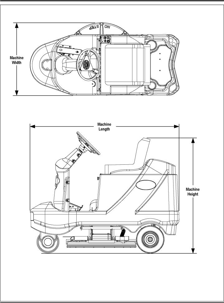
TECHNICAL SPECIFICATIONS
General Specifications |
English (Metric) |
|
Burnishing Pad Diameter |
27 inches (68.58 cm) |
|
|
|
|
Machine Length |
65.5 inches (166.37 cm) |
|
|
|
|
Machine Width |
32 inches (81.28 cm) |
|
|
|
|
Machine Height |
54 inches (137.16 cm) |
|
|
|
|
Machine Weight |
484 lbs. (219.53 kg) net w/o batteries |
|
|
||
1,379 lbs. (626 kg) gross w/six 395 AH batteries |
||
|
||
|
|
|
Front Wheel Weight (w/six 395 AH batteries) |
308 lbs. (139.7 kg) |
|
|
|
|
Rear Right Wheel Weight (w/six 395 AH batteries) |
445 lbs. (201.8 kg) |
|
|
|
|
Rear Left Wheel Weight (w/six 395 AH batteries) |
451 lbs. (204.5 kg) |
|
|
|
|
Front Wheel Pressure (w/six 395 AH batteries) |
128 PSI |
|
|
|
|
Rear Right Wheel Pressure (w/six 395 AH batteries) |
72 PSI |
|
|
|
|
Rear Left Wheel Pressure (w/six 395 AH batteries) |
105 PSI |
|
|
|
|
Average Coverage Rate |
41,580 sq. ft (3,862m2) per hour |
|
Average Run Time |
3 hours per battery charge |
|
|
|
|
Batteries Recommended |
Six 6 volt, 395 A/H @ 20 hour rate, |
|
|
|
|
|
120 lbs. (54.4 kg) each |
|
|
|
|
|
25 inches (63.50 cm) long |
|
|
|
|
Battery Compartment Size |
22.5 inches (57.15 cm) wide |
|
|
|
|
|
17.50 inches (44.45 cm) high |
|
|
|
|
Battery Charger Recommendation |
25 or 36 Amp output, 36 volt charger |
|
|
|
|
Burnisher Pad Motor |
36 volt, 3.25 hp, 85 Amp |
|
|
|
|
Wheel Drive Motor |
36 volt, 1 hp, 27 Amp |
|
|
|
|
Pad Lift Motor |
36 volt, 1/6 hp, 6.7 Amp |
|
|
|
|
Drive System Speed Control |
Electronic, fully variable Fwd/Rev |
|
|
|
|
Max Transport Speed |
396 FT/min |
|
|
|
|
Max Burnish Speed |
308 FT/min |
|
|
|
|
Turning Radius |
72 inches (182.88 cm) |
|
|
|
|
Wheels |
9.75 inch (24.76 cm) drive wheel |
|
|
||
12 inch (30.48 cm) rear wheels |
||
|
||
|
|
|
Ramp Climbing Ability |
12.3% grade |
|
|
|
|
Sound Pressure Level (IEC 60704-1) |
69 dB(A)/20μPa (at operator’s ear) |
|
|
|
6 - FORM NO. 56043107 - Advolution™ 2710 / UHR 70-1700
TECHNICAL SPECIFICATIONS
FORM NO. 56043107 - Advolution™ 2710 / UHR 70-1700 - 7
MAINTENANCE SCHEDULE
MAINTENANCE ITEM |
Daily |
Weekly |
Monthly |
Yearly |
Charge Batteries |
X |
|
|
|
Check/Clean/Replace Burnishing Pad |
X |
|
|
|
Check/Replace Dust Collection Bag |
X |
|
|
|
Check Battery Water Level(s) |
|
X |
|
|
Check/Replace Pad Shroud Skirt |
|
X |
|
|
Chain Tension - Steering |
|
|
X |
|
Lubrication - Grease Fittings |
|
|
X |
|
Check Carbon Brush Wear On Pad/Drive/Vacuum Motors |
|
|
|
X |
Note: See the individual machine system sections for maintenance information.
* Have Nilfisk-Advance check the vacuum motor carbon motor brushes once a year or after 300 operating hours. The pad and drive motor carbon brushes check every 500 hours or once a year.
WARNING!
Turn the key switch off and disconnect the batteries before servicing the machine.
*Check vacuum motor carbon brushes (Qty 2) once a year or after 300 operating hours.
*Check pad and wheel drive motor(s) carbon brushes (Qty 4 per motor) once a year or after 500 operating hours.
*The original (new) length of each carbon brush is 1-3/32” (27.76mm) on all 36 volt machine models brush and wheel drive motors.
*All motors: Replace carbon brushes when shorter than 3/8” (9.5mm) to obtain the same motor efficiency as new brushes.
IMPORTANT!
Motor damage resulting from failure to service the carbon brushes is not covered under warranty. See the Limited Warranty Statement.
BATTERIES AND CHARGERS
Attention: See the ELECTRICAL SYSTEM section for battery installation, battery maintenance and charger system requirements.
LUBRICATING THE MACHINE
Locations requiring periodic oiling are:
Qty 1 - Steering Wheel Shaft Universal Joint (oil hole or port)
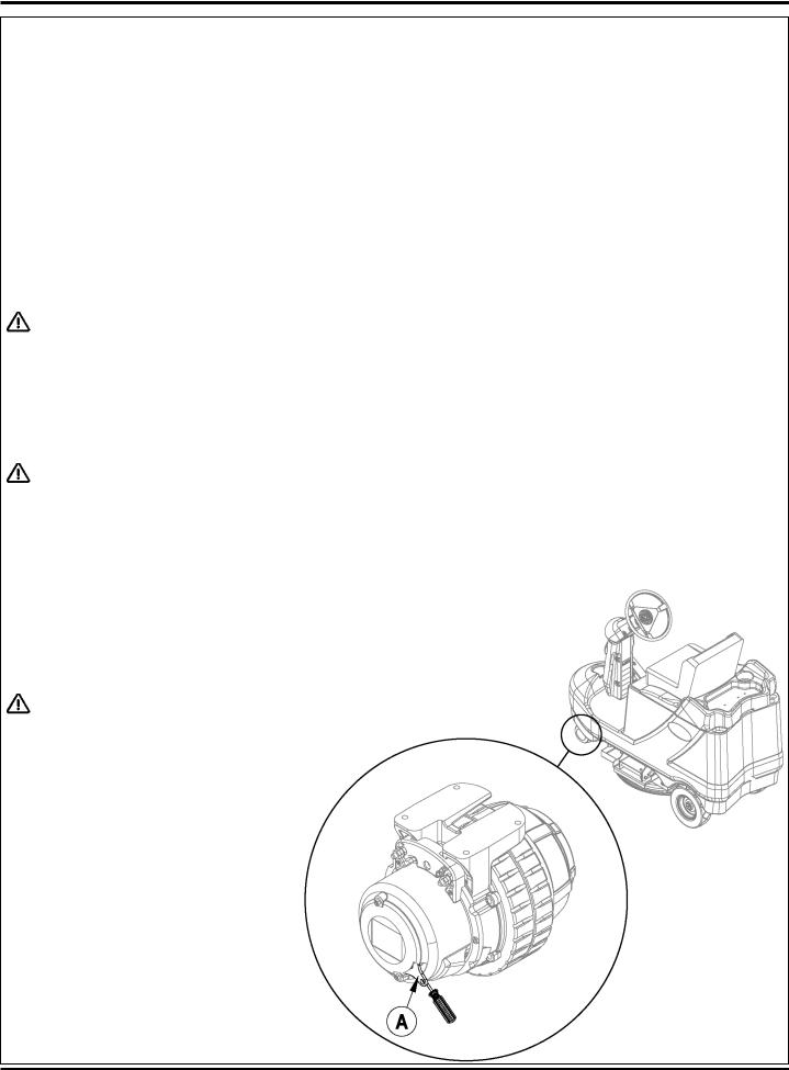
TOWING THE MACHINE
CAUTION!
The Drive / Steer Wheel Assembly (14) has a built in electromagnetic brake that is engaged whenever the Master Key Switch (AA) is OFF or the FWD / REV Drive Pedal (8) is in the neutral position. This brake can be manually over ridden if necessary by inserting a medium to large screwdriver behind the Yoke (A) as shown. This should only be done in the event you need to push or pull the unit.
8 - FORM NO. 56043107 - Advolution™ 2710 / UHR 70-1700

Advance Advolution 2710 & Nilfisk UHR 70-1700
Rider Burnisher
PM Checklist
Customer |
|
|
|
|
|
|
|
|
|
|
|
|
A |
Defect Codes |
|
|||||||
|
|
|
|
|
|
|
|
|
|
|
needs adjustment |
|
||||||||||
Address |
|
|
|
|
|
|
|
|
|
|
|
B |
binding |
|
|
|||||||
|
|
|
|
|
|
|
|
|
|
|
C |
dirty or contaminated |
||||||||||
City |
|
|
|
|
|
|
|
|
|
|
|
|
|
|
|
D damaged, bent or torn |
||||||
|
|
|
|
|
|
St |
|
|
Zip |
|
|
|
L |
leaks |
|
|
|
|||||
Model |
|
|
|
|
|
|
|
|
|
|
|
M |
missing |
|
|
|||||||
Serial |
|
Hours |
|
|
W |
worn out |
|
|
||||||||||||||
|
|
|
|
|
|
|
|
|
|
|
|
|
|
|
|
|
|
|
|
|
|
|
|
|
|
|
|
OPERATIONAL INSPECTION ITEMS |
|
|
Defect Codes |
Does |
|||||||||||||
Ref |
|
|
|
|
|
|
Not |
|||||||||||||||
|
|
|
|
|
|
|
|
|
|
|
|
|
|
|
OK |
|
|
(circle) |
Work |
|||
1 |
|
Steering |
|
|
|
|
|
|
|
|
|
|
|
|
|
A |
B |
|
|
|||
2 |
|
Drive System Pedal Operation (check for Fwd/Rev drive & any neutral creep) |
|
|
|
A |
B |
D |
|
|||||||||||||
3 |
|
Seat Safety Switch |
|
|
|
|
|
|
|
|
|
|
|
|
|
D |
W |
|
|
|||
4 |
|
Electrical Parking Brake (Brake releases when the key is turned on & the drive pedal is |
|
|
|
A |
B |
W |
|
|||||||||||||
|
|
engaged. Note machine should not move when machine is at rest.) |
|
|
|
|
|
|
|
|||||||||||||
5 |
|
Drive System Performance |
|
|
|
|
|
|
|
noisy |
sluggish |
|
||||||||||
6 |
|
Burnishing System Deck & Motor Operation (pad deck raise/lower & pad motor auto |
|
|
A |
B |
C |
D |
|
|||||||||||||
|
|
functions) |
|
|
|
|
|
|
|
|
|
|
|
|
|
|
|
|
|
|||
7 |
|
Burnishing System performance (even shine) |
|
|
|
|
|
|
|
|
A |
W |
|
|
||||||||
8 |
|
Emergency Battery Disconnect Control Knob |
|
|
|
|
|
|
|
|
B |
D |
|
|
||||||||
9 |
|
Tilt Steering Mechanism |
|
|
|
|
|
|
|
|
|
|
|
|
|
A |
B |
|
|
|||
10 |
|
Optional Accessories (Headlight, Safety Beacon, Active Dust Control System, Etc.) |
|
|
|
<-----> |
|
|
||||||||||||||
11 |
|
Battery Charger (auto turn ON & OFF) |
|
|
|
|
|
|
|
|
|
|
|
|
||||||||
12 |
|
Main Control Board Special Program Options (Reference SVR Manual 56043107) and |
|
|
|
|
A |
|
|
|||||||||||||
|
|
check all applicable program settings. Examples stored error fault codes, diagnostic |
|
|
|
|
|
|
|
|||||||||||||
|
|
SVR test mode, pad pressure settings etc. |
|
|
|
|
|
|
|
|
|
|
|
|
||||||||
|
|
|
|
|
|
|
|
|
|
|
|
|
|
|
|
|
|
|
|
|
|
|
|
|
|
|
|
VISUAL INSPECTION ITEMS |
|
|
|
|
|
|
|
Defect Codes |
Does |
||||||||
Ref |
|
|
|
|
|
|
|
|
|
|
|
Not |
||||||||||
|
|
|
|
|
|
|
|
|
|
|
|
|
|
Comments |
OK |
|
|
(circle) |
Work |
|||
13 |
|
Pad Motor Carbon Brushes (check for wear) |
|
|
|
|
|
|
|
|
C |
D |
W |
|
||||||||
14 |
|
Wheel Drive Motor Carbon Brushes (check for wear) |
|
|
|
|
|
|
|
|
C |
D |
W |
|
||||||||
15 |
|
Pad Deck Actuator Motor and Pad Drive Deck Levelness |
|
Perform a pad pattern |
|
|
|
A |
B |
D |
|
|||||||||||
|
|
|
|
|
|
|
|
|
|
|
|
|
|
|
test |
|
|
|
|
|
|
|
16 |
|
Pad Retainer, Pad Driver and Burnishing Pad (check for wear) |
|
|
|
|
|
D |
M |
|
|
|||||||||||
17 |
|
Dust Shroud Assembly Edging and Dust collection Bag |
|
|
|
|
|
|
|
|
D |
M |
W |
|
||||||||
18 |
|
Battery Condition (load test, clean & water) |
|
|
|
|
|
|
|
|
D |
L |
W |
|
||||||||
19 |
|
Check and Lubricate the Steering Wheel Universal Joint |
|
|
|
|
|
|
|
A |
B |
D |
W |
|
||||||||
20 |
|
Steer Chain Tension |
|
|
|
|
|
|
|
|
|
adjust |
|
|
A |
B |
C |
W |
|
|||
21 |
|
Drive and Steer wheels (thread wear) |
|
|
|
|
|
|
|
|
A |
D |
W |
|
||||||||
NOTE: For additional service information see service manual form number 56043107 and operators manual (English & Spanish) form number 56041634.
WORK COMPLETED BY: |
|
|
|
ACKNOWLEDGED BY: |
|
|
|
|
|
|
|
|
|
Service Technician Signature |
|
Date |
|
Customer Signature |
|
Date |
FORM NO. 56043107 - Advolution™ 2710 / UHR 70-1700 - 9
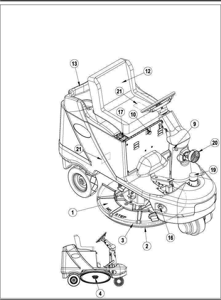
KNOW YOUR MACHINE
As you read this manual, you will occasionally run across a bold number or letter in parentheses - example: (2). These numbers refer to an item shown on these pages unless otherwise noted. Refer back to these pages whenever necessary to pinpoint the location of an item mentioned in the text.
1Pad Drive Deck
2Dust Control Shroud
3Burnishing Pad
4Pad Retainer
5Dust Collection Bag
6Machine Tie Down
7Battery Connector Assembly
8FWD/REV Drive Pedal
9Tilt Steering Wheel Adjuster
10Emergency Power Disconnect
11Steering Wheel
12Operator’s Seat W/Safety Switch
13Battery Compartment Cover
14Drive / Steer Wheel
15Circuit Breakers
40 Amp (Wheel Drive)
5 Amp (Control Circuit)
16Deck Latch
17I/O Panel (Indicator / Operation Panel)
18Spare Dust Bag Storage
19Beacon (Optional)
20Headlight (Optional)
21Active Dust Control (Optional)
22Onboard Charger (Optional)
23Serial Plate (qty of 2)
10 - FORM NO. 56043107 - Advolution™ 2710 / UHR 70-1700

KNOW YOUR MACHINE
AAMaster Key Switch
BBBattery Condition Indicator
CCHour Meter / Error Display
DDPad Drive Indicator Light
EEPad Drive Raise / Lower Switch
FFHorn Indicator Light
GGHorn Switch
FORM NO. 56043107 - Advolution™ 2710 / UHR 70-1700 - 11

FUNCTIONAL DESCRIPTION OF CONTROL BUTTONS:
Key Switch (AA) – Main Power Switch, when turned on controls battery input to machine’s main control board and wheel drive speed control.
Battery Condition Indicator (BB) – The Battery Condition Indicator will give an indication of the state of charge of the batteries. Three lights make up the Indicator Display (Red-Yellow-Green). See the electrical system in this manual for discharge percentage details of each indicator light.
Hour Meter/Error Display (CC) The 5-character display on the I/O Panel is primarily used as a display for the hour meter function. When the Key Switch (A) is activated pad pressure setting 1,2, or 3 will appear briefly in the right corner of the display. Followed by five 8’s to show functionality of the L.E.D. Display, then switching to hours on the unit. This display is also used to display the following information depending upon which mode the control is in:
•Error Codes*
•Pad Pressure Settings (1,2, and 3)
•Display of control system default parameters*
*Service Note: Have a qualified Service Technician reference the Service Manual for explanations about Error Codes and Control Fault + Parameter Changes. A description of Error Codes can be found in the electrical section of this manual
Pad Drive Indicator Light (DD) –
•Indicator will be blank (off) when deck is in the raised position.
•Indicator will be light Green when lowering the deck as the pad drive raise-lower switch is activated.
•Indicator will be dark Green when the Drive Pedal is engaged in Forward or Reverse activating the pad motor.
•Indicator will be Red when raising the deck as the pad drive/raise-lower switch is activated.
•At full raised position the Red light will go out.
Pad Drive Raise-Lower Switch (EE) – Pressing this switch will activate (turn on) the Lower/Raise burnishing deck lift actuator functions – see indicator lights description for further information.
Horn Indicator Light (FF) – Indicator Light will turn Green when Horn Switch is depressed. And also displays fault flash codes. NOTE: See electrical system Curtis Control diagnostics in this manual.
Horn Indicator Switch (GG) – Pressing this switch will activate (turn on) the horn, causing a horn like sound to emanate from the machine.
12 - FORM NO. 56043107 - Advolution™ 2710 / UHR 70-1700

BURNISHING SYSTEM FUNCTIONAL OVERVIEW
The machines: Advolution 2710 / UHR 70-1700 (Model numbers 56422000, 56422001 & 56411002) use the disk type burnishing system. The pad driver assembly is directly attached to a single 3.25hp – 36v DC permanent magnet motor.
The burnishing deck is raised and lowered by a horizontally mounted electric lift actuator motor. The operation of the machine’s burnishing functions are activated when the operator presses the main I/O Panel’s pad drive raise/lower switch (EE). NOTE: See the Electrical SystemAdvolution programming modes section of this manual for more detailed operation and instructions to change the burnishing pad pressure setting.
The machines main burnishing system input and output operating functions are regulated (managed) by the I/O Panel and the Control Box. For the Pad motor to function the operator must turn on (energize) the (K1) pad motor solenoid by pressing the Pad drive Raise/Lower switch (EE) on the I/O Panel and press the drive pedal moving it off it’s neutral position. These two operator functions deliver the required (A1) Speed control and Control Box circuit inputs and outputs for the burnishing operation. NOTE: See troubleshooting (page 22) section for more details.
|
|
|
|
|
|
|
RED |
2 |
F1 |
|
|
RED |
BT1 |
|
|
|
|
|
|
|
|
|
BLK |
|
||
|
|
|
|
|
|
|
|
|
1 |
|
|
- - - |
|
|
|
|
|
|
|
|
|
|
|
|||
|
|
|
|
|
|
|
|
FUSE, 150 A. |
|
|
|
|
|
|
|
|
|
|
|
|
|
|||||
|
|
|
|
|
|
|
|
|
|
BATTERY, 36 VDC |
|
|
|
|
|
|
|
|
||||||||
|
|
|
|
|
|
|
|
|
|
|
|
|
A1 |
|
CURTIS 1228 SPEED CONTROLLER |
|
|
|
|
|
|
|
||||
|
|
|
|
|
|
|
|
|
|
|
|
|
A1 |
|
|
|
|
|
|
|
|
|
|
|
|
|
|
|
|
|
|
|
|
|
|
|
|
|
|
|
|
|
GRN |
|
|
|
VIO/BRN |
|
3 |
|
|
||
|
|
|
|
|
|
|
|
|
|
|
|
|
|
|
|
|
|
|
|
|
|
|
|
|||
|
|
|
|
|
|
|
|
|
|
|
|
|
|
|
|
|
|
|
GRA |
|
|
R1 |
|
|||
|
|
|
|
|
|
|
|
|
|
|
|
|
|
|
|
|
|
|
|
|
2 |
|
||||
|
|
|
|
|
|
|
|
|
|
|
|
|
|
|
|
RED/WHT |
GRN/BLK |
|
POT. 5K OHM |
|
||||||
|
|
|
|
|
|
|
|
|
|
|
|
|
|
|
|
|
|
|
|
|||||||
|
|
|
|
|
|
|
|
|
|
|
|
|
|
|
|
|
|
J7 |
ORN/BLK |
|
|
|
1 |
|
|
|
|
|
|
|
|
|
|
|
|
|
|
|
|
|
|
|
|
|
1 2 3 4 5 6 7 8 9 |
|
|
|
|
|
|
||
|
|
|
|
|
|
|
|
|
|
|
|
|
|
|
|
|
|
|
|
|
|
|
|
|
|
|
|
|
|
|
|
|
|
|
|
|
|
|
|
|
B+ B- |
(b) |
(a) |
(b) |
(a) |
10 11 12 13 14 15 16 17 18 |
VIO/BRN |
|
|
|
|
|
|
|
|
|
CB2 |
|
|
|
|
|
|
|
|
|
|
M2 |
M2 |
M1 |
M1 |
|
|
|
BRN/BLK |
|
|
|
|
|
|
RED |
|
|
|
|
|
|
|
|
GRN/WHT |
|
|
|
|
|
|
|
|
|
|
||||||
|
1 |
|
2 |
|
|
|
|
|
|
|
|
|
|
|
|
|
|
|
|
|
|
|
||||
|
|
|
|
|
|
|
|
|
|
|
|
|
|
|
|
|
|
|
|
|
|
|||||
|
|
|
|
|
|
|
|
|
|
|
|
|
|
|
|
|
YEL/WHT |
|
|
|
|
|
|
|
||
|
CIRCUIT BREAKER, 40 AMP |
|
|
|
|
|
|
|
|
|
|
RED/GRN |
|
|
YEL/BLK |
|
|
|
|
|
|
|
||||
|
|
|
|
|
|
|
|
|
|
|
|
|
|
|
|
|
|
|
|
|
||||||
|
|
|
|
|
|
|
|
|
|
|
|
|
|
BLK |
|
|
|
|
|
|
|
|
|
|
||
|
|
|
|
|
|
|
|
|
|
|
|
|
|
|
|
M1 |
|
|
|
|
|
|
|
|
|
|
|
|
|
|
ON-BOARD |
|
|
|
|
PLUG AC MALE |
|
|
- |
M |
+ |
ORN |
|
|
|
|
|
|
|
||||
|
|
|
|
|
|
|
|
|
|
|
|
|
|
|
|
|
|
|
|
|
|
|
|
|
||
|
|
|
|
BATTERY CHARGER |
|
|
|
|
|
|
|
|
|
|
|
|
|
|
|
|
|
|
|
|
||
|
|
RED |
|
(OPTIONAL) |
|
|
|
BLK |
|
|
|
|
|
|
MOTOR, TRACTION |
|
|
|
|
|
|
|
||||
|
|
|
|
|
|
|
|
|
|
|
|
|
|
|
|
|
|
|
|
|
|
|
|
|
||
|
|
|
|
|
|
|
S10 |
|
|
|
S2 |
|
RED/WHT |
2 |
Y1 |
1 |
|
|
|
|
|
|
|
|
|
|
|
|
|
|
|
EMERGENCY STOP |
|
SWITCH, SEAT |
|
|
|
|
|
|
|
|
|
|
|
|
|||||||
|
|
|
|
|
|
|
|
YEL |
1 |
2 |
GRN |
|
BRAKE |
|
|
|
|
|
|
|
|
|
|
|
||
|
|
|
|
|
|
|
|
|
|
|
|
|
|
|
|
|
|
|
|
|
|
|
||||
|
|
|
|
|
|
|
WHT/ORN |
|
|
|
|
|
|
|
|
|
|
|
|
|
|
|
|
|
|
|
|
|
CB1 |
|
|
|
|
|
|
|
|
|
|
RED/WHT |
J3-10 (F/R) |
|
|
|
|
|
|
|
|
|
|
|
|
RED |
|
|
|
VIO |
VIO |
|
|
WHT/ORN |
|
|
GRN |
|
|
|
|
YEL/WHT |
|
|
|
|
|
|
||||
1 |
|
2 |
1 |
2 |
|
|
J3-9 (SEAT SW) |
|
|
(REV) J3-6 |
|
|
|
|
|
|
||||||||||
|
|
|
|
|
SWITCH, KEY |
|
|
|
|
|
|
|
|
|
|
ORN/BLK |
|
|
|
|
|
|
||||
CIRCUIT BREAKER, 5 AMP |
|
|
|
|
|
|
|
|
|
|
(STATUS) J3-4 |
|
|
|
|
|
|
|||||||||
|
|
|
|
|
|
|
|
|
|
|
|
|
|
|
|
|
||||||||||
|
|
S1 |
|
|
|
|
|
WHT/ORN |
|
|
|
|
|
|
GRN/BLK |
|
|
|
|
|
|
|||||
|
|
|
|
|
|
|
|
|
|
|
|
J3-2 (KEY SW) |
|
|
(MODE) J2-2 |
|
|
|
|
|
|
|||||
|
|
|
|
|
|
|
|
|
|
|
|
|
|
|
|
|
|
|
|
|
|
|
||||
|
|
|
|
|
|
|
|
|
|
|
|
|
VIO |
|
|
|
|
|
(SDA) J1-1 |
PINK |
J4-1 (SDA) |
|
|
|
|
|
|
|
|
|
|
|
|
|
|
|
|
|
|
J3-1 (B+) |
|
|
|
ORN/WHT |
|
|
|
|
|||||
|
|
|
|
|
|
|
|
|
|
|
|
|
|
|
|
|
(SCL) J1-2 |
J4-2 (SCL) |
|
|
|
|
||||
|
|
|
|
|
|
|
|
S5 |
|
|
|
|
|
|
|
|
|
|
BLU/BLK |
|
|
|
|
|||
|
|
|
|
|
|
|
|
|
|
LP5 |
|
|
|
|
|
|
(+5 V) J1-3 |
J4-3 (+5 V) |
|
I/O PANEL |
|
|||||
|
|
|
|
|
|
|
|
|
|
|
|
|
|
|
|
|
|
|
||||||||
|
|
|
|
|
|
|
VIO |
|
|
|
WHT/BRN |
|
|
|
|
|
BRN |
|
|
|||||||
|
|
|
|
|
|
|
1 |
|
2 |
1 |
2 |
J2-4 (ACC (-)) |
|
|
(HORN SW) J1-4 |
|
|
|
|
|||||||
|
|
|
|
|
|
|
|
|
|
|
|
BLK/GRA |
J4-4 (HORN SW) |
|
|
|||||||||||
|
|
|
|
|
|
|
|
SW SPST |
|
LAMP, HEAD |
|
|
|
|
|
|
|
|
||||||||
|
|
|
|
|
|
|
|
|
|
|
|
|
|
|
(B-) J1-5 |
J4-5 (B-) |
|
|
|
|
||||||
|
|
|
|
|
|
|
|
|
|
|
|
|
|
|
|
|
|
|
|
|||||||
|
|
|
|
|
|
|
|
|
|
|
|
(OPTIONAL) |
|
|
|
|
|
|
BLU |
|
|
|
|
|||
|
|
|
|
|
|
|
|
|
|
|
|
|
|
|
|
|
|
(PAD SW) J1-6 |
J4-6 (PAD SW) |
|
|
|||||
|
|
|
|
|
|
|
|
|
|
|
LP6 |
|
|
|
|
|
|
|
|
|
||||||
|
|
|
|
|
|
|
|
|
|
|
|
|
|
|
|
|
|
|
|
|
|
|
|
|
||
|
|
|
|
|
|
|
|
|
VIO |
1 |
2 |
WHT/BRN |
|
CONTROL BOX |
|
|
H1 |
|
|
|
||||||
|
|
|
|
|
|
|
|
|
|
|
|
|
|
|
|
|
|
|
|
|
|
|
|
|
||
|
|
|
|
|
|
|
|
|
|
LAMP, FLASHING |
|
|
|
|
|
|
(HORN +) J2-7 |
GRA/WHT |
|
+ |
|
- |
|
|
||
|
|
|
|
|
|
|
|
|
|
(OPTIONAL) |
|
|
|
|
|
|
BRN/WHT |
|
|
|
|
|||||
|
|
|
|
|
|
|
|
|
|
|
|
|
|
|
|
|
|
|
|
|
|
|
||||
|
|
|
|
|
|
|
|
|
|
|
|
|
|
|
|
|
|
|
(HORN -) J2-1 |
|
|
|
|
|
|
|
|
|
|
|
|
|
|
|
|
|
|
|
|
|
|
|
|
|
|
|
|
|
|
|
|
|
|
|
|
|
|
|
|
|
|
1 |
S3 |
|
|
GRA/BLK |
J3-7 (INTERLOCK B-) |
|
|
|
HORN/BACK-UP ALARM |
|
||||||||
|
|
|
|
|
|
|
|
|
2 |
|
|
|
|
|
|
|
|
|
|
|||||||
|
|
|
|
|
|
|
|
|
|
|
|
|
VIO/BLK |
|
|
|
|
|
|
|
|
|
|
M3 |
|
|
|
|
|
|
|
|
|
|
|
|
|
|
|
J3-5 (INTERLOCK) |
|
(ACT 1) J2-12 |
WHT/RED |
|
- |
|
M |
+ |
|
||||
|
|
|
|
|
|
|
|
SWITCH, DECK INTERLOCK |
|
|
|
|
|
|||||||||||||
|
|
|
|
|
|
|
|
|
|
|
|
|
|
|
|
|
|
|||||||||
|
|
|
|
|
|
|
|
|
|
|
|
|
|
|
|
|
|
|
(ACT 2) J2-6 |
ORN/BLU |
|
|
|
|
|
|
|
|
|
|
|
|
|
|
|
|
K1 |
|
|
|
|
|
|
|
|
|
|
|
|
|
|
|
|
|
|
|
|
|
|
|
|
|
|
|
|
|
|
|
|
|
|
|
BLK |
|
ACTUATOR |
|
||||
|
|
|
|
|
|
|
|
|
|
K1 |
|
|
BLK/WHT |
|
|
|
|
|
(B-) J2-9 |
|
|
|
|
|
|
|
|
|
|
|
|
|
|
|
|
|
|
|
|
J2-5 (PAD CONT -) |
|
BLK |
|
|
|
|
|
|
|||||
|
|
|
|
|
|
|
|
|
|
|
|
|
|
|
(B-) J2-10 |
|
|
|
|
|
|
|||||
|
|
|
|
|
|
|
|
|
|
|
|
|
|
|
|
|
|
|
BLK |
|
|
|
|
|
|
|
|
|
|
|
|
|
|
|
|
|
COIL, RELAY |
BLU/WHT |
J2-11 (PAD CONT +) |
(B-) J3-8 |
|
|
|
|
|
|
|||||||
|
|
|
|
|
|
|
|
|
|
BLK/YEL |
|
|
|
|
|
|
||||||||||
|
|
|
|
|
|
|
|
|
|
|
|
|
|
(SENSE) J3-3 |
|
|
|
|
|
|
||||||
|
|
|
|
|
|
|
|
|
|
|
|
|
|
|
|
|
|
|
|
|
|
|
|
|
||
|
|
|
|
|
|
|
|
|
|
|
|
|
|
|
|
|
|
|
|
|
|
|
|
|
|
|
|
|
|
|
|
|
|
|
RED |
K1K1 |
|
|
|
|
RED |
|
|
|
|
|
|
|
M2 |
|
BLK |
||
|
|
|
|
|
|
|
|
1 |
|
2 |
|
|
|
|
|
|
|
|
|
+ |
M |
- |
||||
|
|
|
|
|
|
|
|
|
|
|
|
|
|
|
|
|
|
|
|
|
|
|||||
|
|
|
|
|
|
|
|
|
|
|
|
|
|
|
|
|
|
|
|
|
|
MOTOR, PAD |
|
|||
|
|
|
|
|
|
|
|
|
|
|
|
|
|
|
|
|
|
|
|
|
S9 |
|
|
|
|
|
|
|
|
|
|
|
|
|
|
|
|
|
|
|
|
WHT |
|
|
|
1 |
|
2 |
1 |
|
2 |
BLK |
|
|
|
|
|
|
|
|
|
|
|
|
|
|
|
|
|
|
|
|
|
|
|
|
|
|
||
SW SPST
M4
M
MOTOR, DUST CONTROL VAC
(OPTIONAL)
56015612 REV. F
FORM NO. 56043107 - Advolution™ 2710 / UHR 70-1700 - 13

BURNISHING SYSTEM
PAD LIFT ACTUATOR REMOVAL AND INSTALLATION
WARNING!
Disconnect the battery pack by separating the battery connectors (7) whenever servicing the machine.
1Disconnect the battery pack by separating the battery connectors (7) located underneath the drivers seat.
2Disconnect the actuator wiring harness at the actuator lift motor.
3See Figure 1. Remove the (2) Hex Screws (A) that fasten the actuator Mount Bracket (B).
4Remove the Retainer Ring (C). NOTE: Remove the retainer closest to the front of the machine. Then slide the mount pin (D) to the rear to allow removal of the Actuator (E) from the machine.
5To re-install follow the above instructions in reverse order. NOTE: See the Actuator Lift Nut Adjustment section in this manual for correct lift nut adjustment setting as new actuators do not come pre-set.
PAD DRIVE DECK REMOVAL
WARNING!
Disconnect the battery pack by separating the battery connectors (7) whenever servicing the machine.
1Disconnect the battery pack by separating the battery connectors (7) located underneath the drivers seat.
2See Figure 1. Remove the (2) Deck Springs (F) from the right side of the lower deck housing. NOTE: Use a pliers to assist in disconnecting the springs. Having the deck in the up position will also make it easier (less tension).
3Attach the Advance actuator adapter cord (P.N. 56407502) to the deck Actuator (E) and lower deck. This step is done to gain service access to the motor wiring and lift linkage mount hardware.
4Disconnect the deck’s Safety Switch (G) at its harness connector.
5Remove the (2) pad motor wires. NOTE: Mark the Red (-) & Black (+)wire locations.
Service Tip: Measure the height of the Front to Back Deck Level Adjustment Screw (H) before disassembling (should be approximately 1- 1/8”(28.44mm)).
6Loosen Lock Nut (I) and thread it down. At the same time remove the Adjustment Screw (H) from the Pivot Shaft (J).
7Tap the Shaft (J) toward the rear tire to complete its removal.
Service Tip: The shaft is spaced with (2) Nylon Washers (K), note their location for reassembly. 8 Slide the deck assembly out from under the machine.
PAD DRIVE MOTOR CARBON BRUSH INSPECTION
1Follow instructions for Pad Drive Deck Removal.
2See Figure 1. Remove the Motor Air Filter (L). NOTE: Inspect the condition of the filter band and clean or replace as needed.
3Remove the motor Brush Cover (M) secured by (4) Phillips head screws (N).
4Inspect carbon brushes and springs. NOTE: New carbon brushes measure 1-3/32 (28mm). If the brushes are less than 3/8” (10mm) long they should be replaced.
5Important Maintenance Tip: Always blow out motor before reassembling
6Motor wiring tip: The Red cable goes to NEGATIVE Stand off on the motor and the Black cable goes to the POSITIVE Stand off on the motor.
14 - FORM NO. 56043107 - Advolution™ 2710 / UHR 70-1700
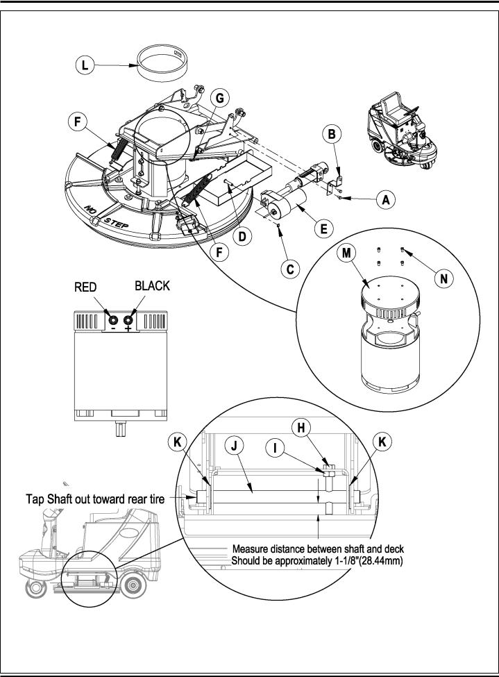
FIGURE 1
FORM NO. 56043107 - Advolution™ 2710 / UHR 70-1700 - 15
BURNISHING SYSTEM
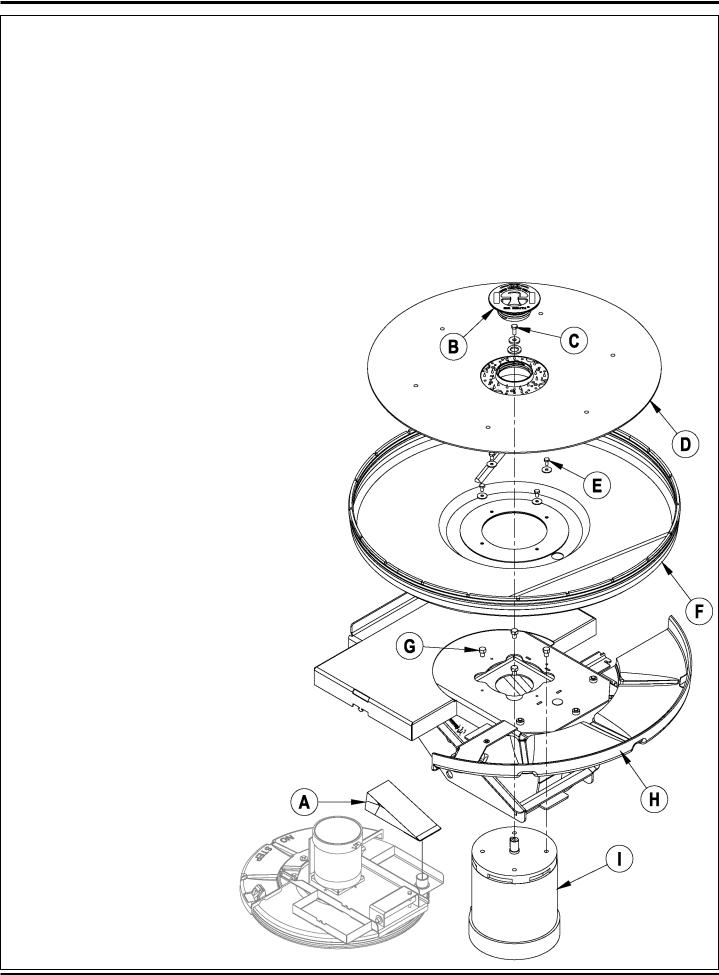
PAD DRIVE MOTOR REMOVAL
1Follow instructions for Pad Drive Deck Removal.
2See Figure 2. Remove the Dust Bag (A).
3Tip the deck assembly over and remove the Pad Retainer (B), pad (if installed) and the Motor Shaft Screw (C) that fastens the Pad Driver Assembly (D) to the motor shaft.
4Remove the Pad Driver Assembly (D) from the motor shaft. NOTE: Do not lose the motor shaft key.
5Remove the (4) Screws (E) and the Dust Shroud (F).
6Remove the (4) Screws (G) that fasten the motor to the deck plate. Lift the remaining Deck Assembly (H) off the Motor (I) to complete its removal. NOTE: Mark motor terminal location for reassembly.
7Follow the above steps in reverse order to reinstall the Pad Drive Motor.
DUST SHROUD REMOVAL
1See Figure 2. Remove the Dust Bag (A).
2Remove the Pad Retainer (B), pad (if installed) and the Motor Shaft Screw (C) that fastens the Pad Driver Assembly (D) to the motor shaft.
3Remove the Pad Driver Assembly (D) from the motor shaft. NOTE: Do not lose the motor shaft key.
4Remove the (4) Screws (E) and the Dust Shroud (F).
FIGURE 2
16 - FORM NO. 56043107 - Advolution™ 2710 / UHR 70-1700
BURNISHING SYSTEM
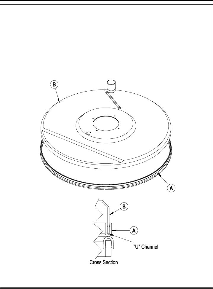
DUST SHROUD EDGING REPLACEMENT
1See Figure 3. Remove existing Edging (A) by pulling it away from the Shroud (B).
2To install start at the rear of the Shroud (B) with one end of the new Edging (A) so that the seam is hidden. Push “U” channel onto Shroud
(B), work edging assembly around Shroud (B).
3Check that Edging (A) “U” channel is firmly in place all around Shroud (B). NOTE: Pinch the “U” channel every 3 to 4 inches with a visegrips to ensure it is securely fastened to the shroud.
FIGURE 3
FORM NO. 56043107 - Advolution™ 2710 / UHR 70-1700 - 17
BURNISHING SYSTEM
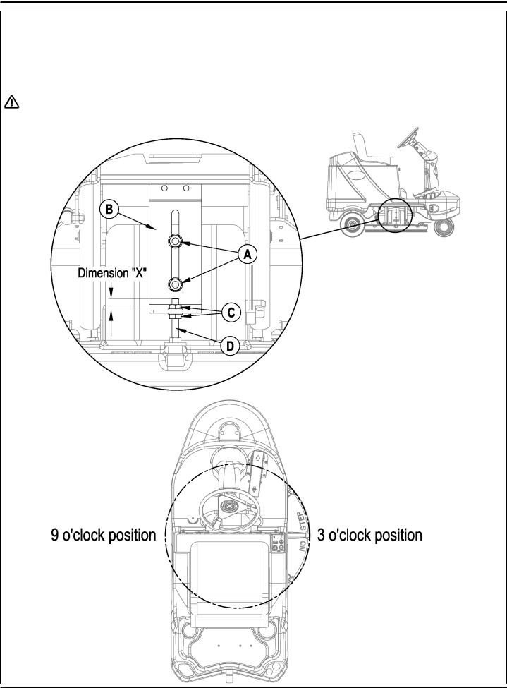
PAD DRIVE DECK LEVEL ADJUSTMENT
NOTE: Install a new pad before performing this adjustment.
1Put the pad drive deck in the down position.
2Briefly run the pad drive motor to get a pattern on the floor.
CAUTION!
Do not run pad motor for an extended period without moving machine.
FIGURE 4
Left to Right Pad Contact Adjustment – See Figure 4.
1Loosen the (2) Nuts (A) on the Adjustable Bracket (B).
2Turn the (2) Lock Nuts (C) on the Carriage Screw (D) either down to increase or up to decrease Dimension “X”. Decreasing Dimension “X” will increase the pad pressure at the 3 O’clock position.
Increasing Dimension “X” will increase the pad pressure at the 9 O’clock position.
NOTE: As a general rule the measurement at the 3 o’clock and the 9 o’clock position should be the same when measured from the floor to the edge of the dust shroud.
18 - FORM NO. 56043107 - Advolution™ 2710 / UHR 70-1700 |
revised 6/08 |
 Loading...